DGN9033 - Stapler DEWALT - Free user manual and instructions
Find the device manual for free DGN9033 DEWALT in PDF.

| Product Type | Gas Nailer (Stapler) |
| Brand | DeWalt |
| Model | DGN9033 |
| Length | 374 mm |
| Height | 378 mm |
| Width | 108 mm |
| Weight | 3.42 kg |
| Power Supply | Rechargeable Ni-MH battery 6V 1.6 Ah (DG-B03-XJ) + charger DG-C02-XJ (input 100-240 V AC) |
| Fuel | Propane/butane gas cartridge 80 ml (DGFC80MLHP) |
| Staple/Nail Dimensions | Diameter 2.8-3.3 mm, length 50-90 mm |
| Magazine Capacity | 60 nails |
| Firing Mode | Sequential firing (safety trigger) |
| Depth Adjustment | Yes, by moving the contact arm |
| Sound Level (LPA) | 94.5 dB(A) |
| Sound Level (LWA) | 96.4 dB(A) |
| Vibration | 3.4 m/s² (uncertainty 1.7 m/s²) |
| Operating Temperature | -7°C to 49°C |
| Storage Temperature | Max 50°C |
| Battery Indicator | Flashing green (sufficiently charged) or red (low) |
| Power Saving Mode | Automatic after 1 hour of inactivity |
| Maintenance | Filter and combustion chamber cleaning, regular lubrication |
| Spare Parts | List provided, repair by DeWALT authorized service center |
| Warranty | 12 months (parts and labor) |
| Safety | Safety glasses and ear protection mandatory; do not use in flammable environments |
Frequently Asked Questions - DGN9033 DEWALT
User questions about DGN9033 DEWALT
0 question about this device. Answer the ones you know or ask your own.
Ask a new question about this device
Download the instructions for your Stapler in PDF format for free! Find your manual DGN9033 - DEWALT and take your electronic device back in hand. On this page are published all the documents necessary for the use of your device. DGN9033 by DEWALT.
USER MANUAL DGN9033 DEWALT
GB EC DECLARATION OF CONFORMITY
The gas nailer DGN9033 meets the applicable requirements of the following standards: EN 55014-1:2005+A1:2009 + A2:2011, EN 55014-2:1997+A1:2008, EN 61000-3-2:2006, EN 61000-3-3:2008, EN 60335-1:2012, EN 60335-2-29:2004 + A2:2010, EN 792-13:2000+A1:2008, EN 61558-1:2005 + A1:2009, EN 61558-2-16:2009 + A1:2013, EN 50581:2012. We hereby declare that the product meets the applicable requirements of the following Directives: 2006/42/EC, 2004/108/EC (until 19.04.16), 2014/30/EU (from 20.04.16) 2006/95/EC (until 19.04.16), 2014/35/EU (from 20.04.16) and 2011/65/EC. The technical documentation is available from the manufacturer at the address below.
FR DÉCLARATION DE CONFORMITÉ CE
English TOOL TECHNICAL DATA (original instructions) 6
natural_image
Close-up of a black and white electric drill bit (no visible text or symbols)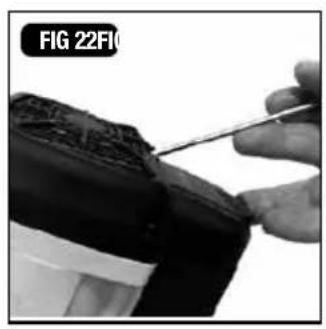
natural_image
Close-up of a hand using a screwdriver to apply material on a textured surface (no visible text or symbols)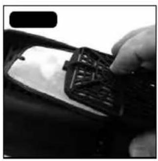
natural_image
Close-up of a hand holding a dark textured object, possibly a mechanical part or device (no visible text or symbols)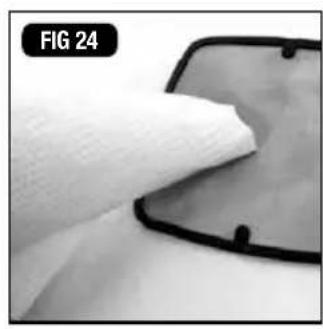
natural_image
Close-up of a white fabric being smoothed with a black outline, labeled 'FIG 24' in the corner (no other text or symbols)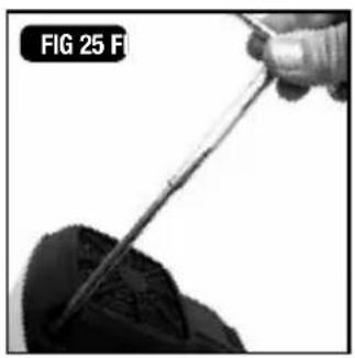
natural_image
Close-up of a hand holding a pen tip over a dark object, labeled 'FIG 25 FI' (no other text or symbols visible)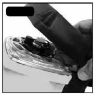
natural_image
Close-up of a hand holding a small object with dark debris, possibly a mechanical component or tool (no visible text or symbols)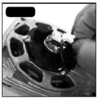
natural_image
Close-up of a hand holding a small mechanical component with a metallic tool inserted (no visible text or symbols)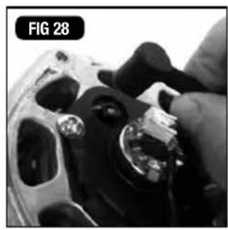
natural_image
Close-up of a hand adjusting a mechanical component, possibly a tool or fixture, with no visible text or symbols.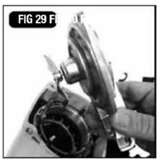
natural_image
Close-up of a hand adjusting a mechanical component, no visible text or symbols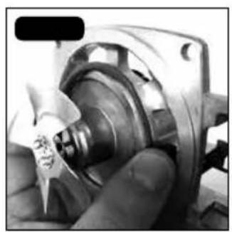
natural_image
Close-up of a mechanical component being handled, showing internal gears and shaft (no visible text or symbols)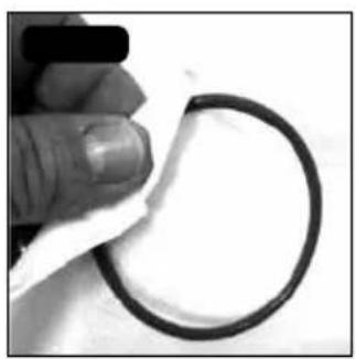
natural_image
Close-up of a hand holding a white adhesive tape next to a black circular ring (no text or symbols visible)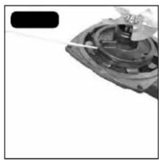
natural_image
Close-up of a mechanical component with a tool inserted, no visible text or symbols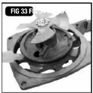
natural_image
Close-up of a mechanical component with a central fan-like structure and mounting base (no visible text or symbols)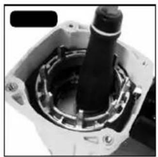
natural_image
Close-up of a mechanical component with a cylindrical shaft and housing (no visible text or symbols)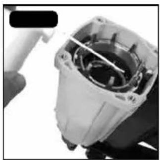
natural_image
Close-up of a mechanical component with internal structure, possibly a motor or housing (no visible text or symbols)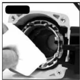
natural_image
Close-up of a hand holding a white plastic object into a mechanical component (no visible text or symbols)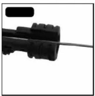
natural_image
Close-up of a black plastic electrical plug with a wire, no visible text or symbols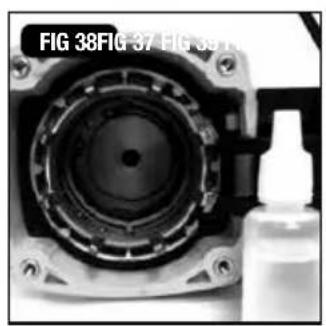
natural_image
Close-up of a camera lens assembly with a bottle beside it (no visible text or symbols)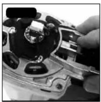
natural_image
Close-up of a hand adjusting a mechanical component with a metallic handle (no visible text or symbols)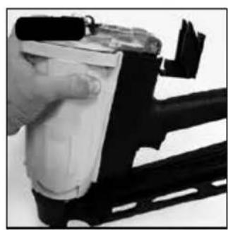
natural_image
Close-up of a hand operating a white pad or connector on a black metal frame (no visible text or symbols)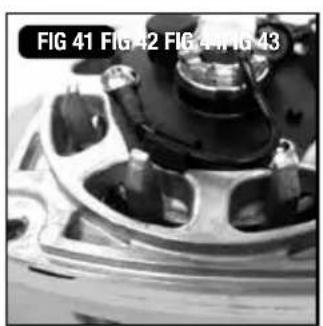
natural_image
Close-up of a mechanical component with no visible text or symbols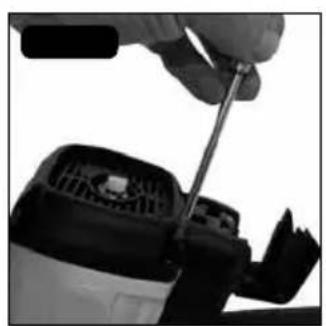
natural_image
Close-up of a hand using a screwdriver to adjust or install a mechanical component (no visible text or symbols)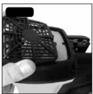
natural_image
Close-up of a hand holding a black plastic fan with a grid pattern (no visible text or symbols)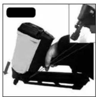
natural_image
Close-up of a mechanical device with a cylindrical component and a hand operating a tool (no visible text or symbols)GAS POWERED FRAMING NAILER - DGN9033-XJ
Congratulations!
You have chosen a DEWALT tool. Years of experience, thorough product development and innovation make DEWALT one of the most reliable partners for professional power tool users.
Safety and operation manual

THIS POWER TOOL IS POWERED BY AN INTERNAL COMBUSTION DEVICE AND SHOULD ONLY BE USED WITH THE DISPENSERS OF COMBUSTIBLE GAS WHICH ARE LISTED IN THESE HANDLING INSTRUCTIONS.


HEARING AND EYE PROTECTION MUST BE WORN
BEFORE OPERATING THIS TOOL, ALL OPERATORS SHOULD STUDY THIS MANUAL AND THE TOOL TECHNICAL DATA TO UNDERSTAND AND FOLLOW THE SAFETY WARNINGS AND INSTRUCTIONS. KEEP THESE INSTRUCTIONS WITH THE TOOL FOR FUTURE REFERENCE.
IF YOU HAVE ANY QUESTIONS, CONTACT YOUR DEWALT REPRESENTATIVE OR DISTRIBUTOR.
DeWALT tools have been designed to provide excellent customer satisfaction and are designed to achieve maximum performance when used with precision DeWALT fasteners, engineered to the same exacting standards. They will deliver efficient, dependable service when used correctly and with care. As with any fine power tool, the manufacturer's instructions must be followed for best results.
Note: Additional safety measures may be required because of your particular application of the tool. Contact your DeWALT representative or distributor with any questions concerning the tool and its use.
Note: DeWALT cannot assume responsibility for product performance if any of our tools are used with fasteners or accessories not meeting the specific requirements established for genuine DeWALT nails, staples, batteries, fuel cells, chargers and accessories.
LIMITED WARRANTY
DeWALT is confident of the quality of its products and offers a guarantee for professional users of the product. This guarantee statement is in addition to and in no way prejudices your contractual rights as a professional user or your statutory rights as a private non-professional user. The guarantee is valid within the territories of the Member States of the European Union and the European Free Trade Area.
If your DEWALT product becomes defective due to faulty materials or workmanship within 12 months from the date of purchase, DEWALT guarantees to replace all defective parts free of charge or – at our discretion – replace the unit free of charge provided that:
- The product has not been misused • The product has been subject to fair wear and tear; Driver blades, bumpers, and O rings are considered normally wearing parts and are excluded • Repairs have not been attempted by unauthorised persons • Proof of purchase is produced
- The product is returned complete with all original components
- The product is returned at your expense together with proof of purchase to our regional repair centre, or an authorised warranty centre.
If you wish to make a claim, contact your seller or check the location of your nearest authorised DeWALT repair agent in the DeWALT catalogue or contact your DeWALT office at the address indicated in this manual.
Accessories
These tools are supplied with the following accessories:
1) Battery charger x 1
2) Case x 1
3) Hexagonal bar wrench for M5 screws x 1
4) Battery x 2
Optional accessories are also available and sold separately:
1) Fuel cells Code ref: DGFC80MLHP
General safety instructions
Only those fasteners, batteries, fuel cells and chargers that are specified in these operating instructions should be used with the tool. The tool and the specified fasteners are to be considered as one single system for safety purposes.
Repairs shall only be carried out by the authorised agents of DeWALT or by other experts, giving due regard to the safety, operating and maintenance instructions in this manual and tool technical data.
Note: Experts are those who, as a result of professional training or experience, have acquired sufficient expertise in the field of fastener driving tools as to be able to assess the safe condition of fastener driving tools.
IN ADDITION TO THE OTHER WARNINGS IN THIS MANUAL OBSERVE THE FOLLOWING FOR SAFE OPERATION:
Do not dispose of electric tools together with household waste material!

In observance of European Directives 2002/96/EC & 2006//66/EC on waste electrical and electronic equipment/batteries and their national implementations, electric tools/batteries that have reached the end of their life must be collected separately and returned to an approved recycling facility.
- Respect youDEWALT tool as a tool. It is not a toy. No Horseplay.
- This tool is intended to be used for fastening wood to wood in pallet/crate and construction applications. DO NOT USE for fastening harder materials which could cause buckling of the fasteners and damage to the tool. If you are unsure of the suitability of this tool for certain applications, please contact your local sales office.
● Do not drive a nail on another nail.
● Do not drive a nail on metal parts.
● Never use the tool in a manner that could cause a fastener to be directed towards the user or others in the work area.
● Do not use the tool as a hammer.
● Always carry the tool by the handle. Never carry the tool with the trigger pulled.
- Do not alter or modify this tool from the original design or function without the written approval of DEWALT.
● Always be aware that misuse and improper handling of this tool can cause injury to yourself and others.
● Never clamp or tape the trigger or safety trip in an actuated position.
● Never leave a tool unattended with a fuel cell or battery in place.
- Do not operate this tool if it does not contain a legible WARNING LABEL.
- Do not continue to use a tool that does not function properly. Notify your nearest DEWALT representative if your tool experiences functional problems.
● During operation, hold the tool in such a way that no injuries can be caused to the head or to the body should the tool recoil increase due to variations in the gas supply or hard areas within the work piece. - Do not work close to corners or at the edge of the work piece. The fastener could slip out of the work piece, possibly causing injury.
- When transporting the tool, remove the fuel cell and battery.
- Check that the safety trip (if present) and the trigger both function correctly before use.
- Do not dismantle or block any part of the tool, particularly the safety trip.
- Never perform “emergency repairs” without the proper equipment.
● Avoid weakening the tool by punching or engraving. - This power tool is powered by an internal combustion device. This power tool should only be used with dispensers of combustible gas which are listed in these handling instructions.
● Never let the tool be used by children or people who do not know enough to be able to handle it correctly. - Keep the right parts in the right places. Do not remove any of the covers or screws. Keep them in place as they have their functions. Moreover, never make modifications to the tool or use it after making any modifications.
- Check the tool before use. Before using the tool, always check that no parts are broken, that all screws are completely tight, and that no parts are missing or rusty.
- Excessive work could cause accidents. Do not make tools and accessories work beyond their abilities. Excessive work not only damages the power tool but also is dangerous in itself.
- Stop operation immediately if you notice abnormalities or if the power tool does not work properly; have the power tool inspected and serviced.
● Take good care of the tool to ensure its long life. Always take good care of the power tool and keep it clean.
● Inspection at regular intervals is essential for safety. Inspect the power tool at regular intervals so that the tool can be operated safety and efficiently at all times.
- Avoid dangerous environments. Do not expose the power tools or charger to rain and do not use the power tool and charger in damp or wet conditions. Keep the work area well lit. Never use power tools and charger near flammable or explosive materials. Do not use the tool and charger in the presence of flammable liquids or gases.
- Store the tool and charger in an idle state. When not in use, the tool and charger should be stored in a dry, high or locked-up place – out of the reach of children and the infirm. Store the tool and charger in a place where the temperature is less than 40°C.

Do not abuse the cord. Never carry the charger by the cord or yank it to disconnect it from the mains. Keep the cord away from heat, oil and sharp edges.
- When the charger is not in use, or when being maintained and inspected, disconnect the power cord of the charger from the mains.
● To avoid danger, always use only the specified charger. - To avoid personal injury, only use the accessories or attachments recommended in these handling instructions or in the DEWALT catalogue.
- Check and confirm that the supply cord and housing are not damaged before using the charger. If the supply cord of this charger or housing is damaged, the charger must be returned to the DEWALT authorised service center for the cord or housing to be replaced. Only the authorised service center should do these repairs. DEWALT will not be responsible for any damages or injuries caused by unauthorised persons attempting to repair the tool, or mishandling of the tool.
● To ensure the designed operational integrity of the power tool and charger, do not remove installed covers or screws.
● Always use the charger at the voltage specified on the nameplate.
● Always charge the battery before use.
● Never use a battery other than that specified. Do not connect a non-tool specific dry cell, or a rechargeable battery other than that specified or a car battery to the power tool.
● Do not use a transformer containing a booster. - Do not charge the battery from an engine, electric generator or DC power supply.
ADDITIONAL SAFETY EQUIPMENT
EYE PROTECTION which provides protection against flying particles both from the FRONT and SIDE should always be worn by the tool operator and others in the work area when loading, operating or servicing this tool. Eye protection is required to guard against flying fasteners and debris, which could cause severe eye injury. The employer and/or user must ensure that proper eye protection is worn.

Eye protection in accordance with 89/686/EEC, and with equal or greater grade than defined in EN166 should be used. However all aspects of the operators work, environment and other
type/s of machinery being used should also be considered when selecting any personal protection equipment.
Note: Non-side shielded spectacles and face shields alone do not provide adequate protection.
CAUTION: ADDITIONAL SAFETY PROTECTION may

be required in some environments. For example, the working area may include exposure to noise levels that can lead to hearing damage. The employer and user should ensure that any necessary
hearing protection is provided and used by the operator and others in the work area. Some environments will require the use of head protection equipment. When required, the employer and user must ensure that head protection is used.
Be careful of ignition and explosions.
This tool must not be used in a combustible environment or in the presence of flammable liquids or gases. This tool produces hot exhaust gases that may ignite flammable materials and produces sparks. Since
sparks may fly during nailing, it is dangerous to use this tool near lacquer, paint, benzine, thinner, gasoline, gas, adhesives and similar inflammable substances, as they may ignite or explode. Under no circumstances should this tool be used in the vicinity of such inflammable material.

Explosion and fire hazard.
The fuel cell is an aerosol dispenser with flammable contents. It is a pressured container and the propellant will remain in the fuel cell. Failure to follow instructions may result in explosion or fire. Keep the power tool, fuel cells and battery away from sunshine and from
temperatures exceeding 50^ C ( 120^ F). The fuel cell and/or battery may burst, releasing flammable gas. Do not pierce or burn the container, even after use. Do not incinerate, refill, reclaim or recycle the fuel cell. Do not spray on to a naked flame or any incandescent material.

Keep away from ignition sources – no smoking. Keep out of reach of children.
- Make sure you read and follow the instructions in 'Additional Safety Equipment' detailed above.
- Only use outside or in well ventilated areas.
This tool exhausts carbon monoxide which are a danger to health when inhaled. This tool must not be used in enclosed or poorly ventilated areas. Do not inhale.
- Before using the power tool, check the contact arm. The contact arm and chamber work in conjunction for this device to operate. Before using the power tool, make sure that the contact arm operates properly. Without nails, fuel cell and battery loaded into the power tool, check the following- pull the magazine feeder latch back to disengage the nail lockout and, with the device facing upward, press down the contact arm then confirm that the it securely returns to its original position. If the contact arm operates abnormally, do not use the power tool until it has been inspected and repaired. The contact arm operation becomes especially heavy in low temperatures and drive operations may not function. When pulling back the feeder knob, the contact arm must move smoothly. Furthermore, the contact arm must never be modified or removed.
Do not touch around the exhaust outlet.
This tool produces hot exhaust gases that may ignite flammable materials. The contact arm and nose will become hot when in use and get hotter after prolonged or rapid use. Do not touch with bare hands.
- Disconnect the battery and fuel cell and take out any nails left in the magazine after use. Disconnect the battery and fuel cell from the tool before doing tool maintenance, cleaning a jammed fastener, leaving the work area, moving the tool to another location, or after use. It is very dangerous if a nail is fired by mistake.
The operating environment for this device is between 0°C (32°F) and 40°C (104°F) so ensure that use is within this temperature range. The device may fail to operate below 0°C (32°F) or above 40°C (104°F).
● Always charge the battery at an ambient temperature of 0–40°C.
- A temperature of less than 0°C will result in over charging, which is dangerous. The battery cannot be charged at a temperature greater than 40°C. The most suitable temperature for charging is that of 20–25°C.
- Do not use the charger continuously. When one charge is complete, leave the charger for about 15 minutes before beginning the next charge.
- Do not allow foreign matter to enter the hole where the rechargeable battery fits.
● Never disassemble the rechargeable battery or charger.
- Never short-circuit the rechargeable battery.
Short-circuiting the battery will cause a great electric current and the battery will overheat. This will result in the burning of, or damage to the battery.
- Do not dispose of the battery in fire. If the battery is burnt, it may explode.
● Using an exhausted battery will damage the charger. - As soon as the post-charging battery life becomes too short for practical use, recycle according to your local legislation.
- Do not insert objects into the air ventilation slots of the charger. Inserting metal or flammable objects into the charger's air ventilation slots will result in an electrical shock hazard or damage to the charger.
- Do not inhale its contents. In case of inhalation, the person affected should be taken into the open air and brought into a comfortable position.
- Expanding gases cause low temperatures. Fluid gases might cause injuries when coming into contact with skin or eyes. In case of contact with skin, wash the contact surface carefully with warm water and soap and apply a skin cream when dry. In case of contact with eyes, rinse the open eyes under running water. Contact a doctor if necessary.
- Store fuel cells in a well ventilated area. Do not store above 50°C (120°F) (for example in direct sunlight or in a vehicle). Do not expose to an open flame and sparks. Do not puncture or open the fuel cell. Do not refill, reclaim or recycle the fuel cell. Dispose of according to local regulations for aerosol products. Do not dispose of fuel cell with other scrap for recycling. Keep out of reach of children.
TRANSPORTATION
● Shipment via mail is not allowed.
● Transportation of small quantities for own use in a private car is allowed without shipping papers and emergency card.
● Observe temperature limit of 50^ C ( 120^ F).
STORAGE
- Do not store in passages, entry halls, near doors and exits or in attics.
● Ensure the tool, gas cell and battery are all stored in accordance with local Fire Safety Regulations - Observe local regulations about storage, handling and transportation of aerosol products and according to TRG300(D). International regulations are established according to ADR/RID; IATA-DGR; IMDG-Code
● Fuel Cell transportation & storage. According to GGVS-ADR, no special licence is required for the transportation of fuel cells.
Road/Rail: see GGVS-ADR/RID CI.2/ITEM 10B2 Seafreight: see IMDG Cl.9/P.9022/EmS No. 2-13
Air/IATA-DGR: see Cl.2/Risk Gr.3/Packinstr. 203 / max weight per shipment 75kg / cargo 150 kg Note: Goods must be accompanied by transport emergency card for road UN No. 1950 (Emergency Cl.2 GGVS/ADR, Rn.. No. 2201, Item IB02) Transportation of small quantities for own use in a private car is allowed without shipping papers and emergency card.
● Sales booths should not be close to exits.
● A fire extinguisher of 6 kg, class A, B, or C must be available.
- Packages should be stacked up in a safe manner, so that they don't fall to the ground.
- Store rooms must not take more than 20 m of room surface.
● Do not store together with pyrotechnical goods.
● The quantity stored in sales rooms should not exceed daily sales.
● Tools with an open flame or high temperature must not be operated near fuel cells.
● Fuel cells must not be displayed in shop windows.
Charging the battery

READ OPERATION INSTRUCTIONS BEFORE USE.

DO NOT INCINERATE THE BATTERY PACK

BATTERY HAZARD
DG-C02-XJ

CHARGE COMPATIBLE DEWALT BATTERY PACKS ONLY. Charging battery packs other than the designated battery with this charger may make them burst or lead to other dangerous situations.

DO NOT CHARGE DAMAGED BATTERY PACKS.

Recycle separately from other household waste.

Only for indoor use

Class II Construction (double insulated)
Before using the tool, charge the battery as follows:
- Insert the battery into the charger:
Insert the battery firmly into the rear of the magazine, making sure that it is inserted the correct way around. Do not force the battery - check the rotation (Fig. 2).
CAUTION: Children should be supervised to ensure they do not play with the appliance.
- This product is not intended for use by persons (including children) suffering from diminished physical, sensory or mental abilities, or for lack of experience and/or for want of knowledge or skills unless they are supervised by a person responsible for their safety. Children should never be left alone to play with this product.
● Only use rechargeable batteries with this charger.
CAUTION
The DG-C02-XJ charger is purpose designed for these batteries and should not be used to charge other types. It is possible that other batteries other than those specified will fit into the charger and some of them may light up the charging light.
However, this may cause permanent damage to both the charger and the battery.
- Plug the power cord into the mains supply. Connecting the power cord will turn on the charger (the charging indicator light will then show).


Red light indicates charging


Green light indicates the battery is fully charged
CAUTION
If the charging indicator light does not show, pull out the power cord and check the battery is mounted correctly in the charger.
About 60 minutes is required to fully charge the battery at a temperature of about 20^ C. The charging light will go off to indicate that the battery is fully charged.
The battery charging time becomes longer when the temperature is low or if the voltage of the power source is too low.
If the charging indicator light does not go off even after more than 120 minutes have elapsed, stop the charging and contact your DEWALT AUTHORIZED SERVICE CENTER.
CAUTION
If the battery is heated due to direct sunlight, etc., just after operation, the charging indicator may not light up. If this occurs, cool the battery first, then start charging again.
Recharging time: Table 1 shows the recharging time required according to the type of battery.
Table 1: Recharging time (approx. mins) at 20°C
| Battery voltage (V) | Battery Capacity (Ah) | |
| 1.6 Ah | ||
| 6V DG-B03-XJ 60 mins. | ||
NOTE: The recharging time may vary according to the ambient temperature.
-
Disconnect the charger power cord.
-
Hold the charger firmly and pull out the battery
NOTE: After charging, pull out batteries from the charger first, and store properly.. Do not store the batteries in the charger.
Power saving mode
if the tool has not been used for about an hour with the battery still installed, the Power Saving Mode turns on to minimize unnecessary consumption of battery power.
Power Saving Mode is also activated when the battery power is extremely low or there's a fault with the machine, so please pay attention to the battery indicator light after reactivating the tool. This is done by removing the battery and reinstalling it).
- Insert fuel cell into the tool
i. Pulling the latch and open the cell cover (Fig.6a & 6b).
ii. Insert the fuel cell into the tool (Fig. 7).
iii. Insert the stem of fuel cell into the hole of adaptor (Fig. 8).
iv. Close the cell cover.
- Load nails (see the section below 'LOADING THE TOOL')
Preparing to use the tool
Make sure you have read and understood all the warnings listed in this manual before proceeding to use the tool
- When fitting fuel or batteries to the tool, the fastener discharge area of the tool should be pointed away from the operator and others in the working area. Place the discharge area of the tool over a test piece of material of sufficient thickness to fully accommodate the dimensions of the fastener to be driven. With hands clear of the trigger and trip mechanism and with limbs and body clear of the discharge area, the fuel cell and battery may now be connected.
- Do not pull the trigger or depress the safety trip while connecting the fuel cell and battery. The tool could cycle, possibly causing injury.
SAFETY INSTRUCTIONS FOR LOADING THE TOOL
When loading the tool:
-
Never place a hand or any part of the body in fastener discharge area of the tool;
-
Never point the tool at self or anyone else.
-
Do not pull the trigger or depress the safety trip as accidental actuation may occur, possibly causing injury.
Note: See the technical specifications in the front of this manual for specific loading instructions and dimensions of recommended fasteners.
SAFETY INSTRUCTIONS FOR TOOL OPERATION
Always handle the tool with care:
● Never engage in horseplay;
● Never pull the trigger unless the nose is directed towards the work.
- Keep others at a safe distance from the tool while the tool is in operation, as accidental actuation may occur, possibly causing injury.
● The operator must not hold the trigger pulled on safety trip tools except during fastening operation, as serious injury could result if the trip accidentally contacts someone or something, causing the tool to cycle.
- Keep hands and body away from the discharge area of the tool. A safety trip tool may bounce from the recoil of driving a fastener and an unwanted second fastener may be driven possibly causing injury.
- Check operation of the safety trip mechanism frequently. Do not use the tool if the contact arm is not working correctly, as accidental driving of a fastener may result. Do not interfere with the proper operation of the safety trip mechanism.
- Do not drive fasteners on top of other fasteners as this may cause deflection of the fastener, which could cause injury.
- Do not drive fasteners close to the edge of the work piece as the wood may split allowing the fastener to be deflected, possibly causing injury.
SAFETY INSTRUCTIONS FOR TOOL MAINTENANCE
When working on gas tools, pay attention to the warnings in this manual and on the tool itself and use extra care when evaluating problem tools.
To prevent accidental actuation and possible injury, always disconnect the battery and fuel cell:
- Before making adjustments.
- When servicing the tool.
- When clearing a jam.
- When tool is not in use.
- When moving to a different work area, as accidental actuation may occur, possibly causing injury.
Check that the tool is functioning correctly by applying the nose to a piece of scrap wood and pulling the trigger once or twice.
Tool operation
Protect from sunlight. do not store in vehicles. do not expose to temaratures higher than 50°C.


DANGER. EXTREMELY FLAMMABLE GAS. Keep away from heat/sparks/open flames/hot surfaces.-NO SMOKING. Leaking gas fire: Do not extinguish, unless leak can be stopped safely. Store in well-ventilated place.

DO NOT PIERCE.

READ OPERATION INSTRUCTIONS BEFORE USE.
Do not store the tool, fuel cell and battery in a cold weather environment. Keep the tool, fuel cell and battery in a warm area until beginning the work.
-
If the tool, fuel cell and battery are already cold, bring them in to a warm area and allow them to warm up before use.
● Observe the temperature limit of 50^ C ( 120^ F).
● Do not expose to an open flame and sparks.
● This tool may not drive completely when; -
at low temperature, the fuel cell loses the required propellant force,
- high temperature can affect the performance of the tool.
- Do not use the tool in the rain or where excessive moisture is present.
● This tool is not recommended for use at altitudes above 1500m (5000ft), or in temperatures below 0°C (30°F).
1. FUEL CELL
To attach the metering valve to a fuel cell:
- Separate the metering valve and the cap from the gas cartridge (Fig. 3a).
- Press forwards (stem side) and then downwards on the front side of the metering valve (Fig. 3b).
- Press downwards on the rear of the metering valve until it seals (Fig. 3c).
To check the metering valve is correctly fitted:
Press the metering valve stem on fuel cell two or three times against a stationary object and release. If gas is not dispersed, fuel cell is empty and needs to be replaced.
OBSERVE SAFETY REGULATIONS
CAUTION: If the gas leaks from the metering valve or the gas cartridge after you have attached the metering valve, replace with a new metering valve.
Do not attempt to reuse the metering valve- replace it with each fuel cell used.
2. BATTERY
You must charge the battery before use- see previous section 'CHARGING THE BATTERY'.
3. SAFETY CHECK
● Unauthorised persons (including children) must be kept away from the equipment.
● Wear eye protection.
- Check the retaining screws which fix the top cover, etc. for tightness. Check the tool for defective or rusty parts.
- Check whether or not the contact arm works correctly without nails, fuel cell and battery fitted in the tool. Also check whether or not any dirt has adhered to the moving parts of the contact arm.
- Ensure you have read and understood all the relevant safety instructions in this manual before proceeding..
4. TOOL OPERATION: BEFORE USE
- Insert battery into the handle of the tool (Fig. 4)
Note: Do not operate the contact arm or trigger while installing the battery.
-Make sure the battery indicator light is flashing GREEN (Fig. 5).
-If the battery indicator light is flashing RED, the battery doesn't have enough power and needs to be charged.
BATTERY INDICATOR LIGHT
● Flashing GREEN: Enough power remaining (The light becomes steady during operation).
● Flashing RED: Insufficient power remaining
- OFF (No light visible): The battery is flat. Charge the battery.
- Insert the fuel cell into the tool
i. Pull the latch and open the fuel cell cover (Fig. 6).
ii. Insert the fuel cell into the tool (Fig. 7), making sure that the stem of the fuel cell lines up correctly with the hole in the adaptor (Fig. 8).
iii. Close the cover.
5. LOADING THE TOOL
CAUTION: When loading nails into tool:
- Do not depress trigger
● Do not depress contact arm - Keep your face, hands, feet and other body parts, as well as those of other persons away from the nose to avoid possible injury during loading.
- Insert nail strip into rear of magazine (Fig. 9).
- Slide the nail strip forward in the magazine (Fig. 10).
- Pull the nail feeder (B) back to engage the feeder knob to the nail strip (Fig. 11).
NOTE Use nail strip of more than 10 nails.
Removing the nails:
- Pull the feeder knob backward (Fig. 12).
- Return the feeder knob forward quietly while pushing the nail feeder (B).
- Pull out nails from the back of the magazine (Fig.13).
CAUTION: To prevent unintentional operation, never touch the trigger or place the top end of the contact arm on a work bench on floor. Also, never face the nail outlet toward any part of a person.
6. USING THE NAILER
CAUTION
- Squeeze the contact arm when driving a nail, otherwise the piston can not return correctly.
- Using the tool for an extended period may lead to oil around the exhaust outlet or nose, resulting in spattering.
● To ensure that the material to be nailed stays clean, wipe off any oil that gets on the tool.
CYCLE RATES
These tools are designed to operate up to the following cycle rates:
Intermittent Operation - 16-17 nails per minute
Continuous Operation - 1000 nails per hour
Exceeding these rates could cause the tool to overheat, resulting in loss of performance or damage to tool components. By using the nailer at its recommended cycle rate, you will be able to drive several thousand nails in a typical working day.
SAFETY TRIP
These tools are supplied fitted with a sequential safety trip and are marked with an inverted equilateral triangle (▼). Do not attempt to use a tool marked in this way if the safety trip is missing or appears damaged.
The sequential trip requires the operator to hold the tool against the work with the safety trip depressed before pulling the trigger. In order to drive additional fasteners, the trigger must be released and the tool lifted away from the work, before repeating.
This makes accurate fastener placement easier, for instance on framing, toe nailing and crating applications. The sequential trip allows exact fastener location without the possibility of driving a second fastener on recoil. The sequential trip tool has a positive safety advantage because it will not accidentally drive a fastener if the tool is contacted against the work or anything else, while the operator is holding the trigger.
FASTENER LOCKOUT
These tools employ a mechanism to prevent dry firing of the tool.
When the magazine is not loaded with nails or when the remaining number of nails becomes less than 4/5, the contact arm cannot operate and the tool will not fire.
A) Without touching the trigger, press the contact arm against the work surface.
THE TOOL MUST NOT CYCLE.
B) Hold the tool off the work surface and, avoiding to point the tool at yourself or others, pull the trigger.
THE TOOL MUST NOT CYCLE.
C) With the tool off the work surface, pull the trigger. Press the safety trip against the work surface
THE TOOL MUST NOT CYCLE.
D) Without touching the trigger, press the safety trip against the work surface then pull the trigger.
THE TOOL MUST CYCLE.
TOOL USE
Having checked that the tool is working properly, press the nose against the work piece and pull the trigger. Check whether the fastener has been driven as required (Fig. 14).
ADJUSTING THE NAILING DEPTH
To ensure that each nail penetrates to the same depth, be sure that the tool is always held firmly against the workpiece.
If nails are driven too deep or shallow into the workpiece, adjust the nailing in the following order:
- Remove the fuel cell and the battery from the tool (Fig. 15).
- If nails are driven too deeply, move the contact arm forward. If nails are driven too shallow, move the contact arm backward (Fig. 16).
- Stop moving the contact arm when a suitable position is reached for a nailing test.
- Connect the fuel cell and the battery to the tool.
ALWAYS WEAR EYE PROTECTION.
Perform a nailing test.
-
Remove the fuel cell and the battery from the tool.
-
Make further adjustments until the drive depth is correct, testing after each adjustment.
7. UTILITY HOOK
These tools have a utility hook installed in the magazine.
Maintenance & troubleshooting
Remove the fuel cell and battery from the tool and completely empty the magazine before starting maintenance or repairs. Read and understand the warnings in this manual, in the Tool Technical Data and on the tool itself and use extra care when evaluating problem tools.
DeWALT replacement parts are recommended. Do not use modified parts or parts that will not give performance equal to the original equipment.
CAUTION: Be sure to remove the battery and fuel cell during clearing jams, inspection, maintenance and cleaning.
JAM CLEARANCE
If nails are jammed in firing head, remove it, and adjust the nailing in the following order.
- Remove the fuel cell and the battery from the Nailer.
- Pull the pusher back in magazine and remove fasteners.
- Remove the bolts with wrench (Fig. 17 & 18).
- Pull magazine away from the firing head, and clear jam (Fig. 19 & 20).
- Connect the fuel cell and the battery to the Nailer.
INSPECTING THE MAGAZINE
- First, remove the fuel cell and the battery from the nailer.
- Clean the magazine. Remove paper chips or wooden chips which may have accumulated in the magazine. Lubricate it with DeWALT gas finish nailer lubricant.
CHECKING MOUNTING SCREWS
At regular intervals, check every part for loose mounting screws and tighten any loose screws found. Operating the tool with loose screws will can be hazardous.
INSPECTING THE CONTACT ARM
Check if the contact arm can slide smoothly. Clean the sliding area of the contact arm and use the provided oil for lubrication from time to time. This will enable a smooth operation and simultaneously help to prevent the formation of rust.
PREPARATION FOR STORAGE
- When not in use for an extended period, apply a thin coat of the lubricant to the steel parts to avoid rust.
- Do not store the nailer in a cold weather environment. When not in use, the tool should be stored in a warm and dry place.
- Keep out of reach of children.
- Refer to all instructions in the previous 'Storage' section of this manual.
SERVICE PARTS LIST
CAUTION: Repair, modification and inspection of DEWALT Power Tools must be carried out by a DEWALT Authorised Service Center.
The Parts List supplied with this tool will be helpful if presented with the tool to the DeWALT Authorised Service Center when requesting repair or other maintenance.
In the operation and maintenance of power tools, the safety regulations and standards prescribed in each country must be observed.
MODIFICATIONS
DeWALT tools are constantly being improved and modified to incorporate the latest technological advancements.
Accordingly, some parts may be changed without prior notice.
APPLICABLE LUBRICANTS
Use DEWALT Gas Nailer lubricant.
Do not use detergent oil or additives: these lubricants will harm the O-rings and other rubber parts and will cause the tool to malfunction.
NOISE AND VIBRATION DATA
NOISE EMISSION (See Tool Technical Data)
The characteristic noise values for the tool have been determined in accordance with EN 12549 - "Acoustics - Noise test code for fastener driving tools - Engineering Method."
These values are tool related characteristic values and do not represent the noise development at the point of use. Noise development at the point of use will depend for example on the working environment, the work piece, the work piece support and the number of driving operations, etc.
Depending on the conditions at the workplace and the form of the work piece, individual noise attenuation measures may need to be carried out, such as placing work pieces on sound damping supports, preventing work piece vibration by means of clamping or covering, adjusting to the minimum air pressure required for the job, etc.
INFORMATION ON VIBRATION (see Tool Technical Data)
The characteristic vibration value for the tool has been determined in accordance with ISO/WD 8662-11 "Measurement of vibration in hand held power tools - Part 11 Fastener Driving Tools".
This value is a tool related characteristic and does not represent the influence on the hand-arm system when using the tool. An influence on the hand-arm system when using the tool will depend for example on the gripping force, the contact force, the working direction, the adjustment of the compressed air supply, the work piece, the work piece support, etc.
MAINTENANCE INTERVALS
Maintenance intervals for the tools can vary depending upon the environment the tool is being operated in, the application it is being used for and the volume of nails that are being driven. For example, if it is being used in dirty and dusty conditions for high volume nailing, maintenance will be required more frequently rather than in clean conditions with low volumes of nails.
The chart that follows has been produced as a guide to help you establish the maintenance intervals for the tools. If you experience an excessive build up of debris within the tool between cleans, reduce the maintenance intervals. If the tool does not require cleaning within the schedule you have established, then you may be able to extend the maintenance intervals. If you have any questions regarding the above please contact your local distributor for help and advice.
Maintenance Intervals
| Number of Days Between Maintenance Operations | ||||||
| Operating Environment | Very dirty & dusty | 3-4 3-4 3-4 | 4 3-4 3-4 | |||
| Dusty 10-14 | 10-14 10-14 | 14 3-4 3-4 | ||||
| Moderate 30-45 | 30-45 30-45 | 10-14 10-14 | ||||
| Clean 45-60 | 45-60 45-60 | 30-45 30-45 | ||||
| 1 2 4 | 6 8+ | |||||
| Weekly Nail Usage [x1000] | ||||||
FILTER CLEANING
When working on the tools, do not lose any parts of the disassembled tool and use only genuine DEWALT parts to ensure proper tool operation and safety.
- Before cleaning, check that the tool has cooled down completely, and then remove all nails, the fuel cell and the battery from the tool (Fig. 21).
- Remove the filter cover using a flat screwdriver (Fig. 22) and remove the filter (Fig. 23).
-
Remove the dust and rubbish from the filter with cleaner. Ensure that the filter is dry and free from contamination (Fig. 24). Replace the filter and filter cover. If the filter is damaged, replace the filter with a new one.
-
Always carry out 5-10 test cycles of the tool on waste material before using on a finished surface to expel any cleaning material residue.
CLEANING & LUBRICATION
Make sure that you have read and understood all safety warnings and cleaning procedures before attempting to operate or clean this tool. Failure to do so may result in serious injury.
WARNING: Make sure that the 4 hex socket head bolts are securely attached to the cylinder head before operating the tool. Loose or missing bolts may cause leakage of burning gases causing injury to the user and damage to the tool and property.
- Before cleaning, check that the tool has cooled down completely, and then remove all nails, the fuel cell and the battery from the tool (Fig. 21).
- Using a 4mm hex key, remove and retain the hex socket head bolts (Fig. 25).
- Remove the top cover (Fig. 26).
- Disconnect the motor lead (Fig. 27) and unplug the spark plug connection from the spark plug (Fig. 28).
- Gently lift the cylinder head away from the combustion chamber (Fig. 29).
- Ensuring you do not damage the fan blades, carefully remove the o-ring from the fan (Fig. 30).
- Using a dry cloth, clean and remove all deposits from the o-ring. Inspect the O-ring for damage and if necessary, replace it (Fig. 31).
- Clean the cylinder head using brake cleaner, paying particular attention to the spark plug (Fig. 32). A small brush may be useful to help release some debris. You may need to repeat this 2 or 3 times until clean.
- Replace the o-ring on to the cylinder head. Lubricate the o-ring using DeWALT gas nailer lubricant (Fig. 33).
- Spray brake cleaner into the cylinder to loosen any residue.
- Using a blunt instrument (e.g. a screwdriver handle), push down the piston (Fig. 34).
-
Spray brake cleaner into the combustion chamber and the chamber head. You may need to do this 2 or 3 times using a small brush to loosen some of the more stubborn residue (Fig. 35). Wipe clean any remaining residue (Fig. 36)
-
Using a screwdriver or similar implement, push the driver blade back into the tool (Fig. 37).
- Ensuring the O-ring is evenly seated on the cylinder head (Fig. 38), carefully locate the cylinder head back on top of the tool, taking care not to damage the fan blade (Fig. 39).
- Pull back the nail feeder to disengage the tool lockout and press down the contact arm on a hard surface (Fig. 40).
-
Reconnect the motor lead wire and then the spark plug lead wire (Fig. 41).
-
Replace the top cover, ensuring that none of the leads are trapped and replace the socket head bolts (Fig. 42).
- Replace the filter assembly (Fig. 43).
- Test the tool by pulling back the nail feeder to disengage the tool lockout and pressing down the contact arm on a hard surface. The fan should operate (Fig. 44).
NOTE: Always carry out 5-10 test cycles of the tool on waste material before using on a finished surface to expel any cleaning material residue.
Maintenance chart
| ACTION WHY HOW | ||
| Clean magazine and feeder mechanism. | Prevent a jam. Blow clean daily. | |
| Keep contact arm working properly. | Promote operator safety and efficient Nailer operation. | Blow clean daily. |
| Internal cleaning Keep tool efficiency | Follow mentioned procedure every 20.000 shots (less in dirty environment) |
Operator troubleshooting
| PROBLEM CHECK METHOD CORRECTION | ||
| Nailer operates, but no nail is driven. | Check for a jam. Clear the jam. | |
| Check function of the nail feeder. Clean and lubricate if required. | ||
| Ribbon spring weakened or damaged? Replace ribbon spring. | ||
| Check the correct nails are being used. Use only recommended nails. | ||
| Check if the driver blade piston is not returned to the top position | Remove the battery, fuel cell & nails from the tool and, using a thin piece of metal of screwdriver 100mm long (not included), insert into the contact arm and push the bar to the top position. | |
| Skipping nails.Intermittent feed. | Check for proper nails. Use only recommended nails. | |
| Check function of nail feeder. Clean and lubricate. | ||
| Ribbon spring weakened or damaged? Replace ribbon spring. | ||
| Nail feeder worn or damaged? Replace nail feeder | ||
| Check for returning of piston. | Pull the trigger firmly and for about 0.5 sec after combustion. | |
| Too low temperature, warm up fuel cell under 50°C (120°F). | ||
| Nails jam.Driven nail is bent. | Check for proper nails. Use only recommended nails. | |
| Driver blade worn? Contact | DeWALT for replacement. | |
| Nail feeder worn or damaged? Replace nail feeder | ||
| The operation of the contact arm not smooth. | Contact arm bent? Contact | DeWALT for replacement. |
| Check contact arm's moving track for debris. Contact | DeWALT for replacement. | |
| Fan is working, light indicator shows GREEN yet it doesn't drive a nail or operation unstable. | Check for returning of piston. | Push the contact arm all the way. |
| Too low temperature, warm up fuel cell under 50°C (120°F). | ||
| Check fuel cell, insufficient? Exchange it with a new fuel cell. | ||
| Check spark plug wire, worn out? | Contact DeWALT for replacement. | |
| Check spark plug, grease or debris? | Contact DeWALT for replacement. | |
| Check filter, clogged? | Clean in accordance with the maintenance chart. | |
| Fan does not operate when push lever is pressed. | Magazine empty. | Load more nails in the magazine. |
| Note the color of the light indicator. | If red: charge the battery. | |
| If green: Contact DeWALT for replacement. | ||
| Unable to charge battery. | Check the electrical cord. | |
| DGN9033-XJ | ||
| A Length 374 mm | ||
| B Height 378 mm | ||
| C Width 108 mm | ||
| D Weight 3.42 Kg | ||
| E Noise L_PA / K_PA | 94.5 dB(A) / 1.5 dB | |
| F Noise L_WA / K_WA | 96.4 dB(A) / 1.5 dB | |
| G Vibration a _h / Uncertainty K 3.4 m/s ^2 / 1.7 m/s ^2 | ||
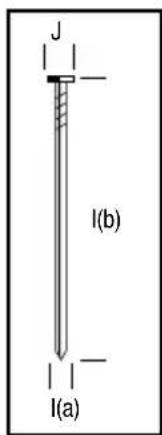
| H Fastener Name DNPT/DNW | ||
| I(a) Dimensions mm 2.8-3.3 mm | ||
| I(b) Dimensions mm 50-90 mm | ||
| J Head/crown 6.7-7.5 mm | ||
| K Magazine capacity 60 | ||
| L Working Ambient Temperature -7°C - 49°C | ||
| M Charger Ref DG-C02-XJ | ||
| N Input Power Source | Input: AC 100-240 Vac, 50/60 Hz, 0.3A Max, Output: 12V 0.5A | |
| O Charging Time in Minutes at 20°C (70f) 120 | ||
| P Charging Voltage | Input: 12V (DC) / Output: 7.2V (DC) | |
| Q Charging Current | Input: 1A / Output: 650mA | |
| R Charger Weight | Adaptor: 78 g / Charger: 132 g | |
| S Battery Weight | 210g | |
| T | Battery Type | DG-B03-XJ (1.6Ah) Ni-MH 6V |
| U | Fuel Cell - Liquid Hydrocarbon:propane/butane | 80ml |
CLOUEUR POUR ENCADREMENT À GAZ - DGN9033
Félicitations !
FRAMING NAGELAPPARAAT OP GAS - DGN9033
Gefeliciteerd!
DRAAG ALTIJD OOGBESCHERMING.
OPSTOPPINGEN VRIJMAKEN
GASDREVEN S∅MPISTOL - DGN9033
Tillykke!
OPLAD KUN KOMPATIBLE DEWALT-BATTERIPAKKER.
S∅M/KLAMME AFSPÆRRING
AFHJÆLPNING AF FASTKLEMTE S∅M
KAASULLA TOIMIVA RUNKONAULAIN - DGN9033
Onnittelut!
TAXYTHTA KYKLIKHS KINHESHS
CHIODATRICE A GAS - DGN9033
Congratulazioni!
GASSDREVEN SPIKERPISTOL - DGN9033
Gratulerer!
1) Gassbeholdere, referansekode: DGFC80MLHP
VEDLIKEHOLDSINTERVALLER
APARAFUSADORA A GÁS - DGN9033
Parabéns!
CLAVADORA PARA ENMARCADO ALIMENTADA POR GAS - DGN9033
¡Enhorabuena!
GASDRIVEN SPIKPISTOL – DGN9033
Grattis!
BULLER- OCH VIBRATIONSDATA
GWOŹDZIARKA GAZOWA - DGN9033
Gratulacje!
NALEŻY NOSIĆ OKULARY I SŁUCHAWKI OCHRONNE
PRZED UŻYCIEM NARZĘDZIA, NALEŻY ZAPOZNAĆ SIĘ Z NINIEJSZĄ INSTRUKCJĄ I DANYMI TECHNICZNYMI PRODUKTU. WSZYSCY OPERATORZY POWINNI ROZUMIEĆ OSTRZEŻENIA I INSTRUKCJE BEZPIECZEŃSTWA I ICH PRZESTRZEGAĆ. NINIEJSZĄ INSTRUKCJĘ NALEŻY ZACHOWAĆ, ABY W RAZIE POTRZEBY MOŻNA BYŁO POWRÓCIĆ DO NIEJ W PRZYSZŁOŚCI.
W PRZYPADKU JAKICHKOLWIEK WĄTPLIWOŚCI, NALEŻY SKONTAKTOWAĆ SIĘ Z PRZEDSTAWICIELEM LUB DYSTRYBUTOREM FIRMY DEWALT.
PLYNOVÁ HŘEBÍKOVAČKA - DGN9033
Blahopřejeme!
PLYNOM POHÁŇANÁ RÁMOVACIA KLINCOVAČKA – DGN9033
Gratulujeme!
TÍPUSÚ GÁZHAJTÁSÚ KERETSZÖGEZŐ DGN9033
Gratulálunk!
PISTOL PNEUMATIC PENTRU STRUCTURI - DGN9033
Felicitări!
INSTRUCTIUNI DE SIGURANTĂ PENTRU ÎNCĂRCAREA SCULEI
| Belgique et Luxembourg België en Luxemburg | DEWALT - Belgium BVBA Egide Walschaertsstraat 16 2800 Mechelen | NL Tel: 32 15 47 37 63 FR Tel: 32 15 47 37 64 | Fax: 32 15 47 37 99 www.dewalt.be enduser.BE@sBDinc.com |
| Danmark D | EWALT Farverland 1B 2600 Glostrup | Tel: 70 20 15 11 Fax: 70 22 49 10 | www.dewalt.dk kundeservice.dk@sbdinc.com |
| Deutschland | DEWALT Richard Klinger Str. 11 65510 Idstein | Tel: 06126-21-1 Fax: 06126-21-2770 | www.dewalt.de infobfge@sbdinc.com |
| Ελλάς | DEWALT (Ελλάς) A.E. ΕΔΡΑ-ΓΡΑΦΕΙΑ : Στράβωνος 7 & Λ. Βουλιαγμένης, Γλυφάδα 166 74, Αθήνα SERVICE : Ημερος Τόπος 2 (Χάνι Αδάμ) – 193 00 Ασπρόπυργος | www.dewalt.gr Greece.Service@sbdinc.com | |
| España | DEWALT Ibérica, S.C.A Parc de Negocios “Mas Blau” Edificio Muntadas, c/Bergadá, 1, Of. A6 08820 El Prat de Llobregat (Barcelona) | Tel: 934 797 400 Fax: 934 797 419 www.dewalt.es respuesta.postventa@sbdinc.com | |
| France | DEWALT 5, allée des Hêtres BP 30084, 69579 Limonest Cedex | Tel: 04 72 20 39 20 Fax: 04 72 20 39 00 | www.dewalt.fr scufr@sbdinc.com |
| Schweiz Suisse Svizzera | DEWALT In der Luberzen 42 8902 Urdorf | Tel: 044 - 755 60 70 Fax: 044 - 730 70 67 | www.dewalt.ch service@rofoag.ch |
| Ireland | DEWALT Calpe House Rock Hill Black Rock, Co. Dublin | Tel: 00353-2781800 Fax: 00353-2781811 | www.dewalt.ie |
| Italia | DEWALT via Energypark 6 20871 Vimercate (MB), IT | Tel: 800-014353 39 039 9590200 Fax: 39 039 9590313 | www.dewalt.it |
| Nederlands D | EWALT Netherlands BV Holtum Noordweg 35 6121 RE BORN, Postbus 83, 6120 AB BORN | Tel: 31 164 283 063 Fax: 31 164 283 200 | www.dewalt.nl |
| Norge | DEWALT Postboks 4613, Nydalen 0405 Oslo | Tel: 22 90 99 10 Fax: 45 25 08 00 | www.dewalt.no kundeservice.no@sbdinc.com |
| Österreich | DEWALT Werkzeug Vertriebsges m.b.H Oberlaaerstrasse 248, A-1230 Wien | Tel: 01 - 66116 - 0 Fax: 01 - 66116 - 614 | www.dewalt.at service.austria@sbdinc.com |
| Portugal | DEWALT Limited, SARL Centro de Escritórios de Sintra Avenida Almirante Gago Coutinho, 132/134, Edificio 14 2710-418 Sintra | Tel: 214 66 75 00 Fax: 214 66 75 80 www.dewalt.pt resposta.posvenda@sbdinc.com | |
| Suomi | DEWALT Tekniikantie 12, 02150 Espoo 02150 Espoo, Finland | Puh: 010 400 43 33 Faksi: 0800 411 340 | www.dewalt.fi asiakaspalvelu.fi@sbdinc.com |
| Sverige | DEWALT Box 94 431 22 Mölndal | Tel: 031 68 60 60 Fax: 031 68 60 08 | www.dewalt.se kundservice.se@sbdinc.com |
| Türkiye | KALE Hirdavat ve Makina A.Ş. Defterdar Mah. Savaklar Cad. No:15 Edirnekapi / Eyüp / İSTANBUL 34050 TÜRKİYE | Tel: 0212 533 52 55 Faks: 0212 533 10 05 www.dewalt.com.tr | |
| United Kingdom | DEWALT, 210 Bath Road; Slough, Berks SL1 3YD | Tel: 01753-567055 Fax: 01753-572112 | www.dewalt.co.uk emeaservice@sbdinc.com |
| Middle East Africa | DEWALT P.O. Box - 17164, Jebel Ali Free Zone (South), Dubai, UAE | Tel: 971 4 812 7400 Fax: 971 4 2822765 | www.dewalt.ae Service.MEA@sbdinc.com |