
MagicSpeed MS 880 - Cruise control DOMETIC - Free user manual and instructions
Find the device manual for free MagicSpeed MS 880 DOMETIC in PDF.

| Product type | Cruise control |
| Brand | Dometic |
| Model | MagicSpeed MS 880 |
| Article number | 9101400078 |
| Operating voltage | 12 V DC |
| Current consumption | max. 10.5 A |
| Operating temperature | -40 °C to +85 °C |
| Activation speed | Approximately 40 km/h |
| Connection type | CAN bus or analog |
| Certifications | 10R 04 1274 |
| Intended use | Cars, motorhomes, vans |
| Main function | Maintaining constant speed |
| Safety | Safety devices: brake, clutch, over-revving, brake lights |
| Delivery contents | Electronic module, cable set, clutch switch, mounting plate, double-sided adhesive tape, cable grommet, cable ties, mounting screws, fuse |
| Optional accessories | Control unit MS-BE3 or MS-BE4, vehicle-specific cable sets |
| Recommended installation | By a specialist if technical knowledge is insufficient |
| Maintenance and cleaning | Cleaning with a damp cloth, do not use sharp objects |
| Warranty | Legal warranty, contact the dealer or the manufacturer's subsidiary |
Frequently Asked Questions - MagicSpeed MS 880 DOMETIC
User questions about MagicSpeed MS 880 DOMETIC
0 question about this device. Answer the ones you know or ask your own.
Ask a new question about this device
Download the instructions for your Cruise control in PDF format for free! Find your manual MagicSpeed MS 880 - DOMETIC and take your electronic device back in hand. On this page are published all the documents necessary for the use of your device. MagicSpeed MS 880 by DOMETIC.
USER MANUAL MagicSpeed MS 880 DOMETIC
natural_image
Black rectangular device with two ports and a white cable with connector, shown against a plain background (no text or symbols visible)MagicSpeed MS880
Installation and Operating Manual
natural_image
Technical line drawing of a welding process with arrows indicating motion (no text or symbols)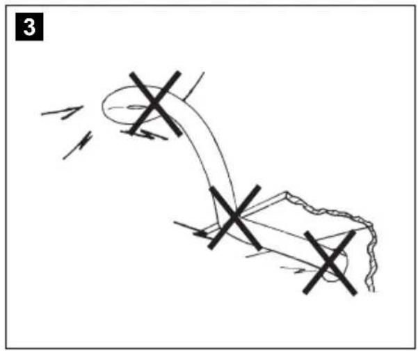
natural_image
Diagram of a mechanical or electrical component with intersecting lines and arrows indicating motion (no text or symbols)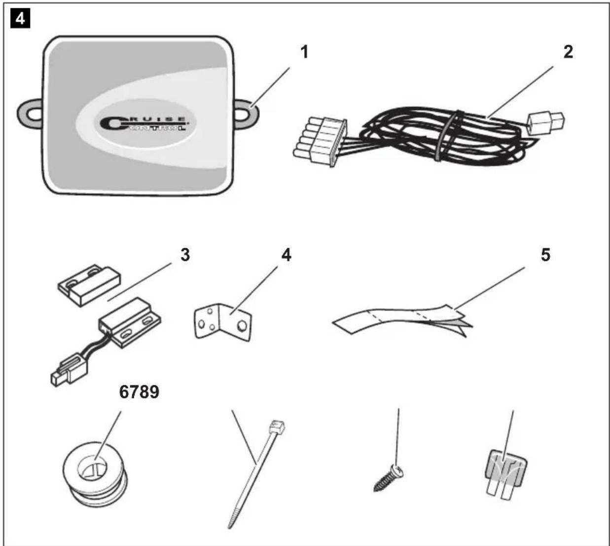
natural_image
Interior view of a car dashboard and steering wheel (no text or symbols visible)
8


DE: 20 IT: 166
EN: 57 NL: 203
FR: 93 DA: 239
ES: 130 SV: 273
9


DE: 22 IT: 168
EN: 58 NL: 205
FR: 95 DA: 240
ES: 131 SV: 274
| bl br ge gn or pk rt sw vt ws | ||||||||||
| DE Blau Braun Gelb Grün Orange Pink Rot Schwarz Violett Weiss | ||||||||||
| EN | Blue | Brown | Yellow | Green | Orange | Pink | Red | Black | Violet | White |
| FR | Bleu | Marron | Jaune | Vert | Orange | Rosa | Rouge | Noir | Lila | Blanc |
| ES | Azul | Marrón | Amarillo | Verde | Naranja | Rose | Rojo | Negro | Violeta | Blanco |
| IT | Blu | Marrone | Giallo | Verde | Arancione | Rosa | Rosso | Nero | Violetto | Bianco |
| NL | Blauw | Bruin | Geel | Groen | Oranje | Roze | Rood | Zwart | Paars | Wit |
| DA | Blå | Brun | Gul | Grøn | Orange | Lyserøde | Rød | Sort | Violet | Hvid |
Please read this instruction manual carefully before installation and first use, and store it in a safe place. If you pass on the product to another person, hand over this instruction manual along with it.
Contents
1 Notes on using the manual 47
2 Safety and installation instructions....47
3 Scope of delivery 50
4 Accessories 51
5 Intended use .... 51
6 Technical description .... 51
7 Installing MagicSpeed 53
8 Connecting the electrical power to MagicSpeed .... 55
9 Installing the control element (accessory) 62
10 Setting procedure....63
11 Synchronising with a CAN-bus connection 65
12 Synchronising with an analogue connection ..... 68
13 Self-diagnosis program 75
14 Testing functions ..... 75
15 Using MagicSpeed....76
16 Maintaining and cleaning MagicSpeed 79
17 Troubleshooting 79
18 Guarantee 79
19 Disposal 79
20 Technical data 80
1 Notes on using the manual

WARNING!
Safety instruction: Failure to observe this instruction can cause fatal or serious injury.

NOTICE!
Failure to observe this instruction can cause material damage and impair the function of the product.

NOTE
Supplementary information for operating the product.
▶ Action: This symbol indicates that action is required on your part. The required action is described step-by-step.
√This symbol describes the result of an action.
BA10: This information refers to another manual included in the scope of delivery where you can find more details, in this case on the BA10.
Fig. 1 5, page 3: This refers to an element in an illustration. In this case, item 5 in figure 1 on page 3.
2 Safety and installation instructions
The manufacturer accepts no liability for damage in the following cases:
● Faulty assembly or connection
● Damage to the product resulting from mechanical influences and excess voltage
- Alterations to the product without express permission from the manufacturer
● Use for purposes other than those described in the operating manual
Please observe the prescribed safety instructions and stipulations from the vehicle manufacturer and service workshops.

WARNING!
Inadequate supply cable connections could result in short circuits, which could have as a consequence that:
- Cable fires occur
● The airbag is triggered
● Electronic control devices are damaged - Electric functions fail (indicators, brake light, horn, ignition, lights)

NOTICE!
To prevent the risk of short circuits, always disconnect the negative terminal of the vehicle's electrical system before working on it. If the vehicle has an additional battery, its negative terminal should also be disconnected.
Please observe the following instructions:
- When working on the following cables, only use insulated cable lugs, plugs and flat push-on receptacles:
- 30 (direct supply from positive battery terminal)
- 15 (connected positive terminal, behind the battery)
- 31 (return line from the battery, earth)
- L (indicator lights left)
-
R (indicator lights right)
Do not use terminal strips. -
Use a crimping tool to connect the cables.
- When connecting to cable 31 (earth), screw the cable
- to the vehicle's earth bolt with a cable lug and a gear disc or
- to the sheet-metal bodywork with a cable lug and a self-tapping screw.
Ensure that there is a good earth connection.
If you disconnect the negative terminal of the battery, all data stored in the volatile memories will be lost.
- The following data must be set again, depending on the vehicle equipment options:
- Radio code
- Vehicle clock
- Timer
- On-board computer
- Seat position
You can find instructions for making these settings in the appropriate operating instructions.
Observe the following installation instructions:

CAUTION!
- Secure the parts installed in the vehicle in such a way that they cannot become loose under any circumstances (sudden braking, accidents) and cause injuries to the occupants of the vehicle.
- Secure any parts of the system covered by the bodywork in such a manner that they cannot be come loose or damage other parts and cables or impair vehicle functions (steering, pedals, etc).
● Always follow the safety instructions of the vehicle manufacturer.
Some work (e.g. on retention systems such as the AIRBAG etc.) may only be performed by qualified specialists.

NOTICE!
- To prevent damage when drilling, make sure there is sufficient space on the other side for the drill head to come out.
● Deburr all drill holes and treat them with a rust-protection agent.
Observe the following instructions when working with electrical parts:

NOTICE!
- When testing the voltage in electrical cables, only use a diode test lamp or a voltmeter.
Test lamps with an illuminant take up voltages which are too high and which can damage the vehicle's electronic system. - When making electrical connections, ensure that:
- they are not kinked or twisted
- they do not rub on edges
- they are not laid in sharp edged ducts without protection.
● Insulate all connections.
- Secure the cables against mechanical wear with cable binders or insulating tape, for example to existing cables.
Please observe the following instructions in particular:
- Observe the applicable legal regulations.
- When driving, make sure no other road users can be injured.
● MagicSpeed is designed as an additional aid; i. e., it does not relieve you of the duty of taking due care when driving.
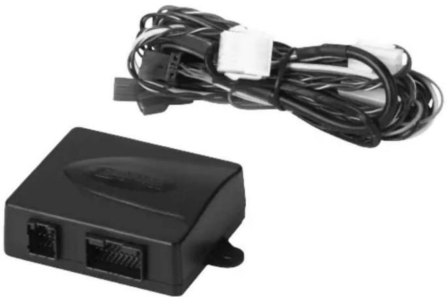
3 Scope of delivery
| No. in fig. 4, quantity Designation page 4 | ||||||
| 1 1 Electronic module | ||||||
| 2 | 1 | C | a | b | l | e |
| 3 1 Clutch switch | ||||||
| 4 1 Fastening plate | ||||||
| 5 1 Double-sided adhesive tape | ||||||
| 6 1 Cable duct | ||||||
| 7 10 Cable binders | ||||||
| 8 2 Fastening screw | ||||||
| 9 | 1 | 3 | A | f | u | s |
For the system to function correctly, you will also require:
● a control element (see chapter "Accessories" on page 51)
● a vehicle-specific cable set
- if applicable, a CAN bus interface (see chapter “Connection options” on page 52)
4 Accessories
Available as accessory (not included in scope of delivery):
Designation Item no.
Control element MS-BE3 9103555852
Control lever MS-BE4 9103555853
Vehicle-specific cable sets –
5 Intended use
MagicSpeed MS880 (item no. 9101400078) can be used as a cruise control.
MagicSpeed is designed as an aid for drivers; it does not relieve you of the duty to take proper care when driving.
MagicSpeed is designed for installation in cars, caravans and vans.
6 Technical description
6.1 Function description
When used as a cruise control, MagicSpeed MS880 keeps the preset speed of your choice as constant as possible. The system compares the actual speed to the set speed and corrects the actual speed as necessary.
The activation speed of the cruise control is about 40 km/h.
MagicSpeed is comprised of an electronic module and a cable set. The electronic module is connected to a control element (accessory, e.g. a lever or infrared steering wheel remote control) with which you can make the required settings. The control element is fitted in the dashboard area.
The system is equipped with various safety features for your protection.
6.2 Connection options
MagicSpeed MS880 can process either a digital speed signal from the CAN bus (CAN bus connection) or an analogue speed signal (analogue connection). A CAN bus connection is not possible in all vehicles with a CAN bus.

NOTE for vehicles with CAN bus
- You can find out whether a CAN bus connection is possible for your vehicle from the vehicle-specific product overview on our homepage, or by calling to enquire (see rear page of the manual for contact data).
- If your vehicle features a CAN bus, but a CAN bus connection is not possible according to the vehicle list, MagicSpeed MS880 must be connected using a analogue connector. This will require the speed signal to be received in analogue form. If the speed signal is only available on the CAN bus in digital form, you will require the CAN bus interface MagicSpeed CBI150 for the installation of MagicSpeed MS880. This converts the digital speed signal from the CAN bus into an analogue one.
- A CAN bus interface is not required for the CAN bus connection.
6.3 Safety features

NOTICE!
If your vehicle has a steering wheel lock, make sure that it is not activated when the key is in the ignition or a gear is selected.
The cruise control is equipped with numerous safety features to switch it off if any of the following situations arise:
● The brake is applied hard
- Pressing the clutch pedal
- Pressing the accelerator and brake pedal at the same time (savior function)
● The ON/OFF button on the control element is pressed
● The engine overspeeds
● Braking to 50 % of the set speed
● Accelerating to 150 % of the set speed
● Increases the engine speed by 150 %
● Decreases the engine speed by 75 %
● The ignition is switched off

NOTE
If MagicSpeed ever fails to react to one of these occurrences, you can always switch off the ignition.
The cruise control also switches off if there are problems with the brake lights, such as:
● Defective brake lights
● A defective fuse
● A loose connection to the brake light switch
In an emergency (e.g. accelerator sticks), you can use the savior function. It is activated by pressing the accelerator and the brake pedal at the same time. It is deactivated when the brake pedal is released. The savior function switches the accelerator to idle electronically, it does not apply the brake. Therefore, keep the brake pedal pressed down until the vehicle stops.
To guarantee safe and economical operation, never use the cruise control in congested traffic or on wet, slippery roads.
7 Installing MagicSpeed

NOTE
If you do not have sufficient technical knowledge for installing and connecting the components in vehicles, you should have a specialist install the system in your vehicle.
7.1 Tools required
For installation and assembly and the electrical connection, you will need the following tools fig. 1, page 3.
To fasten the module and the cables, you may need additional screws and cable binders.
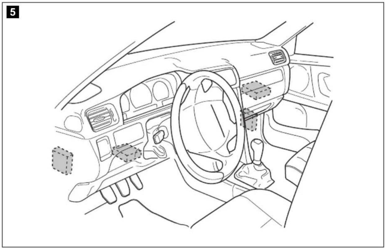
7.2 Installing the electronic module

NOTE
When selecting the installation location, observe the following instructions:
● Install the electronic module
– behind the glove compartment
– behind the footwell on the driver or passenger side
– under the dashboard on the driver side
- not anywhere subject to heat or moisture
- not in the engine compartment
- not near high-voltage components
- not directly next to ventilator nozzles.
● Where possible, use existing holes in the vehicle.

NOTICE!
Before drilling holes, make sure the drill bit will not damage anything on the other side (fig. 2, page 4).
▶ Select a suitable installation location (fig. 5, page 5).
Do not fasten the electronic module before you have decided where to lay the cables.
▶ After finishing assembly, fasten the module to the selected position: screw the electronic module securely to the vehicle with the screws supplied or use double-sided adhesive tape.
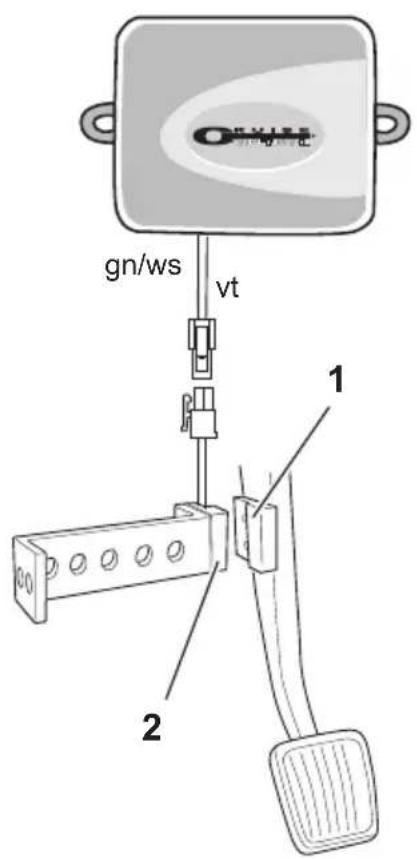
7.3 Installing the clutch switch

NOTE
Check whether your vehicle features a clutch switch. If it does, you do not have to install the clutch switch supplied.
Install the clutch switch as follows (fig. 8, page 7):
▶ Fasten the magnet (fig. 8 1, page 7) to the clutch pedal using double-sided adhesive tape or cable binders.
▶ Fasten the clutch switch (fig. 8 2, page 7) in the footwell using the screws supplied or double-sided adhesive tape.
▶ Connect the 2-pole clutch switch compact plug (fig. 8 2, page 7) with the 2-pole compact plug on the cruise control cable set.

NOTE
On vehicles with manual transmission, you can use the clutch switch to prevent engine overspeed. The cruise control switches off automatically when you press down the clutch.
8 Connecting the electrical power to MagicSpeed
8.1 Laying and connecting the cable set
Please note the following:
- To prevent damage to the cables when laying them, ensure that they are far enough away from hot or moving vehicle components (exhaust pipes, drive shafts, light systems, fans, heater etc.).
- Wrap insulating tape around every connection on the cable (even inside the vehicle).
- When laying the cables, make sure:
– they are not kinked or twisted
– they do not rub on edges - they are not laid in sharp-edged ducts without protection (fig. 3, page 4).
- Protect every hole you drill against water penetration, e.g. by using a cable with a sealant and by spraying the cable and the the cable sleeve with sealant.
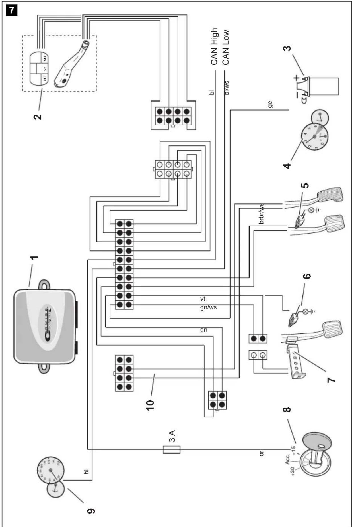
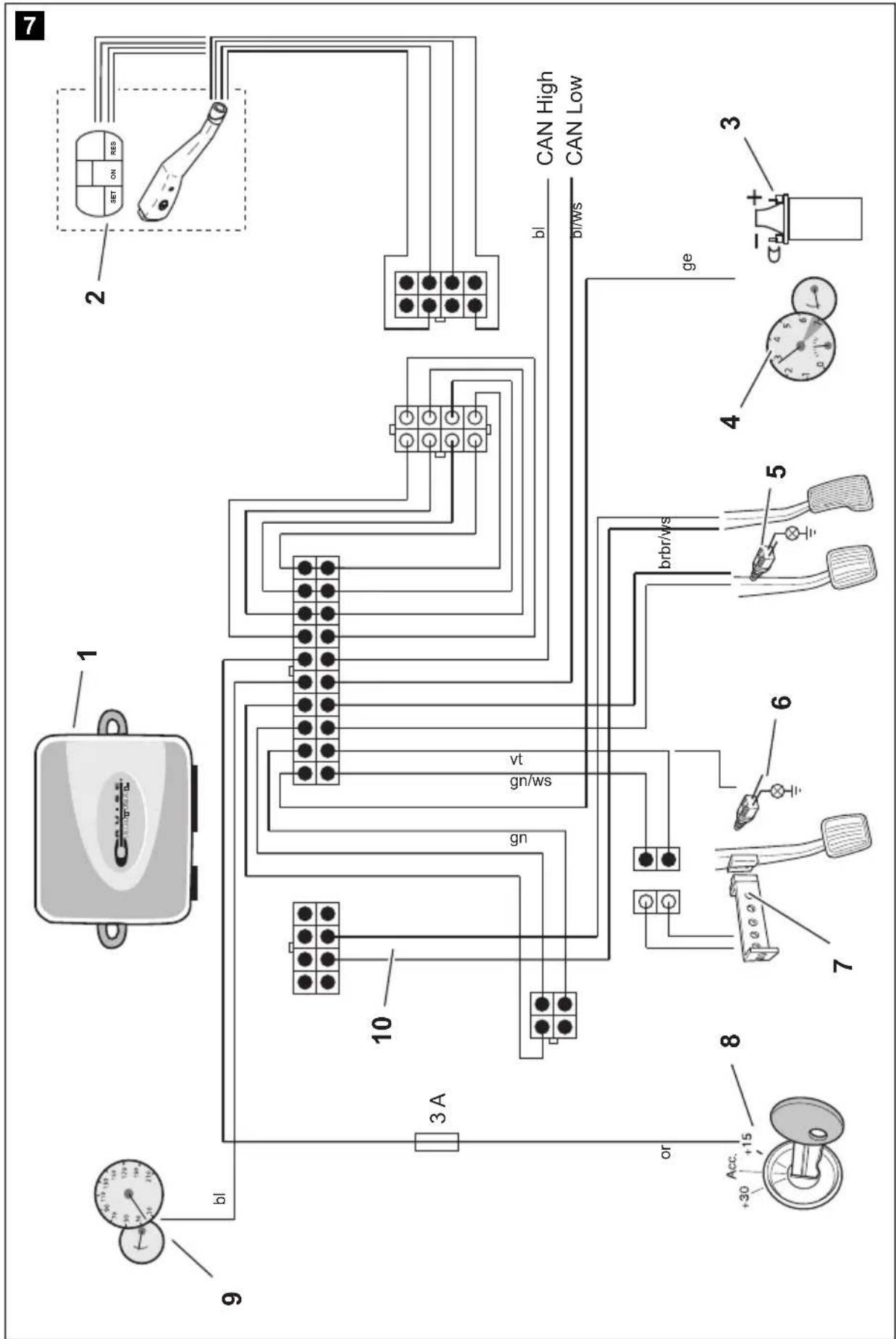
You will find a summary of the wiring in fig. 7, page 6.
No. Component
1 Electronic module
2 Control element
3 Ignition coil
4 Engine speed signal
5 Brake light switch
6 Original clutch switch
7 Clutch switch
8 Ignition
9 Travel speed signal
10 Vehicle-specific cable set (not included)
Orange

NOTICE!
Make sure the ignition is switched off. Otherwise a fuse may blow.
▶ Connect the orange cable to a connected positive terminal (terminal 15).
▶ Use a voltmeter to check whether the selected positive terminal carries the full operating voltage of 12 V and that the orange cable carries no voltage when the ignition is off.
This test is usually done at the fuse box.

NOTICE!
Do not connect the orange cable to the voltage supply for the vehicle accessories (ACC).
Green
▶Insulate the green cable. This cable is not needed. The required earth signal is taken from the accelerator cable set.
Green/white and violet

NOTE
With a CAN bus connection, these cables are only connected when there is no clutch signal on the CAN bus in your vehicle. See also the information in the vehicle-specific product overview at www.dometic-waeco.com/MS880.
Alternatively, you can connect the purple cable with:
- a clutch switch
● the control lamp for the activated parking brake
● (automatic transmission only): the control lamp for park or neutral
You can connect the clutch switch supplied or the vehicle's original clutch switch (if available) to the green/white and purple cable.
Using the clutch switch supplied
▶ Install the clutch switch as described in chapter “Installing the clutch switch” on page 55.
Using the original clutch switch
▶Cut off the two-pin plug from the green/white and purple cable.
▶Connect the purple cable with the original clutch switch cable, whose signals change when you apply the clutch pedal.
The purple cable can process the following changes:
- Connect to earth
- From earth to
- From earth to +12 V
- From +12 V to earth
▶Insulate the green/white cable.
This cable is not required when using an original clutch switch.
Twisted cable pair (blue and blue/white)

NOTE
- Both these cables are only connected when there is a CAN bus connection.
They are not required for analogue connection. In this case, insulate the ends and store them. - Do not mix up the cables. Otherwise the cruise control will not function.
▶ Connect the blue cable (P3) to CAN high.
▶ Connect the blue/white cable (P2) to CAN low.

NOTE
For a CAN bus connection, all cables in the cable set are now connected. You can now install the control element, see chapter "Installing the control element (accessory)" on page 62.
In this case, insulate the ends of the remaining four cables and store them.
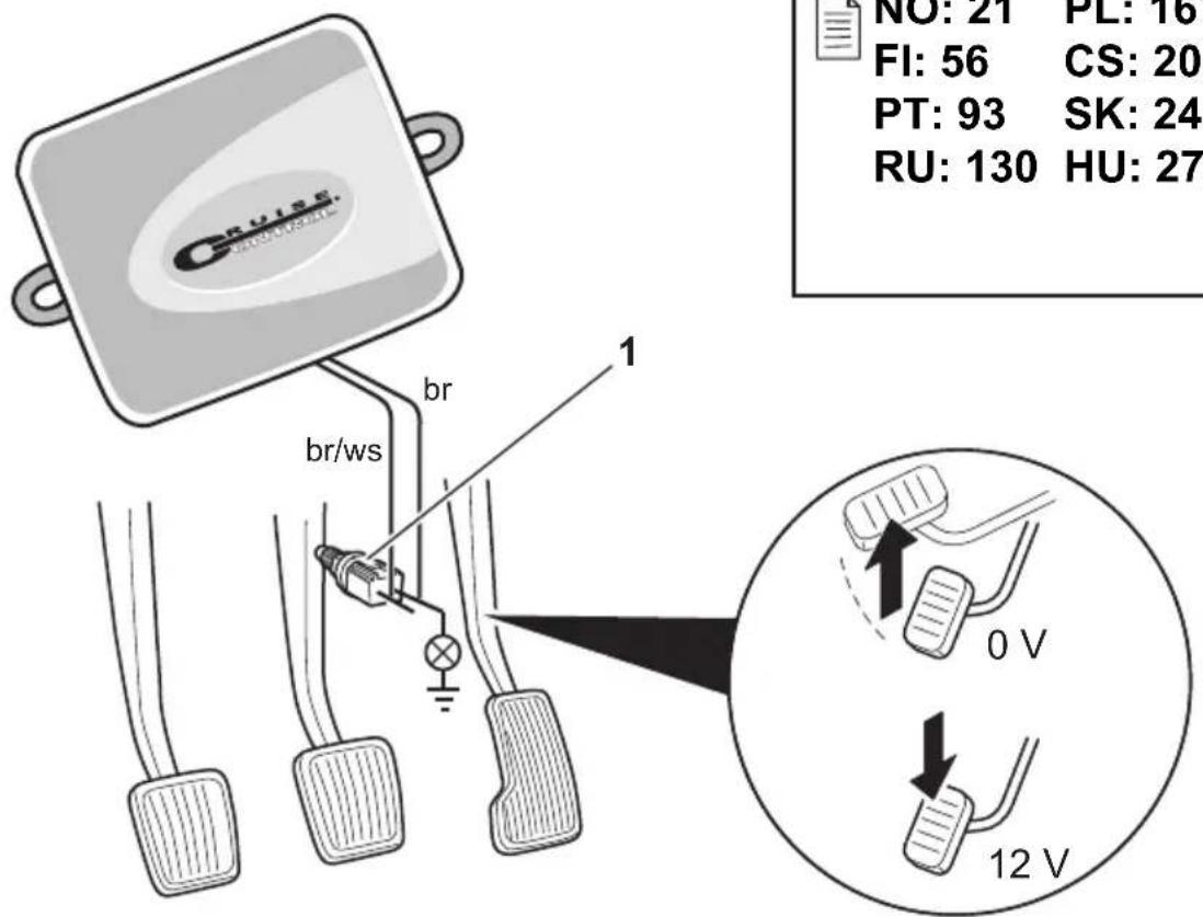
Brown and brown/white

NOTE
Both these cables must only be connected when there is an analogue connection.
They are not required for the CAN bus connection. In this case, insulate the ends and store them.
▶Connect the brown cable and the brown/white cable to the brake light switch (fig. 9 1, page 7).
If there are more than two cables leading from the brake light switch, this is how to identify the two cables you need:
▶Use a voltmeter to measure the voltage on the cables.
One of the two original cables on the brake light switch should have a permanent positive voltage (terminal 30, 12 V) or a connected positive voltage (terminal 15).
The second original cable should have a voltage of +12 V when the brake is applied. As soon as the brake pedal is released, no more voltage should be on that cable.
If you cannot measure a full +12 V on the brake light switch, you vehicle probably has a digital brake system.
In this case, connect the two cables as follows:
▶ Connect the brown/white cable to a fuse-protected, connected positive terminal (terminal 15).
▶Connect the brown cable to the original cable leading to the brake lights.
The voltage on this cable is +12 V with the brake applied, and 0 V with the brake released. You will find these cables directly at the rear lights or in the wiring harness at the rear of the vehicle.
Yellow and blue

NOTE
Both these cables are only connected when there is an analogue connection.
They are not required for the CAN bus connection. In this case, insulate the ends and store them.
The yellow cable and the blue cable are for connection to the travel speed and engine speed signals respectively:
Blue:
Records the engine or travel speed signal with a voltage between 1.5 V and 24 V and a frequency between 6 Hz and 8.5 kHz.
Use the blue cable for speed signals whose voltage and frequency are within above-mentioned ranges.
- Yellow:
Records the engine speed signals with a voltage between 6 V and 250 V and a frequency between 6 Hz and 488 Hz.
Use the yellow cable to record engine speed signals with a voltage of more than 20 V or when engine overspeed protection is required.

NOTE
The signal input depends on the vehicle's transmission.
When connecting the blue and yellow cables, there are various parameters to take into account, which are described in the following sections:
- Which signal input do you wish to use (page 60)?
- Do you need engine overspeed protection (page 61)?
- Does your vehicle have automatic transmission (page 61)?
- Does your vehicle have manual transmission (page 61)?
- Where do you wish to record the speed (Diagnostic manual)?
- Where do you wish to record the engine speed (Diagnostic manual)?
● What are the voltage and frequency of the signal (Diagnostic manual)?

NOTE
You can find a diagnostics manual on our homepage.
Selecting the signal input
There are two ways to record a reference signal for the cruise control:
- Speed signal
The travel speed signal indicates the actual travel speed.
The travel speed signal must be used for vehicles with automatic transmission.
If you use the travel speed signal for vehicles with manual transmission, you must install a deactivation system to prevent engine overspeed (see chapter "Using engine overspeed protection" on page 61).
● Engine speed signal (rpm)
The engine speed signal indicates the engine speed in rpm.
The cruise control can identify the travel speed using the engine speed as long as you do not shift gear.
The engine speed signal is only suitable for vehicles with manual transmission. You must install a switch-off system to prevent engine over-speed (see chapter "Using engine overspeed protection" on page 61).
Using engine overspeed protection

NOTICE!
On vehicles with manual transmission, an engine overspeed protection must be installed.
If a travel speed signal is used as a signal source on vehicles with manual transmission, there must be an engine overspeed protection system in order to prevent damage to the engine.
If you press the clutch while the cruise control is activated, the cruise control must automatically switch off as the engine may otherwise be damaged.
There are two types of engine overspeed protection system:
- If you use the blue cable to transmit the speed signal, you can connect the yellow cable to transmit the engine speed and therefore ensure the engine is protected.
- If there is no engine speed signal, you can use the clutch switch. Install the clutch switch on the clutch pedal (fig. 8 1, page 7) so that the cruise control switches off automatically when the clutch pedal is pressed.
Vehicles with automatic transmission

NOTICE!
Never use an engine speed signal. Otherwise the system will not switch off when the transmission declutches. The engine could overrun and be damaged!
No additional overspeed protection is required for vehicles with automatic transmission.
▶ Connect the blue cable to transmit the speed signal.
Vehicles with manual transmission
▶ Connect the blue cable to the travel speed signal.
▶ Connect the yellow cable as overspeed protection using the engine speed signal or the clutch switch.
Alternatively, you can:
- Connect the blue cable to the engine speed signal, or
- Connect the yellow cable to the negative terminal end of the ignition coil (terminal 1).
With this solution, no additional overspeed protection is required because the engine speed is monitored by the speed regulator. If you use the engine speed signal, the activation speed of the speed regulator depends on the gear the vehicle is currently in.
8.2 Connecting the vehicle-specific cable set
You must connect the electronic module to the accelerator pedal using a vehicle-specific cable set (not supplied).

NOTICE! Risk of damage!
Do not connect the green cable of the main wiring harness to the earth. The earth connection is made via the accelerator cable set.
▶Cut the the original connection of the accelerator pedal.
▶Connect one end of the vehicle-specific cable set to the accelerator pedal.
▶ Connect the other end of the vehicle-specific cable set to the loose end of the original connection.
▶ Insert the 8-pin plug into the appropriate socket on the electronic module.
9 Installing the control element (accessory)
A number of different control elements (such as MS-BE3 or MS-BE4) are available for maximum user convenience, depending on your requirements.
▶Read the instructions enclosed with your control element carefully before assembly.
10 Setting procedure
The procedure remaining after installation and connection depends on the type of connection.
For CAN bus connections (connection to the CAN bus) you must perform the following steps:
- To synchronise the system for CAN bus connection, see chapter “Synchronising with a CAN-bus connection” on page 65
- To check the system connection, see chapter "Testing MagicSpeed (diagnosis mode)" on page 70
- To test the system: see chapter "Testing functions" on page 75
For analogue connections (analogue speed signal) you must perform the following steps:
- To synchronise the system for analogue connection, see chapter “Synchronising with an analogue connection” on page 68
- Perform pedal test, see chapter "Adjusting the accelerator pedal manually" on page 69
- To check the system connection, see chapter “Testing MagicSpeed (diagnosis mode)” on page 70
- Start automatic mode, see chapter "Starting automatic mode" on page 73
- Set the control sensitivity (if necessary), see “Setting the control sensitivity (GAIN mode)” in the diagnostics manual on our homepage
- To test the system: see chapter "Testing functions" on page 75
STANDARD OPERATION
- Ignition ON
- Press ON/OFF button on the control module
- Press and hold down the brake pedal
- Press the SET button four times
Setup Mode
- Press and hold down the brake pedal
Press the SET button once
- Release the brake pedal
- Press and hold down the brake pedal
Press the SET button twice
• Release the brake pedal
- Press and hold down the brake pedal
- Press the SET button three times
- Release the brake pedal
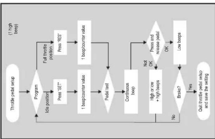
flowchart
graph TD
    A["Throttle pedal setup"] --> B{Program}
    B -->|Idle position| C["Press 'SET'"]
    B -->|Full throttle position| D["Press 'RES'"]
    C --> E["1 beep/counter value"]
    D --> F["1 beep/counter value"]
    E --> G{Pedal test}
    F --> G
    G -->|No| H["Continuous beep"]
    G -->|Yes| I{Brake?}
    H --> J["High or low + high beeps"]
    I -->|No| K["Quit throttle pedal setup and save the setting"]
    J --> L["Press and release pedal"]
    K --> M["Low beeps"]
    L --> N["OK"]
    M --> N
    N --> O["Not OK"]
    O --> H
- Press and hold down the brake pedal
press the SET button four times
- Release the brake pedal
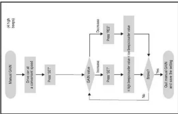
flowchart
graph TD
    A["Manual GAIN"] --> B["Drive car at a convenient speed"]
    B --> C["Press "SET""]
    C --> D{GAIN value}
    D -->|Increase| E["Press "SET""]
    D -->|Decrease| F["Press "RES""]
    E --> G["n high beeps/counter value n low beeps/counter value"]
    F --> G
    G --> H{Brake?}
    H -->|No| D
    H -->|Yes| I["Quit manual GAIN and save the settling"]
    I --> D
    style A fill:#ccc,stroke:#333
    style B fill:#ccc,stroke:#333
    style C fill:#ccc,stroke:#333
    style D fill:#ccc,stroke:#333
    style E fill:#ccc,stroke:#333
    style F fill:#ccc,stroke:#333
    style G fill:#ccc,stroke:#333
    style H fill:#ccc,stroke:#333
    style I fill:#ccc,stroke:#333
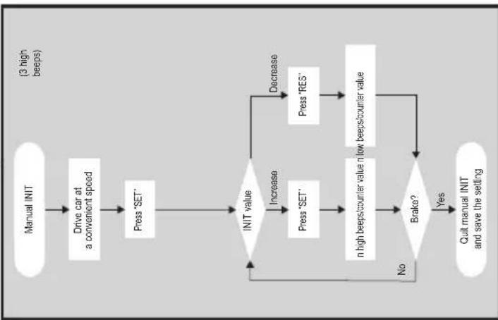
flowchart
graph TD
    A["Manual INIT"] --> B["Drive car at a convenient speed"]
    B --> C["Press 'SET'"]
    C --> D{INIT value}
    D -->|Increase| E["Press 'SET'"]
    D -->|Decrease| F["Press 'RES'"]
    E --> G["n high beeps/counter value n low beeps/counter value"]
    F --> G
    G --> H{Brako?}
    H -->|No| D
    H -->|Yes| I["Quit manual INIT and save the setting"]
    I --> D
    style A fill:#f9f,stroke:#333
    style B fill:#f9f,stroke:#333
    style C fill:#f9f,stroke:#333
    style D fill:#ccf,stroke:#333
    style E fill:#ccf,stroke:#333
    style F fill:#ccf,stroke:#333
    style G fill:#ccf,stroke:#333
    style H fill:#ccf,stroke:#333
    style I fill:#ccf,stroke:#333
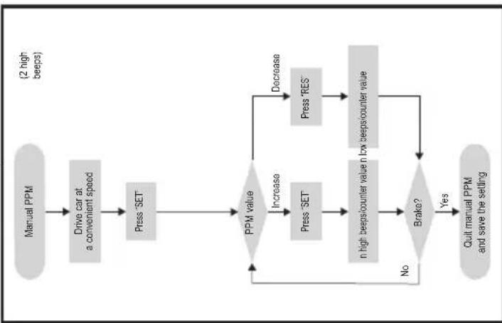
flowchart
graph TD
    A["Manual PPM"] --> B["Drive car at a convenient speed"]
    B --> C["Press 'SET'"]
    C --> D{PPM value}
    D -->|Increase| E["Press 'SET'"]
    D -->|Decrease| F["Press 'RES'"]
    E --> G["n high beeps/counter value n low beeps/counter value"]
    F --> G
    G --> H{Brako?}
    H -->|No| D
    H -->|Yes| I["Quit manual PPM and save the setting"]
    I --> D
    style A fill:#ccc,stroke:#333
    style I fill:#ccc,stroke:#333

flowchart
graph TD
    A["Throttle pedal setup"] --> B{Program}
    B -->|Idle position| C["Press 'SET'"]
    B -->|Full throttle position| D["Press 'RES'"]
    C --> E["1 beep/counter value"]
    D --> F["1 beep/counter value"]
    E --> G{Pedal test}
    F --> G
    G -->|No| H["Continuous beep"]
    G -->|Yes| I{Brake?}
    H --> J["High or low + high beeps"]
    I -->|Yes| K["Quit throttle pedal setup and save the setting"]
    I -->|No| L["End"]
    J --> M["Press and release pedal"]
    K --> N["Low beeps"]
    L --> O["End"]
    style A fill:#f9f,stroke:#333
    style B fill:#ccf,stroke:#333
    style C fill:#cfc,stroke:#333
    style D fill:#fcc,stroke:#333
    style E fill:#ffc,stroke:#333
    style F fill:#cff,stroke:#333
    style G fill:#ffc,stroke:#333
    style H fill:#cfc,stroke:#333
    style I fill:#cfc,stroke:#333
    style J fill:#cfc,stroke:#333
    style K fill:#cfc,stroke:#333
    style L fill:#cfc,stroke:#333
    style M fill:#fcc,stroke:#333
    style N fill:#fcc,stroke:#333
Quitting setup mode: Press and hold down the brake pedal; press the SET button four times (you will hear one long beep)
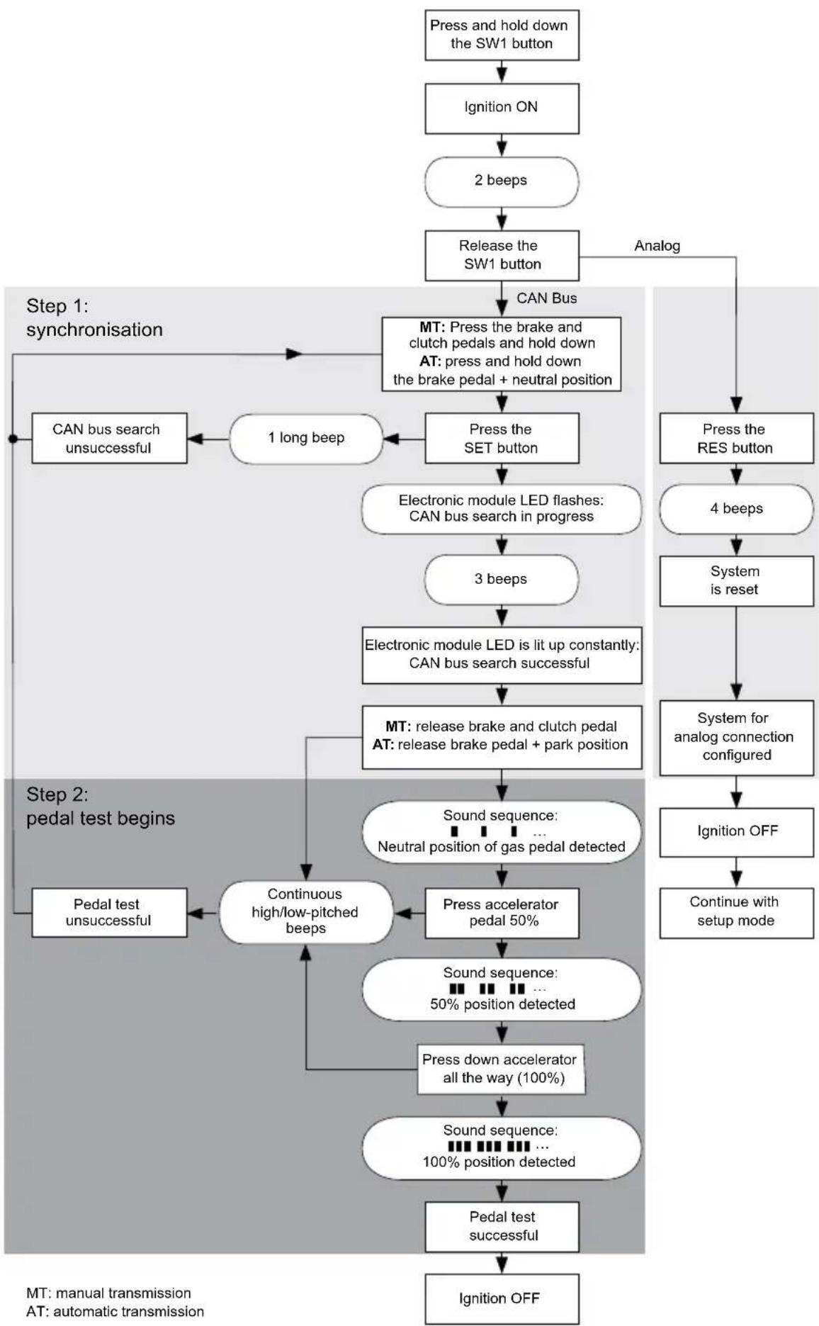
11 Synchronising with a CAN-bus connection
Step 1 (synchronisation)
▶Press and hold the SW1 button on the rear of the electronic module.
▶Switch on the ignition.
√You will hear two high-pitched signals.
▶Let go of the SW1 button.
▶ Manual transmission: Apply the brake and clutch pedal and keep both pressed down.
▶ Automatic transmission: Apply the brake pedal and hold it down. Put the gear into neutral.
▶Press the SET button on the control element.
√The LED on the electronic module starts flashing.
√The electronics start to synchronise with the vehicle automatically.
√ When the synchronisation is complete, you will hear three high-pitched signals.
√The LED on the electronic module lights up permanently.
▶ Manual transmission: Remove your foot from the brake and the clutch pedal.
▶ Automatic transmission: Remove your foot from the brake pedal and put the gear into neutral.

NOTE
If you do not hear three high-pitched signals, check the connections to CAN high (blue cable) and CAN low (blue/white cable) and check whether MagicSpeed MS880 can be connected to the CAN bus in your vehicle according to the vehicle list.
√ After successful synchronisation, the electronics automatically continue with step 2 (pedal test).
Step 2 (accelerator pedal test)
▶ Press the accelerator pedal slowly as far as it will go and let it return the same way slowly as far as the neutral position.
√ While this happens, you will hear acoustic signals which signify the various positions:
- Neutral position (idle): ■ ■ ■ ...
- 50 % position: ■■ ■■ ■■ ...
- 100 % position: ■■■ ■■■ ■■■ ...

NOTE
- If a low-pitched signal does not sound or you hear a high-pitched signal during the pedal test, this step has failed and programming must be repeated from step 1.
- Some accelerator pedals do not provide sufficient electric signals when fully pressed down. In this case, only press the pedal approx. three-quarters of the way down in step 2, as otherwise the test will not be successful.
Step 3 (quit synchronisation)
▶Switch the ignition off.
√Normally, your cruise control should be ideally preset for your vehicle.
Refer to the figure on page 67 for a summary of the CAN bus connection and pedal test.
flowchart
graph TD
    A["Press and hold down the SW1 button"] --> B["Ignition ON"]
    B --> C["2 beeps"]
    C --> D["Release the SW1 button"]
    D --> E["CAN Bus"]
    E --> F["MT: Press the brake and clutch pedals and hold down\nAT: press and hold down the brake pedal + neutral position"]
    F --> G["Press the SET button"]
    G --> H["Electronic module LED flashes:\nCAN bus search in progress"]
    H --> I["3 beeps"]
    I --> J["Electronic module LED is lit up constantly:\nCAN bus search successful"]
    J --> K["MT: release brake and clutch pedal\nAT: release brake pedal + park position"]
    K --> L["Sound sequence: <br>Neutral position of gas pedal detected"]
    L --> M["Press accelerator pedal 50%"]
    M --> N["Continuous high/low-pitched beeps"]
    N --> O["Pedal test unsuccessful"]
    O --> P["Ground"]
    Q["Step 1: synchronisation"] --> F
    R["Step 2: pedal test begins"] --> L
    S["Step 3: ignition OFF"] --> T["Continue with setup mode"]
    U["PTM: manual transmission\nAT: automatic transmission"] --> V["End"]
12 Synchronising with an analogue connection

NOTE
Before you can configure the settings, you must switch the system to analogue connection.
12.1 Switching MagicSpeed to analogue connection
▶Press and hold the SW1 button on the rear of the electronic module.
▶Switch on the ignition.
√You will hear two high-pitched signals.
▶Let go of the SW1 button.
▶Press the RES button on the control element.
√ The electronic module is switched from the “CAN bus connection” setting to the “Analogue connection” setting.
√ When the switchover is complete, you will hear four high-pitched signals.
▶Switch the ignition off.
12.2 Starting setup mode

NOTE
- To begin one of the adjusting and teach modes you must always carry out the following procedure.
- For automatic mode (page 73), you first have to start the motor.
- For any of the other modes, you first simply have to switch the ignition off and on again.
To start setup mode, proceed as follows:
▶Depending on the mode, do one of the following:
- For automatic mode: start the motor.
- For the other modes: switch the ignition off and on again.
▶Press the ON/OFF button on the control element.
▶Apply the brake within one minute and hold it down.
▶Press the setup button four times in rapid succession.
▶Release the brake.
√You will hear four acoustic signals.
√You are now in setup mode and can set the cruise control.
12.3 Adjusting the accelerator pedal manually
In this mode, the accelerator pedal parameters are taught to the electronic module manually.

NOTE
- After each programming step is successfully completed, it is confirmed by an intermittent tone of the same pitch. If there is an intermittent tone of differing pitch, this step has failed and the programming must be repeated from step 1.
- Some accelerator pedals do not provide sufficient electric signals when fully pressed down. In this case, only press the pedal approx. three-quarters of the way down, as otherwise programming will not be successful.
Step 1
▶Start setup mode (chapter "Starting setup mode" on page 68).
▶Apply the brake and hold it down.
▶Press the RES button once.
√An low-pitched acoustic signal sounds.
▶Release the brake.
Step 2
▶ In neutral position (accelerator pedal is not pressed down), press the SET-button once.
√The idling value is programmed.
Step 3
▶ Press the accelerator pedal down as far as it will go and press the RES button once.
Step 4
▶ Press the accelerator pedal slowly as far as it will go and let it return the same way slowly as far as the neutral position.
√A constant signal sounds during this procedure.
Step 5
When steps 1 to 4 have been successfully completed:
▶Activate the brake.
√The set values are stored permanently in the electronic module.
√ Teach mode will be exited.
12.4 Testing MagicSpeed (diagnosis mode)
The cruise control has a self-diagnosis mode. The self-diagnosis mode is divided into three sections (modes A, B and C) and tests all components and functions of the cruise control.
Before you start self-diagnosis, check again that all the cables are correctly connected.
▶Apply the handbrake.
▶Shift the gear to neutral, or to neutral or park if it is automatic.
▶Press down the SET button on the control element and hold it.
▶Switch on the ignition.
√An audible signal sounds as long as you hold the SET button.
▶Let go of the SET button.
√The audible signal stops.
If you hear another signal within a second of letting go of the SET button, a control input is activated, for example the clutch switch.
▶Check the cable connections to find the control input.

NOTE
The diagnosis modes are for testing all components and functions of the cruise control. The cruise control uses an internally generated reference signal to test the electric module in diagnosis mode B.
If the cruise control does not work after diagnosis mode B is completed, there is generally a problem recording the travel speed signal.
Diagnosis mode A
Diagnosis mode A tests the electronic components and electrical connections.
The LED in the electronic module and the integrated buzzer simultaneously show that the electric wiring and the components are working properly. When checking the components later, it is not necessary to uncover the electronic module, because the audible signals accompany the optical ones.
You will receive confirmation from the LEDs and the buzzer when you activate the following signals:
- SET button
- RES button
- Brake
- Clutch switch
● Neutral safety switch
● Travel speed signal in teach mode
● Engine speed signal in teach mode
The audible and visible signals are emitted for a maximum of ten seconds per input to ensure that other messages are not suppressed.
If you activate one of the functions above and do not hear or see a signal:
▶Check the electric wiring.
Diagnosis mode B
Diagnosis mode B tests the function of the accelerator.
▶Apply the handbrake.
▶Shift the gear to neutral, or to neutral or park if it is automatic.
▶Press and hold down the SET button.
▶Start the engine.
▶When the engine is running, let go of the SET button.
▶Now switch on the speed controller using the ON/OFF button on the control element.
√The LED in the control element lights up.

NOTICE!
Do not let the engine overrun.
▶ To increase the engine speed press and hold down the SET button.
√The engine speed slowly increases.
▶ To reduce the engine speed press and hold down the RES button.
√The engine speed slowly drops.
▶ To drop the engine speed back down to the idle speed again,
- apply the brake or clutch, or
- press the ON/OFF button on the control element.
▶To quit diagnosis mode, switch off the ignition.

NOTE
For safety reasons, the engine speed can only be increased by 66 % of the maximum value.
Diagnosis mode C
Diagnosis mode C tests the travel speed or engine speed signal.
▶Press and hold down the SET button.
▶Start the engine.
▶When the engine is running, let go of the SET button.
▶Drive your vehicle at a speed of around 50 km/h.
▶ Now switch on the cruise control using the ON/OFF button on the control element.
√The LED in the electronic module flashes and an audible signal sounds once per second.
▶Bring the vehicle to a stop.
▶Switch the ignition off.
√The diagnosis mode has been quit.
12.5 Starting automatic mode
In automatic mode, the PPM and GAIN parameters are automatically synchronised with your vehicle. You can still fine-tune both parameters anytime.
▶Start setup mode (chapter "Starting setup mode" on page 68).
▶Apply the brake and hold it down.
▶Press the RES button twice.
√You will hear two low-pitched signals.
▶Release the brake.
√You will hear two high-pitched signals.

NOTE
If you hear more than two signals, repeat the procedure.
▶ Drive the vehicle at a speed of 70 km/h to allow the PPM and GAIN parameters to be set automatically.
▶Press the SET button.
√The cruise control switches itself on.
If the cruise control does not take on the speed gently or the save value is not applied:
▶ Press the SET button again to increase the value or
▶ ... press the RES button to decrease the value.
√You will hear a signal each time you press the button.
The current value is indicated by the number of beeps (3 - 14 beeps). The factory setting is 5 beeps.
▶Apply the brake to save the set values (PPM and GAIN).
√Normally, your cruise control should be ideally preset for your vehicle.
▶Quit setup mode (chapter "Quitting setup mode" on page 74).
▶You can now use MagicSpeed MS880.

NOTE
If, during operation, you notice that the vehicle reacts too slowly or too suddenly, or the speed is not being regulated correctly, you must set the control sensitivity manually (see “Setting the control sensitivity (GAIN mode)” in the diagnostics manual on our home-page).
12.6 Quitting setup mode
To quit setup mode, proceed as follows:
▶Stop the vehicle.
▶Apply the brake and hold it down.
▶Press the SET button four times.
√You will hear a long signal.
√You have now quit setup mode.
13 Self-diagnosis program
MagicSpeed MS880 has a self-diagnosis program. After activation in driving mode, the cruise control or the speed limiter (variable) deactivates itself automatically if there is a fault. In this case, the cause of the fault is indicated by a series of high-pitched beeps.
The cruise control or speed limiter switches off:
- if one of the control element buttons is jammed or held down for longer than 20 s. There is one high-pitched beep.
- if the current speed increases unusually (> 9 km/h per second). There are two high-pitched beeps.
- if the current speed is less than 33 km/h. There are three high-pitched beeps.
- if the current speed is more than 250 km/h. There are four high-pitched beeps.
- if the current speed falls below 75 % of the stored speed (e.g. going uphill). There are five high-pitched beeps.
- if the current speed increases to over 150 % of the stored speed (e.g. going downhill). There are six high-pitched beeps.
- if there is a fault in the accelerator pedal cable set. There are seven high-pitched beeps.
- if the engine speed increases unusually. There are eight high-pitched beeps.

NOTE
You can find a diagnostics manual on our homepage.
14 Testing functions
14.1 Testing the cruise control function

NOTE
The lowest speed at which the cruise control works is around 40 km/h.
▶Start the vehicle.
▶ Switch on the cruise control by pressing the ON/OFF button on the control element briefly (< 1 sec).
√You will hear two low-pitched signals.
√The LED on the control element lights up in green.
▶Drive at a speed of 40 to 50 km/h.
▶Press the SET button to configure the preferred speed.
√The cruise control gently takes on the speed and maintains the driving speed at a constant level.
14.2 Setting the sensitivity
If the cruise control does not switch on gently and the speed increases or decreases during control mode, you can adjust the sensitivity of the cruise control (see page 68):
- If the cruise control works too suddenly or the vehicle speeds up too much, you must decrease the GAIN value (see “Setting the control sensitivity (GAIN mode)” in the diagnostics manual on our homepage).
- If the cruise control works too slowly or the vehicle slows down too much, you must increase the GAIN value (see “Setting the control sensitivity (GAIN mode)” in the diagnostics manual on our homepage).
15 Using MagicSpeed
MagicSpeed is controlled using the buttons on the control lever.
15.1 Using the cruise control
ON/OFF button
▶ Press the ON/OFF button once briefly (< 1 sec) to switch on the cruise control.
√You will hear two low-pitched signals.
√The LED on the control element lights up.
▶Press the ON/OFF button again to switch the cruise control off.
√The LED on the control element goes out.
SET button
Use the SET button to save a preferred speed in the cruise control.
▶Press the SET button and let go again immediately to set the speed you are currently driving.
This set speed is maintained until:
– you apply the brake or clutch pedal,
- you switch off the device with the ON/OFF button,
– the vehicle slows down to below the lower activation speed,
– the speed drops by more than 25 % on a slope.
▶Press the SET button continuously to accelerate the vehicle.
When you let go of the SET button, the cruise control records the current speed and saves it.
RES button
Press the RES button to recall the last saved speed when:
- you have switched on the cruise control using the ON/OFF button,
- you do not apply the brake or clutch pedal,
- you do not switch off the ignition in the meantime,
● the vehicle does not slow down to below the lower activation speed,
● the current speed is not less than 50 % of the saved value.
▶Press the RES button and let go again immediately to recall the last saved speed.
Accelerating and decelerating
If the cruise control is activated, you have the option of fine tuning it.
This allows you to adapt the speed of the vehicle precisely to suit traffic conditions or speed limits.
▶ Touch the SET button to increase the speed by 1.5 km/h.
▶ Press the SET button for 1 second to increase the speed by 10 km/h.
▶ Touch the RES button to decrease the speed by 1.5 km/h.
▶ Press the RES button for 1 second to reduce the speed by 10 km/h.
If, for example, you wish to increase the speed by around 5 km/h, touch the SET button three times.

NOTE
If you wish to decrease the set speed sharply, do not use the RES button.
Use the ON/OFF button, the brake or the clutch and then press the SET button to set the speed you prefer.
15.2 Resetting the software
▶Press and hold the SW1 button on the rear of the electronic module.
▶Switch on the ignition.
√You will hear two high-pitched signals.
▶Let go of the SW1 button.
▶Press the SET button on the control element.
√The LED on the electronic module starts flashing.
√The electronics start to synchronise with the vehicle automatically and reset the software to its status when delivered.
√ After the software is successfully reset, you will hear three signals.
▶Switch the ignition off.
16 Maintaining and cleaning MagicSpeed

NOTICE!
Do not use sharp or hard objects to clean the device as these may damage the device.
▶Clean the components with a damp cloth from time to time.
17 Troubleshooting

NOTE
You can find a diagnostics manual on our homepage.
18 Guarantee
The statutory warranty period applies. If the product is defective, please contact the manufacturer's branch in your country (see the back of the instruction manual for the addresses) or your retailer.
For repair and guarantee processing, please send the following items:
- Defect components
● A copy of the receipt with purchasing date
● A reason for the claim or description of the fault
19 Disposal
▶Place the packaging material in the appropriate recycling waste bins wherever possible.
If you wish to finally dispose of the product, ask your local recycling centre or specialist dealer for details about how to do this in accordance with the applicable disposal regulations.
20 Technical data
| MagicSpeed MS880 | |
| Item number: 9101400078 | |
| Operating voltage: 12 V== | |
| Current consumption: max. 10.5 A | |
| Operating temperature: -40 °C to +85 °C | |
| Certifications: |  10R 04 1274 10R 04 1274 |
6 Description technique
Trin 2 (speedertest)
Dometic Australia Pty. Ltd.
1 John Duncan Court
Varsity Lakes QLD 4227
+61 7 55076000
+61 7 55076001
Mail: sales@dometic-waeco.com.au
AUSTRIA
Dometic Austria GmbH
Commercial : info@dometic.fr
SAV/Technique : service@dometic.fr
HONG KONG
WAECO Impex Ltd.
Suites 2207-2211 · 22/F · Tower 1
The Gateway · 25 Canton Road,
Tsim Sha Tsui · Kowloon
+852 24611386
+852 24665553
Mail: info@dometic-waeco.com.hk
HUNGARY
Dometic Plc. Sales Office
Kerékgyártó u. 5.
H-1147 Budapest
+36 1 468 4400
昌 +36 1 468 4401
Dometic Italy S.r.l.
Via Virgilio, 3
I-47100 Forli
+39 0543 754901
+39 0543 756631
Mail: info@dometic.it
NORWAY
Dometic Norway AS
Skolmar 24
N-3232 Sandefjord
+47 33428450
吕 +47 33428459
Mail: firmapost@waeco.no
POLAND
Dometic Poland Sp. z o.o.
Ul. Puławska 435A
02-801 Warszawa
+48 22 414 32 00
+48 22 414 32 01
Mail: info@dometic.pl
RUSSIA
Dometic RUS LLC
Komsomolskaya square 6-1
107140 Moscow
+7 495 780 79 39
+7 495 916 56 53
Mail: info@dometic.ru
SLOVAKIA
Dometic Slovakia Sales Office Bratislava
Nádražná 34/A
SK-900 28 Ivanka pri Dunaji
+421 2 45 529 680
Mail: bratislava@dometic.com
SPAIN
Dometic Spain S.L.
Avda. Sierra del Guadarrama, 16
E-28691 Villanueva de la Cañada
Madrid
+34 902 111 042
+34 900 100 245
Mail: info@dometic.es
SWEDEN
Dometic Scandinavia AB
Gustaf Melins gata 7
Dometic Switzerland AG
Riedackerstrasse 7a
CH-8153 Rümlang (Zürich)
+41 44 8187171
吕 +41 44 8187191
Mail: info@dometic-waeco.ch
TAIWAN
WAECO Impex Ltd.
Taipei Office
2 FL-3 · No. 56 Tunhua South Rd, Sec 2
Taipei 106
+886 2 27014090
昌 +886 2 27060119
Mail: marketing@dometic-waeco.com.tw
UNITED KINGDOM
Dometic UK Ltd.
Dometic House · The Brewery
Blandford St. Mary
Dorset DT11 9LS
+44 844 626 0133
昌 +44 844 626 0143
Mail: sales@dometic.co.uk
UNITED ARAB EMIRATES
Dometic Middle East FZCO
P. O. Box 17860
S-D 6, Jebel Ali Freezone
Dubai
+971 4 883 3858
+971 4 883 3868
Mail: info@dometic.ae
UNITED STATES OF AMERICA
Dometic Marine Division
2000 N. Andrews Ave. Extension
Pompano Beach, FL 33069 USA
+1 954 973 2477
+1 954 979 4414
Mail: marinesales@dometicusa.com
natural_image
Black rectangular device with two ports and a white cable with connector, shown against a plain background (no text or symbols visible)MagicSpeed MS880
natural_image
Technical line drawing of a welding process with arrows indicating motion (no text or symbols)
natural_image
Diagram of a mechanical or electrical component with directional arrows and cross marks, no readable text or symbols present.

natural_image
Interior view of a car dashboard and steering wheel (no text or symbols visible)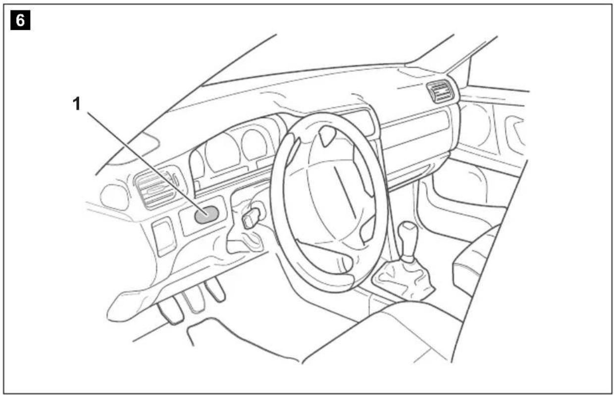
8

NO: 20 PL: 166
FI: 55 CS: 203
PT: 91 SK: 238
RU: 128 HU: 275
9

NO: 21 PL: 167
FI: 56 CS: 205
PT: 93 SK: 240
RU: 130 HU: 277
| bl br ge gn or pk rt sw vt ws | ||||||||||
| SV | Blå Brun Gul Grön Orange Rosa Röd Svart Violett Vit | |||||||||
| NO | Blå | Brun | Gul | Grønn | Oransje | Rosa | Rød | Svart | Fiolett | Hvit |
| FI | Sininen | Ruskea Ke tai- nen | Vihreä | Oranssi | Pinkki | Punainen | Musta | Violetti | Valkoi- nen | Valkoi- nen |
| RU | Синий | Коричневый | Желтый | Зеленый | Оранжевый | Розовый | Красный | Черный | Фиолетовый | Белый |
| PL | Niebieski | Brązowy | Żółty | Zielony | Pomarańcz owy | Różowy | Czerwony | Czarny | Fioletowy | Biały |
| CS | Modrá | Hněda | Żlutá | Zelená | Oranžová | Růžová | Červená | Černá | Fialová | Bílá |
| SK | Modrá | Hnedá | Żltá | Zelená | Oranžová | Ružová | Červená | Čierna | Fialová | Biela |
Dometic Australia Pty. Ltd.
1 John Duncan Court
Varsity Lakes QLD 4227
1800 212121
+61 7 55076001
Mail: sales@dometic-waeco.com.au
AUSTRIA
Dometic Austria GmbH
The Gateway · 25 Canton Road,
Tsim Sha Tsui · Kowloon
+852 24611386
+852 24665553
Mail: info@dometic-waeco.com.hk
HUNGARY
Dometic Plc. Sales Office
Kerékgyártó u. 5.
H-1147 Budapest
+36 1 468 4400
昌 +36 1 468 4401
Dometic Italy S.r.l.
Via Virgilio, 3
I-47100 Forli
+39 0543 754901
+39 0543 756631
Mail: info@dometic.it
NORWAY
Dometic Norway AS
Skolmar 24
N-3232 Sandefjord
+47 33428450
吕 +47 33428459
Mail: firmapost@waeco.no
POLAND
Dometic Poland Sp. z o.o.
Ul. Puławska 435A
02-801 Warszawa
+48 22 414 32 00
+48 22 414 32 01
Mail: info@dometic.pl
RUSSIA
Dometic RUS LLC
Komsomolskaya square 6-1
107140 Moscow
+7 495 780 79 39
+7 495 916 56 53
Mail: info@dometic.ru
SLOVAKIA
Dometic Slovakia Sales Office Bratislava
Nádražná 34/A
SK-900 28 Ivanka pri Dunaji
+421 2 45 529 680
Mail: bratislava@dometic.com
SPAIN
Dometic Spain S.L.
Avda. Sierra del Guadarrama, 16
E-28691 Villanueva de la Cañada
Madrid
+34 902 111 042
+34 900 100 245
Mail: info@dometic.es
SWEDEN
Dometic Scandinavia AB
Gustaf Melins gata 7
Dometic Switzerland AG
Riedackerstrasse 7a
CH-8153 Rümlang (Zürich)
+41 44 8187171
吕 +41 44 8187191
Mail: info@dometic-waeco.ch
TAIWAN
WAECO Impex Ltd.
Taipei Office
9F.-10, No. 1180, Zhongzheng Rd.,
Zhonghe Dist., New Taipei City 23586
+886 2 22237225
昌 +886 2 81926742
Mail: marketing@waeco.com.tw
UNITED KINGDOM
Dometic UK Ltd.
Dometic House · The Brewery
Blandford St. Mary
Dorset DT11 9LS
+44 844 626 0133
昌 +44 844 626 0143
Mail: sales@dometic.co.uk
UNITED ARAB EMIRATES
Dometic Middle East FZCO
P. O. Box 17860
S-D 6, Jebel Ali Freezone
Dubai
+971 4 883 3858
+971 4 883 3868
Mail: info@dometic.ae
UNITED STATES OF AMERICA
Dometic Marine Division
2000 N. Andrews Ave. Extension
Pompano Beach, FL 33069 USA
+1 954 973 2477
+1 954 979 4414
Mail: marinesales@dometicusa.com