Erika 85 - Saw Mafell - Free user manual and instructions
Find the device manual for free Erika 85 Mafell in PDF.


User questions about Erika 85 Mafell
0 question about this device. Answer the ones you know or ask your own.
Ask a new question about this device
Download the instructions for your Saw in PDF format for free! Find your manual Erika 85 - Mafell and take your electronic device back in hand. On this page are published all the documents necessary for the use of your device. Erika 85 by Mafell.
USER MANUAL Erika 85 Mafell
Translation of the original
28
Please read all safety instructions and directions. Failure to comply with the safety instructions and directions can cause electric shock, fire and/or serious injuries. Please retain all safety instructions and directions for future reference.
AVERTISSEMENT
GB-EC Declaration of Conformity
We herewith confirm that the machine ERIKA 70 / ERIKA 85 complies with the EU directives quoted. The standards listed were used for design and construction. Empowered person for the configuration of the technical documents: Mafell AG
EC type-examination certificate No.:
Mafell AG
1 Signs and symbols 30
2 Product information 30
2.1 Manufacturer's data 30
2.2 Machine identification 30
2.3 Technical data 31
2.4 Emissions 31
2.5 Scope of supply 32
2.6 Safety devices 33
2.7 Use according to intended purpose 33
2.8 Residual risks 33
3 Safety instructions 33
3.1 Protective cover-related safety instructions 33
3.2 Safety instructions for sawing methods 34
3.3 Backlash - Reasons and corresponding safety instructions 35
3.4 Safety instructions for the operation of circular saw benches 35
3.5 Instructions on the use of personal protective equipment: 36
3.6 Instructions on service and maintenance 37
4 Setting/Adjustment 37
4.1 Installation/Transport 37
4.2 Mains connection 38
4.3 Upper saw guard 38
4.4 Chip extraction 38
4.5 Sawblade selection 38
4.6 Sawblade change 39
4.7 Riving knife/splitter 39
4.8 Application as pull-push saw 40
4.9 Application as circular saw bench 40
4.10 Cleaning the filter 41
5 Operation 41
5.1 Initial operation 41
5.2 Switching on and off 41
5.3 Light 41
5.4 Speed selection 41
5.5 Overload protection 42
5.6 Cutting depth adjustment 42
5.7 Plunge cuts 42
5.8 Setting for bevel cuts 43
5.9 Multi-function stop (scope of delivery Erika 85) 43
5.10 Universal stop (scope of delivery Erika 70) 43
5.11 Application as parallel stop 43
5.12 Application as cross stop and mitre stop 44
6 Service and maintenance 44
6.1 Examination of the safety devices 44
6.2 Machine care 45
6.3 Storage 45
7 Troubleshooting 45
8 Optional accessories 47
9 Exploded drawing and spare parts list 48
1 Signs and symbols

This symbol appears at places where you will find instructions for your own safety.
Non-compliance with these instructions may result in very serious injuries.
This symbol indicates a potentially hazardous situation.
If this situation is not avoided, the product or objects in its vicinity may get damaged.

This symbol indicates tips for the user and other useful information.
2 Product information
Erika 70: Art.-No. 972001, 972020, 972021
Erika 85: Art.-No. 971901, 971920, 971921
2.1 Manufacturer's data
MAFELL AG, Beffendorfer Straße 4, D-78727 Oberndorf / Neckar, Phone +49 (0)7423/812-0, Fax +49 (0)7423/812-218
2.2 Machine identification

Protection class II

CE symbol to document compliance with the basic safety and health requirements according to Appendix I of the Machinery Directive.
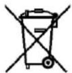
For EU countries only
Do not dispose of electric tools together with household waste material! In accordance with the European directive 2002/96/EC on waste electrical and electronic equipment and transposition into national law, obsolete electrical tools must be collected separately and recycled in an environmentally-compatible manner.

To reduce the risk of injury, please read the operating instructions.

Use hearing and eye protection
The machine and identification signs on the front and rear side according to figures 1 and 4 (Page 3).
2.3 Technical data
Erika 70:
| Universal motor, radio and TV interference suppressed | 230 V~, 50 Hz | |
| Power input (nominal load) | 2250 W | |
| Current at nominal load | 11,1 A - EU; 9,5 A - CH | |
| Saw blade speed during idling | 2050 - 4300 min-1 | |
| Saw blade speed at normal load | 2050 - 4300 min-1 | |
| Cutting depth 0°/30°/45° | 72/62/50 mm (2 53/64 / 2 7/16 / 2 in.) | |
| Tilting saw unit | -3° - 48° | |
| Saw blade diameter max/min | 225/210 mm (8 7/8 / 8 1/4 in.) | |
| Saw blade body thickness | 1,8 mm (1/16 in.) | |
| Tool cutting width | 2,5 mm (3/32 in.) | |
| Saw blade mounting hole | 30 mm | |
| Diameter extraction connection | 58 mm (2 9/32 in.) | |
| Weight | 37,2 kg (82 lbs) | |
| Dimensions: | ||
| Size of the tabletop | 818 x 525 mm (32 3/16 x 20 5/8 in.) | |
| Height of the tabletop | Feet folded | 413 mm (16 1/4 in.) |
| Feet unfolded | 891 mm (35 1/16 in.) | |
| Erika 85: | ||
| Universal motor, radio and TV interference suppressed | 230 V~, 50 Hz | |
| Power input (nominal load) | 2500 W | |
| Current at nominal load | 12,6 A - EU; 9,5 A - CH | |
| Saw blade speed during idling | 2050 - 4300 rpm | |
| Saw blade speed at normal load | 2050 - 4300 rpm | |
| Cutting depth 0°/30°/45° | 85/74/60 mm (3 3/8 / 2 29/32 / 2 3/8 in.) | |
| Tilting saw unit | -3° - 48° | |
| Saw blade diameter max/min | 250/240 mm (9 27/32 / 9 7/16 in.) | |
| Saw blade body thickness | 1.8 mm (1/16 in.) | |
| Tool cutting width | 2,8 mm (7/64 in.) | |
| Saw blade mounting hole | 30 mm | |
| Diameter extraction connection | 58 mm (2 9/32 in.) | |
| Weight | 40,0 kg (88.2 lbs) | |
| Dimensions: | ||
| Size of the tabletop | 915 x 525 mm (36 x 20 5/8 in.) | |
| Height of the tabletop | Feet folded | 413 mm (16 1⁄4 in.) |
| Feet unfolded | 891 mm (35 1/16 in.) | |
2.4 Emissions
The values stated are emission levels. Although there is a correlation between emission and imission level, it cannot be reliably derived from this whether additional precautions are necessary. Factors influencing the current immission level existing at the workplace comprise the duration of exposure, the room characteristic,
other sources of noise, etc. such as e.g. the number of machines and other adjacent machining operations. In addition, the permissible immission level may differ from country to country. This information is nevertheless suitable for providing the machine user with an improved assessment of the hazard and risk.
2.4.1 Noise emission specifications
Noise emission values determined according to EN 62841:
| Erika 70 | Erika 85 | |
| Sound pressure level | LPA=82.8 dB (A) | LPA=91.1 dB (A) |
| Uncertainty | KPA=1.0 dB (A) | KPA=1.0 dB (A) |
| Sound power level | LWA=101.4 dB (A) | LWA=105.7 dB (A) |
| Uncertainty | KWA=1.0 dB (A) | KWA=1.0 dB (A) |
The noise measurement was recorded using the saw blade included in the standard equipment.
2.5 Scope of supply
Pull-push saw Erika 70 complete with:
1 carbide-tipped circular saw blade 225mm (7 9/32 in.), 32 teeth
1 riving knife/splitter (thickness 2.2 mm (0.08 in.))
1 saw guard with extraction connection
1 universal stop
1 clamping piece
1 pushing stick
1 extraction hose
1 branch pipe (connection of upper and lower extraction connection)
1 service tool in bracket on the machine
1 operating manual
1 folder "Safety instructions"
Pull-Push Saw Erika 85 complete with:
1 carbide-tipped circular saw blade 250mm (7 9/32 in.), 40 teeth
1 riving knife/splitter (thickness 2.2mm 0.08 in.)
1 saw guard with extraction connection
1 multi-function stop
1 clamping piece
1 pushing stick
1 extraction hose
1 branch pipe (connection of upper and lower extraction connection)
1 service tool in bracket on the machine
1 operating manual
1 folder "Safety instructions"
2.6 Safety devices

Danger
These devices are required for the machine's safe operation and may not be removed or rendered inoperative.
The machine is equipped with the following safety devices:
- Upper saw guard
- Lower saw guard
- Splitting wedge
- Saw blade (after EN 847-1)
- Appropriate saw blade flanges
- Slowing time less than 10 s
- Stop system for safe guiding of workpiece
- Extraction connection
- Electrical safety corresponds to EN 62841-1
2.7 Use according to intended purpose
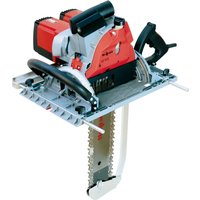
The pull-push saw Erika is only suitable as a circular saw bench and push-pull litre saw for longitudinal and cross cutting of solid wood.
Panel materials, such as chip boards, coreboards and Mdf boards as well and aluminium profiles and hard plastics may also be worked on. Use approved saw blades according to EN 847-1.
Any other use than described above is not permissible. The manufacturer cannot be held liable for any damage arising from such other use.
In order to use the machine as intended, comply with the operating, maintenance, and repair instructions specified by Mafell.
2.8 Residual risks

Danger
Even if used in accordance with its intended purpose and despite conforming with the safety instructions, residual risks caused by the intended use will always remain.
- Touching the moving saw blade within the cutting range.
- Cuts caused by the sharp saw blade teeth while exchanging the saw blade.
- Backlash of the workpiece or of workpiece parts.
- Hurling away of individual teeth of the saw blade.
- Touching live parts when the electrical installation spaces are opened and the machine has not been disconnected from the mains.
- Hearing can be impaired when working for long periods without ear protectors.
- Allergies, mucous membrane irritations by wood dust or lubricants.
3 Safety instructions

Danger
Always observe the following safety instructions and the safety regulations applicable in the respective country of use!
3.1 Protective cover-related safety instructions
- Leave protective covers fitted. Protective covers must be in working order and correctly fitted. Loose, damaged or malfunctioning protective covers must be repaired or replaced.
- Always use the saw blade protective cover and the riving knife/splitter for cross cuts. For cross cuts where the saw blade cuts completely through the thickness of the workpiece, the protective cover and other safety devices reduce the risk of injury.
- After completion of operations (e.g. sealing, grooving or splitting using the reversal process) which require removal of the protective cover and/or riving knife/splitter, immediately reattach the protective system. The protective cover and the riving knife/splitter reduce the risk of injuries.
-
Before switching on the power tool, make sure that the saw blade does not touch the protective cover, the riving knife/splitter or the workpiece. Accidental contact of these components with the saw blade can lead to a dangerous situation.
-
Adjust the riving knife/splitter according to the description in this operating manual. Wrong distances, position and alignment can be the reason why the riving knife/splitter does not effectively prevent a backlash.
- For the riving knife/splitter to function, it must act on the workpiece. If cuts are too short, the riving knife/splitter cannot prevent a backlash. In the case of cuts in workpieces which are too short to allow the riving knife/splitter to engage, the riving knife/splitter is ineffective. Under these conditions, the riving knife/splitter cannot prevent a backlash.
- Use the saw blade matching the riving knife/splitter. For the riving knife/splitter to work properly, the saw blade diameter must match the corresponding riving knife/splitter, the saw blade base body must be thinner than the riving knife/splitter and the tooth width must exceed the width of the riving knife/splitter.
3.2 Safety instructions for sawing methods
- DANGER: Do not place your fingers or hands near the saw blade or in the saw area. A moment of carelessness or slipping could direct your hand towards the saw blade and cause serious injury.
- Only feed the workpiece to the saw blade against the direction of rotation. Feeding the workpiece in the same direction as the direction of rotation of the saw blade above the bench may cause the workpiece and your hand to be pulled into the saw blade.
- Never use the litre stop to feed the workpiece when executing longitudinal cuts, and never additionally use the parallel stop for length adjustment when executing cross cuts with the litre stop. Simultaneously guiding the workpiece with the parallel stop and the litre stop increases the probability of the saw blade jamming and a backlash occurring.
- For longitudinal cuts, always exert the feed force on the workpiece between the stop rail and the saw blade. Use a pushing stick if the distance between stop rail and saw blade is less than 150mm , and a pushing block if the
distance is less than 50~mm . This type of working aid ensures that your hand remains at a safe distance from the saw blade.
- Only use the pushing stick supplied by the manufacturer or one that has been manufactured according to the instructions. The pushing stick ensures that there is sufficient distance between hand and saw blade.
- Never use a damaged pushing stick or one that has been saw into. A damaged pushing stick can break and cause your hand to be caught in the saw blade.
- Do not work "hands only". Always use the parallel stop or the metre stop to position and guide the workpiece. "Hands only" means that the workpiece is supported or guided with the hands instead of with a parallel stop or metre stop. "Hands only" sawing leads to misalignment, jamming and backlash.
- Never reach around or over a rotating saw blade. Reaching for a workpiece can lead to unintentional contact with the rotating saw blade.
- Support long and/or wide workpieces behind and/or at the side of the saw bench so that they remain horizontal. Long and/or wide workpieces tend to tip over at the edge of the saw bench; this leads to loss of control, jamming of the saw blade and backlash.
- Feed the workpiece evenly. Do not bend or twist the workpiece. If the saw blade becomes jammed, immediately turn off the power tool, unplug the power cord and correct the cause of jamming. Jamming of the saw blade by the workpiece may result in backlash or blockage of the motor.
- Do not remove cut material while the saw is running. Sawed material can get stuck between the saw blade and the stop rail or in the protective cover and pull your fingers into the saw blade when you try to remove it. Switch off the saw and wait until the saw blade comes to a standstill before removing the material.
- For longitudinal cuts on workpieces thinner than 2mm , use an additional parallel stop that is in contact with the bench surface. Thin
workpieces can get wedged under the parallel stop and lead to backlash.
3.3 Backlash - Reasons and corresponding safety instructions
A backlash is the sudden reaction of the workpiece as a result of a hooked, clamping saw blade or an oblique cut into the workpiece with respect to the saw blade. It can also occur if a part of the workpiece is jammed between the saw blade and the parallel stop or another stationary object.
In most cases, in the event of a backlash, the workpiece is caught by the rear part of the saw blade, lifted off the saw bench and hurled in the direction of the operator.
A backlash is the result of a wrong or incorrect use of the circular saw bench. It can be prevented by taking suitable precautions, as described below.
- Never stand in a direct line with the saw blade. Always hold on to the side of the saw blade on which the stop rail is located. In the event of a backlash, the workpiece can be hurled at high speed onto persons standing in front of and in line with the saw blade.
- Never reach over or behind the saw blade to pull or support the workpiece. Accidental contact with the saw blade may occur, or a backlash may cause your fingers to be pulled into the saw blade.
- Never hold and press the workpiece that is to be cut off against the rotating saw blade. Pressing the workpiece that is to be cut off against the saw blade leads to jamming and backlash.
- Align the stop rail parallel to the saw blade. A non-aligned stop rail presses the workpiece against the saw blade and creates a backlash.
- For concealed saw cuts (e.g. seaming, grooving or splitting using the reversal process), use a feather board to guide the workpiece against the bench and stop rail. With a feather board, you can better control the workpiece in the event of a backlash.
- Be particularly careful when sawing in nonvisible areas of assembled workpieces. The
plunging saw blade can cut into objects that can cause a backlash.
Support large boards to reduce the risk of backlash caused by a jammed saw blade. Large boards can bend under their own weight. Boards must be supported wherever they project beyond the bench surface.
- Be particularly careful when sawing workpieces that are twisted, knotted, warped, or do not have a straight edge along which they can be guided with a litre stop or along a stop rail. A twisted, knotted or warped workpiece is unstable and leads to misalignment of the saw kerf with the saw blade, jamming and backlash.
- Never saw several workpieces stacked on top of each other or behind each other. The saw blade could seize one or more parts and cause a backlash.
- If you would like to restart a saw, the blade of which is stuck in the workpiece, centre the saw blade in the saw kerf so that the saw teeth are not stuck in the workpiece. If the saw blade gets stuck, it can lift the workpiece or cause a backlash when the saw is restarted.
- Keep saw blades clean, sharp and adequately set. Never use warped saw blades or saw blades with cracked or broken teeth. Sharp and correctly set saw blades minimise jamming, blocking and backlash.
3.4 Safety instructions for the operation of circular saw benches
- Turn off the circular saw and disconnect it from the power supply before removing the bench insert, changing the saw blade, adjusting the riving knife/splitter or the protective cover of the saw blade, and when leaving the machine unattended. Precautions aim to prevent accidents.
- Never let the circular saw bench run unattended. Switch off the power tool and do not leave it until it has come to a complete stop. A saw running unattended poses an uncontrolled hazard.
- Children and adolescents must not operate this machine. This rule does not apply to young
persons receiving training and being supervised by an expert.
- Make sure that no other persons, in particular children, are present in the work area.
- Set up the circular saw bench in a place that is level and well lit, where you can stand safely and keep your balance. The place of installation must offer enough space to comfortably handle the size of your workpieces. Disorder, unlit working areas and uneven, slippery floors can lead to accidents.
- Consider environmental influences. Do not expose the machine to rain and avoid working in a damp or wet environment as well as near combustible liquids or gases.
- Regularly remove wood shavings and sawdust under the saw bench, from the dust extraction and/or the guides of moving parts. Accumulated sawdust is combustible and can self-ignite.
- Secure the circular saw bench. An improperly secured circular saw bench can move or tip over.
- Remove any adjusting tools, wood remnants, etc. from the circular saw bench before switching it on. Deflection or possible jamming can be dangerous.
- Always use correctly sized saw blades with matching mounting hole (e.g. diamond-shaped or round). Saw blades that do not match the mounting parts of the saw will run out-of-centre and lead to a loss of control.
- Never use damaged or incorrect saw blade mounting materials such as flanges, washers, bolts or nuts. This saw blade mounting material has been specially designed for your saw to ensure safe operation and optimum performance.
- Never stand on the circular saw bench and do not use the circular saw bench as a step stool. Serious injury may occur if the power tool tips over or if you accidentally come into contact with the saw blade.
- Make sure that the saw blade is mounted in the correct direction of rotation. Do not use any grinding wheels or wire brushes with the
circular saw bench. Improper installation of the saw blade or the use of unrecommended accessories may result in serious injury.
- Do not use any saw blades made of high-alloy high-speed steel (HSS saw blades).
- Do not make any changes to the machine that could compromise safety.
- Only use rubber-insulated extension cords (e.g. HO7 RN-F) with a cross section of at least 1.5mm^2 when working outdoors and make sure that the cord is not pulled over sharp edges.
- Install and lead the electrical connection cord away from the machine in such a way that there is no danger of stumbling at the operator station.
- Cutting of round timber is not permitted with the standard stops and feed aids.
- Examine the workpiece for foreign objects. Do not saw into metal parts, e.g. nails, since this could damage the sensitive carbide blades.
- Only begin cutting the workpiece when the saw blade has achieved its full speed.
- The wood dust generated during cutting impairs the necessary visibility and is partly harmful to health. The machine must therefore be connected to a sawdust extractor, e.g. a portable small extractor, if the work is not carried out outdoors or in a sufficiently ventilated room. At the same time, the provided extraction hose 5 (Fig. 5 - page 3) must be used as connection of the upper saw guard and the extraction connection 4. The air velocity must be at least 20m / s (65.6 ft/sec.).
3.5 Instructions on the use of personal protective equipment:
- Always wear closely fitting work clothes and take off rings, wristbands, and watches.
- The noise pressure level at the ear generally exceeds 85 dB(A). Operators should therefore wear ear protectors.
- In order to prevent eye injuries always wear an eye protection (safety goggles) or face protection when working with the machine.
3.6 Instructions on service and maintenance
- Before beginning maintenance and repair work, pull the connecting cable out of the socket outlet.
- Only allow an electrician to carry out work on the electrical parts of the machine.
- Damaged cables or plugs must be immediately replaced. Replacement may only be carried out by Mafell or an authorised MAFELL service workshop in order to avoid safety hazards.
- The MAFELL customer service must replace the tabletop, if the table slit has been sawed exceedingly.
- Only original MAFELL spare parts and accessories may be used. Otherwise, the manufacturer will not accept any warranty claims and cannot be held liable.
4 Setting / Adjustment
4.1 Installation / Transport
The machine is delivered in a transportation box. Check the machine for possible transport damages. Damage to the packing material may already be indicative of improper transport. Immediately notify your machine dealer of transport damages.
The following parts are packed loosely and must be installed or attached to the machine before start-up:
- Upper saw guard
- Extraction hose
- Branch pipe (connection of upper and lower extraction connection)
- Universal stop
- Pushing stick
- Clamping piece
Proceed as follows for assembly:

www.mafell.de/erika
- Upper saw guard
Unscrew the wing bolt 2 (Fig. 2 - page 3) counter clockwise up to the stop. Press
this wing bolt and push the saw guard 1 horizontally onto the riving knife/splitter 3. Make sure that the guide piece of the wing bolt is firmly engaged in the drilling of the riving knife/splitter when you release the wing bolt. Retighten the wing bolt 2.
The drilling at the rear left of the longitudinal side of the machine into which the saw guard can be hooked with or without the riving knife/splitter is intended for short-term storage of the upper saw guard with the riving knife/splitter removed (e.g. for plunge cuts). For transport purposes, the upper saw guard can also be attached to the mounting plate 50 (Fig. 5 - page 3) of the left rear foot.
- Extraction hose and branch pipe
First of all, attach the branch pipe 4 (Fig. 5 - page 3) to the extraction connection on the chip duct. Connect the extraction connection on the upper saw guard to the extraction hose 5. Push this hose onto the appropriate connection of the branch pipe.
Universal stop
The installation of the universal stop is described in chapter 5.10.
- Pushing stick / pushing handle
You can store the supplied pushing stick 6 (Fig. 5 - page 3) on the left longitudinal side of the machine in the bracket 42 provided for this purpose (Fig. 5 - page 3) and on the cast-on lateral transport handle 7.
For storing the pushing handle (special accessory), use the drilling on the front right on the longitudinal side of the machine, in which you can insert the pushing handle. According to your requirements, you can attach a pushing stick to the pushing handle. For this purpose, place the handle onto the pushing stick and press both tips into the timber. Then press on the wing bolt and screw it in.
- Clamping piece, cpl.
The clamping piece (of the universal stop) can be fastened on the bracket 43 intended for this purpose (Fig. 5 - page 3) with the wing bolt.
The cast-on transport handles 7 on both longitudinal sides can be used by two persons to transport the machine.
The vertically offset arrangement of the handles on the longitudinal and transverse sides enables easy transport of the machine over stairs, whereby the saw can be held by one person from above and by the second person from the bottom and therefore transported horizontally.
The two feet 9 and 10 (Fig. 6 - page 3) of the underframe can be folded for ease of transport.
For stationary operation of the machine, fold down both feet 9 and 10 until they engage in their final position. The adjustable foot can compensate unevenness of the underground. Fold the feet for transport, in particular to building sites. Proceed as follows:
- Push the rear blocking rod 8 (Fig. 3 - page 3) downwards to release the blocking and completely fold in the rear frame foot 9 (see Fig. 6) until the blocking rod engages.
- On the machine that is now standing in an inclined position, push the front blocking rod downwards and also fold in the frame foot 10 (Fig. 6 - page 3) until the blocking rod engages.
4.2 Mains connection
Prior to commissioning make sure that the mains voltage complies with the operating voltage stated on the machine's rating plate.
4.3 Upper saw guard
The upper saw guard is designed in accordance with legal requirements. The saw guard and side covers are designed to prevent unintentional contact between the user and the saw blade sprocket area. So as to ensure this, the side covers always rest on the table top or the workpiece and automatically adapt to the thickness of the workpiece. However, in the case of unfavourable angles and/or workpiece thicknesses, automatic opening is physically not possible. The workpiece or the stop system then
presses the side cover in the direction of the saw blade. Please observe the following instructions to prevent this:
- Always adapt the cutting depth to the workpiece thickness, see section 5.6.
- If necessary, set a sufficient distance between the stop and the saw blade or, in the case of the multifunction stop, retract the stop that is not required to allow the side covers to slide freely.
- For acute-angled sections, select the working direction so that the side covers meet the workpiece edge as perpendicular as possible.
4.4 Chip extraction
Connect the machine to a suitable external dust extractor during all work generating a considerable amount of dust. The air velocity must be at least 20 m/s (65.6 ft/sec.).
The inner diameter of the extraction connection is 58 mm (2 9/32 in.).
If you use the machine outdoors or in sufficiently ventilated rooms you can also use the chip collection system (Cleanbox) in the case of short operation. Do not forget that this must be exchanged at the latest when it is 80% full (with oak and beech wood dust ensure a dust free disposal!).
4.5 Saw blade selection
Use a sharp tool to obtain a good cut quality and select a tool from the following list according to material and application:
Cutting of solid wood crosswise and lengthwise to the grain direction and cutting of uncoated chip boards, plywood and the like:
- Erika 70: TCT circular saw blade 225× 2.5× 30 mm, 32 alternate top bevel teeth (item number see chapter 8)
- Erika 85: TCT circular saw blade 250× 2.8× 30 mm, 40 alternate top bevel teeth (item number see chapter 8)
Cutting of coated boards:
-
Erika 70: TCT circular saw blade 225× 2.5× 30 mm, 48 alternate top bevel teeth (item number see chapter 8)
-
Erika 85: TCT circular saw blade 250 × 2.8 × 30 mm, 60 alternate top bevel teeth (item number see chapter 8)
Cutting of aluminium profiles:
- Erika 70: TCT circular saw blade 225 × 2.5 × 30 mm, 68 alternate top bevel teeth (item number see chapter 8)
- Erika 85: TCT circular saw blade 250 × 2.8 × 30 mm, 68 alternate top bevel teeth (item number see chapter 8)
4.6 Saw blade change

Danger
Pull the power plug during all service work.

www.mafell.de/erika
- Bring the saw unit in central position (circular saw bench function) (see chapter 4.8).
- Adjust the saw blade to a cutting depth of about 45 - 70mm (Erika 85: approx. 45 - 85mm ) (see chapter 5.6).
- Remove the riving knife/splitter with the upper saw guard by pressing push button 41 (Fig. 10 - page 4) and simultaneously pulling the riving knife/splitter 3 (Fig. 2 - page 3) upwards and forwards.
- Tilt the machine to the side somewhat, so that the left longitudinal side is well accessible.
- Remove the hexagon head socket wrench 32 (Fig. 10 - page 4) from its bracket 33 on the lower saw guard cover.
- Open the locking mechanism 45 on the left side of the saw guard cover by turning it 14 turn to the left with the hexagon head socket wrench 32.
- Open the two lateral sliders (red) 40 on the saw guard cover by pushing them upwards until they engage.
-
Open the saw guard cover by 90^ and pull it forward approx. 30mm until the saw guard swivels downwards via the swivel rod.
-
Press the locking button 31 (Fig. 10 - page 4) in front of the lower saw guard and hold it tight. Using the hexagon head socket wrench 32, open the hexagon socket head cap screw 34 by turning it clockwise.
- Take off the front saw blade flange 35 and remove the saw blade to the top or bottom.
- Insert the new saw blade (observe the cutting direction, see the direction of rotation symbol in the cover).
- Insert the flange 35 onto the two flats and tighten the hexagon socket head cap screw 34 by turning it counter clockwise with the hexagon head socket wrench.
- Check whether the saw blade runs smoothly when turning by hand.
- Pull off the hexagon head socket wrench 32.
- Close the saw guard cover.
- Close the two lateral sliders item 40 (Fig. 10 - page 4) on the saw guard cover by pushing them downwards until they clamp / engage.
- Close the locking mechanism 45 on the left side of the saw guard cover by turning it 14 turn to the right with the hexagon head socket wrench 32.
- Push the hexagon head socket wrench 32 into the bracket.
- Push the riving knife/splitter together with the upper saw guard into the riving knife/splitter holding fixture until it locks into the riving knife/splitter holding fixture.
- If required, adjust the riving knife/splitter correctly (see chapter 4.6).
4.7 Riving knife/splitter

Danger
Pull the power plug during all service work.

www.mafell.de/erika
The kerf guide prevents during longitudinal cutting that the kerf closes behind the saw blade, resulting in a backlash of the workpiece.
This function is however only guaranteed, if the kerf guide is correctly adjusted, i.e., its distance to the tooth rim of the saw blade is max. 5 mm (3/16 in.) throughout the entire cutting depth (see Fig. 7) and its thickness is in between the kerf width and the blade thickness of the used saw blade. The provided kerf guide fits to the carbide tipped saw blades specified in Section 4.4.
Proceed as follows, if it is necessary to adjust the riving knife/splitter:
- Set the saw blade to the maximum cutting depth (see chapter 5.6).
- Remove the upper saw guard (see chapter 4.1).
- Bring the saw unit in central position (circular saw bench function) (see chapter 4.8).
- Set the saw unit to 45 inclined (see chapter 5.8).
- Open the locking mechanism 45 (Fig. 10 - page 4) on the left side of the saw guard cover by turning it 14 turn to the left with the hexagon head socket wrench 32.
- Push the two red lateral sliders 40 on the lower saw guard upwards until they engage.
- Fold the saw guard cover forward by approx. 90^ and pull the cover forward so that it swivels down via the swivel rod.
- Unscrew the hexagon socket head cap screw 37 (Fig. 7 - page 4) and adjust the riving knife/splitter 3 according to Fig. 7 with regard to its distance to the tooth rim and its height.
- Tighten the hexagon socket head cap screw 37.
- Close the saw guard cover again by swinging it forward and upwards through 90^ , push it back approx. 30 mm and close it by an upwards motion. Lock the saw guard cover in closed position by pushing down the two lateral sliders 40 (Fig. 10 - page 4).
- Close the locking mechanism 45 on the left side of the saw guard cover by turning it 14 turn to the right with the hexagon head socket wrench 32.
- Push the upper saw guard onto the riving knife/splitter again and tighten it in the required position (see chapter 4.1).
The kerf guide can be engaged in two positions without requiring tools:
- upper position with saw guard - for normal cuts
- lower position without saw guard - for covered cuts
In order to attain the respective position just pull the kerf guide upwards and forward or press it down and to the rear.
The riving knife/splitter can be removed without the use of tools (for plunge cuts and saw blade changes).
- Bring the saw unit in central position (circular saw bench function) (see chapter 4.8).
- Set the full cutting height.
- Remove the upper saw guard (see chapter 4.1).
- Press the push button in the slot-shaped opening in the upper, rear part of the lower saw guard.
- As long as you keep the push button pressed, pull the riving knife/splitter forwards / upwards according to the saw blade diameter.
When inserting the riving knife/splitter, make sure that the riving knife/splitter is pushed backwards and downwards at a distance of approx. 5mm from the saw blade diameter and that it is inserted into the groove of the riving knife/splitter bracket. Press the riving knife/splitter down to the stop or until it engages clearly (the push button need not be pressed during this process).
4.8 Application as pull-push saw
The special advantage when using as a push-pull saw is the trouble-free and precise separation of firmly attached workpieces up to max. 330mm - 13 in. (Erika 85:423 mm - 16-65 in.) cutting length on workpieces with a thickness of 16 mm (5/8 in.), e.g. panels. Apply the workpiece against the stop plate rail 14 (Fig. 9 - page 4) of the universal stop 15. Press the red release knob 16 and pull the saw unit forward with the handwheel 17 and pull rod 18. After completing the cutting procedure the saw unit runs back to the home position and is stopped there automatically.
4.9 Application as circular saw bench
Slitting of larger workpieces is carried out with the circular saw bench function. For this purpose, position the sawing unit in the foreseen table position. To do
so, turn the locking button 24 (Fig. 8 - page 4) clockwise and pull the saw unit that far forward that it automatically engages in the position provided for that purpose.
Use the universal stop 15 as parallel stop. You can thereby use the stop plate rail 14 according to the workpiece dimensions with the high workpiece bearing surface or turned by 90^ with its low bearing surface 25.
Return to the push-pull saw function by turning the locking button 24 counterclockwise. The saw unit then runs to the end position automatically.
4.10 Cleaning the filter
Slightly open the fillister head screw 44 (Fig. 11 - page 4). Disengage the filter housing 46 from the intermediate housing pivot point by moving it forward. Clean the filter housing. After cleaning, insert the filter housing in reverse order back into the intermediate housing 48 at the pivot points 47 (make sure that it engages into the pivot points on both sides). Fasten the filter housing by tightening the fillister head screw 44.
Alternatively, the fillister head screw 44 can be opened until the filter housing can be swivelled downwards by 90^ . Clean the filter housing with a tool suitable for this purpose. After cleaning, swivel the filter housing 90^ upwards and fasten it by tightening the fillister head screw 44.
5 Operation
5.1 Initial operation
Personnel entrusted to work with the machine must be made aware of the operating instructions, calling particular attention to the chapter "Safety instructions".
5.2 Switching on and off
- Switching on: Press the green switch button 12 (Fig. 9 - page 4).
- Switching off: Press the red switch button 11. The saw shaft is automatically braked, reducing the slowing down time to less than 10~s .

For transport you can wind the connecting cable over the brackets 13 on the right side of the machine (at the same time transport handles).
5.3 Light

Danger
Pull the power plug during all service work.
The power tool is equipped with a light module 49 (Fig. 2 - page 4) in the upper saw guard
The light module is supplied with power for a certain period of time as soon as the machine is switched on, and is then ready for operation.
When it is ready for operation, the light module automatically switches the light on when the machine is moved or switches it off when the machine is standing still for longer periods.
For a trouble-free function of the light, the golden contact surfaces on the riving knife/splitter must be cleaned if they become dirty. To do this, remove the riving knife/splitter and clean the contact surfaces of dust and chips with a cloth.
5.4 Speed selection
In order to achieve perfect cutting quality according to worked material, the saw blade speed can be stepplessly selected between 2050 - 4300 rpm. Select the speed with the setting wheel arranged below the main switch.
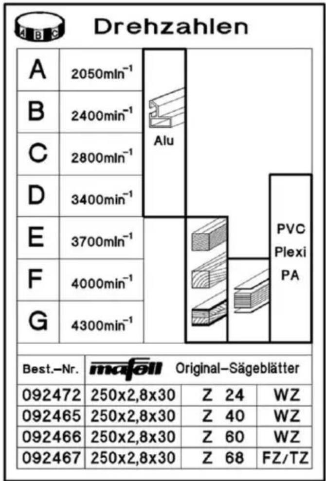
Please note that ideal cutting quality not only depends on the speed but also on the saw blade and saw blade sharpness. For information on suitable saw blades, see chapter 4.4.
5.5 Overload protection
Triggering of the motor protection is always a sign for motor overload, whereby the cause must be determined and eliminated.
The speed is automatically reduced when the motor is overloaded respectively the motor is automatically shut down in the case of power failure. You can turn the motor on again after the power supply has been resumed.
5.6 Cutting depth adjustment
The cutting depth can be continuously adjusted from 0 to 72mm (0 to 2 3/4 in.) - Erika 85:0 to 85mm (0 to 3 11/32 in.) by turning the handwheel 17 (Fig. 8 - page 4). Turning clockwise increases the cutting
depth; turning anticlockwise decreases the cutting depth.
In order to achieve good cutting quality, the adjusted cutting depth of the saw blade should be approx. 5 mm (3/16 in.) more than the processed material thickness.
Depending on the riving knife/splitter position in the two latching positions, the measuring scale 38 (Fig. 7 - page 4) that is mounted on the riving knife/splitter and standing perpendicular to the table surface can be used as aid for setting a specific cutting depth. This however only applies to saw blades with 225 mm (8 7/8 in.) - Erika 85: 250 mm (9 27/32 in.).
If an accurate adjustment of the cutting depth is necessary, e.g. when grooving or chiselling always start from below in order to compensate possible play.
5.7 Plunge cuts

Danger
Risk of backlash during plunge cuts! Before the plunge cut, place the part against the front edge of a fixed stop, if possible. During the plunge cut, press the part firmly against the bench surface. As you press, pay attention to the danger zone caused by the emerging saw blade.

www.mafell.de/erika
Remove the upper saw guard, see chapter 4.1. Remove the riving knife/splitter, see chapter 4.5.
Turn the saw blade down with the hand wheel until it has disappeared under the bench top.
The plunge cut can be made at infinitely variable cutting depths (0 to 85mm ) by turning the hand wheel 17 (Fig. 8 - page 4) (Caution: the saw blade emerges from the workpiece in a slight arc towards the front). Turning clockwise increases the cutting depth; turning anticlockwise decreases the cutting depth.
After the plunge cut, fit the riving knife/splitter back in its original position, see chapter 4.6 and fit the saw guard back on the riving knife/splitter, see chapter 4.5.
5.8 Setting for bevel cuts

Danger
Make sure before inclining with a running saw blade that neither the multi-function stop nor workpieces are in the swivel range of the saw blade.
For angles up to 45^ , first release the locking lever 19 (Fig. 9 - page 4) by turning counterclockwise. Swivel the saw unit by turning the handle 20. The cutting angle is indicated on the angle scale 21 on indicator 22. Tighten the locking lever 19 again.
Actuating the turning knob 23 enables tilting the saw unit by 3^ over both end positions 0^ and 45^ . The turning knob returns automatically to the home position when swivelling back so that the 0^ - and/or 45^ position is precisely reached.
5.9 Multi-function stop (scope of delivery Erika 85)
Please infer the description from the enclosed assembly instructions and spare parts list.
5.10 Universal stop (scope of delivery Erika 70)
The complete universal stop consists of the retaining bracket 15 (Fig. 8 - page 4) and the adjustable stop plate rail 14 in the retaining bracket. You can clamp it firmly according to requirements to at all sides of the table in the dovetail guides using the wing bolts located on the underside of the rod holder 27.
This stop can be used both as parallel stop on the circular saw and also as cross and metre stop for the pull-push saw.
The position of the stop rail (workpiece unit) to the index plate and/or to the scale has been precisely adjusted in the factory. Nevertheless, if a later adjustment should become necessary, this is accomplished as follows:
- Attach the universal stop in the dovetail guide on the right or left longitudinal side of the table.
- Bring the stop rail into the 0^ position by releasing the upper wing screw 28 and tighten the wing screw.
- Loosen both cylinder-head screws, which are accessible from above with a screwdriver.
- Push the stop rail against the saw blade after loosening the lateral wing bolt on the rod fixture 27 until it rests against the saw blade.
- Retighten the cylinder-head screws.
The angle display remains on the scale after readjusting the stop!
5.11 Application as parallel stop
You can fasten the universal stop in different positions and use it as a parallel stop (see Fig. 8 - page 4):
- on the right or left front side of the bench when setting the stop rail 14 (Fig. 8 - page 4) to 0^ on the angle scale. When using it on the right-hand side, make sure to set a clear cut of the saw blade. For this purpose, fasten the stop in the dovetail guide in such a way that the stop rail runs from the front edge of the bench to beyond the centre of the saw blade. (Machine in circular saw bench function)
Adjust the cut width after unscrewing the lateral wing bolt on the rod holder 27 by shifting the guide rod. The width can be read off the scale 29 at the edge of the stop rail that is facing the saw blade. After adjusting, tighten the wing bolt again.
- Fasten the stop rail additionally at the front edge of the bench by means of the clamping piece. To do so, insert the square nut on the clamping piece into the groove of the stop rail. Unscrew the wing nut on the clamping piece until the wedge engages behind the dovetail profile of the bench top. Tighten the wing nut.
- on the right or left front side of the bench when setting the stop rail 14 to 90^ . At the same time, adjust the stop after unscrewing the lateral wing bolt on the rod holder 27 by moving the guide rod in such a way that the stop rail runs from the front edge of the bench to behind the riving knife/splitter. (Machine in circular saw bench function)
Adjust the cut width after unscrewing the wing bolt on the underside of the rod holder 27 by moving the entire stop in the dovetail guide. The cut width can be read off the scale 29 at the edge of the stop rail that is facing the saw blade. After adjusting, tighten the wing bolt again.
The stop of stop rail 14 can be adjusted in longitudinal direction. If there is a risk, e.g. when cutting solid wood longitudinally, of the workpiece jamming between stop and saw blade, then the stop rail is moved in such a way that its rear end reaches approximately up to the centre of the saw blade. To do so, release the clamping arm 30 (Fig. 8 - page 4) arranged on the top of the stop and move the stop rail. After adjusting, tighten the clamping lever again. The stop rail 14 can also be used turned by 90^ . This facilitates cutting of narrow workpieces in particular with an inclined saw blade, since the then available small bearing surface enables closer positioning of the parallel stop to the saw blade. For this purpose, release the clamping lever 30 at the stop. Pull the stop rail 14 completely out of the bracket. Insert the stop rail turned by 90^ in such a way that the narrow edge points to the saw blade. Then tighten the clamping lever again. When the stop rail is in this position, the cut width can also be read off the scale 29 at the edge facing the saw blade.
5.12 Application as cross stop and mitre stop

Danger
Only carry out adjustments on the universal stop when the saw blade is stationary.
The universal stop is best attached to the front left table side for cross and litre cuts in pull-push saw function. The 0^ mark is indicated on the angle scale in this position with right angled cuts.
For carrying out angular cuts, loosen the wing bolt 28 located on the upper side (Fig. 9 - page 4). Tilt the stop rail after the scale into the required position. A latching position is available every 15^ . Afterwards, tighten the wing screw.
The 15^ steps can be deactivated by means of the slider underneath-the angle scale. For this purpose press on the unilateral projecting part of the slider, whereby the stop may not be engaged.
The stop rail should always as close as possible to the cutting plane, in order to achieve better cutting quality. It is therefore released at its ends, so that the upper saw guard can be moved close enough when cutting narrow workpieces. To adjust the stop rail, loosen the clamping lever 30 (Fig. 8 - page 4).
Shifting the guide rod in the rod fixture 27 enables adjusting the stop in such a way that depending on the respective workpiece dimensions and optimal adjustment of the kerf width can be obtained.
6 Service and maintenance

Danger
Pull the power plug during all service work.
MAFELL machines are designed to be low in maintenance.
The ball bearings used are greased for life. When the machine has been in operation for a longer period of time, we recommend to hand the machine in at an authorised MAFELL customer service shop for inspection.
Only use our special grease, order No. 049040 (1 kg tin) for all greasing points.
6.1 Examination of the safety devices
The safety of the machine depends primarily on the functional capability of the provided safety devices. It is therefore important that these devices are examined regularly for correct condition. This comprises in particular the riving knife/splitter, the upper saw guard and the lower saw guard.
Furthermore, the following must be checked every two weeks:
- automatic return of the saw unit to the home position when used as a pull saw (see chapter 4.7)
- automatic locking of the saw unit in the home position after returning
- functional capability of the automatic locking of the saw unit in the centre position when used as a circular saw (see chapter 4.8)
- trouble-free movement of the saw guard wings from the max. cutting height to the bench top.
- mains cable for damage
6.2 Machine care
The sliding and rolling parts must be occasionally cleaned of chips and dust with a suitable vacuum cleaner. Occasional spraying with a commercially available lubricant (e.g. Caramba) facilitates sliding of the parts.
In order to avoid too large a temperature rise of the motor check occasionally that there is no dust deposit
7 Troubleshooting

Danger
Determining the causes for existing defects and eliminating these always requires increased attention and caution. Pull the mains plug beforehand!
Some of the most frequent defects and their causes are listed in the following chart. If case of other defects, please contact your dealer or the MAFELL customer service.
| Defect | Cause | Elimination |
| Machine cannot be switched on | No mains voltage | Check power supply |
| Mains fuse defective | Replace fuse | |
| Carbon brushes worn | Take the machine to a MAFELL customer service shop | |
| Machine switches off automatically during idling | Mains failure | Check mains-side back-up fuses The machine does not restart due to the installed undervoltage protection and must be turned on again after power has returned |
| Machine stops while cutting is in process | Mains failure | Check mains back-up fuses |
| Machine overloaded | Reduce feed speed | |
| Workpiece jams when feeding | Blunt saw blade | Hold workpiece and turn motor off immediately. Then exchange the saw blade |
| Stop rail of the universal and/or the multi-function stop is not parallel to the saw blade | Readjust the stop rail, see chapter 5.10 | |
| Burn marks on the cut surfaces | The saw blade used is unsuitable for the task or blunt | Replace saw blade |
on its surface. If dirty, the filter housing on the motor must be cleaned (see 4.9).
6.3 Storage
If the machine is not used for a longer period of time, it has to be carefully cleaned. Spray bright metal parts with a rust inhibitor.
| Defect | Cause | Elimination |
| Chip outlet blocked | Operation without extraction | Remove the chips after turning the machine off. To do so, open slider 39 (Fig. 10 - page 4). The chips in the chip duct can now be easily removed downwards. Then close the slider to the rear again. |
| Extraction too weak | Use an extraction unit, which guarantees an air speed of at least 20 m/s (65.6 ft/sec.) at the extraction connection piece | |
| Wood particles in the chip ejector | Open slider 39 (Fig. 10 - page 4). The wood particles can now be easily removed downwards out of the chip duct. If this should not be completely possible, lower the saw blade as far as possible. Then close the slider to the rear again. | |
| Height adjustment is sluggish | Pull rod, worm toothed segment and retaining plate dirty | Clean components and grease or lubricate |
| Pulling device is sluggish | Pull rod, ball bearing running surface and guide tube dirty | Clean components |
| Tubular frame cannot be folded in | Upper saw guard in parking position on tubular frame and saw unit swivelled to more than 30° | Swivel saw unit to less than 30° |
| Light goes off | Machine was not moved for approx. ten seconds | Light module has been automatically set to idle state and switches on again automatically when the machine is moving |
| The contact surfaces on the riving knife/splitter are dirty | Remove the riving knife/splitter and clean the golden contact surfaces of dust and chips with a cloth. |
8 Optional accessories
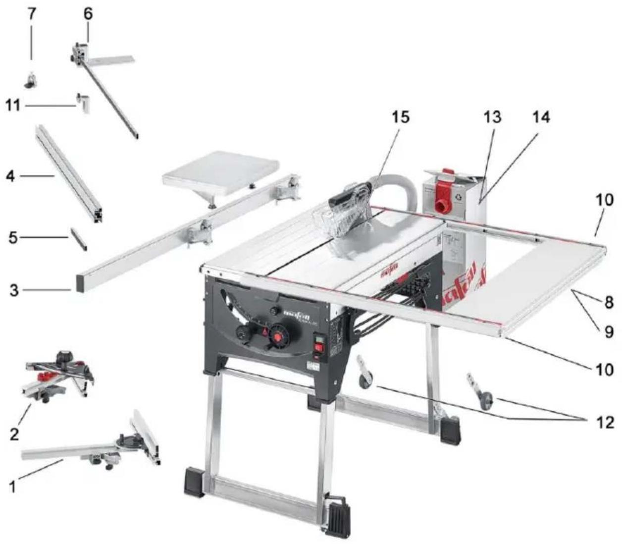
- (3) Sliding carriage, CPL. Order No. 038563
- (1) Universal stop, CPL. Order No. 201611
- (4) Stop ruler 1.000 mm incl. Trimming cover Order No. 203396
- (5) Connecting piece Order No. 038393
- (6) Telescopic rod, cpl. Order No. 038309
- (11) Trimming cover Order No. 038306
- (10) Mounting bar 1000 mm Order No. 038686
- (7) Clamping piece Order No. 038294
- (8) Supplementary bench for Erika 70 Order No. 208438
- (9) Supplementary bench for Erika 85 Order No. 208439
- (15) TCT saw blade 225 × 2.5 × 30 ~mm , 32 teeth / WZ (Erika 70) Order No. 092460
- (15) TCT saw blade 225 × 2.5 × 30 ~mm , 48 teeth / WZ (Erika 70) Order No. 092462
- (15) TCT saw blade 225× 2.5× 30mm , 68 teeth / FZ/TR (Erika 70) Order No. 092464
- (15) TCT saw blade 250× 2.8× 30mm , 24 teeth / WZ (Erika 85) Order No. 092472
- (15) TCT saw blade 250× 2.8× 30mm , 40 teeth / WZ (Erika 85) Order No. 092465
- (15) TCT saw blade 250 × 2.8 × 30 ~mm , 60 teeth / WZ (Erika 85) Order No. 092466
- (15) TCT saw blade 250 × 2.8 × 30 ~mm , 68 teeth / FZ/TR (Erika 85) Order No. 092467
- (12) Mounting kit wheels Order No. 202889
- (2) Multi-function stop Order No. 207980
- (13) Cleanbox starter packet Order No. 203402
- (14) Cleanbox, 5 pieces Order No. 203575
9 Exploded drawing and spare parts list
The corresponding information in respect of spare parts can be found on our homepage: www.mafell.com

www.mafell.de/erika
Sommaire
El carril de tope 14 se pueda girar 90^ . Con ello, seSEOSEOSEOSEOSEOSEOSEOSEOSEOSEOSEOSEOSEOSEOSEOSEOSEOSEOSEOSEOSEOSEOSEOSEOSEOSEOSEOSEOSEOSEOSEOSEOSEOSEOSEOSEOSEOSEOSEOSEOSEOSEOSEOSEOSEOSEOSEOSEOSEOSEOSEOSEOSEOSEOSEOSEOSEOSEOSEOSEOSEOSEOSEOSEOSEOSEOSEOSEOSEOSEOSEOSEOSEOSEOSEOSEOSEOSEOSEOSEOSEOSEOSEOSEOSEOSEOSEOSEOSEOSEOSEOSEOSEOSEOSEOSEOSEOSEOSEOSEO SEOEO SEOEO SEOEO SEOEO SEOEO SEOEO SEOEO SEOEO SEOEO SEOEO SEOEO SEOEO SEOEO SEOEO SEOEO SEOEO SEOEO SEOEO SEOEO SEOEO SEOEO SEOEO SEOEO SEOEO SEOEO SEOEO SEOEO SEOEO SEOEO SEOEO SEOEO SEOEO SEOEO SEOEO SEOEO SEOEO SEOEO SEOEO SEOEO SEOEO SEOEO SEOEO SEOEO SEOEO SEOEO SEOEO SEOEO SEOEO SEOEO SEOEO SEOEQ
4.10 Gora rent filter
Erika 70: apt. Ng 972001, 972020, 972021
Erika 85: apt. No 971901, 971920, 971921
2.1 CBeDeHnO npOn3BoDnteNe
DpeBeCHOCtpyKeHbIe PnITbI, CToJIaRpHbIe PnITbI n PnITbI MΦ, a TaKxE aIOMnHneBbIe npoФnI IN TBepDbIe PnactIKN, TaKxE MOxHO o6pa6aTbIBaTb. IcnoJb3yIte pa3peUeHHbIe NnIbHbIe DnCKn corNaCHO EN 847-1.
NcnoIb3OBaHHe He no Ha3HaueHnIO, ONncAHHomy Bblwe, 3anpeSeHo. Ppon3BOJnteJIb He Hecet OTBETCTBeHHOCTn 3a yUep6, BO3HnKlMn B pe3yIbTaTe TaKOrO dpyrOro NcNoIb3OBaHnIa.
4.10 OuInctKa 6nIbTpA
Clerka OTBnHTIe BnHT C nIOCKOBblnyKlOJ rOIOBko 44 (pnc.11-cTp.4).3aΦnKcnpyTe KOpNyc fInbTpa 46, cDnHyB Bnepei n3 ToQKn BpaueHnra nepexodHO KOpNyca. IocnCTNe KOpNyc fInbTpa. Iocne uCTkn yctAHOBtE KOpNyc fInbTpa Ha TOnKy BpaueHnra 47 B o6paTHo NocJeDOBaTeJBHoCTn CHOBA B nepeXoHDH KOpNyc 48 (CJeDHe 3a DByXCTOPOHHe FnkCaUeB ToQkax BpaueHnra). 3akpenTe KOpNyc fInbTpa 3atrNBaHHem BnHTa C nIOCKOBblnyKlOJ rOIOBko 44.
Kak BapnaHT MOXHO OTBnHTNTb BNHT C NIOCKOBblnyKlnoI rOJbKOi 44, noka KOpNyc fNlbTppa MOxHo 6ydt NOBepHyb Bn3 Ha 90^ . OChCTnte KOpNyc fNlbTppa NODxOJaUIM dIa 3TOrO NHCTpyMeHToM. Iocne YnCTkn NOBepHnTe KOpNyc fNlbTppa 90^ BBepx n 3aKePnTe erO 3aTgNBaHnem BNHTa C NIOCKOBblnyKlnoI rOJbKOi 44.
5 3Kcnpnyatazaia
5.1 BbO D B 3KcNpyatauH
DaHnyo HNCTpyKcIIO NO 3KcNpyatauIN CNe dyET DOBecTn Do CBeDeHNA BCEX NlU, KOToPbIM NOpyuHo UnpaBHeHne MaunHO, PnueM Oco6oe BnMaHne CNe dyET o6paNTb Ha pa3dJI „Ppabnna 6e3onacHOCTn".
5.2 BkIIOueHne N BBIKIOueHne
BkIIOueHne:HaXMMTe Ha 3eJIeHyIO KHOIky BbIKNIOyAteTn 12 (pnc.9-CTp.4).
BbIKJIOUeHne: HaxMITE KpaCHyO KNONKy BbIKJIIOuATEIa 11. Pn 3OM npoCxOaNT aBTOMaTNUeCKoe TOPMOXeHne BaIa NIIbI C cOKpaUeHEm BpeMeHb BBiBaRa Do MeHee 10c.

PnpcoeHnHTbHbI KaBb MOxHO HAMOTaTb Dnra TpaHCnOpTnPOBKn Ha npaByo CTOPOHy MaunHbI Chepe3 npedyCMOTpeHHbIe KpennHeHn 13 (ODHOBPemHo pyKn dJa TpaHCnOpTnPOBKn).
5.3 OcBeueHne

Onacho
PnpnpoBeHnIIO6bIXpa60ntnoTexHnueCKOMyO6cnyXnBaHHIOBbIHMaTb BnIKy COeINHHTeNbHOOnHypa.
3JIeKTPoHnCTpyMeHT OCHaUeH MOyIeM OCBeUeHn4 49 (pnc.2-ctp.4) B BePxHem 3aunTHOM KoxyXe.
Modylb ocbeuHnna dInTeIbHoe Bpem npn BKIOUeHHn INCTpyMeHa cHa6XaETcra ONpeDeIeHHoe Bpem, a 3aTEM rOTOB K pa6ote.
B coCTOHN 3KcNJIyatauHOHON roTOBHOCTM MOyNb OCBeUeHNA BtOMaTnueeCKN BKJIOUaET CBET npi nepemueHNN MaunHb INN CHOBA BbIKIIOUaET eO npi DInTeJBHom 6e3dEChBNI.
Дябспесьою pa60tbi CBeta OYNCHTte OT 3aRpy3HeHn 3OJToBle KOHTaKTHbIe NOBepxHOCTn Ha packJIINHBAIOUeM HOKe.ДЯ 3TOrO N3BLeKInTe packJIINHBAIOUH HOK N OYNCHTte TpIKNoI KOHTaKTHbIe NOBepxHOCTN OT nbIIN n CTpyKKn.
5.4 Bb6op ckopoctn BpaueHna
Дя obecneeynoNTMaIbHOrO KaueCTBa
pacnIOBKn B 3aBNCIMoCTn OT o6pa6aTbIbAemoro
MaTePnAna, CKOpocTb BpaUeHnI NIIbHOrO DnCKa
BeccTypeHato perynuPyetcB npedeJax 2050 -4300 MInH-1. Ee moKHO BblbupaTb yCTaHOBOyHbIM
KOJIecOM, pacNoJIOXeHHbIM NOd TJaABHbIM
BbIKIOUaTeJIeM.
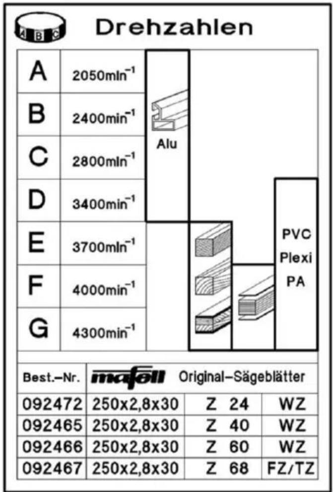
Pn 3OM CJeIyET yYeCTb, YTO ONTUMaJIbHOe KaueCTBO paCNIIOBKN 3aBNCIT He TOnbKO OT YaCTOTbl BpaSeHnA, aN OT NJIbHOrO DNCKa I erO OCTPOrbl. Yka3AHnO THOCHTeJIbHO NOxODJUeRO NIIbHOrO NoJIoTHa CM. B pa3dene 4.4.
5.5 3aunTa oT neperpy3KN
Cpa6aTbIBaHne 3aunTbI dBiratela NOCToHHO YBnEeTCr npn3HaKOM neperpy3Kn DBiratela, npnuHy KOtopoH Heo6xOIMO oPpeJeNTb H yctpaHntb.
Ipi neperpy3Ke DnraTeTcKOpocb BpaueHn ABTomatNueckn POnHxAeTc, PpO TKNIOUeHn 3JIeKtpo3Heprn PpONCXoNT ABTomatNueceKoe BbIKIOUeHne. IocNe BOCCTaHOBNEHn HAnPjaKeHn MOXHO CHOBa BKIOHTb MaUNHy.
5.6 HacrpoKa rnybHbI pe3a
InybHy npoHnMa MoXHo nlaBHO HAcTpOHTb NOBOPOTm MaxOBuYka 17 (pnc.8-cTp.4) ot 0 do 72 MM (Erika 85:0do 85 MM). NOBOPOTm no
Yacobov CTpeIke yBeHnUHbAeTcraIy6bHa npOnnla, UMeHbSaeTcra OHa IPOTNBOJIOJXHBIM BpaJeHneM. YTo6bl Do6ntbcx XopoWero KaueCTBa npOnnla, HAcTpoEHNa rIy6bHa npOnnla NIIbHoro DnCKa DOJxHa 6bITb npImepHo Ha 5 MM 60JIbSe TOnIuHbI O6pa6aTbIBaEMOro MaTePnAna.
B 3aBnCmOCTN OT NOLOXeHnPaCKINHnBaHOUeTo HOxBA O6oON X NIOLOXeHnX FHKCaUN MOKHO NcNoB3OBaTB YCTAHOBJIeHHyU Ha paCKInHnBaIOUeN HOK IN paCNOJIOXeHHyU BEPTNUKaJIbHO IO OTHOWeHHIO K NOBepxHOCTN CTOna I3MePntbHyU ShKaIy 38 (pnc.7-CTpaHnua4) KAK BCnOMOraTeNbHoe CpeDCTBO DnI NaHactpoiKn ONpeDeJIeHHo IITy6uHbI npOnnla. 3TO Kacaetc ToIbKO NIIbHOrO DNCKa C 225 MM (Erika 85:0250 MM).
Ecn Tpe6yETcTouHa HAcTPOKa rIy6nHbI npOnu, HanpImep IJn Na3OB nn PhaIbueB, yCTaHaBnBaIe ee Bcerda CHN3y, YTO6bl KOMNeHCnPoBaTb BO3MOxHbI JIOΦT.
5.7 Pa3pe3bI c yTaNIBaHHem

Onacho
Onachoctb otdaun npn
BblnoJIHeHn pa3pe3OB C
yTaNIBaHnEM! Npeed
yTaNIBaHnEM NOJoxNte DeTaJIb
NO BO3MOxHOCTn Ha nepeDnH
KpaI Ha 3aKpeNJIeHHom yNope.
PpIXMITE npu yTaNIBaHn
DeTaNb K NOBepXHOCTn CTola.
CneIte npn HaxImaHn 3a
ONaCHO 3OHONy TaNIBaEMORO
PiNbHOro NoJOTHa.

www.mafell.de/erika
CHIMITE BepxHn 3aunTHbI KoxyX, cm. pa3dE1 4.1.
H3BLeKInTe packNINHBAIOUcN HOK, cm. pa3dE1 4.5.
BpaaTe maxOBKOM nIbHoe noIoTHo Bn3, oKa OHO He Icye3HeT IOd IInToi CTOna.
Pa3pe3 c ytanINBaHnEM MOxHO BbINOHNITb PnABHBIM BpaueHnEM maxOBnka 17 (pnc.8-ctp.4) ot 0 do 85 MM (BHHMaHHe: NJIbHoE NOJTOHO BBIOHTcA n3 aROTOBKn CJIeRka N3OrHyTbIM Bnepe).
IobopoTOM no yacOBoCtpeKe yBeHnUHbAEcra rLy6nHa npOnnla, yMeHbAeTcra OHa npOTNBONIOJXhBIM BpaueHHeM.
Iocne pa3pe3a c yTaJIINBaHHeM yCTaHOBInTe packJIINHBAIOUH Hox CHOBa B NCXOJHOE MeCTO, CM. pa3dEn 4.6 mOHTnpyTe 3aUNTHbIK KOKyX CHOBa Ha packJIINHBAIOUH HOK, CM. pa3dEn 4.5.
5.8 HactpoKa dЯ haKNoHHbIx pa3pe3OB

Onacho
CneIte nepeHaayanom
HaKIOHHO NOIOKeHnpy
pa6oTAIOUeM NINbHOM N0IoTHe 3a
TEM, YTO6bI HN
MHOROyHKUHOHaJIbHbI yOp, HN
3aROTOBKn He HaxOuINcB
DInaNa3OHe NOBOPaUNBaHn
IIINbHOrO NoJOTHa.
Дя ула д 45° chayana OTBHTITE CTONOPнь pbyar 19 (pnc. 9 - ctp. 4), NOBepHyB npoTnB YacOBо CTpeKN. NOBepHnte pacnIOBOUHb arperat NOBOpOTm pykn 20. Ha yrnoBoi shkaJe 21 CTpeKoN 22 OTo6paKaetc yroI pe3a. Choba 3aФИКСИРУTe CTONOPHь pbyar 19.
KoHCTpyKzna Maunn MAFELL Tpe6yeT MInHMaJIbHOrTO TexHnueCKOrO 06cnyKuBaHnI.
IcnoJb3yemblie 7apNKoONdUHnHnKcMa3aHbHa Becb cpoK 3KcNlyaatau. NocJe dInTeJbHOJ 3KcNlyaatauMbI peKOMeHNyEM nepeDaTb MaunHy Ha TexHnueckn OCMOTp aBTOPn3OBaHHoHΦnpMOJ MAFELL MaCTepckO no 06cnyXnBaHHIO KJIeHTOB.
Дя Смади BCEX TOYEК Cмади ИСПОЛБ3уITE TOLБКO HAшу Спсцальню консгет entHyю Cмаду, № ДЯ Зakаэ 049040 (1 К 6анka).
4.5 Vyber pilovych kotouču
Erika 70: St. art. 972001, 972020, 972021
Erika 85: St. art. 971901, 971920, 971921