45222 - Continuity tester Wiha - Free user manual and instructions
Find the device manual for free 45222 Wiha in PDF.

| Product Type | Electrical Continuity Tester |
| Brand | Wiha |
| Model | 45222 |
| High Measurement Range | 0 … 500 kΩ |
| Low Measurement Range | 0 … 10 Ω |
| Tolerance | ±25 % (both ranges) |
| Test Current (High) | <5 μA |
| Test Current (Low) | <20 mA |
| Sound Indicator | Yes (buzzer) |
| LED Display | Rx, range, hazardous voltage, low battery |
| Overvoltage Protection | 400 V AC/DC for 30 s |
| Automatic Power-On | Yes, detection <500 kΩ |
| Flashlight Function | Yes, automatic shutoff after 30 s |
| Power Supply | 2 AAA batteries (1.5 V) |
| Low Battery Indication | Battery symbol LED |
| Self-Test | Possible by shorting the test leads |
| Safety | IEC/EN 61010-1, IEC/EN 61010-031, double insulation, CAT II 400 V |
| Intended Use | De-energized continuity testing only |
| Operating Temperature | 0 … 40 °C |
| Cleaning | Damp cloth with mild household cleaner |
| Battery Replacement | Open housing (screws), replace AAA batteries |
| Package Contents | Tester, 2 AAA batteries, user manual |
| Test Leads | Fixed with test probes |
| Warranty | According to manufacturer's conditions |
Frequently Asked Questions - 45222 Wiha
User questions about 45222 Wiha
0 question about this device. Answer the ones you know or ask your own.
Ask a new question about this device
Download the instructions for your Continuity tester in PDF format for free! Find your manual 45222 - Wiha and take your electronic device back in hand. On this page are published all the documents necessary for the use of your device. 45222 by Wiha.
USER MANUAL 45222 Wiha
natural_image
Icon of an open book inside a dark circle (no text or symbols)DE....3
EN....13
FR 23
NL....33
ES 43
IT....53
DA....63
NO 73
SV 83
FI....93
PL 103
CS....113
RU....123
HU....133
BEDIENUNGSANLEITUNG
Inhaltsverzeichnis
Website: www.wiha.com
Introduction / Scope of supply 14
Transport and storage 15
Safety....16
Appropriate usage 17
Control elements and connections 18
Using of device 18
Maintenance 19
Cleaning 19
Battery replacement 20
Technical data....21
Service and warranty....22
INSTRUCTION MANUAL
References marked on instrument or in instruction manual

Warning of a potential danger, follow with instruction manual.

Caution! Dangerous voltage. Danger of electrical shock.

Reference! Please use utmost attention.

Continuous double or reinforced insulation category II IEC 536.

Complies with EU specifications.

Complies with UK specifications.

Instrument fulfill the standard (2012/19/EU) WEEE.
Introduction / Scope of supply

The instruction manual contains information and references, necessary for safe operation and maintenance of the instrument. Prior to using the instrument (commissioning / assembly) the user is kindly requested to thoroughly read the instruction manual and comply with it in all sections.

Failure to read the instruction manual or to follow with the warnings and references contained herein can result in serious bodily injury or instrument damage. The respective accident prevention regulations established by the professional associations are to be strictly enforced at all times.
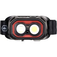
The continuity tester 45222 is appropriate for continuity testing of electronic wiring, line networks, systems, instruments and components of a measurement impedance of 500 kΩ. It has 2 ranges, up to 10 Ω and up to 500 kΩ.
The instrument is equipped with an additional incorporated torch function with steady burning light, facilitating any testing in dark switch cabinets or in case of diffuse lighting.
• Acoustic and optical continuity indication
- Torch function
- Resistance ranges 10 Ω and up to 500 kΩ
• Test current up to 20 mA (low range)
- Fixed mounted test leads with test probes
Scope of supply
• 1x Continuity tester 45222
- 2x AAA batteries
• 1x Instruction manual
Transport and storage
Please keep the original packaging for later transport, e.g. for calibration. Any transport damage due to faulty packaging will be excluded from warranty claims.
Instruments must be stored in dry and closed areas.
In the case of an instrument being transported in extreme temperatures, a recovery time of minimum 2 hours is required prior to instrument operation.
INSTRUCTION MANUAL
Safety

The continuity tester 45222 has been constructed and verified in compliance with the latest safety standards for Test Instruments IEC/EN 61010-1 and IEC/EN 61010-031 and have left the factory in safe and perfect conditions.

In order to avoid electrical shock, the valid safety and VDE regulations regarding excessive contact voltages must receive utmost attention, when working with voltages exceeding 120 V (60 V) DC or 50 V (25 V) rms AC. The values in brackets are valid for limited ranges (as for example medicine and agriculture).
Prior to usage ensure perfect instrument function. The device may only be used in specified measuring ranges.
If the operator's safety is no longer ensured, the instrument is to be put out of service and protected against use.
The safety can no longer be insured if the instrument
• shows obvious damage.
- does not carry out the desired measurements.
- has been stored for too long under unfavourable conditions.
• has been subjected to mechanical stress during transport.

The UUT must be voltage-free. Verify this condition, if unsure, by using a voltage tester equipped with a display.
EN

The instruments are not appropriate for use in live circuits.

Only touch test leads and test probes at handles provided.

The tester complies with all EMC regulations. Nevertheless it can happen in rare cases that electric devices are disturbed by the electrical field of the tester or the tester is disturbed by electrical devices.

Never use the tester in explosive environment.

Tester must be operated by trained users only.

Avoid heating the device by direct sunlight. This is the only way to ensure proper functioning and a long service life.

When modifying or changing the instrument, the operational safety is no longer ensured. The device may only be opened for replacing the batteries.

Never operating with the device on a higher voltage than in the technical data! Otherwise, the device can be destroyed or permanently damaged.
Appropriate usage
The instrument may only be used under those conditions and for those purposes for which it was conceived. For this reason, in particular the safety references, the technical data including the environmental conditions and the usage in dry environments must be followed.
INSTRUCTION MANUAL
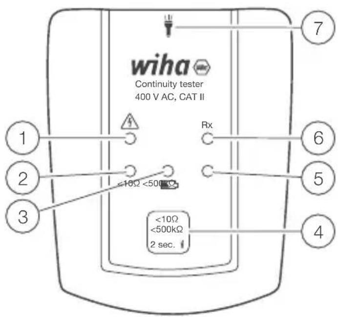
Control elements and connections
1 LED indicates high (dangerous) voltage from 50 V up to 400 V
② LED indicate measurement range < 10 Ω
③ LED indicate low battery
④ Button for different ranges and torch light
⑤ LED indicate measurement range < 500 kΩ
6 LED "Rx" indicate continuity
⑦ Torch light
Using of device
- Continuity tester can be turned on with short press on pushbutton ④. The continuity tester turns on automatically if continuity < 500 k is detected between probes. After turn on, continuity tester operates in < 500 k operating mode by default.
- Short press on pushbutton switches between operating modes: < 500 k or < 10 . < 500 k < 10 < 500 k
- Long press on pushbutton > 2 s turns on Torch light. Torch light turns off automatically 30 s after activation, or by second Long press > 2 s on pushbutton.
EN
- Long press on pushbutton > 6 s turn off device.
- Self-test of device can be activated with shorting of tips (probes) while device is turned off.
- Device indicates continuity by LED “Rx” ⑥ and beeps if resistance between tips is less than 500 kΩ for < 500 kΩ range, and if resistance is less than 10 Ω for < 10 Ω range.
- Continuity tester is intended for use on non-energized environment. The ELV LED is used to signalize dangerous voltage. If ELV LED turns on during test, testing must be stopped.
- If low battery LED turns on ③, 2x AAA batteries needs to be replaced.
Maintenance
When using the instrument in compliance with the instruction manual, no special maintenance is required.
Cleaning
If the instrument is dirty after daily usage, it is advised to clean it by using a humid cloth and a mild household detergent. Prior to cleaning, ensure that instrument is disconnected from external voltage supply and any other instruments connected. Never use acid detergents or resolvent for cleaning.
INSTRUCTION MANUAL
Battery replacement

Remove the probes from any testing point, when opening the Battery case. Batteries are dead when the continuity test with both test probes connected cannot be done anymore. A battery symbol in the LCD indicates low battery.
If the instrument operation is impaired, carry out the battery replacement.
- Disconnect the instrument from measurement circuit.
- Open the casing by loosen the screw.
- Insert 2 new batteries type AAA by respecting the polarity and close the casing.
Please think of our environment when you dispose your used batteries. They belong in a rubbish dump or a refuse collection place for hazardous waste.
Remove the battery when not using the instrument over a long time period.
However, should the instrument be contaminated by leaking batteries, return the instrument for cleaning and inspection to the factory.
Technical data
High range
Range 0...500 kΩ
Tolerance +/- 25 %
Test current < 5 μA
Acoustic indication yes
LED indication Rx LED
Automatic power on < 500 kΩ
Overvoltage protection 400 VAC / VDC for 30 s
Low Range
Range 0...10 Ω
Tolerance +/- 25 %
Test current < 20 mA
Acoustic indication yes
LED indication Rx LED
Automatic power on < 500 kΩ
Overvoltage protection 400 VAC / VDC for 30 s
General
Built according IEC / EN 61010-1
Power supply 2 x AAA batteries
Operating temperature 0...40 °C
INSTRUCTION MANUAL
Service and warranty
Should the device no longer work, should you have any questions or require information, contact an authorised customer service point for Wiha power tools:
Customer care
Wiha Werkzeuge GmbH
Obertalstraße 3 – 7
78136 Schonach
GERMANY
Tel.: +49 7722 959-0
Fax: +49 7722 959-160
Email: info.de@wiha.com
Website: www.wiha.com
The warranty is voided in the event of injury or damage to property caused due to non-compliance with these instructions. The manufacturer accepts no liability for consequential damage!
MODE D'EMPLOI
Table des matières
Website: www.wiha.com
Tools that work for you
Wiha Werkzeuge GmbH
Obertalstraße 3 – 7
78136 Schonach
GERMANY
Tel.: +49 7722 959-0
Fax: +49 7722 959-160
Website: www.wiha.com