RP350YBL - Industrial vacuum cleaner HiKOKI - Free user manual and instructions
Find the device manual for free RP350YBL HiKOKI in PDF.
| Product type | Industrial wet & dry vacuum cleaner |
| Brand | HiKOKI |
| Model | RP350YBL |
| Category | Industrial vacuum |
| Dimensions (L × W × H) | 550 × 400 × 550 mm |
| Weight | 15.2 kg |
| Voltage | 220–240 V ~ |
| Frequency | 50/60 Hz |
| Nominal power | 1400 W |
| Air flow (at hose) | 151 m³/h |
| Air flow (at fan) | 263 m³/h |
| Vacuum (at hose) | 235 hPa |
| Vacuum (at fan) | 270 hPa |
| Filter surface area | 8400 cm² |
| Dust class | L (light) |
| Main functions | Automatic filter cleaning (ACP), automatic mode (AR), volumetric flow indicator, power outlet for tool, water sensor shut-off |
| Included accessories | Suction hose φ35 mm/3.2 m, 2 polyester filter cartridges class M, 1 non-woven filter bag, crevice nozzle, universal nozzle, handle adapter, 2 plastic tubes, tube holder |
| Sound level | 69 dB(A) (K=2 dB(A)) |
| Use | Non-flammable dry dusts, non-flammable liquids, solid materials (max temperature 60°C) |
| Maintenance | Regular filter cleaning, emptying the tank, replacing filter cartridges and filter bag |
| Safety | Mandatory use with filter, do not vacuum asbestos or flammable dusts, disconnect before maintenance |
| Warranty | Complies with regulations, covers manufacturing defects (excluding normal wear) |
Frequently Asked Questions - RP350YBL HiKOKI
User questions about RP350YBL HiKOKI
0 question about this device. Answer the ones you know or ask your own.
Ask a new question about this device
Download the instructions for your Industrial vacuum cleaner in PDF format for free! Find your manual RP350YBL - HiKOKI and take your electronic device back in hand. On this page are published all the documents necessary for the use of your device. RP350YBL by HiKOKI.
USER MANUAL RP350YBL HiKOKI
natural_image
Black and white photo of a vacuum cleaner with coiled tubing and control panel (no visible text or symbols)
en Handling instructions
de Bedienungsanleitung
fr Mode d'emploi
it Istruzioni per l'uso
nl Gebruiksaanwijzing
es Instrucciones de manejo
pt Instruções de uso
SV Bruksanvisning
da Brugsanvisning
no Bruksanvisning
fi Käyttöohjeet
el Οδηγίες χειρισμού
pl Instrukcja obsługi
hu Kezelési utasítás
cs Návod k obsluze
tr Kullanım talimatları
ro Instructiuni de utilizare
sl Navodila za rokovanje
sk Pokyny na manipuláciu
bg Инструкция за експлоатация
sr Uputstvo za rukovanje
hr Upute za rukovanje

natural_image
Simple diagram of a mechanical component with a labeled dimension (5), no text or symbols present.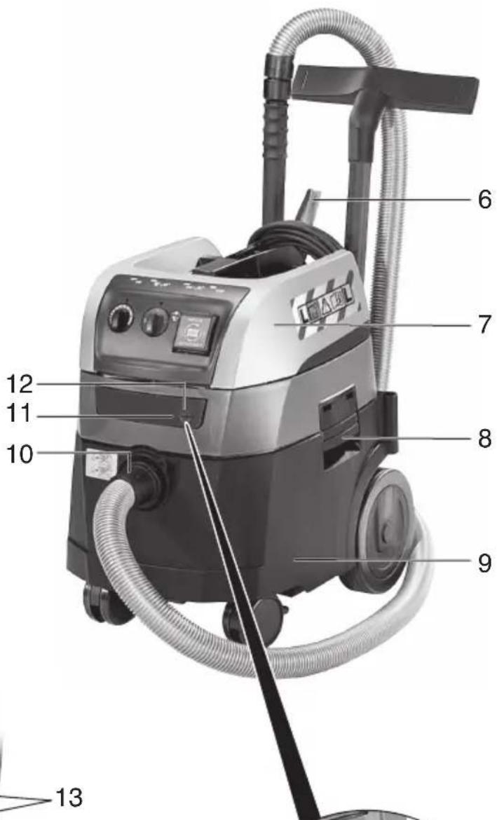
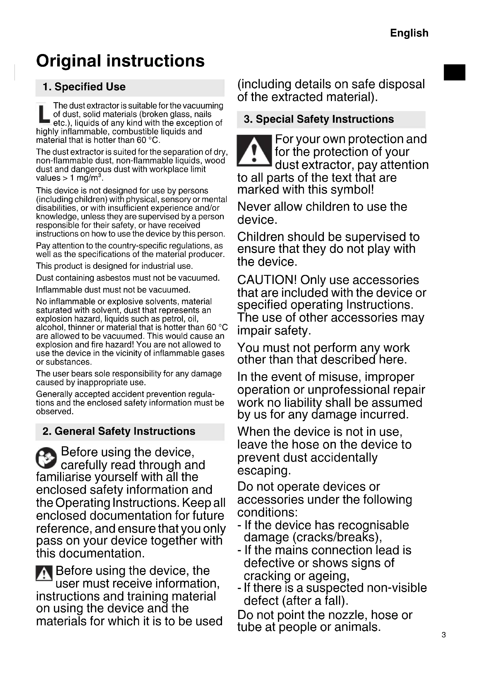
Original instructions
1. Specified Use
The dust extractor is suitable for the vacuuming of dust, solid materials (broken glass, nails etc.), liquids of any kind with the exception of highly inflammable, combustible liquids and material that is hotter than 60 °C.
The dust extractor is suited for the separation of dry, non-flammable dust, non-flammable liquids, wood dust and dangerous dust with workplace limit values > 1 mg/m ^3 .
This device is not designed for use by persons (including children) with physical, sensory or mental disabilities, or with insufficient experience and/or knowledge, unless they are supervised by a person responsible for their safety, or have received instructions on how to use the device by this person.
Pay attention to the country-specific regulations, as well as the specifications of the material producer.
This product is designed for industrial use.
Dust containing asbestos must not be vacuumed.
Inflammable dust must not be vacuumed.
No inflammable or explosive solvents, material saturated with solvent, dust that represents an explosion hazard, liquids such as petrol, oil, alcohol, thinner or material that is hotter than 60 °C are allowed to be vacuumed. This would cause an explosion and fire hazard! You are not allowed to use the device in the vicinity of inflammable gases or substances.
The user bears sole responsibility for any damage caused by inappropriate use.
Generally accepted accident prevention regulations and the enclosed safety information must be observed.
2. General Safety Instructions

Before using the device, carefully read through and liarise yourself with all the closed safety information and Operating Instructions. Keep all closed documentation for future rence, and ensure that you only is on your device together with documentation.

Before using the device, the user must receive information, tructions and training material using the device and the materials for which it is to be used (including details on safe disposal of the extracted material).
3. Special Safety Instructions

For your own protection and for the protection of your dust extractor, pay attention
to all parts of the text that are marked with this symbol!
Never allow children to use the device.
Children should be supervised to ensure that they do not play with the device.
CAUTION! Only use accessories that are included with the device or specified operating Instructions. The use of other accessories may impair safety.
You must not perform any work other than that described here.
In the event of misuse, improper operation or unprofessional repair work no liability shall be assumed by us for any damage incurred.
When the device is not in use, leave the hose on the device to prevent dust accidentally escaping.
Do not operate devices or accessories under the following conditions:
- If the device has recognisable damage (cracks/breaks),
- If the mains connection lead is defective or shows signs of cracking or ageing,
- If there is a suspected non-visible defect (after a fall).
Do not point the nozzle, hose or tube at people or animals.
English
WARNING - If any foam or water egresses, switch off immediately. Empty the container and, if need be, the pleated filter.
Never sit or stand on the device.
Always set up the connection lead and hose so there is no danger of tripping.
Do not pull the connection lead over any sharp edges and do not kink or pinch it.
If the connection lead of the device is damaged, it must be replaced by a special connection lead. See the chapter on Repairs.
Always connect to a socket with protective contact.
Do not use any damaged extension leads.
Never insert or remove the mains plug with wet hands.
Only pull on the mains plug, not on the lead.
WARNING - The plug socket on the device must be used only for the purposes defined in the operating Instructions.
Do not leave the device unattended. If there is a long work interruption, disconnect the mains plug.
The dust extractor should not be used or stored outside in wet conditions.
IMPORTANT - This device must only be stored indoors.
Acids, acetone and solvents can corrode the device components.
Prior to any servicing work, clean the device. Switch off the device after each use and pull out the mains plug.
Steam cleaners and high-pressure cleaners must not be used to clean the dust extractor.
The inside of the cover must always be kept dry.
Mould contamination can result if the device is not cleaned for an extended period, especially if used in areas where foodstuffs are processed: Always clean and disinfect the dust extractor immediately after use.
Never open the device outdoors during rain or storms.
Do not use the device outdoors in cold weather.
The device must not be operated in areas with an explosion hazard.
Ensure that the dust extractor is steady.
If the extracted air is discharged into the room, ensure there is an adequate air change rate (L) in the room. Observe the regulations that apply in your country.
Keep the tool socket dry and do not expose to moisture.
Do not plug extension cords between the dust extractor and the power tool.
When using the tool socket, use the dust extractor in a dry environment.
WARNING! This device contains dust that is harmful to health. Discharge and maintenance operations (including disposal of the dust collection containers) must only be carried out by qualified specialists wearing appropriate protective clothing and equipment.

WARNING - general danger!

CAUTION! Do not use the device until you have read the eating Instructions.
WARNING - Operating personnel must receive adequate instruction in the use of this dust extractor and in the materials for which it is used.
Special safety instructions
Warning sign for devices with dust class L:

While the device is suitable for extracting substances that pose a slight threat to health, it is not appropriate for reducing wood dust in inhaled air.
Dust from material such as paint containing lead, some wood species, minerals and metal may be harmful. Contact with or inhalation of the dust may cause allergic reactions and/or respiratory diseases to the operator or bystanders.
Certain kinds of dust are classified as carcinogenic such as oak and beech dust especially in conjunction with additives for wood conditioning (chromate, wood preservative).
- Name of Parts (page 2)
| 1 | Suction power regulator |
| 2 | Rotary switch On/Off/Automatic/ACP |
| 3 | Volume flow control display |
| 4 | Plug socket for power tool |
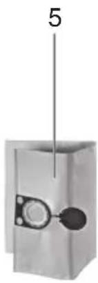
| 5 | Fleece filter bag |
| 6 | Cable holder (fold it back and use it to suspend the mains connection lead) |
| 7 | Upper part |
| 8 | S n a p l o c k |
| 9 | Container |
| 10 | Suction opening |
| 11 | Locking bar (for opening the hood to change filter cassettes) |
| 12 | Locking knob |
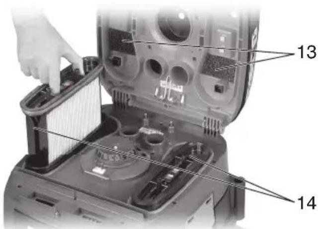
| 13 | Motor protection filter |
| 14 | Filter cassette (according to IFA C) |

5. Symbols
WARNING
The following show symbols used for the device. Be sure that you understand their meaning before use.
 | RP350YBL: Dust extractor |
 | To reduce the risk of injury, user must read instruction manual. |
 | |
 | WARNING |
 | WARNING! The dust extractor may contain hazardous dust. |
 | Dust class L (light). The dust extractors are capable of picking up dust class L. Follow your country's regulations relating to dusts and to occupational health and safety. |
 | Permanent filter cleaningThe dust extractor is fitted with an electromagnetic filter cleaning unit which can be used to shake the dust off the folding filter cassettes.The folding filter cassettes are cleaned alternately so that continuous working can be guaranteed. |
 | iPulse- Continuous monitoring of the filter filling level through differential pressure measurement, for an absolutely precise on-demand filter cleaning during the operation- Thereby constant high air flow cleaning guaranteed during the operation, even for critical types of dust |
6. Standard Accessories
| Suction hose (φ35 mm / 3.2 m) | 1 |
| Polyester filter cassettes (M class): Attached to device | 2 |
| Fleece filter bag 1 | |
| Crevice nozzle 1 | |
| Universal nozzle 1 | |
| Handle adapter 1 | |
| Plastic suction tubes 2 | |
| Tube support: Attached to device 1 |
7. Specifications
| RP350YBL | ||
| Voltage V ~ 220–240 | ||
| Frequency Hz 50/60 | ||
| Rated power | W | 1400 |
| Air flow*1 | m3/h | 151 |
| Air flow*2 | m3/h | 263 |
| Negative pressure*1 | hPa | 235 |
| Negative pressure*2 | hPa | 270 |
| L × W × H | mm | 550 × 400 × 550 |
| Weight without mains cable*3 | kg | 15.2 |
| Filter surface cm | 2 | 8400 |
*1 at the hose, *2 at the fan
*3 Weight: According to EPTA-Procedure 01/2014
Connection line on dust extractors with plug socket: H05RR-F 3X 1.5
Note: Due to HiKOKI's continuing program of research and development, the specifications herein are subject to change without prior notice.
8. Commissioning

Before plugging in, check that the rated mains voltage and mains frequency, as
stated on the type plate match your power supply.
8.1 Inserting a Fleece Filter Bag
We recommend using fleece filter bags for:
- Applications, where small amounts of fine dust are created (e.g. spot-grinding and grinding of paint and lacquer coatings, extraction of drilling applications with small diameters < 10 mm of short duration, etc.).
- Use of devices, such as: routers, planers, small grinding devices, etc.
When using a fleece filter bag (5) the filter cleaning is non-functional.
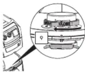
Switch off the device, remove the mains plug and open the snap locks (8). Remove the upper part (7) of the device from the container (9).
natural_image
Diagram of a mechanical device with an inset close-up showing a rotating component (no text or symbols visible)Turn the red rotary switch (on the inside of the suction opening) until the stop: the text "CLOSE" shows upwards to the marking ▲.
Hold the fleece filter bag (5) on the flange and, with its opening, guide it first over the latch at the bottom part of the suction opening, then fit up to the stop on the suction opening. Replace the upper part of the device on the container, close the snap locks.
8.2 Inserting a PE Disposal Bag (sold separately)
We recommend the use of PE-disposal bags for:
- Applications, where larger amounts of dust are created (e.g. removal of plaster surfaces, spot-grinding and grinding of screeds, etc.).
- Use of devices, such as e.g.: renovation milling devices, renovation grinders, drywall grinders, wall grinders etc.
When using a PE disposal bag, the filter cleaning must be switched on (function AR / IR) for corresponding materials (see recommendation).
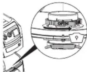
Switch off the device, remove the mains plug and open the snap locks (8). Remove the upper part (7) of the device from the container (9).
natural_image
Technical diagram of a mechanical device with an inset close-up showing internal components (no text or symbols visible)Turn the red rotary switch (on the inside o the suction opening) to the stop: the text "OPEN" shows upwards to the marking ▲.
Hold the PE disposal bag on the flange and, with its opening, guide it first over the latch at the bottom part of the suction opening, then fit up to the stop on the suction opening.
Spread out the PE disposal bag evenly across the container floor. Arrange the edges of the PE disposal bag around the container rim so that the bag is firmly clamped on all sides by the upper part (7), once replaced.
9. The device
9.1 Switching On/Off, Automatic, ACP
Select the required operating mode using the switch (2):
Position "0":
- Dust extractor is switched off OFF
Position "I":
- Dust extractor is switched on - ACP* is switched off
Position "IR":
R • Dust extractor is switched on ON + 📄 • ACP* is switched on
Position "AR":
• Automatic On/Off switch: The dust extractor is switched on or off by means of a power tool connected to the plug socket (4). (Note: The dust extractor continues to run for approx. 10 seconds after the power tool is switched off. This is to ensure that dust does not remain in the hose.)
- ACP* is switched on
* ACP (Automatic Vibrate Function): automatic filter cleaning when you switch on the device and when a specific negative pressure value is reached. For filters that remain clear, with no need to interrupt work.
9.2 Plug socket (4)
The plug socket (4) is designed for connection to a power tool only.
The total maximum permissible current consumption (of dust extractor and connected unit) must not exceed 16 A.
CAUTION! Ensure that the power tool is switched off when plugging it in. Regardless of the switch position, the plug socket is always live when the mains plug is plugged in.
If the switch (2) is in the "0" position, you can use the plug socket as an extension lead (e.g. for a light fitting).
If the switch (2) is in the "AR" position, the dust extractor is switched on or off by means of a power tool connected to the plug socket (4).
9.3 Suction power regulator
Using the suction power regulator (1), you can adjust the motor speed and thus the suction power continuously to the working conditions.
9.4 Volume flow control display
The volume flow control display (3) flashes when the container is full and/or if the suction hose is blocked.
10. Use
10.1 Dry Vacuuming
Vacuum using a dry filter, dry device and dry accessories only. If the cartridge is damp, dust may stick and form a crust.
Always use fleece filter bag (5) or PE disposal bag (sold separately) together with filter cassette (14).
10.2 Wet vacuuming

Never operate the device without inserting filter cassettes (14) first. The device may beroyed and water may also escape.
You can use either fleece filter bags (5) or PE disposal bags (sold separately). The filter cassettes (14) are suitable for wet vacuuming.
Before carrying out any wet vacuuming, remove the dry vacuumed material. This process will prevent severe soiling and encrustation.
The integrated water sensor switches off the motor when the container is full. Empty the device. If the device is not switched off, the restart protection device remains effective. The device is not operable again until it has been switched off and switched back on again.
After switching off, some water may run back out of the hose.
Before emptying, first of all take the suction hose out of the liquid.
If you are then going to dry vacuum, insert a dry filter. If there is frequent switching between dry and wet vacuuming, we recommend the use of a second (replacement) filter (preferably Polyester filter cassettes). Allow the filter, container and accessories to dry: otherwise dust may adhere to damp components.
10.3 Transport
Leave the hose on the device to prevent dust accidentally escaping.
Place the accessories in a suitable plastic bag and seal the bag.
Suspend the mains connection lead on the cable holder (6).
The upper part (7) must be securely sealed to the container (9) - check that the snap locks (8) are closed.
11. Cleaning
11.1 General Cleaning Instructions
Clean the container and accessories with water. Wipe the upper part (7) with a damp cloth.
CAUTION! This device contains dust that is harmful to health. Discharge and maintenance operations (including disposal of the dust collection containers) must only be carried out by qualified specialists wearing appropriate protective clothing and equipment.
Emptying the Container

Only permitted for dusts with occupational exposure limits > 1mg/m ^3
- Disconnect the mains plug.
- Open the snap locks (8). Remove the upper part (7) of the device from the container (9).
- Tip out the container.
Dispose of the fleece filter bag
- Disconnect the mains plug.
- Pull on mask
- Open the snap locks (8). Remove the upper part (7) of the device from the container (9).
- Carefully pull back the fleece filter bag (5) from the suction opening (10). Seal the flange of the fleece filter bag by folding over the cover.
- Dispose of the vacuumed material in accordance with legal regulations.
- Insert a new fleece filter bag (see chapter 8.1).
Disposal of PE disposal bags (sold separately)
- Insert mains supply plug.
- Switch (2) on dust extractor and shake filter: Turn switch to the "IR" position.
- Switch off dust extractor: Turn switch (2) to the "0" position.
- Pull on mask.
- Open the snap locks (8). Remove the upper part (7) of the device from the container (9). Before setting down the upper part, turn switch (2) to the "I" position so that any falling dust is vacuumed.
- Carefully pull back the PE disposal bag (sold separately) from the suction opening (10). Seal the flange of the PE disposal bag (sold separately) by folding over the cover.
- Dispose of the vacuumed material in accordance with legal regulations.
- Insert a new PE disposal bag (see chapter 8.2).
12. Maintenance
12.1 General Instructions

Before performing any maintenance, always switch off the device and remove the mains
plug. Ensure the plug cannot be reconnected accidentally.

Clean the device (see chapter 11.).
For maintenance by the user, the dust extractor must be taken apart, cleaned and maintained, to the extent possible, without endangering maintenance staff or other people.
Preventive Measures
Appropriate preventive measures include: cleaning the device before disassembly; providing local filtered forced ventilation where the dust extractor is disassembled; cleaning of the maintenance area and providing suitable personal protective clothing and equipment.
12.2 Reduction in suction power
If the suction power decreases, carry out the following steps:
- Clean the filter cassettes by activating the electromagnetic vibrator (set switch (2) to the "IR" position).
- Empty the container or replace the fleece filter bag (5) or PE disposal bag (sold separately).
- Replace the filter cassettes (14).
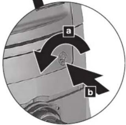
12.3 Renew the filter cassettes (14)
Shake the filter cassettes (14) once again before replacing the filters, by switching on the electromagnetic vibrator (set switch (2) to the "IR" position).
Use a coin or a similar object to turn the locking knob (12) on the locking bar (11) counter-clockwise through 90° and push the bar (11) to the rear. Swing up the hood and pull up the filter cassettes (14) to remove them. Seal the removed filter cassettes immediately in a dust-tight plastic bag and dispose of them in accordance with regulations. Insert new filter cassettes, ensuring they are correctly and securely in place.
12.4 Motor protection filter
Regularly check the motor protection filter. If the motor protection filter (13) is contaminated, this indicates that the filter cassettes (14) may be defective:
- Replace the filter cassettes (14).
- Replace the motor protection filter (13), or rinse it under running water, dry it and then replace.
12.5 Water sensor
IMPORTANT - Clean the water sensor regularly and check it for signs of damage.
13. Troubleshooting
If the volume flow control display (3) flashes, this indicates that the fleece filter bag must be emptied.
Reduction in suction power:
See the instructions in the section on Cleaning.
- Filter cassettes (14) soiled? - clean.
- Fleece filter bag (5) full? - replace.
- PE disposal bag (sold separately) full? - replace.
- Container (9) full? - empty.
- Motor protection filter (13) clogged? - See chapter 12.
- Nozzle, tubes or hose blocked? - clean.
Device will not start:
• Is the plug in the plug socket?
- No power from mains?
- Mains lead OK?
• Device hood correctly closed?
- Has the water sensor cut off? - Empty the container; then switch on and off again.
- Switch (2) in "AR" position? - Set to "I" or "IR". See chapter 9.1.
- The dust extractor is not switched on or off by means of a power tool, even though switch (2) is set to the "AR" position. - Connect the power tool to the plug socket (4).
Dust in the container when fleece filter bag is fitted:
- The position of the rotary slide is incorrect. See chapter 8.1.
PE disposal bag is sucked to the filter cassettes (14):
- The position of the rotary slide is incorrect. See chapter 8.2.
14. Accessories
Use only genuine HiKOKI accessories. See page 182.
Use only accessories that fulfil the requirements and specifications listed in these operating instructions.
15. Repairs
Replacing supply cord
If the replacement of the supply cord is necessary, it has to be done by HiKOKI Authorized Service Center to avoid a safety hazard.
CAUTION! In the operation and maintenance of power tools, the safety regulations and standards prescribed in each country must be observed.
16. Environmental Protection

Only for EU countries Do not dispose of electric tools together with household waste material! In observance of European Directive 2012/19/EU on waste electrical and electronic equipment and its implementation in accordance with national law, electric tools that have reached the end of their life must be collected separately and returned to an environmentally compatible recycling facility.
GUARANTEE
We guarantee HiKOKI Power Tools in accordance with statutory/country specific regulation. This guarantee does not cover defects or damage due to misuse, abuse, or normal wear and tear. In case of complaint, please send the Power Tool, undismantled, with the GUARANTEE CERTIFICATE found at the end of this Handling instruction, to a HiKOKI Authorized Service Center.
Information concerning airborne noise
The measured values were determined according to EN60335-2-69 and declared in accordance with ISO 4871.
Measured A-weighted sound pressure level:
69 dB (A)
Uncertainty K: 2 dB (A).
Wear hearing protection.
During operation the noise level can exceed 80 dB(A).
NOTE
Due to HiKOKI's continuing program of research and development, the specifications herein are subject to change without prior notice.
natural_image
Diagram of a car interior with a magnified inset showing a mechanical component (no text or symbols visible)natural_image
Technical diagram of a mechanical component with an inset view showing a close-up of a component (no text or symbols visible)natural_image
Diagram of a car interior with a close-up view of the dashboard and steering wheel (no text or symbols)natural_image
Technical diagram of a mechanical component with an inset circular view showing a component labeled 'OPEN' (no readable text or symbols beyond the label)natural_image
Technical diagram showing a mechanical component with an inset view of a rotating assembly (no text or symbols present)natural_image
Technical diagram of a mechanical assembly with an inset view showing a component (no text or symbols present)natural_image
Diagram of a mechanical device with a magnified inset showing a rotating component (no text or symbols)natural_image
Diagram of a vehicle's open door mechanism with a magnified inset showing the lever mechanism (no text or symbols)natural_image
Diagram of a car's front view and internal components, showing a circular inset with a labeled component (no text or symbols present)natural_image
Diagram of a car air conditioner unit with a magnified inset showing the internal components (no text or symbols)natural_image
Diagram of a car interior with a magnified inset showing a mechanical component (no text or symbols visible)natural_image
Diagram of a car interior showing a camera and a mechanical device with an arrow indicating rotation (no text or symbols present)natural_image
Diagram of a mechanical device with an inset showing a rotating component (no text or symbols visible)natural_image
Diagram of a vehicle's front view and internal components, showing a magnified inset with a location pin (no text or symbols present)natural_image
Diagram of a car interior showing a valve mechanism and a magnified view of the valve assembly (no text or symbols present)8.1 Sette inn fleece-filterpose
natural_image
Diagram of a device with an inset showing a mechanical component (no text or symbols visible)Drei den røde dreieskiven (inne i sugeåpningen) så langt det går: ordet "CLOSE" peker oppover mot ▲-merket.
natural_image
Diagram of a car interior showing a valve mechanism and a magnified view of the valve assembly (no text or symbols present)Kassere fleece-filterposer
natural_image
Diagram of a car interior showing a device with a magnified inset highlighting a component (no text or symbols present)natural_image
Diagram of a car interior showing a close-up of the engine compartment with a highlighted valve (no text or symbols present)natural_image
Diagram of a car interior with a magnified inset showing a mechanical component (no text or symbols visible)natural_image
Diagram of a vehicle dashboard with an inset showing a mechanical component (no text or symbols visible)natural_image
Technical diagram of a mechanical assembly with an inset showing a component (no text or symbols present)natural_image
Technical diagram of a mechanical assembly with an inset close-up showing internal components (no text or labels visible)natural_image
Diagram of a car interior showing a camera and a mechanical device with an arrow indicating rotation (no text or symbols present)natural_image
Diagram of a car interior showing the engine compartment and its internal components, with no visible text or symbols.natural_image
Diagram of a car interior showing a camera and a mechanical device with an arrow indicating rotation (no text or symbols present)natural_image
Diagram of a car interior showing the engine compartment and its internal components, with no visible text or symbols.natural_image
Diagram of a car interior with a close-up view of a mechanical component (no text or symbols visible)natural_image
Diagram of a car interior showing a camera and a mechanical device with an open lid, no text or symbols present.natural_image
Diagram of a car interior with a magnified inset showing a mechanical component (no text or symbols visible)natural_image
Diagram of a car interior with a magnified inset showing a mechanical component (no text or symbols visible)natural_image
Diagram of a car interior showing a camera and a mechanical device with an arrow indicating rotation (no text or symbols present)natural_image
Diagram of a car interior showing a camera and a mechanical device with an open lid, enclosed in a circular inset (no text or symbols)Only permitted for dusts with occupational exposure limits > 1mg/m ^3
natural_image
Diagram of a car interior with a magnified inset showing a mechanical component (no text or symbols visible)natural_image
Diagram of a vehicle's front view and internal components, showing engine, battery, and control panel (no text or labels)natural_image
Diagram of a car interior with a magnified inset showing a mechanical component (no text or symbols)natural_image
Diagram of a vehicle's front view and internal mechanical assembly (no text or symbols)natural_image
Diagram of a vehicle's front view and internal components, showing a component with an arrow indicating rotation (no text or symbols present)Okrenite crveni rotacioni prekidač (na unutrašnjosti otvora za usisavanje) dok se ne zaustavi: tekst „ZATVORENO“ pokazuje na gore ka oznaci ▲.
Držite netkanu kesu za filter (5) na obodu i, uz otvor, vodite je prvo preko reze na donjem dolu otvora za usisavanje, zatim postavite do zaustavljanja na otvoru za usisavanje. Zamenite gornji deo uređaja na kontejneru, zatvorite kopču za zaključavanje.
natural_image
Technical diagram of a mechanical assembly with an inset view showing a component (no text or symbols visible)Okrenite crveni rotacioni prekidač (na unutrašnjosti otvora za usisavanje) na zaustavljanje: tekst „OTVORENO“ pokazuje na gore ka oznaci ▲.
Držite PE kesu za uklanjanje na obodu i, uz otvor, vodite je prvo preko reze na donjem dolu otvora za usisavanje, zatim postavite do zaustavljanja na otvoru za usisavanje.
Raširite PE kesu za uklanjanje ravnomerno preko dna posude. Stavite ivice PE kese za uklanjanje oko okvira posude tako da je kesa čvrsto prikačena na sve strane putem gornjeg dela (7), kada se zameni.
9. Uređaj
natural_image
Diagram of a vehicle's front view and internal components, showing a device with a circular inset highlighting a component (no text or symbols present)Okrenite crveni rotacijski prekidač (na unutarnjoj strani usisnog otvora) do graničnika: tekst "CLOSE" prikazuje se prema gore do oznake ▲.
Filtar vrećicu od flisa (5) držite za prirubnicu i s njezinim otvorom prvo je provucite preko zasuna na donjem dijelu usisnog otvora, a zatim je postavite do graničnika na usisnom otvoru. Zamijenite gornji dio uređaja na spremniku, zatvorite sigurnosne brave.
Okrenite crveni rotacijski prekidač (na unutarnjoj strani usisnog otvora) do graničnika: tekst "OPEN" prikazuje se prema gore do oznake ▲.
PE vrećicu za odlaganje držite za prirubnicu i s njezinim otvorom prvo je provucite preko zasuna na donjem dijelu usisnog otvora, a zatim je postavite do graničnika na usisnom otvoru.
Raširite PE vrećicu za odlaganje ravnomjerno preko dna spremnika. Položite rubove PE vrećice za odlaganje oko ruba spremnika tako da vrećica bude čvrsto stegnuta sa svih strana gornjim dijelom (7), nakon što se zamijeni.
9. Uredaj
9.3 Regulator usisne snage
natural_image
Black-and-white photo of a dark, triangular object with a circular hole and textured surface (no visible text or symbols)| English Dansk Română | ||||
| GUARANTEE CERTIFICATE1 Model No.2 Serial No.3 Date of Purchase4 Customer Name and Address5 Dealer Name and Address(Please stamp dealer name and address) | GARANTIBEVIS1 Modelnummer2 Serienummer3 Købsdato4 Kundes navn og adresse5 Forhandlers navn og adresse(Indsæt stempel med forhandlers navn og adresse) | CERTIFICAT DE GARANTIE1 Model nr.2 Nr. de serie3 Data cumpărării4 Numele și adresa clientului5 Numele și adresa distribuitorului(Vă rugăm aplicați ștampila cu numele și adresa distribuitorului) | ||
| Deutsch Norsk Slovenščina | ||||
| GARANTIESCHEIN1 Modell-Nr.2 Serien-Nr.3 Kaufdatum4 Name und Anschrift des Kunden5 Name und Anschrift des Händlers(Bitte mit Namen und Anschrift des Handlers abstempeln) | GARANTISERTIFIKAT1 Modellnr.2 Serienr.3 Kjøpsdato4 Kundens navn og adresse5 Forhandlerens navn og adresse(Vennligst stemple forhandlerens navn og adresse) | GARANCIJSKO POTRDILO1 Št. modela2 Serijska št.3 Datum nakupa4 Ime in naslov kupca5 Ime in naslov prodajalca(Prosimo vlasnite žig z imenom in naslovom prodajalca) | ||
| Français Suomi Slovenčina | ||||
| CERTIFICAT DE GARANTIE1 No. de modèle2 No de série3 Date d'achat4 Nom et adresse du client5 Nom et adresse du revendeur(Cachet portant le nom et l'adresse du revendeur) | TAKUUTODISTUS1 Malli nro2 Sarja nro3 Ostopäivämäärä4 Asiakkaan nimi ja osoite5 Myyjän nimi ja osoite(Leimaa myyjän nimi ja osoite) | ZÁRUČNÝ LISTA1 Č. modelu2 Sériové č.3 Dátum zakúpenia4 Meno a adresa zákazníka5 Názov a adresa predajcu(Pečiatka s názvom a adresou predajcu) | ||
| Italiano Ελληγικά Български | ||||
| CERTIFICATO DI GARANZIA1 Modello2 N° di serie3 Data di acquisto4 Nome e indirizzo dell'acquirente5 Nome e indirizzo del rivenditore(Si prega di apporre il timbro con questi dati) | ПІЗТОПОІНТИКО ЕГГУНЄНЗ1 Ap. Movtėlou2 Aùξων Ap.3 Нμερομηνία αγοράς4 Оvoja kai čisúθυνση πελάτη5 Оvoja kai čisúθυνση μεταπωλητή(Παρακαλούμε να χρησιμοποιηθεί σφραγίδα) | ГАРАНЦИОНЕН СЕРТИФИКАТ1 Модел No2 Сериен No3 Дата за закупуване4 Име и адрес на клиента5 Име и адрес на търговеца(Моля, отпечатайте името и адрес на дильра) | ||
| Nederlands Polski Srpski | ||||
| GARANTIEBEWIJS1 Modelnummer2 Serienummer3 Datum van aankoop4 Naam en adres van de gebruiker5 Naam en adres van de handelaar(Stimpel a.u.b. naam en adres vande de handelaar) | GWARANCJA1 Model2 Numer seryjny3 Data zakupu4 Nazwa klienta i adres5 Nazwa dealera i adres(Pieczęć punktu sprzedažy) | GARANTNI SERTIFIKAT1 Br. modela.2 Serijski br.3 Datum kupovine4 Ime i adresa kupca5 Ime i adresa prodavca(Molimo da stavite pečat na ime i adresu trgovca) | ||
| Español Magyar Hrvatski | ||||
| CERTIFICADO DE GARANTÍA1 Número de modelo2 Número de serie3 Fecha de adquisición4 Nombre y dirección del cliente5 Nombre y dirección del distributor(Se ruega poner el sello del distribudor con su nombre y dirección) | GARANCIA BIZONYLAT1 Tipusszám2 Sorozatszám3 A vásárlás dátuma4 A Vásárló neve és címe5 A Kereskedő neve és címe(Kérjük ide elhelyezni a Kereskedő nevének és címének pecsétjét) | JAMSTVENI CERTIFIKAT1 Br modela.2 Serijski br.3 Datum kupnje4 Ime i adresa kupca5 Ime i adresa trgovca(Molimo stavite pečat na ime i adresu trgovca) | ||
| Português Čeština | ||||
| CERTIFICADO DE GARANTIA1 Número do modelo2 Número do série3 Data de compra4 Nome e morada do cliente5 Nome e morada do distribuidor(Por favor, carimbe o nome e morada do distribuidor) | ZÁRUČNÍ LIST1 Model č.2 Série č.3 Datum nákupu4 Jméno a adresa zákazníka5 Jméno a adresa prodejce(Prosíme o razitko se jménem a adresou prodejce) | |||
| Svenska Türkçe | ||||
| GARANTICERTIFIKAT1 Modellnr2 Serienr3 Inköpsdatum4 Kundens namn och adress5 Försäljarens namn och adress(Stämpla försäljarens namn och adress) | GARANTI SERTÍFÍKASI1 Model No.2 Seri No.3 Satin Alma Tarihi4 Müşteri Adı ve Adresi5 Bayi Adı ve Adresi(Lüften bayi adını ve adresini kaşe olarak basin) | |||
HiKOKI
| 1 | |
| 2 | |
| 3 | |
| 4 | |
| 5 |
Siemensring 34, 47877 willich, Germany
Tel: +49 2154 49930
Fax: +49 2154 499350
URL: http://www.hikoki-powertools.de
Hikoki Power Tools Netherlands B.V.
Brabanthaven 11, 3433 PJ Nieuwegein, The Netherlands
Tel: +31 30 6084040
Fax: +31 30 6067266
URL: http://www.hikoki-powertools.nl
Hikoki Power Tools (U.K.) Ltd.
25 Majestic Road, Southampton, SO16 OYT,
United Kingdom
Tel: +44 1908 660663
Fax: +44 1908 606642
URL: http://www.hikoki-powertools.uk
Hikoki Power Tools France S.A.S.
Hikoki Power Tools Belgium N.V./S.A.
Koningin Astridlaan 51, B-1780 Wemmel, Belgium
Tel: +32 2 460 1720
Fax: +32 2 460 2542
URL http://www.hikoki-powertools.be
Hikoki Power Tools Italia S.p.A
Via Piave 35, 36077, Altavilla Vicentina (VI), Italy
Tel: +39 0444 548111
Fax: +39 0444 548110
URL: http://www.hikoki-powertools.it
Hikoki Power Tools Ibérica, S.A.
C/ Puigbarral, 26-28, Pol. Ind. Can Petit, 08227 Terrassa
(Barcelona), Spain
Tel: +34 93 735 6722
Fax: +34 93 735 7442
URL: http://www.hikoki-powertools.es
Kjeller Vest 7, N-2007 Kjeller, Norway
Tel:(+47)6692 6600
Fax: (+47) 6692 6650
URL: http://www.hikoki-powertools.no
Hikoki Power Tools Sweden AB
Rotebergsvagen 2B SE-192 78 Sollentuna, Sweden
Tel: (+46) 8 598 999 00
Fax: (+46) 8 598 999 40
URL: http://www.hikoki-powertools.se
Hikoki Power Tools Denmark A/S
Lillebaeltsvej 90, 6715 Esbjerg N, Denmark
Tel: (+45) 75 14 32 00
Fax: (+45) 75 14 36 66
URL: http://www.hikoki-powertools.dk
Hikoki Power Tools Finland Oy
Tupalankatu 9, 15680 Lahti, Finland
Tel: (+358) 20 7431 530
Fax: (+358) 20 7431 531
URL: http://www.hikoki-powertools.fi
Hikoki Power Tools Hungary Kft.
Hikoki Power Tools Romania S.R.L.
Ring Road, No. 66, Mustang Traco Warehouses, Warehouse
No.1, Pantelimon City, 077145, Ilfov County, Romania