
MSH300 - Heating DOMETIC - Free user manual and instructions
Find the device manual for free MSH300 DOMETIC in PDF.
| Product Type | Vehicle Seat Heater |
| Brand | Dometic |
| Model | MSH300 |
| Product Number | 9600000395 |
| Dimensions of Heating Elements | Seat: 580 x 270 mm; Backrest: 580 x 270 mm |
| Power Supply | 12 V DC |
| Power Consumption | 3 levels: from 10 to 70 W per seat |
| Max Current | 10 A |
| Number of Heat Levels | 3 (high, medium, low) |
| Main Functions | Driver and passenger front seat heating, retrofitting, switch control |
| Delivery Contents | 2 heating elements (seat and backrest), switch, control box, cable set, drilling template, double-sided adhesive tape, insulating materials, manual |
| Compatibility | Passenger cars, vans, motorhomes (front seats) |
| Maintenance and Cleaning | Avoid spilling liquids; do not switch on if wet; do not place sharp or heavy objects |
| Safety | Follow the vehicle's electrical instructions; disconnect the battery before installation; do not modify the product |
| Spare Parts and Repairability | Contact the manufacturer or authorized dealer; legal warranty upon presentation of the invoice |
| General Information | User and installation manual included; made in China; Dometic France customer service |
Frequently Asked Questions - MSH300 DOMETIC
User questions about MSH300 DOMETIC
0 question about this device. Answer the ones you know or ask your own.
Ask a new question about this device
Download the instructions for your Heating in PDF format for free! Find your manual MSH300 - DOMETIC and take your electronic device back in hand. On this page are published all the documents necessary for the use of your device. MSH300 by DOMETIC.
USER MANUAL MSH300 DOMETIC
natural_image
Line drawings of electronic components including a grid-patterned device, a small rectangular device, and cable connectors (no text or symbols)MSH300, MSH301
EN Retrofit insert seat heater
Installation and Operating Manual.....9
natural_image
Technical diagram showing a mechanical assembly with intersecting lines and arrows indicating motion (no text or symbols)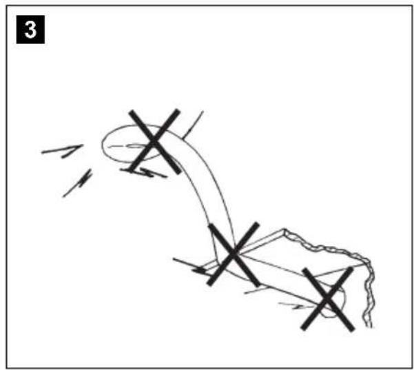
natural_image
Diagram of a mechanical or electrical component with directional arrows and cross marks, no readable text or symbols present.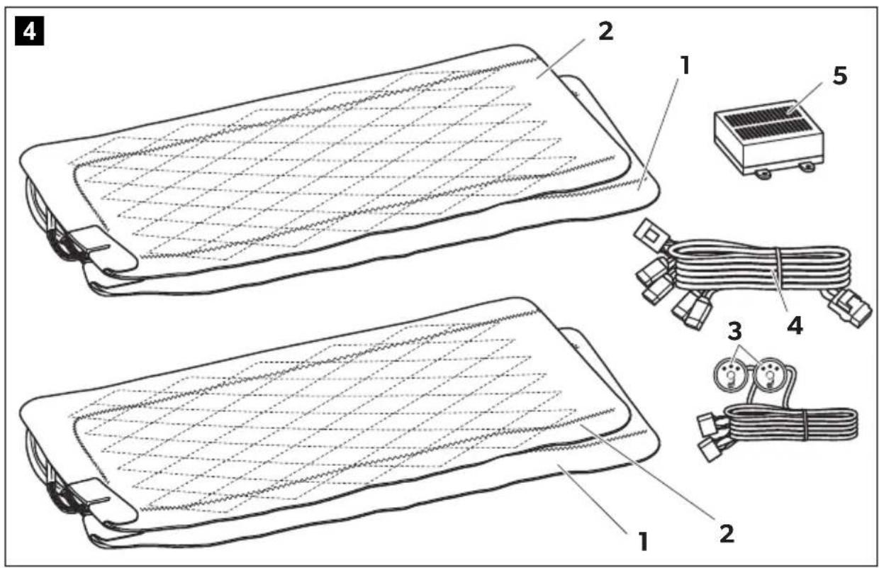
natural_image
Line drawing of a car interior frame with no text or symbols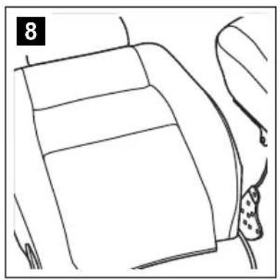
natural_image
Line drawing of a car interior showing seat, dashboard, and seatbelt (no text or symbols)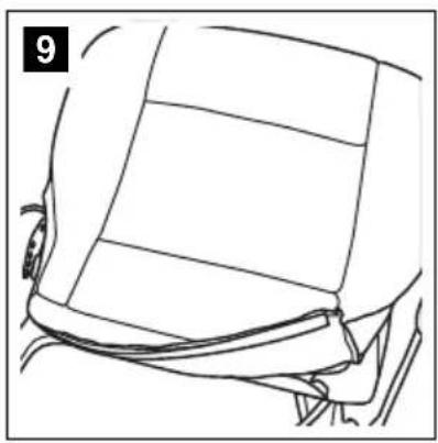
natural_image
Line drawing of a car's front and side panels showing structural details (no text or symbols)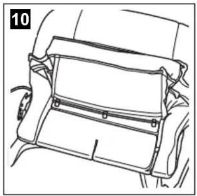
natural_image
Line drawing of a car interior compartment showing handle and seat (no text or symbols)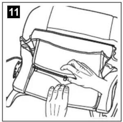
natural_image
Line drawing of hands installing or adjusting a component on a vehicle chassis (no text or symbols)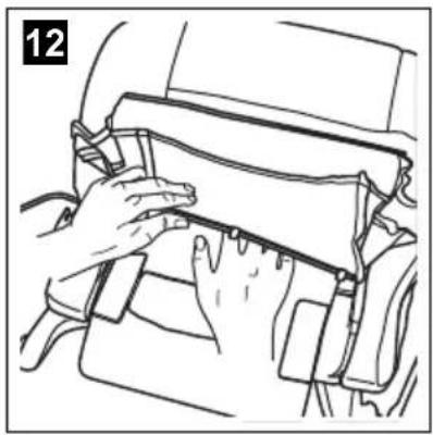
natural_image
Line drawing of hands installing or adjusting a component on a vehicle (no text or symbols visible)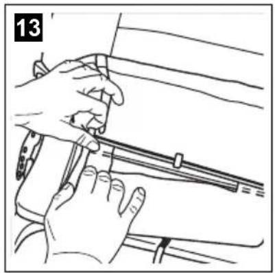
natural_image
Illustration of hands using a tool to adjust or install a mechanical component (no text or symbols visible)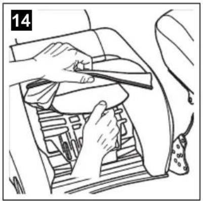
natural_image
Interior view of a car showing hands cleaning the dashboard with a tool (no text or symbols visible)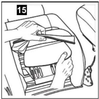
natural_image
Line drawing of hands installing or adjusting a component inside a car gear (no text or symbols)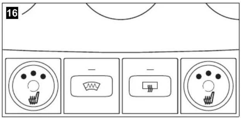
natural_image
Line drawing of a car interior showing a cable, seatbelt, and camera (no text or symbols)18
19
MSH301

| EN DE FR ES PT IT NL DA SV | |||||||||
| bu Blue | Blau Bleu | Azul Azul | Blu Blauw | Blå Blå | |||||
| og | Orange | Orange | Orange | Naranja | Cor de laranja | Arancione | Oranje | Orange | Orange |
| rd | Red | Rot | Rouge | Rojo | Vermelho | Rosso | Rood | Rød | Röd |
| bk | Black | Schwarz | Noir | Negro | Preto | Nero | Zwart | Sort | Svart |
| NO | FI | RU | PL | SK | CS | HU | |
| bu | Blå | Sininen | Синий | Niebieski | Modrá | Modrá | Kék |
| og | Oransje | Oranssi | Оранжевый | Pomarańczowy | Oranžová | Oranžová | Narancs |
| rd | Rød | Punainen | Красный | Czerwony | Červená | Červená | Piros |
| bk | Svart | Musta | Черный | Czarny | Čierna | Černá | Fekete |
20
natural_image
Line drawing of a car dashboard and steering wheel (no text or symbols)21
22
Please read this instruction manual carefully before installation and first use, and store it in a safe place. If you pass on the product to another person, hand over this instruction manual along with it.
Contents
1 Explanation of symbols....10
2 Safety and installation instructions ....10
3 Scope of delivery .....13
4 Intended use....13
5 Technical description .....14
6 Installing the seat heater....14
7 Using the seat heater ....18
8 Guarantee....19
9 Disposal....19
10 Technical data....19
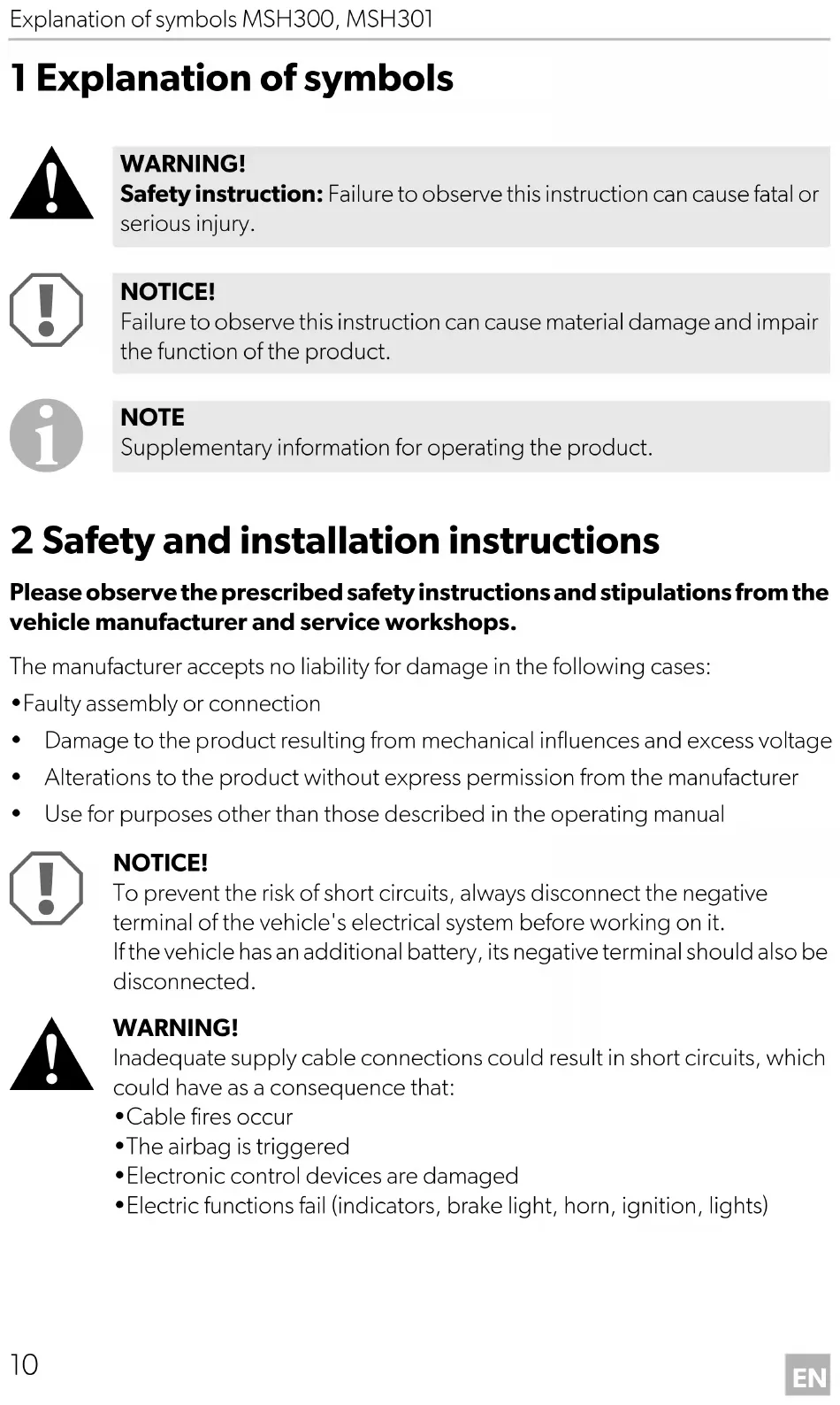
1 Explanation of symbols

WARNING!
Safety instruction: Failure to observe this instruction can cause fatal or serious injury.

NOTICE!
Failure to observe this instruction can cause material damage and impair the function of the product.

NOTE
Supplementary information for operating the product.
2 Safety and installation instructions
Please observe the prescribed safety instructions and stipulations from the vehicle manufacturer and service workshops.
The manufacturer accepts no liability for damage in the following cases:
• Faulty assembly or connection
- Damage to the product resulting from mechanical influences and excess voltage
• Alterations to the product without express permission from the manufacturer
- Use for purposes other than those described in the operating manual

NOTICE!
To prevent the risk of short circuits, always disconnect the negative terminal of the vehicle's electrical system before working on it.
If the vehicle has an additional battery, its negative terminal should also be disconnected.

WARNING!
Inadequate supply cable connections could result in short circuits, which could have as a consequence that:
- Cable fires occur
• The airbag is triggered
• Electronic control devices are damaged
• Electric functions fail (indicators, brake light, horn, ignition, lights)
Please observe the following instructions:
- When working on the following cables, only use insulated cable lugs, plugs and flat push-on receptacles:
- 30 (direct supply from positive battery terminal)
- 15 (connected positive terminal, behind the battery)
- 31 (return cable from the battery, earth)
Do not use terminal strips.
- The safest type of connection is to solder the ends of the cables together and then insulate them.
Only use insulated cable terminals, plugs and flat sockets for releasable connections. Do not use crimp terminals (cable connectors) or terminal strips.
- Use a crimping tool (fig. 1 10, page 3) to connect the cables.
- When connecting to cable 31 (earth), screw the cable
- To the vehicle's earth bolt with a cable lug and a gear disc or
- To the sheet-metal bodywork with a cable lug and a self-tapping screw.
Ensure that there is a good earth connection.
If you disconnect the negative terminal of the battery, all data stored in the volatile memories will be lost.
- The following data must be set again, depending on the vehicle equipment options:
- Radio code
- Vehicle clock
- Timer
- On-board computer
- Seat position
You can find instructions for making these settings in the appropriate operating instructions.
Observe the following installation instructions:
- Secure the parts installed in the vehicle in such a way that they cannot become loose under any circumstances (sudden braking, accidents) and cause injuries to the occupants of the vehicle.
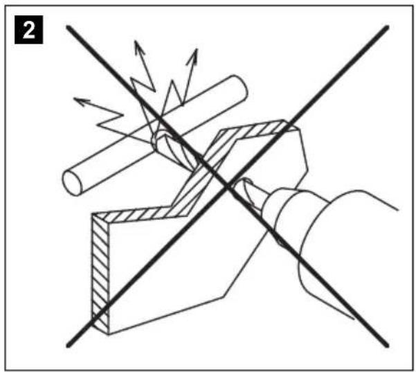
- To prevent damage, when drilling ensure that there is sufficient space on the other side for the drill head to come out (fig. 2, page 4).
- Deburr all drill holes and treat them with a rust-protection agent.
Observe the following instructions when working with electrical parts:
- When testing the voltage in electrical cables, only use a diode test lamp (fig. 1 8, page 3) or a voltmeter (fig. 1 9, page 3).
Test lamps with an illuminant (fig. 1 12, page 3) take up voltages which are too high and which can damage the vehicle's electronic system.
- When making electrical connections (fig. 3, page 4), ensure that
– They are not kinked or twisted
- They do not rub on edges
– They are not laid in sharp-edged ducts without protection.
• Insulate all connections.
- Secure the cables against mechanical wear with cable binders or insulating tape, for example to existing cables.
Observe the following instructions when using the seat heater:
- Do not place any sharp or heavy objects on the seat, as the seat heater could otherwise be damaged.
- Persons with an impaired sensitivity to heat should only operate the seat heating on level 1.
- Do not place any heat insulating objects, such as blankets or coats, on the seat when the seat heater is switched on.
- The seat heater can be damaged by fluids spilt on the seat.
- Never switch the seat heater on when it is wet.
3 S c o p e o f d
No. in fig. 4, page 4
Quantity Designation Ref. no.
MSH300 MSH301
| 1 2 1 Seat surface heating element 9101700038 | |||
| 2 2 1 Backrest heating element 9101700039 | |||
| 3 2 1 Switch 9101700041 | |||
| 4 1 | 1 Set of connecting cables (black: right side blue: left side) | 9101700053 | |
| 5 1 | 1 Switchbox | 9101700051 | |
| - | 1 | 1 Drill template | |
| - | 12 | 6 | Double-sided adhesive tape |
| - | 12 | 6 | Insulating material |
| - | 1 | 1 Operating manual | |
4 Intended use
The MagicComfort seat heating MSH300 (ref. no. 9600000395) and MSH301 (ref. no. 9600000396) are suitable for installation in the front vehicle seats of passenger vehicles, transporters and caravans.

NOTICE!
For vehicles equipped with side airbags in the seat backrests, seat occupancy detection or child seat detection, observe the vehicle manufacturer's specifications.
5 Technical description
The heating elements for the MagicComfort seat heating MSH300 and MSH301 can be installed in the driver's seat and in the passenger seat.
The shape of the seat is not altered by the heating elements.
The seat heater is operated using a switch.
6 Installing the seat heater
6.1 Tools required (fig. 1, page 3)
For installation and assembly you will need the following tools:
- Drill bit set (1)
- Drill (2)
- Screwdriver (3)
- Set of ring or open-ended spanners (4)
- Measuring ruler (5)
- Hammer (6)
- Centre punch (7)
To make and test the electrical connection, the following tools are required:
• Diode test lamp (8) or voltmeter (9)
- Crimping tool (10)
- Insulating tape (11)
- Hot air blower (13)
- Soldering iron (14)
- Solder (15)
- Cable bushing sleeves (if necessary)
To fasten the cables you may require additional cable binders.
6.2 Installing the seat heater
Removing the seat
▶Secure the vehicle against rolling away.

NOTICE!
For vehicles with side air bags in the seat backrest, observe the manufacturer's instructions on removing the seats and the upholstery.
▶ Check the suitability for installation using these installation instructions and the manufacturer's information.
▶Remove the fastening screws from the vehicle seat.
▶ Lift the seat out of the vehicle.
Preparing the seat
▶Remove all plastic panelling from the seat to ensure the fastening of the cover fabric can be reached.
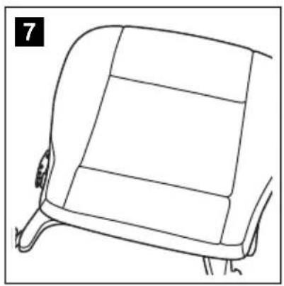
Separate the backrest from the seat (fig. 7, page 5 and fig. 8, page 5).
▶Open the seat cover on the seat surface.
The cover fabric is usually tucked into a seam on the frame with a wide cardboard strip or metal wire.
Remove the fasteners using a screwdriver and pliers (fig. 9, page 5 and fig. 10, page 5).
▶ Remove any upholstery staples or cross braces (fig. 11, page 5).
▶Open the cover of the backrest in the same way.
Preparing the heating elements

NOTICE!
Insulate all the trimmed ends with the insulating material supplied to prevent a short circuit.

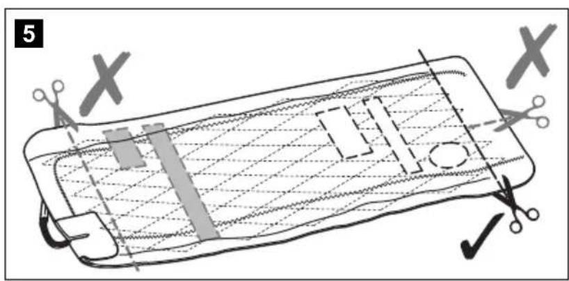
NOTE
- You can cut the heating elements to the required length and shorten the lengths of the two conductor paths.
- You can cut out a section of the heating element in the area of the anchoring grooves on the seat or the backrest. Make sure the cut-out sections are only made between the two black seams (fig. 5, page 4).
- Do not cut the mat lengthways, otherwise it will not be heated in the area of the incision (fig. 5, page 4).
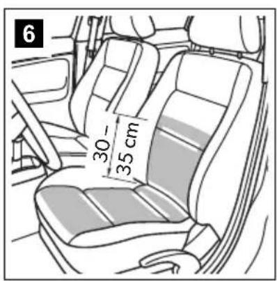
- The heating surface on the backrest only needs to extend approx. 30 – 35 cm above the seat, as the driver only leans against this area when sitting normally (fig. 6, page 4).
▶Place the heating elements on the seat and backrest.
▶ If there are anchoring grooves in the seat or the backrest, mark these areas on the heating elements.
▶Mark the required lengths. Take into account the depth of the anchoring grooves, if present. The heating element is inserted in these anchoring grooves.
▶Trim the heating element to the required length.
▶Customise the cut-out sections as required.
▶ Insulate all the trimmed ends with the insulating material.
Installing the heating element for the seat surface
▶ Insert the heating element for the seat surface between the cover fabric and the foam core of the seat (fig. 12, page 5).
If anchoring grooves are present, make sure that the cut-out sections are positioned over the anchoring grooves (fig. 13, page 5) and place the heating elements in the anchoring grooves.
▶ Fasten the heating element using double-sided adhesive tape to prevent it sliding on the foam core.
Ensure that no creases or kinks form.
Installing the heating element for the backrest

NOTICE!
If the seats are equipped with side airbags, then there is a predetermined breaking point in the cover fabric. The seat cover must therefore not be pulled tightly or slip out of place.
▶ Open the lower area of the backrest cover (fig. 14, page 5).
▶Push the heating element into the gap between the seat cover and the seat cushion (fig. 15, page 5).
▶Fasten the heating element using double-sided adhesive tape to prevent creases.
Installing the seat
▶Reassemble the backrest and seat.
▶ Lift the seat into the vehicle.
▶Secure the vehicle seat with the fastening screws.
Electrical connection
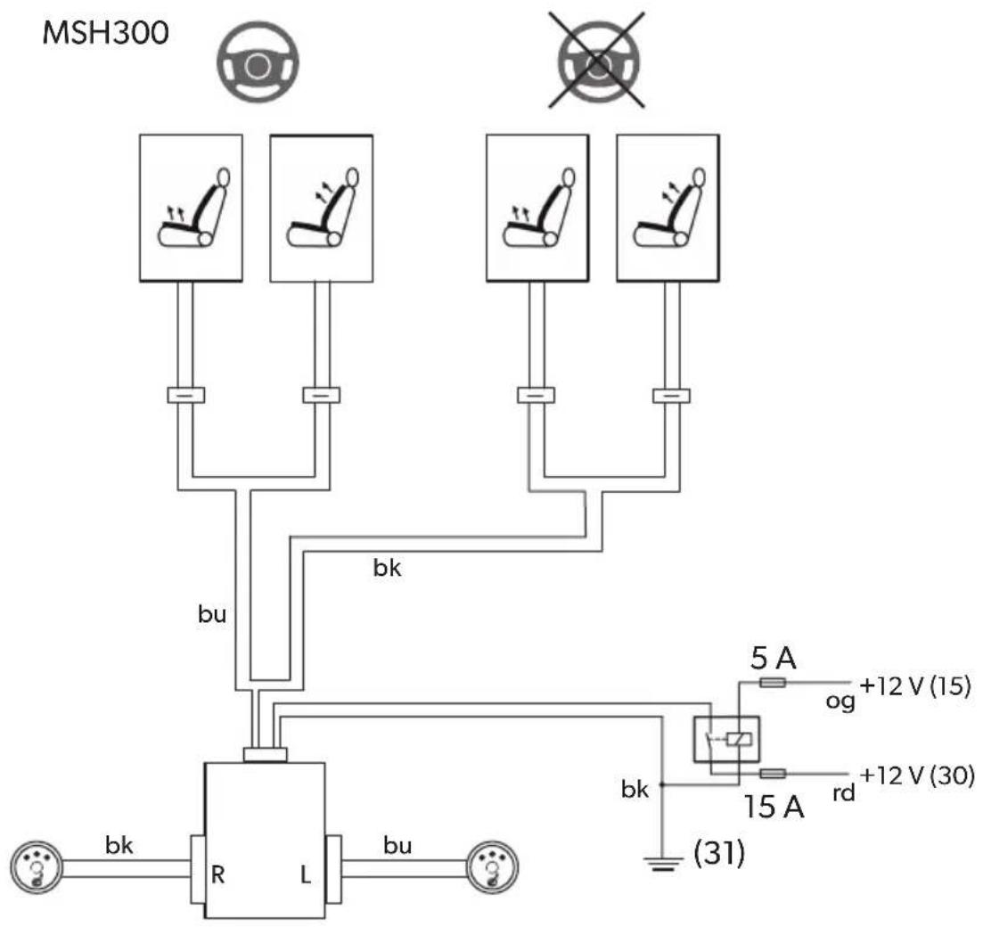
MSH300
The complete circuit diagram can be found in fig. 18, page 6.
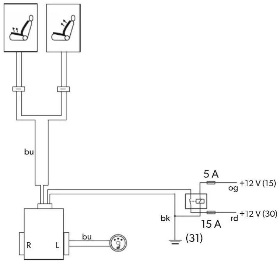
MSH301
The complete circuit diagram can be found in fig. 19, page 7.

NOTICE!
Ensure it has been securely fitted, particularly in the area of the seat rails.
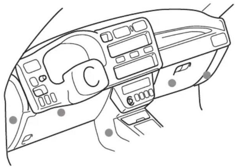
▶ Attach the switchbox to a suitable location in the vicinity of the dashboard (fig. 20, page 8).
▶ Find a suitable place for installing the seat heater switch.
If possible, use the blanking plugs provided for this purpose.
Ensure that there is enough room behind the panel for the installation of the switch.
▶ Mark the switch cut-out using the template provided (fig. 21, page 8).
▶Cut out the marked area with an appropriate tool.
▶ Install the switch into the cut-out (fig. 16, page 5).
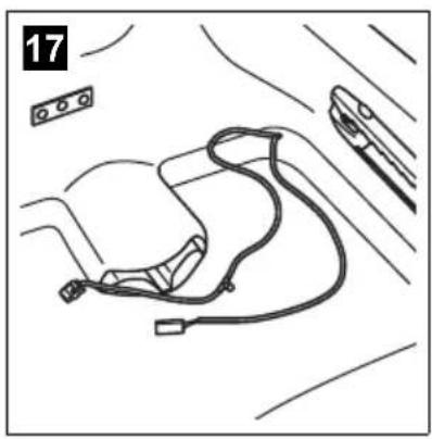
▶ Install the ready-made wiring harness so that the cables cannot bend or fray (fig. 17, page 5).
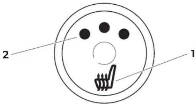
7 Using the seat heater

NOTE
The seat heating logo (fig. 22 1, page 8) also lights up when the seat heating is switched on.
▶Press the seat heater switch to turn on the seat heater:
- Press once: Level 3 (high heat output)
- Press twice: Level 2 (medium heat output)
- Press three times: Level 1 (low heat output)
√ One, two or three LEDs (fig. 22 2, page 8) on the switch light up in red.
To switch the seat heating off: Press the switch until the LEDs (fig. 22 2, page 8) on the switch go out.
8 G u a r a n t e e
The statutory warranty period applies. If the product is defective, please contact the manufacturer's branch in your country (see the back of the instruction manual for the addresses) or your retailer.
For repair and guarantee processing, please include the following documents when you send in the device:
• A copy of the receipt with purchasing date
- A reason for the claim or description of the fault
9 D i s p o s a l
▶ Place the packaging material in the appropriate recycling waste bins wherever possible.

If you wish to finally dispose of the product, ask your local recycling centre or specialist dealer for details about how to do this in accordance with the applicable disposal regulations.
10 Technical data
| MagicComfort MSH300 | MagicComfort MSH301 | |
| Ref. no.: 9600000395 9600000396 | ||
| Operating voltage: 12 V--- | ||
| Power: | adjustable to three levels, with 10 – 70 W per seat | |
| Max. power consumption: | 10 A | 5 A |
| Dimensions: | Seat element: 580 x 270 mmBackrest element: 580 x 270 mm | |
5 Description technique
Dometic Australia Pty. Ltd.
1 John Duncan Court
Varsity Lakes QLD 4227
1800212121
+61 7 55076001
Mail: sales@dometic.com.au
AUSTRIA
Dometic Austria GmbH
Neudorferstraße 108
A-2353 Guntramsdorf
+43 2236 908070
+43 2236 90807060
Mail: info@dometic.at
BENELUX
Dometic Branch Office Belgium
Zincstraat 3
B-1500 Halle
+32 2 3598040
+32 2 3598050
Mail: info@dometic.be
BRAZIL
Dometic DO Brasil LTDA
Avenida Paulista 1754, conj. 111
SP 01310-920 Sao Paulo
+551132513352
+551132513362
Dometic Group Asia Pacific
Suites 2207-11 · 22/F · Tower 1
The Gateway · 25 Canton Road,
Tsim Sha Tsui · Kowloon
+852 2 4611386
+85224665553
Mail: info@waeco.com.hk
HUNGARY
Dometic Zrt. Sales Office
Kerékgyártó u. 5.
H-1147 Budapest
+3614684400
+3614684401
Dometic Italy S.r.l.
Via Virgilio, 3
I-47122 Forlì (FC)
+39 0543 754901
+390543754983
Mail: vendite@dometic.it
JAPAN
Dometic KK
Maekawa-Shibaura, Bldg. 2
2-13-9 Shibaura Minato-ku
Tokyo 108-0023
+81 3 5445 3333
+81 3 5445 3339
Mail: info@dometic.jp
MEXICO
Circuito Médicos No. 6 Local 1
Colonia Ciudad Satélite
CP 53100 Naucalpan de Juárez
Estado de México
+52 55 5374 4108
+52 55 5393 4683
Mail: info@dometic.com.mx
NETHERLANDS
Dometic Benelux B.V.
Ecustraat 3
NL-4879 NP Etten-Leur
+31 76 5029000
+31 76 5029019
Mail: info@dometic.nl
NEW ZEALAND
Dometic New Zealand Ltd.
PO Box 12011
Penrose
Auckland 1642
+6496221490
+6496221573
Mail: customerservices@dometic.co.nz
NORWAY
Dometic Norway AS
∅sterøyveien 46
N-3232 Sandefjord
+47 33428450
+47 33428459
Mail: firmapost@dometic.no
POLAND
Dometic Poland Sp. z o.o.
Ul. Puławska 435A
PL-02-801 Warszawa
+48 22 414 3200
+48 22 414 3201
Mail: info@dometic.pl
PORTUGAL
Dometic Spain, S.L.
Komsomolskaya square 6-1
RU-107140 Moscow
+7 495 780 79 39
+7 495 916 56 53
Mail: info@dometic.ru
SINGAPORE
Dometic Pte Ltd
18 Boon Lay Way 06-140 Trade Hub 21
Singapore 609966
+65 6795 3177
+65 6862 6620
Mail: dometic@dometic.com.sg
SLOVAKIA
Dometic Slovakia s.r.o. Sales Office Bratislava
Nádražná 34/A
900 28 Ivánka pri Dunaji
/ +421 2 45 529 680
Mail: bratislava@dometic.com
SOUTH AFRICA
Dometic (Pty) Ltd.
Regional Office
South Africa & Sub-Saharan Africa
2 Avalon Road
West Lake View Ext 11
Modderfontein 1645
Johannesburg
+27114504978
+27114504976
Mail: info@dometic.co.za
SPAIN
Dometic Spain S.L.
Avda. Sierra del Guadarrama, 16
E-28691 Villanueva de la Cañada
Madrid
+34 91 833 60 89
+34 900 100 245
Mail: info@dometic.es
SWEDEN
Dometic Scandinavia AB
Gustaf Melins gata 7
Dometic Switzerland AG
Riedackerstrasse 7a
CH-8153 Rümlang
+41 44 8187171
+41 44 8187191
Mail: info@dometic.ch
UNITED ARAB EMIRATES
Dometic Middle East FZCO
P.O.Box17860
S-D 6, Jebel Ali Freezone
Dubai
+97148833858
+97148833868
Mail: info@dometic.ae
UNITED KINGDOM
Dometic UK Ltd.
Dometic House, The Brewery
Blandford St. Mary
Dorset DT119LS
+44 344 626 0133
+44 344 626 0143
Mail: customerservices@dometic.co.uk
USA
Dometic RV Division
1120 North Main Street
Elkhart, IN 46515
+1574-264-2131

- EN Retrofit insert seat heater
- Please read this instruction manual carefully before installation and first use, and store it in a safe place. If you pass on the product to another person, hand over this instruction manual along with it.
- Contents
- Explanation of symbols
- WARNING!
- NOTICE!
- NOTE
- Safety and installation instructions
- Please observe the prescribed safety instructions and stipulations from the vehicle manufacturer and service workshops.
- S c o p e o f d
- Intended use
- Technical description
- Installing the seat heater
- Tools required (fig. 1, page 3)
- Installing the seat heater
- Removing the seat
- Preparing the seat
- Preparing the heating elements
- Installing the heating element for the seat surface
- Installing the heating element for the backrest
- Installing the seat
- Electrical connection
- MSH300
- MSH301
- Using the seat heater
- G u a r a n t e e
- D i s p o s a l
- Technical data
- Description technique
- Dometic Australia Pty. Ltd.
- AUSTRIA
- Dometic Austria GmbH
- BENELUX
- Dometic Branch Office Belgium
- BRAZIL
- Dometic DO Brasil LTDA
- Dometic Group Asia Pacific
- HUNGARY
- Dometic Zrt. Sales Office
- Dometic Italy S.r.l.
- JAPAN
- Dometic KK
- MEXICO
- NETHERLANDS
- Dometic Benelux B.V.
- NEW ZEALAND
- Dometic New Zealand Ltd.
- NORWAY
- Dometic Norway AS
- POLAND
- Dometic Poland Sp. z o.o.
- PORTUGAL
- Dometic Spain, S.L.
- SINGAPORE
- Dometic Pte Ltd
- SLOVAKIA
- Dometic Slovakia s.r.o. Sales Office Bratislava
- SOUTH AFRICA
- Dometic (Pty) Ltd.
- Regional Office
- South Africa & Sub-Saharan Africa
- SPAIN
- Dometic Spain S.L.
- SWEDEN
- Dometic Scandinavia AB
- Dometic Switzerland AG
- UNITED ARAB EMIRATES
- Dometic Middle East FZCO
- UNITED KINGDOM
- Dometic UK Ltd.
- USA
- Dometic RV Division
Brand : DOMETIC
Model : MSH300
Category : Heating