PowerConnect 8100 - Controller DELL - Free user manual and instructions
Find the device manual for free PowerConnect 8100 DELL in PDF.
| Product Type | 10/40 GbE Layer 3 (L3) Network Switch |
| Brand | Dell |
| Model | PowerConnect 8100 (PC8132, PC8132F, PC8164, PC8164F) |
| Dimensions (W x D x H) | 440 x 460 x 44 mm (17.32 x 18.11 x 1.73 inches) |
| Weight | Approximately 10 kg (estimate) |
| Power Supply | Redundant, hot-swappable power supply units |
| Fixed Port Count | 24 or 48 10GbE ports (depending on model) |
| Additional Ports | 2 fixed QSFP 40G ports (PC8164/PC8164F models) |
| Port Type | 10GBase-T (RJ45) or SFP+ depending on model |
| Switching Capacity | Up to 640 Gbit/s (depending on model) |
| Key Features | Aggregation, stacking, iSCSI Auto-Configuration, QoS, VLAN, L3 routing, CLI/Web/SNMP management |
| Management | CLI, Web, SNMP interface, Dell OpenManage Network Manager |
| Operating Temperature | 10 to 35 °C (at 900 m altitude, decrease by 1 °C per 300 m) |
| Relative Operating Humidity | 8% to 85% (non-condensing) |
| Rack Mounting | Yes, 1U, ReadyRails system included (tool-less or tooled) |
| Safety | Reliable grounding, mounting precautions, maximum ambient temperature 50 °C in closed rack |
| Maintenance and Cleaning | External cleaning with a dry cloth; avoid liquids and sources of electrical noise |
| Spare Parts and Repairability | Power supply units, fans, SFP+/QSFP modules (sold separately); limited lifetime warranty with repair or replacement |
| General Information | Manual available in multiple languages; PDF documentation downloadable from Dell website |
Frequently Asked Questions - PowerConnect 8100 DELL
User questions about PowerConnect 8100 DELL
0 question about this device. Answer the ones you know or ask your own.
Ask a new question about this device
Download the instructions for your Controller in PDF format for free! Find your manual PowerConnect 8100 - DELL and take your electronic device back in hand. On this page are published all the documents necessary for the use of your device. PowerConnect 8100 by DELL.
USER MANUAL PowerConnect 8100 DELL
NOTE: A NOTE indicates important information that helps you make better use of your computer.

CAUTION: A CAUTION indicates potential damage to hardware or loss of data if instructions are not followed.
Information in this publication is subject to change without notice. © 2012 Dell Inc. All rights reserved.
Reproduction of these materials in any manner whatsoever without the written permission of Dell Inc. is strictly forbidden.
Trademarks used in this text: Dell™, the DELL logo, PowerConnect™, OpenManage™, ReadyRails™, and Torx™ are trademarks of Dell Inc. Microsoft®, Windows® are registered trademarks of Microsoft Corporation in the United States and/or other countries.
Other trademarks and trade names may be used in this publication to refer to either the entities claiming the marks and names or their products. Dell Inc. disclaims any proprietary interest in trademarks and trade names other than its own.
Regulatory Model PC8132, PC8132F, PC8164, PC8164F
February 2012 P/N JHCTM Rev. A00
Contents
1 Introduction....5
Features 5
2 Hardware Overview....6
Front Panel 7
Quad-Port SFP Uplink Fixed Ports. 8
Expansion Slot 8
UART Interface. 8
System LEDs 9
3 Installation 11
Site Preparation 11
Unpacking the Switch.... 11
Package Contents 11
Unpacking Steps 12
Rack Mounting the Switch 12
Rack Mounting Safety Considerations....12
Installing the Dell ReadyRails System ..... 13
Installing the Switch 18
4 Starting and Configuring the Switch... 19
Connecting a Switch to a Terminal 20
Booting the Switch.... 21
Performing the Initial Configuration....21
Initial Configuration Procedure....22
Example Session 23
Next Steps 26
Introduction
This document provides basic information about the Dell PowerConnect 81xx series of switches, PC8132, PC8132F, PC8164, PC8164F, including how to install a switch and perform the initial configuration. For information about how to configure and monitor switch features, see the User's Configuration Guide, which is available on the Dell Support website at support.dell.com/support for the latest updates on documentation and firmware.
This document contains the following sections:
- Hardware Overview
- Installation
- Starting and Configuring the Switch
Features
The PowerConnect 8100 Series are highly scalable, non-stop networking switches for campus aggregation and core switching 10 GbE deployments. The family of Layer 3 switches delivers 10/40 GbE wire-speed performance required to power demanding Enterprise and business infrastructures, while enabling scalability and high density 10 GbE operation with simplified management.
PC8100 Series delivers high availability and redundancy for small core and aggregation deployments that helps grow your network to high density 10 GbE operation and to 40 GbE for the Enterprise core. The family delivers high density stacking with either 10GbE or 40GbE ports, manageable as a single logical unit, as well as redundancy with power supplies, fans and firmware images. Simplified management also includes a USB Rapid Deployment feature to expedite network addressing at bootup, as well as streamline firmware image installs across the entire stack. Flexible management options include an industry-standard CLI, remote management using the embedded web server, and support for SNMP-based management applications including Dell OpenManage Network Manager.
The PC8100 family includes storage networking support and iSCSI optimization. To simplify connectivity with Dell EqualLogic arrays, the iSCSI Auto-Configuration feature in all 8100 Series switches automatically detects the arrays and configures the switch for optimal throughput. This feature is enabled by default, streamlining the process to just connecting a cable. Connectivity with Dell Compellent arrays is also simplified with a single command configuration.
Dell designed the PowerConnect 8100 Series for energy savings from the power cord to the ports, starting with EEE-capable ports to reduce active and passive port power consumption for all ports. In addition to redundant power supplies that can operate efficiently in all modes, variable speed fans reduce consumption by adjusting their speed for their environment through multiple temperature monitors. Lastly, the PC8100 family includes Dell's Lifetime Limited Warranty with Basic Hardware Service (repair or replacement) for life.
Hardware Overview
This section contains information about device characteristics and modular hardware configurations for the PowerConnect 81xx switches.
PowerConnect 81xx has the following physical dimensions:
- 440 x 460 x 44 mm (W x D x H).
- 17.32 x 18.11 x 1.73 inches (W x D x H).
PowerConnect 81xx has a chassis design with four kinds of solutions and 640 Gbps and 320 Gbps switching bandwidth as listed below:
1 PC8132F - 24 port SFP + 10G + 40G/80G extension module
2 PC8164F - 48 port SFP + 10G + 2port 40G QSFP + 40G/80G extension module
3 PC8132 - 24 port 10GBaseT + 40G/80G extension module
4 PC8164 - 48 port 10GBaseT + 2port 40G QSFP + 40G/80G extension module
The module slots can plug in three kinds of modules:
• S F P +
- 10G Base-T
• Q S F P +
The system also provides one RS-232 interface RJ45 type console port and a dedicated Ethernet service port for OOB management functions.
The PC81xx has the following features:
- Support one USB port
-
Forty-eight 10 Gbps ports for 1G/10G transceiver
-
Two fixed 40 Gbps QSFP ports for 40G transceiver
- One 80 Gbps expansion slots for SFP+, 10G Base-T and QSFP+ modules
- On board high performance CPU system with large memory. XLP308H/256 MB NOR Flash/2GB DDR III RAM.
• Temperature monitoring (TMP75)
- Software readable thermal monitor
• RTC time clock support
• Hot plugging redundant power supply
• Current monitoring for Power management
• The fan is removable and can be managed
• Standard 1U chassis high
Front Panel
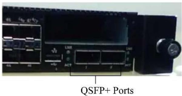
The following image shows the PowerConnect 81xx front panel:
Figure 1. PowerConnect 81xx Front Panel
text_image
QSFP+ PortsThe front panel includes:
• 24/48 fixed 10G Base-T or SFP+ ports
- Management port
- USB 2.0 port

NOTE: LED display for System, fan and power status indicators are on the back panel.
Quad-Port SFP Uplink Fixed Ports
The PC8164 and PC8164F models feature two fixed QSFP ports, each providing the following features:
- Four 10G ports with quad-breakout/QBO cable
• One 40G port supporting CR4, SR4 and LR4 transceivers - Front panel port status LEDs
The QSFP connections can be used for stacking. Stacking is supported at distances of up to 100M.

NOTE: The QSFP modules can be used only for the PowerConnect 81xx-series switches.
Expansion Slot
The 80 Gbps expansion slot supports the following modules:
- SFP+ (four 10G ports)
• 10G Base-T (four 10G ports) - QSFP+ (may be configured as two 40G ports or up to 8 10G ports)
The modules are sold separately.
UART Interface
The UART (Universal Asynchronous Receiver Transmitter) port is modeled after the industry standard 16550 UART devices. The UART port provides serial communication capabilities, which allows communication with the model or other external devices using RS-232 protocol. A serial port provides a direct connection to the switch and allows you to access the CLI from a console terminal connected to the port through the provided serial cable (with RJ45 YOST to female DB-9 connectors).
The UART port is separately configurable and can be run as an asynchronous link from 1200 baud to 4M baud.
The UART interface can be programmed with the following options:
- 5, 6, 7, or 8 character bits
- 1, 1.5, or 2 stop bits
- Parity option
• Even/odd parity (if parity option is enabled) - Sticky parity (if parity option is enabled)
The defaults are 9600 baud rate, 8 data bits, No Parity, 1 Stop Bit, No Flow Control.
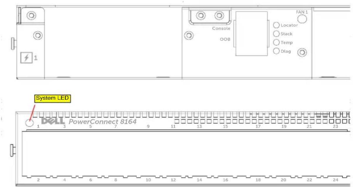
System LEDs
The system contains light emitting diodes (LEDs) that provide indications about the System, Temp, Diag, Fan, Stack, and Locator status of the PowerConnect 81xx unit. Table 1 contains the status LED definitions:
a. The thermal sensors system temperature threshold is 75^ C. When the threshold is exceeded, the Temp LED lights up to Amber.
Table 1. LED Definitions for System
| Feature Detailed Description Comment | ||
| System LED | Solid blue - Normal operationBlinking bluc - BootingSolid red - Critical system errorBlinking red - Non-critical system error (fan fail, power supply fail) | On front panel |
| Temp LED | Off - Normal temperatureSolid amber - Overtemp ^a | On back panel |
| Diag LED | Off - Normal operatingBlinking green - Diagnostic test running | On back panel |
| Fan LED | Solid green - Fan powered and at expected RPMSolid red - Fan failed | On back panel |
| Stack LED | Solid blue - Switch in stacking modeSolid green - Switch in stacking slave modeOff - Switch in stand alone mode | On back panel |
| Locator LED | Blinking blue - Locator function is enabledSolid blue - Locator function is disabled | On back panel |
Figure 2. Port LEDs
text_image
FAN 1 Console OOB Locator Stack Temp Dlag System LED DELL PowerConnect 8164 1 3 5 7 9 11 13 15 17 19 21 23 2 4 6 8 10 12 14 16 18 20 22 24Installation
Site Preparation
Before installing the switch or switches, make sure that the chosen installation location meets the following site requirements:
- Clearance—There is adequate front and rear clearance for operator access. Allow clearance for cabling, power connections, and ventilation.
- Cabling—The cabling is routed to avoid sources of electrical noise such as radio transmitters, broadcast amplifiers, power lines, and fluorescent lighting fixtures.
- Ambient Temperature—The ambient switch operating temperature range is 10^ to 35^ C ( 50^ to 95^ F).

NOTE: Decrease the maximum temperature by 1^ C ( 1.8^ F) per 300 m (985 ft.) above 900 m (2955 ft.).
- Relative Humidity—The operating relative humidity is 8% to 85% (non-condensing) with a maximum humidity gradation of 10% per hour.
Unpacking the Switch
Package Contents
When unpacking each switch, make sure that the following items are included:
- One PowerConnect switch
• One RJ45-to-DB-9 female cable - Two sets of rail kits (no tools required)
- Two PSUs (packed separately)
- Two AC power cords (country/region specific)
- Getting Started Guide
• Safety and Regulatory Information
• Warranty and Support Information - Software License Agreement
Unpacking Steps

NOTE: Before unpacking the switch, inspect the container and immediately report any evidence of damage.
1 Place the container on a clean, flat surface and cut all straps securing the container.
2 Open the container or remove the container top.
3 Carefully remove the switch from the container and place it on a secure and clean surface.
4 Remove all packing material.
5 Inspect the product and accessories for damage.
Rack Mounting the Switch
You may either place the switch on the rack shelf or mount the switch directly into a 19" wide, EIA-310-E compliant rack (four-post, two-post, or threaded methods). The Dell ReadyRails ^™ system is provided for 1U front-rack, and two-post installations. The ReadyRails system includes two separately packaged rail assemblies and two rails that are shipped attached to the sides of the switch.

WARNING: This is a condensed reference. Read the safety instructions in your Safety, Environmental, and Regulatory information booklet before you begin.

NOTE: The illustrations in this document are not intended to represent a specific switch.
Rack Mounting Safety Considerations
- Rack loading—Overloading or uneven loading of racks may result in shelf or rack failure, causing damage to equipment and possible personal injury. Stabilize racks in a permanent location before loading begins. Mount components beginning at the bottom of the rack, then work to the top. Do not exceed your rack load rating.
- Power considerations—Connect only to the power source specified on the unit. When multiple electrical components are installed in a rack, ensure that the total component power ratings do not exceed circuit capabilities. Overloaded power sources and extension cords present fire and shock hazards.
- Elevated ambient temperature—If installed in a closed rack assembly, the operating temperature of the rack environment may be greater than room ambient. Use care not to exceed the 50 degrees C maximum ambient temperature of the switch.
- Reduced air flow—Install the equipment in the rack so that the amount of airflow required for safe operation of the equipment is not compromised.
- Reliable earthing—Maintain reliable earthing of rack-mounted equipment. Pay particular attention to supply connections other than direct connections to the branch circuit, for example: use of power strips.
- Product should not be mounted with the rear panel facing in the downward position.
Installing the Dell ReadyRails System
The ReadyRails rack mounting system is provided to easily configure your rack for installation of your switch. The ReadyRails system can be installed using the 1U tool-less method or one of three possible 1U tooled methods (two-post flush mount, two-post center mount, or four-post threaded).
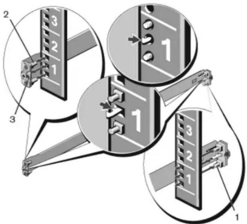
1U Tool-less Configuration (Four-post Square Hole or Unthreaded Round Hole)
1 With the ReadyRails flange ears facing outward, place one rail between the left and right vertical posts. Align and seat the rear flange rail pegs in the rear vertical post flange. In Figure 3, item 1 and its extractions illustrate how the pegs appear in both the square and unthreaded round holes.
Figure 3. 1U Tool-less Configuration
text_image
Diagram illustrating three mechanical assembly steps with numbered components and directional arrows indicating movement or force.2 Align and seat the front flange pegs in the holes on the front side of the vertical post. See Figure 3, item 2.
3 Repeat this procedure for the second rail.
4 To remove each rail, pull on the latch release button on each flange ear and unseat each rail. See Figure 3, item 3.
Two-post Flush-mount Configuration
1 For this configuration, the castings must be removed from the front side of each ReadyRails assembly. See Figure 4, item 1 on page 15. Use a Torx driver to remove the two screws from each front flange ear (on the switch side of the rail) and remove each casting. Retain the castings for future rack requirements. It is not necessary to remove the rear flange castings.
Figure 4. Two-post Flush-mount Configuration

text_image
Technical diagram showing three views of a mechanical assembly with labeled components 1, 2, and 3.2 Attach one rail to the front post flange with two user-supplied screws. See Figure 4, item 2.
3 Slide the plunger bracket forward against the vertical post and secure the plunger bracket to the post flange with two user-supplied screws. See Figure 4, item 3.
4 Repeat this procedure for the second rail.
Two-post Center-mount Configuration
1 Slide the plunger bracket rearward until it clicks into place and secure the bracket to the front post flange with two user-supplied screws. See Figure 5, item 1.
Figure 5. Two-post Center-mount Configuration

natural_image
Technical diagram of a mechanical assembly with labeled components (1 and 2), showing structural components without any readable text or symbols.2 Slide the back bracket towards the post and secure it to the post flange with two user-supplied screws. See Figure 5, item 2.
3 Repeat this procedure for the second rail.
Four-post Threaded Configuration
1 For this configuration, the flange ear castings must be removed from each end of the ReadyRails assemblies. Use a Torx driver to remove the two screws from each flange ear and remove each casting. See Figure 6, item 1 on page 17. Retain the castings for future rack requirements.
2 For each rail, attach the front and rear flanges to the post flanges with two user-supplied screws at each end. See Figure 6, item 2 on page 17.
Figure 6. Four-post Threaded Configuration

natural_image
Technical diagram of a structural frame assembly with two views (1 and 2) showing internal components and mounting details (no text or symbols present)Installing the Switch
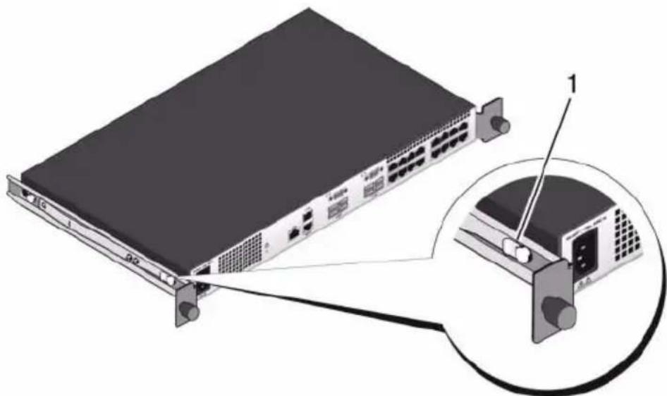
The switch may be mounted in the 1U front-rack and 1U two-post (flush and center) configurations. The following is an example of 1U front-rack configuration. The 1U two-post (flush and center) configurations, you can slide the switch into the rails in the same manner as the four-post configurations.
1U Front-rack Installation
The rails that are attached to the switch must be configured.
1 Attach the switch rails (inner chassis members) to the PC81xx switch. Figure 7, item 1 shows the detail for the front standoff with locking tab.
Figure 7. Attaching the Switch Rails
natural_image
Illustration of a network switch device with an inset showing a close-up of its internal components (no text or symbols present)2 After both switch rails are installed, line them up on Ready-Rails previously mounted to the rack and slide the switch in until flush with front of rack. About 3 inches prior to full insertion, the rail locking feature will engage to keep the switch from inadvertently sliding out of the rack and falling.
Starting and Configuring the Switch
The following flow chart provides an overview of the steps you use to perform the initial configuration after the switch is unpacked and mounted.
Figure 8. Installation and Configuration Flow Chart

flowchart
graph TD
    A["Connect Power and Console"] --> B["Power On"]
    B --> C{Enter Boot Menu?}
    C -->|Yes| D["Choose Option 2"]
    C -->|No| E["Loading Program from Flash to RAM"]
    D --> F["Boot Menu (Special Functions)"]
    F --> G["Reboot"]
    E --> H{Enter Wizard?}
    H -->|Yes| I["Manual Initial Configuration"]
    H -->|No| J["Easy Setup Wizard Configuration"]
    I --> K["Advanced Configuration"]
    J --> K
Connecting a Switch to a Terminal
After completing all external connections, connect a terminal to a switch to configure the switch.

NOTE: Read the release notes for this product before proceeding. You can download the release notes from the Dell Support website at support.dell.com/support.

NOTE: We recommend that you obtain the most recent version of the user documentation from the Dell Support website at support.dell.com/support.
To monitor and configure the switch via serial console, use the RJ45 console port on the back panel of the switch to connect it to a VT100 terminal or to a computer running VT100 terminal emulation software. The console port is implemented as a data terminal equipment (DTE) connector.
The following equipment is required to use the console port:
- VT100-compatible terminal or a desktop or a portable computer with a serial port running VT100 terminal emulation software, such as Microsoft HyperTerminal.
- A serial cable (provided) with a RJ45 connector for the console port and DB-9 connector for the terminal.
Perform the following tasks to connect a terminal to the switch console port:
1 Connect the DB-9 connector on the serial cable to the terminal or computer running VT100 terminal emulation software.
2 Configure the terminal emulation software as follows:
a Select the appropriate serial port (for example, COM 1) to connect to the console.
b Set the data rate to 9600 baud.
c Set the data format to 8 data bits, 1 stop bit, and no parity.
d Set the flow control to none.
e Set the terminal emulation mode to VT100.
f Select Terminal keys for Function, Arrow, and Ctrl keys. Ensure that the setting is for Terminal keys (not Microsoft Windows keys).

NOTE: When using HyperTerminal with Microsoft Windows 2000, make sure that you have Windows 2000 Service Pack 2 or later installed. With Windows 2000 Service Pack 2, the arrow keys function properly in HyperTerminal's VT100 emulation. Go to microsoft.com for more information about Windows 2000 service packs.
3 Connect the RJ45 connector on the cable directly to the PowerConnect 81xx RJ45 console port located on the back of the switch.
Booting the Switch
When the power is turned on, the switch goes through a power-on self-test (POST). POST runs every time the switch is initialized and checks hardware components to determine if the switch is fully operational before completely booting. If POST detects a critical problem, the program flow stops. If POST passes successfully, valid firmware is loaded into RAM. POST messages are displayed on the terminal and indicate test success or failure. The boot process runs for approximately 60 seconds.
With local terminal connected, you can invoke the Boot menu after the first part of the POST is completed. From the Boot menu, you can perform configuration tasks such as resetting the system to factory defaults, activating the backup image, or recovering a password. For more information about the Boot menu functions, see the CLI Reference Guide.
Performing the Initial Configuration
The initial configuration procedure is based on the following assumptions:
- The PowerConnect switch was never configured before and is in the same state as when you received it.
- The PowerConnect switch booted successfully.
- The console connection was established, and the Dell Easy Setup Wizard prompt appears on the screen of a VT100 terminal or terminal equivalent.
The initial switch configuration is performed through the console port. After the initial configuration, you can manage the switch from the already-connected console port or through a remote connection.

NOTE: The switch is not configured with a default user name, password, or IP address.
Before setting up the initial configuration of the switch, obtain the following information from your network administrator:
- The IP address to be assigned to the out-of-band (OOB) interface for device management.
- The IP subnet mask for the OOB interface.
- The IP address of the OOB interface default gateway.
These settings are necessary to allow the remote management of the switch through Telnet (Telnet client) or HTTP (Web browser).
Initial Configuration Procedure
You can perform the initial configuration by using the Dell Easy Setup Wizard or by using the CLI. The wizard automatically starts when the switch configuration file is empty. You can exit the wizard at any point by entering [ctrl+z] , but all configuration settings specified will be discarded, and the switch will use the default values.

NOTE: If you do not run the Easy Setup Wizard or do not respond to the initial Easy Setup Wizard prompt within 60 seconds, the switch enters CLI mode.
For more information about performing the initial configuration by using the CLI, see the CLI Reference Guide. This Getting Started Guide shows how to use the Easy Setup Wizard for initial switch configuration. The wizard sets up the following configuration on the switch:
- Establishes the initial privileged user account with a valid password. The wizard configures one privileged user account during the setup.
- Enables CLI login and HTTP access to use the local authentication setting only.
- Sets up the IP address for the OOB interface.
- Sets up the SNMP community string to be used by the SNMP manager at a given IP address. You may choose to skip this step if SNMP management is not used for this switch.
Example Session
This section describes an Easy Setup Wizard session. The following values are used by the example session:

NOTE: There is no username, password, or ip address when the switch is unboxed or set to factory defaults.
- SNMP is not enabled.
- The default user name, root, is accepted and a password of admin123 is entered. The Wizard does not display the password as it is entered.
- The OOB management interface uses assignment. 192.168.2.1 for IP address

NOTE: In the example below, the possible user options or default values are enclosed in []. If you press
The following example contains the sequence of prompts and responses associated with running an example Dell Easy Setup Wizard session, using the input values listed above.
After the switch completes the POST and is booted, the following text is displayed:
(Unit 1-Waiting to select management unit)>
Applying Global configuration, please wait ...
Welcome to Dell Easy Setup Wizard
The Setup Wizard guides you through the initial switch configuration, and gets you up and running as quickly as possible. You can skip the setup wizard, and enter CLI mode to manually configure the switch. You must respond to the next question to run the setup wizard within 60 seconds, otherwise the system will continue with normal operation using the default system configuration. Note: You can exit the setup wizard at any point by entering [ctrl+z].
Would you like to run the setup wizard (you must answer this question within 60 seconds)? [Y/N] y
First:
Do you want to select the operational mode as Simple Mode? [Y/N] y
Step 1:
The system is not setup for SNMP management by default. To manage the switch using SNMP (required for Dell Network Manager) you can
. Set up the initial SNMP version 2 account now.
. Return later and setup other SNMP accounts. (For more information on setting up an SNMP version 1 or 3 account, see the user documentation).
Would you like to setup the SNMP management interface now? [Y/N] n
Step 2:
Now we need to setup your initial privilege (Level 15) user account. This account is used to login to the CLI and Web interface. You may setup other accounts and change privilege levels later. For more information on setting up user accounts and changing privilege levels, see the user documentation.
To setup a user account:
Please enter the user name. [root]:
Please enter the user password:
Please reenter the user password:
Step 3:
Next, IP addresses are setup on the OOB (Out-Of-Band) Interface and/or the VLAN1 routing interface.
You can use these IP addresses to access the CLI, Web interface, or SNMP interface of the switch.
To access the switch through any Management Interface you can
. Setup the IP address for the Management Interface.
- Setup the default gateway if IP address is manually configured on both routing and OOB interface.
Would you like to setup the Out-Of-Band interface now? [Y/N] y
Please enter the IP address of the device (A.B.C.D) or enter "DHCP" (without the quotes) to automatically request an IP address from the network DHCP server. [192.168.2.1]:
Please enter the IP subnet mask (A.B.C.D or /nn). [255.255.255.0]:
This is the configuration information that has been collected:
Operational Mode = Simple
User Account setup = root
Password = *****
Out-of-band IP address = 192.168.2.1 255.255.255.0
Final Step:
If the information is correct, please enter (Y) to save the configuration, and copy the settings to the start-up configuration file. If the information is incorrect, enter (N) to discard the configuration and restart the wizard: [Y/N] y
Thank you for using the Dell Easy Set up Wizard. You will now enter CLI mode.
Applying Interface configuration, please wait ...
console>
Next Steps
After completing the initial configuration described in this section, you can connect any of the front-panel switch ports to your production network for in-band remote management.
If you specified DHCP for the OOB management interface IP address, the interface will acquire its IP address from a DHCP server on the network. To discover the dynamically-assigned IP address, use the console port connection to issue the following command:
show ip interface out-of-band.
To access the Dell OpenManage Switch Administrator interface, enter the OOB management interface IP address into the address field of a Web browser. For remote management access to the CLI, enter the OOB management interface IP address into a Telnet or SSH client. Alternatively, you can continue to use the console port for local CLI access to the switch.
Your PowerConnect 81xx switch supports basic switching features such as VLANs, 802.1X, RADIUS and TACACS+. For more information on the features supported in Simple mode, see Simple Switch Mode: Port Aggregator Feature White Paper.
If the switch is configured to operate in Normal mode, it can also support features such as spanning tree protocol, as well as advanced Layer 3 features such as dynamic routing and multicast. Use the web-based management interface or the CLI to configure the features your network requires. For information about how to configure the switch features, see the User's Configuration Guide or CLI Reference Guide available on the support site support.dell.com/support.
Dell PowerConnect
81xx 系列 交换机
使用入门指南
注

text_image
Technical diagram showing three mechanical assembly steps with numbered components and directional arrows indicating movement or force.text_image
Technical diagram showing three views of a mechanical assembly with labeled components 1, 2, and 3.natural_image
Technical diagram of a mechanical assembly with labeled components (1 and 2), showing structural components without any readable text or symbols.natural_image
Technical diagram of a structural assembly with two views (1 and 2) showing components like a bracket and mounting bracket, without any text or symbols.安装交换机
natural_image
Illustration of a network switch device with an inset showing its internal components (no text or symbols present)(Unit 1-Waiting to select management unit)>
Applying Global configuration, please wait ...
Welcome to Dell Easy Setup Wizard
The Setup Wizard guides you through the initial switch configuration, and gets you up and running as quickly as possible. You can skip the setup wizard, and enter CLI mode to manually configure the switch. You must respond to the next question to run the setup wizard within 60 seconds, otherwise the system will continue with normal operation using the default system configuration. Note: You can exit the setup wizard at any point by entering [ctrl+z].
Would you like to run the setup wizard (you must answer this question within 60 seconds)? [Y/N] y
First:
Do you want to select the operational mode as Simple Mode? [Y/N] y
Step 1:
The system is not setup for SNMP management by default. To manage the switch using SNMP (required for Dell Network Manager) you can
. Set up the initial SNMP version 2 account now.
. Return later and setup other SNMP accounts. (For more information on setting up an SNMP version 1 or 3 account, see the user documentation).
Would you like to setup the SNMP management interface now? [Y/N] n
Step 2:
Now we need to setup your initial privilege (Level 15) user account. This account is used to login to the CLI and Web interface. You may setup other accounts and change privilege levels later. For more information on setting up user accounts and changing privilege levels, see the user documentation.
To setup a user account:
Please enter the user name. [root]:
Please enter the user password:
Please reenter the user password:
Step 3:
Next, IP addresses are setup on the OOB (Out-Of-Band) Interface and/or the VLAN1 routing interface.
You can use these IP addresses to access the CLI, Web interface, or SNMP interface of the switch.
To access the switch through any Management Interface you can
. Setup the IP address for the Management Interface.
- Setup the default gateway if IP address is manually configured on both routing and OOB interface.
Would you like to setup the Out-Of-Band interface now? [Y/N] y
Please enter the IP address of the device (A.B.C.D) or enter "DHCP" (without the quotes) to automatically request an IP address from the network DHCP server. [192.168.2.1]:
Please enter the IP subnet mask (A.B.C.D or /nn). [255.255.255.0]:
This is the configuration information that has been collected:
Operational Mode = Simple
User Account setup = root
Password = *****
Out-of-band IP address = 192.168.2.1 255.255.255.0
Final Step:
If the information is correct, please enter (Y) to save the configuration, and copy the settings to the start-up configuration file. If the information is incorrect, enter (N) to discard the configuration and restart the wizard: [Y/N] y
Thank you for using the Dell Easy Set up Wizard. You will now enter CLI mode.
Applying Interface configuration, please wait ...
console>
接下来的步骤
text_image
Technical diagram showing three mechanical assembly steps with numbered components and directional arrows indicating movement or force.text_image
Technical diagram showing three views of a mechanical assembly with labeled components 1, 2, and 3.natural_image
Technical diagram of a mechanical assembly with labeled components (1 and 2), showing structural components without any readable text or symbols.natural_image
Technical diagram of a structural frame assembly with two views (1 and 2) showing internal components and mounting details (no text or symbols present)安装交换器
natural_image
Illustration of a network switch device with an inset showing its internal structure (no text or symbols)(Unit 1-Waiting to select management unit)>
Applying Global configuration, please wait ...
Welcome to Dell Easy Setup Wizard
The Setup Wizard guides you through the initial switch configuration, and gets you up and running as quickly as possible. You can skip the setup wizard, and enter CLI mode to manually configure the switch. You must respond to the next question to run the setup wizard within 60 seconds, otherwise the system will continue with normal operation using the default system configuration. Note: You can exit the setup wizard at any point by entering [ctrl+z].
Would you like to run the setup wizard (you must answer this question within 60 seconds)? [Y/N] y
First:
Do you want to select the operational mode as Simple Mode? [Y/N] y
Step 1:
The system is not setup for SNMP management by default. To manage the switch using SNMP (required for Dell Network Manager) you can
. Set up the initial SNMP version 2 account now.
. Return later and setup other SNMP accounts. (For more information on setting up an SNMP version 1 or 3 account, see the user documentation).
Would you like to setup the SNMP management interface now? [Y/N] n
Step 2:
Now we need to setup your initial privilege (Level 15) user account. This account is used to login to the CLI and Web interface. You may setup other accounts and change privilege levels later. For more information on setting up user accounts and changing privilege levels, see the user documentation.
To setup a user account:
Please enter the user name. [root]:
Please enter the user password:
Please reenter the user password:
Step 3:
Next, IP addresses are setup on the OOB (Out-Of-Band) Interface and/or the VLAN1 routing interface.
You can use these IP addresses to access the CLI, Web interface, or SNMP interface of the switch.
To access the switch through any Management Interface you can
. Setup the IP address for the Management Interface.
. Setup the default gateway if IP address is manually configured on both routing and OOB interface.
Would you like to setup the Out-Of-Band interface now? [Y/N] y
Please enter the IP address of the device (A.B.C.D) or enter "DHCP" (without the quotes) to automatically request an IP address from the network DHCP server. [192.168.2.1]:
Please enter the IP subnet mask (A.B.C.D or /nn). [255.255.255.0]:
This is the configuration information that has been collected:
Operational Mode = Simple
User Account setup = root
Password = *****
Out-of-band IP address = 192.168.2.1 255.255.255.0
Final Step:
If the information is correct, please enter (Y) to save the configuration, and copy the settings to the start-up configuration file. If the information is incorrect, enter (N) to discard the configuration and restart the wizard: [Y/N] y
Thank you for using the Dell Easy Set up Wizard. You will now enter CLI mode.
Applying Interface configuration, please wait ...
console>
接下來的步驟
PowerConnect 81xx Series
text_image
Ports QSFP+text_image
Technical diagram showing three mechanical assembly steps with numbered components and directional arrows indicating movement or assembly.text_image
Technical diagram showing three views of a mechanical assembly with labeled components 1, 2, and 3.natural_image
Technical diagram of a mechanical assembly with labeled components (1 and 2), showing internal components and motion paths without any readable text or symbols.natural_image
Technical illustration of a structural frame assembly with two views (1 and 2) showing internal components and mounting brackets (no text or symbols present)natural_image
Illustration of a network switch device with an inset showing its internal structure (no text or symbols present)Applying Global configuration, please wait ...
(Application de la configuration globale, veuillez patienter...)
This is the configuration information that has been collected: (Voici les informations de configuration collectées :)
Out-of-band IP address = 192.168.2.1 255.255.255.0 (Adresse IP hors bande = 192.168.2.1 255.255.255.0)
Final Step: (Etape finale)
show ip interface out-of-band.
text_image
QSFP+-Portstext_image
Technical diagram showing three mechanical assembly steps with numbered components and directional arrows indicating movement or force.text_image
Technical diagram showing three views of a mechanical assembly with labeled components 1, 2, and 3.natural_image
Technical diagram of a mechanical assembly with labeled components (1 and 2), showing internal components and motion paths without any readable text or symbols.natural_image
Technical diagram of a structural frame assembly with two views (1 and 2) showing internal components and mounting details (no text or symbols present)Installieren des Switches
natural_image
Illustration of a network switch device with an inset close-up showing internal components (no text or symbols)(Unit 1-Waiting to select management unit)>
Applying Global configuration, please wait ...
Welcome to Dell Easy Setup Wizard
The Setup Wizard guides you through the initial switch configuration, and gets you up and running as quickly as possible. You can skip the setup wizard, and enter CLI mode to manually configure the switch. You must respond to the next question to run the setup wizard within 60 seconds, otherwise the system will continue with normal operation using the default system configuration. Note: You can exit the setup wizard at any point by entering [ctrl+z].
Would you like to run the setup wizard (you must answer this question within 60 seconds)? [Y/N] y
First:
Do you want to select the operational mode as Simple Mode? [Y/N] y
Step 1:
The system is not setup for SNMP management by default. To manage the switch using SNMP (required for Dell Network Manager) you can
. Set up the initial SNMP version 2 account now.
. Return later and setup other SNMP accounts. (For more information on setting up an SNMP version 1 or 3 account, see the user documentation).
Would you like to setup the SNMP management interface now? [Y/N] n
Step 2:
Now we need to setup your initial privilege (Level 15) user account. This account is used to login to the CLI and Web interface. You may setup other accounts and change privilege levels later. For more information on setting up user accounts and changing privilege levels, see the user documentation.
To setup a user account:
Please enter the user name. [root]:
Please enter the user password:
Please reenter the user password:
Step 3:
Next, IP addresses are setup on the OOB (Out-Of-Band) Interface and/or the VLAN1 routing interface.
You can use these IP addresses to access the CLI, Web interface, or SNMP interface of the switch.
To access the switch through any Management Interface you can
. Setup the IP address for the Management Interface.
. Setup the default gateway if IP address is manually configured on both routing and OOB interface.
Would you like to setup the Out-Of-Band interface now? [Y/N] y
Please enter the IP address of the device (A.B.C.D) or enter "DHCP" (without the quotes) to automatically request an IP address from the network DHCP server. [192.168.2.1]:
Please enter the IP subnet mask (A.B.C.D or /nn). [255.255.255.0]:
This is the configuration information that has been collected:
Operational Mode = Simple
User Account setup = root
Password = *****
Out-of-band IP address = 192.168.2.1 255.255.255.0
Final Step:
If the information is correct, please enter (Y) to save the configuration, and copy the settings to the start-up configuration file. If the information is incorrect, enter (N) to discard the configuration and restart the wizard: [Y/N] y
Thank you for using the Dell Easy Set up Wizard. You will now enter CLI mode.
Applying Interface configuration, please wait ...
console>
Nächste Schritte
show ip interface out-of-band.
text_image
Port QSFP+text_image
Technical diagram showing three mechanical assembly steps with numbered components and directional arrows indicating movement or assembly.text_image
Technical diagram showing three views of a mechanical assembly with labeled components 1, 2, and 3.natural_image
Technical diagram of a mechanical assembly with labeled components (1 and 2), showing structural components without any readable text or symbols.natural_image
Technical diagram of a structural frame assembly with two views (1 and 2) showing internal components and mounting details (no text or symbols present)Menginstal Switch
natural_image
Illustration of a network switch device with an inset showing its internal components (no text or symbols present)CATATAN: We recommend that you obtain the most recent version of the user documentation from the Dell Support website at support.dell.com/support.
Please reenter the user password: (Masukkan ulang kata sandi)
Step 3: (Langkah 3:)
Next, IP addresses are setup on the OOB (Out-Of-Band) Interface and/or the VLAN1 routing interface. ((Berikutnya, alamat IP ditetapkan pada Antarmuka OOB (Out of Band) dan/atau antarmuka routing VLAN1.)
Operational Mode = Simple (Modul Operasional = Sederhana)
Password = ***** (Kata Sandi = *****)
Out-of-band IP address = 192.168.2.1 255.255.255.0 (Alamat IP Out-of-band = 192.168.2.1 255.255.255.0)
Final Step: (Langkah Terakhir)
show ip interface out-of-band.
text_image
FAN 1 Console OOB Locator Stack Temp Diag 1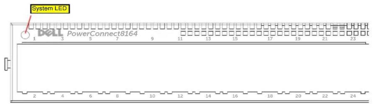
text_image
System LED 1 Dell PowerConnect8164 3 5 7 9 11 13 15 17 19 21 23 2 4 6 8 10 12 14 16 18 20 22 24設置
設置場所の準備
text_image
Technical diagram showing three mechanical assembly steps with numbered components and directional arrows indicating movement or force.text_image
Technical diagram showing three views of a mechanical assembly with labeled components 1, 2, and 3.natural_image
Technical diagram of a mechanical assembly with labeled components (1 and 2), showing internal components and motion paths without any readable text or symbols.natural_image
Technical diagram of a structural frame assembly with two views (1 and 2) showing internal components and mounting brackets (no text or symbols present)スイッチの取り付け
natural_image
Illustration of a network switch device with an inset showing its internal components (no text or symbols present)(Unit 1-Waiting to select management unit)>
Applying Global configuration, please wait ...
Welcome to Dell Easy Setup Wizard
The Setup Wizard guides you through the initial switch configuration, and gets you up and running as quickly as possible. You can skip the setup wizard, and enter CLI mode to manually configure the switch. You must respond to the next question to run the setup wizard within 60 seconds, otherwise the system will continue with normal operation using the default system configuration. Note: You can exit the setup wizard at any point by entering [ctrl+z].
Would you like to run the setup wizard (you must answer this question within 60 seconds)? [Y/N] y
First:
Do you want to select the operational mode as Simple Mode? [Y/N] y
Step 1:
The system is not setup for SNMP management by default. To manage the switch using SNMP (required for Dell Network Manager) you can
. Set up the initial SNMP version 2 account now.
. Return later and setup other SNMP accounts. (For more information on setting up an SNMP version 1 or 3 account, see the user documentation).
Would you like to setup the SNMP management interface now? [Y/N] n
Step 2:
Now we need to setup your initial privilege (Level 15) user account. This account is used to login to the CLI and Web interface. You may setup other accounts and change privilege levels later. For more information on setting up user accounts and changing privilege levels, see the user documentation.
To setup a user account:
Please enter the user name. [root]:
Please enter the user password:
Please reenter the user password:
Step 3:
Next, IP addresses are setup on the OOB (Out-Of-Band) Interface and/or the VLAN1 routing interface.
You can use these IP addresses to access the CLI, Web interface, or SNMP interface of the switch.
To access the switch through any Management Interface you can
. Setup the IP address for the Management Interface.
- Setup the default gateway if IP address is manually configured on both routing and OOB interface.
Would you like to setup the Out-Of-Band interface now? [Y/N] y
Please enter the IP address of the device (A.B.C.D) or enter "DHCP" (without the quotes) to automatically request an IP address from the network DHCP server. [192.168.2.1]:
Please enter the IP subnet mask (A.B.C.D or /nn). [255.255.255.0]:
This is the configuration information that has been collected:
Operational Mode = Simple
User Account setup = root
Password = *****
Out-of-band IP address = 192.168.2.1 255.255.255.0
Final Step:
If the information is correct, please enter (Y) to save the configuration, and copy the settings to the start-up configuration file. If the information is incorrect, enter (N) to discard the configuration and restart the wizard: [Y/N] y
Thank you for using the Dell Easy Set up Wizard. You will now enter CLI mode.
Applying Interface configuration, please wait ...
console>
次の手順
show ip interface out-of-band.
text_image
Diagram illustrating three mechanical assembly steps with numbered components and directional arrows indicating movement or force.text_image
Technical diagram showing three mechanical assembly steps with labeled components 1, 2, and 3natural_image
Technical diagram of a mechanical assembly with labeled components (1 and 2), showing structural elements and motion indicators (no text or symbols beyond labels)natural_image
Technical diagram of a structural frame assembly with two views (1 and 2) showing internal components and mounting details (no text or symbols present)스위치 설치
natural_image
Illustration of a network switch device with an inset showing a close-up of its internal components (no text or symbols present)(Unit 1 - Waiting to select management unit)>
Applying Global configuration, please wait ...
Welcome to Dell Easy Setup Wizard
The Setup Wizard guides you through the initial switch configuration, and gets you up and running as quickly as possible. You can skip the setup wizard, and enter CLI mode to manually configure the switch. You must respond to the next question to run the setup wizard within 60 seconds, otherwise the system will continue with normal operation using the default system configuration. Note: You can exit the setup wizard at any point by entering [ctrl+z].
Would you like to run the setup wizard (you must answer this question within 60 seconds)? [Y/N] y
First:
Do you want to select the operational mode as Simple Mode?
[Y/N] y
Step 1:
The system is not setup for SNMP management by default. To manage the switch using SNMP (required for Dell Network Manager) you can
. Set up the initial SNMP version 2 account now.
. Return later and setup other SNMP accounts. (For more information on setting up an SNMP version 1 or 3 account, see the user documentation).
Would you like to setup the SNMP management interface now?
[Y/N] n
Step 2:
Now we need to setup your initial privilege (Level 15) user account. This account is used to login to the CLI and Web interface. You may setup other accounts and change privilege levels later. For more information on setting up user accounts and changing privilege levels, see the user documentation.
To setup a user account:
Please enter the user name. [root]:
Please enter the user password:
Please reenter the user password:
Step 3:
Next, IP addresses are setup on the OOB (Out-Of-Band)
Interface and/or the VLAN1 routing interface.
You can use these IP addresses to access the CLI, Web interface, or SNMP interface of the switch.
To access the switch through any Management Interface you can
. Setup the IP address for the Management Interface.
. Setup the default gateway if IP address is manually configured on both routing and OOB interface.
Would you like to setup the Out-Of-Band interface now? [Y/N] y
Please enter the IP address of the device (A.B.C.D) or enter "DHCP" (without the quotes) to automatically request an IP address from the network DHCP server. [192.168.2.1]:
Please enter the IP subnet mask (A.B.C.D or /nn). [255.255.255.0]:
This is the configuration information that has been collected:
Operational Mode = Simple
User Account setup = root
Password = *****
Out-of-band IP address = 192.168.2.1 255.255.255.0
Final Step:
If the information is correct, please enter (Y) to save the configuration, and copy the settings to the start-up configuration file. If the information is incorrect, enter (N) to discard the configuration and restart the wizard: [Y/N] y
Thank you for using the Dell Easy Set up Wizard. You will now enter CLI mode.
Applying Interface configuration, please wait ...
console>
다음 단계
show ip interface out-of-band.
Fevereiro 2012 N/P JHCTM Rev. A00
Sumário
1 Introdução 229
Recursos 229
text_image
Technical diagram showing three mechanical assembly steps with numbered components and directional arrows indicating movement or force.text_image
Technical diagram showing three views of a mechanical assembly with labeled components 1, 2, and 3.natural_image
Technical diagram of a mechanical assembly with labeled components (1 and 2), showing internal components and motion paths without any readable text or symbols.natural_image
Technical diagram of a structural frame assembly with two views (1 and 2) showing internal components and mounting details (no text or symbols present)natural_image
Illustration of a network switch device with an inset showing its internal components (no text or symbols present)Do you want to select the operational mode as Simple Mode? (Deseja selecionar o Modo Simples de operação?) [Y/N] (S/N) y (s)
Step 1: (Etapa 1:)
Would you like to setup the SNMP management interface now? (Deseja configurar a interface de gerenciamento SNMP agora?) [Y/N] (S/N) n
Step 2: (Etapa 2:)
Please enter the user password: (Insira a senha:)
Please reenter the user password: (Insira novamente a senha:)
Step 3: (Etapa 3:)
Next, IP addresses are setup on the OOB (Out-Of-Band) Interface and/or the VLAN 1 routing interface. (A seguir, os endereços IP serão configurados na Interface OOB e/ou na interface de encaminhamento VLAN 1.)
You can use these IP addresses to access the CLI, Web interface, or SNMP interface of the switch. (É possível usar esses endereços IP para acessar a interface SNMP, WEB ou CLI do comutador.
Would you like to setup the Out-Of-Band interface now? (Deseja configurar a interface Out-Of-Band?) [Y/N] (S/N) y (s)
Please enter the IP address of the device (A.B.C.D) or enter "DHCP" (without the quotes) to automatically request an IP address from the network DHCP server. (Insira o endereço IP do dispositivo (A.B.C.D) ou insira "DHCP" (sem as aspas) para solicitar automaticamente um endereço IP do servidor DHCP da rede.) [192.168.2.1]:
Please enter the IP subnet mask (A.B.C.D or /nn). (Insira a máscara de sub-rede IP (A.B.C.D ou /nn)). [255.255.255.0]:
Password (Senha) = *****
Out-of-band IP address (Endereço IP OOB) = 192.168.2.1 255.255.255.0
Final Step: (Etapa final:)
text_image
Technical diagram showing three mechanical assembly steps with numbered components and directional arrows indicating movement or force.text_image
Technical diagram showing three views of a mechanical assembly with labeled components 1, 2, and 3.natural_image
Technical diagram of a mechanical assembly with labeled components (1 and 2), showing structural components without any readable text or symbols.natural_image
Technical diagram of a structural support frame assembly with two views (1 and 2), showing structural components and mounting details without any text or symbols.natural_image
Illustration of a network switch device with an inset showing its internal structure (no text or symbols)(Unit 1-Waiting to select management unit)>
Applying Global configuration, please wait ...
Welcome to Dell Easy Setup Wizard
The Setup Wizard guides you through the initial switch configuration, and gets you up and running as quickly as possible. You can skip the setup wizard, and enter CLI mode to manually configure the switch. You must respond to the next question to run the setup wizard within 60 seconds, otherwise the system will continue with normal operation using the default system configuration. Note: You can exit the setup wizard at any point by entering [ctrl+z].
Would you like to run the setup wizard (you must answer this question within 60 seconds)? [Y/N] y
First:
Do you want to select the operational mode as Simple Mode? [Y/N] y
Step 1:
The system is not setup for SNMP management by default. To manage the switch using SNMP (required for Dell Network Manager) you can
. Set up the initial SNMP version 2 account now.
. Return later and setup other SNMP accounts. (For more information on setting up an SNMP version 1 or 3 account, see the user documentation).
Would you like to setup the SNMP management interface now? [Y/N] n
Step 2:
Now we need to setup your initial privilege (Level 15) user account. This account is used to login to the CLI and Web interface. You may setup other accounts and change privilege levels later. For more information on setting up user accounts and changing privilege levels, see the user documentation.
To setup a user account:
Please enter the user name. [root]:
Please enter the user password:
Please reenter the user password:
Step 3:
Next, IP addresses are setup on the OOB (Out-Of-Band) Interface and/or the VLAN1 routing interface.
You can use these IP addresses to access the CLI, Web interface, or SNMP interface of the switch.
To access the switch through any Management Interface you can
. Setup the IP address for the Management Interface.
- Setup the default gateway if IP address is manually configured on both routing and OOB interface.
Would you like to setup the Out-Of-Band interface now? [Y/N] y
Please enter the IP address of the device (A.B.C.D) or enter "DHCP" (without the quotes) to automatically request an IP address from the network DHCP server. [192.168.2.1]:
Please enter the IP subnet mask (A.B.C.D or /nn). [255.255.255.0]:
This is the configuration information that has been collected:
Operational Mode = Simple
User Account setup = root
Password = *****
Out-of-band IP address = 192.168.2.1 255.255.255.0
Final Step:
If the information is correct, please enter (Y) to save the configuration, and copy the settings to the start-up configuration file. If the information is incorrect, enter (N) to discard the configuration and restart the wizard: [Y/N] y
Thank you for using the Dell Easy Set up Wizard. You will now enter CLI mode.
Applying Interface configuration, please wait ...
console>
Следующие шаги
show ip interface out-of-band.
support.dell.com/support.
Conmutador
Dell PowerConnect Serie 81xx
text_image
Puertos QSFP+text_image
Technical diagram showing three mechanical assembly steps with numbered components and directional arrows indicating movement or force.text_image
Technical diagram showing three views of a mechanical assembly with labeled components 1, 2, and 3.natural_image
Technical diagram of a mechanical assembly with labeled components (1 and 2), showing structural elements and motion paths without any readable text or symbols.natural_image
Technical diagram of a structural frame assembly with two views (1 and 2) showing internal components and mounting details (no text or symbols present)natural_image
Illustration of a network switch device with an inset showing its internal components (no text or symbols present)The Setup Wizard guides you through the initial switch configuration, and gets you up and running as quickly as possible. You can skip the setup wizard, and enter CLI mode to manually configure the switch. You must respond to the next question to run the setup wizard
. Setup the IP address for the Management Interface.
. Setup the default gateway if IP address is manually configured on both routing and OOB interface.
Would you like to setup the Out-Of-Band interface now? (¿Desea configurar la interfaz del Out-Of-Band ahora?) [Y/N] y (
Please enter the IP address of the device (A.B.C.D) or enter "DHCP" (without the quotes) to automatically request an IP address from the network DHCP server. (Especifique la dirección IP del dispositivo, A.B.C.D, o especifique "DHCP", sin las comillas, para solicitar automáticamente una dirección de IP al servidor DHCP de la red.) [192.168.2.1]:
Please enter the IP subnet mask (A.B.C.D or /nn). (Especifique la máscara de subred IP, A.B.C.D o /nn. [255.255.255.0]:
This is the configuration information that has been collected: (Ésta es la información de configuración que se ha recopilado:)
Operational Mode = Simple (Modo operativo = simple)
Final Step: (Paso final:)
text_image
Black electronic device front panel with labeled buttons and display screen showing status indicatorsQSFP+ Baðlantý Noktalarý
text_image
Technical diagram showing three mechanical assembly steps with numbered components and directional arrows indicating movement or force.text_image
Technical diagram showing three views of a mechanical assembly with labeled components 1, 2, and 3.natural_image
Technical diagram of a mechanical assembly with labeled components (1 and 2), showing structural components without any readable text or symbols.natural_image
Technical diagram of a structural frame assembly with two views (1 and 2) showing internal components and mounting details (no text or symbols present)Anahtarı Takma
natural_image
Illustration of a network switch device with an inset showing its internal structure (no text or symbols present)(Unit 1-Waiting to select management unit)>
Applying Global configuration, please wait ...
Welcome to Dell Easy Setup Wizard
The Setup Wizard guides you through the initial switch configuration, and gets you up and running as quickly as possible. You can skip the setup wizard, and enter CLI mode to manually configure the switch. You must respond to the next question to run the setup wizard within 60 seconds, otherwise the system will continue with normal operation using the default system configuration. Note: You can exit the setup wizard at any point by entering [ctrl+z].
Would you like to run the setup wizard (you must answer this question within 60 seconds)? [Y/N] y
First:
Do you want to select the operational mode as Simple Mode? [Y/N] y
Step 1:
The system is not setup for SNMP management by default. To manage the switch using SNMP (required for Dell Network Manager) you can
. Set up the initial SNMP version 2 account now.
. Return later and setup other SNMP accounts. (For more information on setting up an SNMP version 1 or 3 account, see the user documentation).
Would you like to setup the SNMP management interface now? [Y/N] n
Step 2:
Now we need to setup your initial privilege (Level 15) user account. This account is used to login to the CLI and Web interface. You may setup other accounts and change privilege levels later. For more information on setting up user accounts and changing privilege levels, see the user documentation.
To setup a user account:
Please enter the user name. [root]:
Please enter the user password:
Please reenter the user password:
Step 3:
Next, IP addresses are setup on the OOB (Out-Of-Band) Interface and/or the VLAN1 routing interface.
You can use these IP addresses to access the CLI, Web interface, or SNMP interface of the switch.
To access the switch through any Management Interface you can
. Setup the IP address for the Management Interface.
- Setup the default gateway if IP address is manually configured on both routing and OOB interface.
Would you like to setup the Out-Of-Band interface now? [Y/N] y
Please enter the IP address of the device (A.B.C.D) or enter "DHCP" (without the quotes) to automatically request an IP address from the network DHCP server. [192.168.2.1]:
Please enter the IP subnet mask (A.B.C.D or /nn). [255.255.255.0]:
This is the configuration information that has been collected:
Operational Mode = Simple
User Account setup = root
Password = *****
Out-of-band IP address = 192.168.2.1 255.255.255.0
Final Step:
If the information is correct, please enter (Y) to save the configuration, and copy the settings to the start-up configuration file. If the information is incorrect, enter (N) to discard the configuration and restart the wizard: [Y/N] y
Thank you for using the Dell Easy Set up Wizard. You will now enter CLI mode.
Applying Interface configuration, please wait ...
console>
Sonraki Adımlar
PC8164F, PC8164, PC8132F, PC8132
PowerConnect 8100 Series 3. 10 GbE 10/40 GbE, 10 GbE, 10 GbE
text_image
FAN 1 Console OOB Locator Stack Temp Diag 1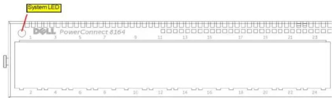
text_image
System LED DELL PowerConnect 8164 1 3 5 7 9 11 13 15 17 19 21 23 2 4 6 8 10 12 14 16 18 20 22 24תְקַרָה
תְבָרִי הַלְא
ReadyRails Among 1U Among Among Among Among Among Among Among Among Among Among Among Among Among Among Among Among Among Among Among Among Among Among Among Among Among Among Among Among Among Among Among Among Among Among Among Among Among Among Among Among Among
text_image
Technical diagram showing three mechanical assembly steps with numbered components and directional arrows indicating movement or assembly.text_image
Technical diagram showing three views of a mechanical assembly with labeled components 1, 2, and 3.natural_image
Technical diagram of a mechanical assembly with labeled components (1 and 2), showing internal components and motion paths without any readable text or symbols.2
natural_image
Technical diagram of a structural frame assembly with two views (1 and 2) showing internal components and mounting brackets (no text or symbols present)תְבָרִי הַלְהָה
natural_image
Illustration of a network switch device with an inset showing a close-up of its internal components (no text or symbols present)Applying Global configuration, please wait ...
...הכלה,הכלה,הכלה
Welcome to Dell Easy Setup Wizard
Dell 70 7273 7273 7273 7273
The Setup Wizard guides you through the initial switch configuration, and gets you up and running as quickly as possible. You can skip the setup wizard, and enter CLI mode to manually configure the switch. You must respond to the next question to run the setup wizard within 60 seconds, otherwise the system will continue with normal operation using the default system configuration. Note: You can exit the setup wizard at any point by entering [ctrl+z].
The system is not setup for SNMP management by default. To manage the switch using SNMP (required for Dell Network Manager) you can
. Return later and setup other SNMP accounts. (For more information on setting up an SNMP version 1 or 3 account, see the user documentation).
Would you like to setup the SNMP management interface now? [Y/N] n
Now we need to setup your initial privilege (Level 15) user account. This account is used to login to the CLI and Web interface. You may setup other accounts and change privilege levels later. For more information on setting up user accounts and changing privilege levels, see the user documentation.
To setup a user account:
Please enter the user name. [root]:
Please enter the user password:
Please reenter the user password:
Next, IP addresses are setup on the OOB (Out-Of-Band) Interface and/or the VLAN1 routing interface.
IP, VLAN1 (OOB)
You can use these IP addresses to access the CLI, Web interface, or SNMP interface of the switch.
To access the switch through any Management Interface you can
. Setup the default gateway if IP address is manually configured on both routing and OOB interface.
Would you like to setup the Out-Of-Band interface now? [Y/N] y
☐ [ʔ/ɔ] (?ʌvɔ 00B-ŋ ɒwɪŋ ɒs ɒtɪsɪŋ ɒtɪsɪŋ ɒsɪŋ
Please enter the IP address of the device (A.B.C.D) or enter "DHCP" (without the quotes) to automatically request an IP address from the network DHCP server. [192.168.2.1]:
Please enter the IP subnet mask (A.B.C.D or /nn).
[255.255.255.0]:
This is the configuration information that has been collected:
: 90817 71177 71177
Operational Mode = Simple
הכלה = 0109
User Account setup = root
=0000000 112011 1711
Password = *****
******* = ·
Out-of-band IP address = 192.168.2.1 255.255.255.0
192.168.2.1 255.255.255.0 = OOB πωπη Ψω IP παιπο
Final Step:
1910 17w
If the information is correct, please enter (Y) to save the configuration, and copy the settings to the start-up configuration file. If the information is incorrect, enter (N) to discard the configuration and restart the wizard: [Y/N] y
Applying Interface configuration, please wait ... ...הכלה,הכלההכלהה console>
πηρι πιζ<