
PowerConnect 2808 - Network card / adapter DELL - Free user manual and instructions
Find the device manual for free PowerConnect 2808 DELL in PDF.
| Product type | Managed/unmanaged Gigabit Ethernet network switch |
| Brand | Dell |
| Model | PowerConnect 2808 |
| Number of ports | 8 RJ-45 Gigabit Ethernet ports |
| Management | Unmanaged mode (plug-and-play) or managed mode via Web interface, Telnet, CLI, SNMP |
| Power supply | AC 100-240V, 50-60 Hz, standard power connector |
| Power consumption | Optimized by Green Ethernet function (Energy-Efficient Ethernet) |
| Operating environment | Temperature: 0 to 45 °C; Humidity: up to 95% non-condensing |
| Mounting | 19-inch rack mount (kit included), flat surface (adhesive pads) or wall |
| Ventilation | Do not block vents; minimum clearance of 5 cm on sides and 12.7 cm at rear |
| Network cabling | Category 5 UTP cables with RJ-45 connectors; auto-MDI/MDIX |
| Advanced features | Green Ethernet, Web management, SNMP, VLAN, QoS (as per documentation) |
| Safety | Follow installation precautions: do not open the case, avoid water and heat sources, disconnect before rack mounting |
| Maintenance | Clean with a dry cloth; do not use abrasive products; keep ventilation clear |
| General information | Designed for small businesses or offices (SOHO); documentation on CD and Dell website |
Frequently Asked Questions - PowerConnect 2808 DELL
User questions about PowerConnect 2808 DELL
0 question about this device. Answer the ones you know or ask your own.
Ask a new question about this device
Download the instructions for your Network card / adapter in PDF format for free! Find your manual PowerConnect 2808 - DELL and take your electronic device back in hand. On this page are published all the documents necessary for the use of your device. PowerConnect 2808 by DELL.
USER MANUAL PowerConnect 2808 DELL
Notes, Notices, and Cautions

NOTE: A NOTE indicates important information that helps to make better use of the device.

NOTICE: A NOTICE indicates either potential damage to hardware or loss of data and gives information how to avoid the problem.

CAUTION: A CAUTION indicates a potential for property damage, personal injury, or death.
Information in this document is subject to change without notice.
©2010 Dell Inc. All rights reserved.
Reproduction in any manner whatsoever without the written permission of Dell Inc. is strictly forbidden.
Trademarks used in this text: Dell, Dell OpenManage, the DELL logo, Inspiron, Dell Precision, Dimension, OptiPlex, PowerConnect, PowerApp, PowerVault, Axim, DellNet, and Latitude are trademarks of Dell Inc. Microsoft and Windows are registered trademarks of Microsoft Corporation.
Other trademarks and trade names may be used in this document to refer to either the entities claiming the marks and names or their products. Dell Inc. disclaims any proprietary interest in trademarks and trade names other than its own.
Contents
1 Installation
Overview 5
Site Preparation 5
Site Requirements 5
Unpacking 6
Package Contents....6
Unpacking the Device 6
2 Mounting the Device
Overview 7
Installation Precautions....7
Device Rack Installation 8
Installing on a Flat Surface 9
Installing on a Wall....9
3 Starting and Configuring the Device
Management Modes....12
Connecting the Device to the Network .... 12
Connecting the Terminal to the Device .... 13
Booting the Device - Managed Mode .... 13
Initial Configuration - Managed Mode .... 15
Web Configuration .... 18
The Newly Introduced Eco-Friendly Feature: Green Ethernet 19
Regulatory Notices....20
This document provides basic information to install and start running the following PowerConnect 2800 series of Web-managed Gigabit Ethernet switches:
- PowerConnect 2808
- PowerConnect 2816
- PowerConnect 2824
- PowerConnect 2848
The PowerConnect 2800 series can be used to connect workstations and other network devices, such as:
- Servers
• II u b s - R o u t e r s
The PowerConnect devices are primarily intended for the Small Office/Home Office (SOHO) that require high performance edge connectivity. These PowerConnect devices are ideal for the small to medium business that requires high performance network connectivity along with advanced web management features. The PowerConnect management features are designed to minimize administrative management effort, while enhancing and improving network traffic control.
The switch is delivered from the factory in Unmanaged Mode. If users wish to use the switch as an unmanaged switch, they can simply plug the switch in and start using it. No configuration is necessary. If the same user wishes to use the switch as a managed switch, they need to change the mode from Unmanaged to Managed, as described in the Dell™ PowerConnect™ 2800 Series User's Guide, available on the Documentation CD. Alternatively, you may check the Dell support website at www.support.dell.com for the latest documentations and software updates.
Site Preparation
Site Requirements
The PowerConnect 2808/16/24/48 devices can be mounted in a standard equipment rack, placed on a tabletop, or mounted on the wall.
Before installing the device, verify that the site selected for the device meets the following site requirements:
- Power — The device is installed within 1.5 m (5 feet) of a grounded, easily accessible outlet 220/110 VAC, 50/60 Hz.
- General — Ensure that the power supply is correctly installed.
- Clearance — There is adequate frontal clearance for operator access. Allow clearance for cabling, power connections, and ventilation.
- Cabling — Cabling is routed to avoid sources of electrical noise such as radio transmitters, broadcast amplifiers, power lines, and fluorescent lighting fixtures.
- Ambient Requirements — The ambient device operating temperature range is 0 to 45 °C (32 to 113 °F) at a relative humidity of up to 95%, non-condensing. Verify that water or moisture cannot enter the device case.
Unpacking
Package Contents
While unpacking the device, ensure that the following items are included:
- The device
- AC power cable
- Self-adhesive rubber pads (for on-shelf installation)
- Rack-mount kit for installation
- Documentation CD
• Product Information Guide
Unpacking the Device
To unpack the PowerConnect device:
NOTE: Before unpacking the device, inspect the packaging and report any evidence of damage.
1 Place the box on a clean flat surface.
2 Open the box or remove the box top.
3 Carefully remove the device from the package and place it on a secure, stable and clean surface.
4 Remove all packing material.
5 Inspect the product for damage. Report any damage immediately.
Mounting the Device
Overview
The following mounting instructions apply to the PowerConnect 2808/16/24/48 devices. There are three device mounting options:
- Installing in a Rack
- Installing on a Flat Surface
- Installing on a Wall
Installation Precautions

CAUTION Before performing any of the following procedures, read and follow the safety instructions located in your Product Information Guide.

CAUTION Observe the following points before performing the procedures in this section:
- Ensure that the rack or cabinet housing the device is adequately secured to prevent it from becoming unstable and/or falling over.
- Ensure that the power source circuits are properly grounded.
- Observe and follow the service markings. Do not service any device except as explained in the system documentation. Opening or removing covers marked with a triangular symbol with a lighting bolt may cause electrical shock. These components are to be serviced by trained service technicians only.
- Ensure that the power cable, extension cable, and/or plug is not damaged.
- Ensure that the device is not exposed to water.
- Ensure that the device is not exposed to radiators and/or heat sources.
- Ensure that the cooling vents are not blocked.
- Do not push foreign objects into the device, as it may cause a fire or electric shock.
- Use the device only with approved equipment.
- Allow the device to cool before removing covers or touching internal equipment.
- Ensure that the device does not overload the power circuits, wiring, and over-current protection. To determine the possibility of overloading the supply circuits, add together the ampere ratings of all devices installed on the same circuit as the device. Compare this total with the rating limit for the circuit.
- Do not install the device in an environment where the operating ambient temperature might exceed 40^ (104°F).
- Ensure that the airflow around the front, sides, and back of the device is not restricted.
Device Rack Installation

CAUTION: Read the safety information in the Product Information Guide as well as the safety information for other devices that connect to or support the device.

CAUTION: Disconnect all cables from the device before mounting the device in a rack or cabinet.

CAUTION: When mounting multiple devices into a rack, mount the devices from the bottom up.
Install the device in a rack as follows:
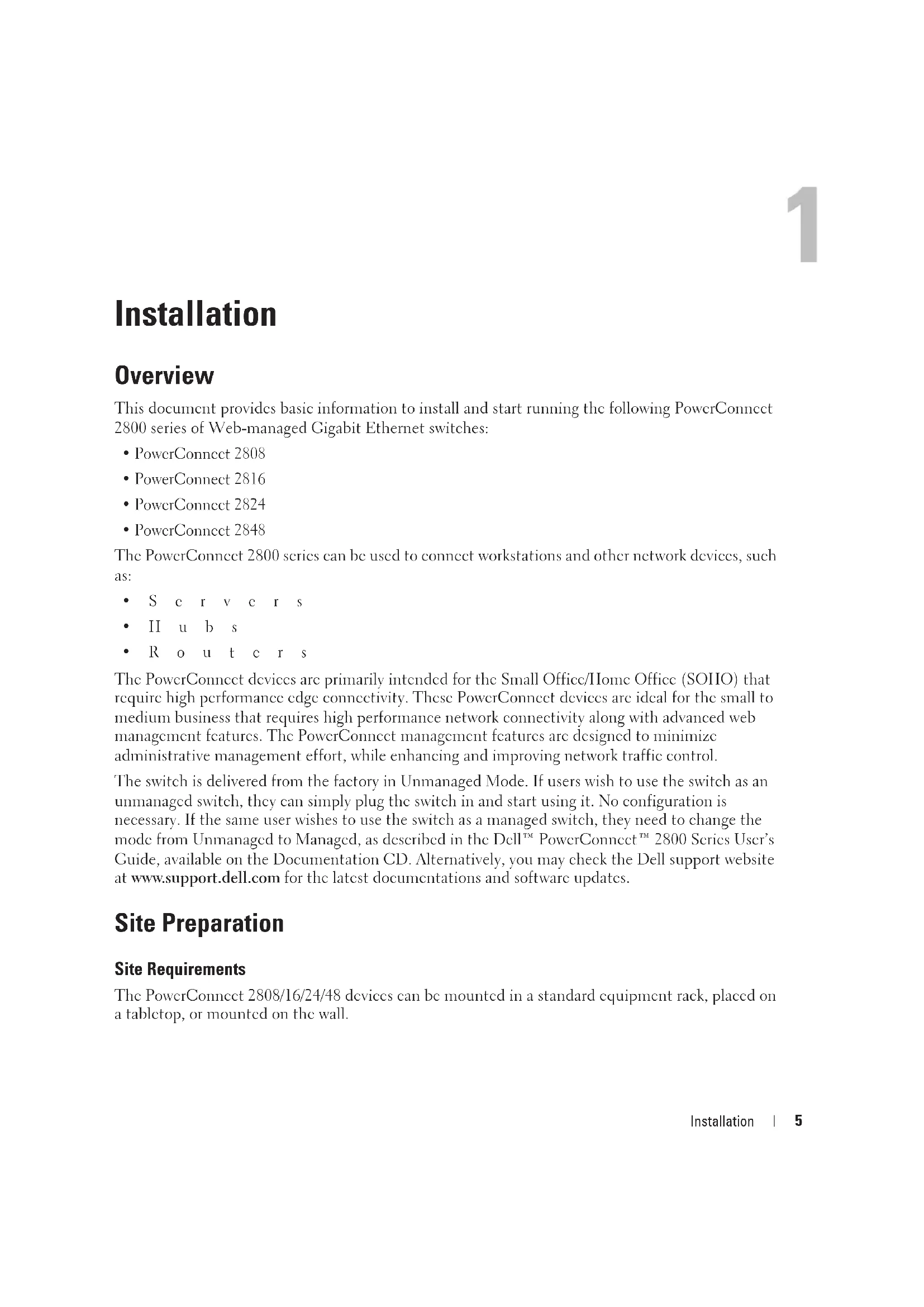
1 Place the supplied rack-mounting bracket on one side of the device ensuring the mounting holes on the device line up to the mounting holes on the rack mounting bracket. The following figure illustrates where to mount the brackets.
Figure 2-1. Bracket Installation for Rack Mounting
natural_image
Isometric line drawing of a server rack with connectors and ventilation slots (no text or symbols)2 Insert the supplied screws into the rack mounting holes and tighten with a screwdriver.
3 Repeat the process for the rack-mounting bracket on the other side of the device.
4 Insert the device into the rack, ensuring the rack-mounting holes on the device line up to the mounting hole on the rack.
5 Secure the device to the rack with the rack screws (not provided). Fasten the lower pair of screws before the upper pair of screws. Ensure that the ventilation holes are not obstructed.
Installing on a Flat Surface
The device can be installed on a flat surface if it is not installed on a rack. The surface must be able to support the weight of the device and the device cables.
1 Attach the self-adhesive rubber pads (provided with the device) on each marked location on the bottom of the chassis.
2 Set the device on a flat surface, while leaving 2 inches (5.08 cm) on each side and 5 inches (12.7 cm) at the back.
3 Ensure that the device has proper ventilation.
Installing on a Wall
To mount the device on a wall:
1 Ensure that the mounting location meets the following requirements:
- The surface of the wall must be capable of supporting the device.
- Allow at least 2 inches (5.1 cm) space on the sides for proper ventilation and 5 inches (12.7 cm) at the back for power cable clearance.
- The location must not be exposed to direct sunlight.
- The location must be at least 2 feet (61 cm) away from any heating vents, and no area-heating vent should point towards the device.
- The location must be ventilated to prevent heat buildup.
- Do not locate the device near any data or electrical cabling.
- The power cable must be able to reach an outlet.
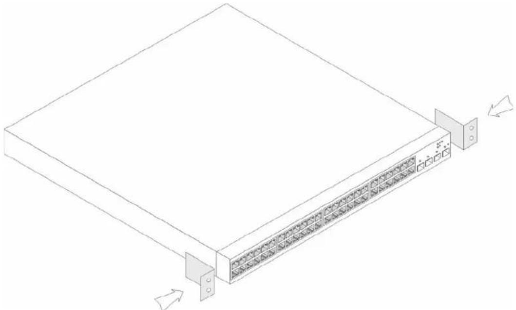
2 Place the supplied wall-mounting bracket on one side of the device, ensuring that the mounting holes on the device line up to the mounting holes on the wall-mounting bracket. The following figure illustrates where to mount the brackets.
Figure 2-2. Bracket Installation for Wall Mounting

natural_image
Isometric line drawing of a network switch or server rack with multiple ports and connectors (no text or symbols)3 Insert the supplied screws into the wall-mounting bracket holes and tighten with a screwdriver.
4 Repeat the process for the wall-mounting bracket on the other side of the device.
5 Place the device on the wall in the location where the device is being installed.
6 On the wall mark the locations where the screws to hold the device must be prepared.
7 On the marked locations, drill the holes and place all plugs (not provided) in the holes.
8 Secure the device to the wall with screws (not provided). Ensure that the ventilation holes are not obstructed.
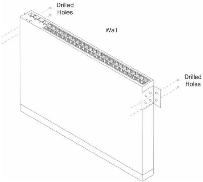
Figure 2-3. Mounting Device on a Wall
Starting and Configuring the Device
After completing all external connections, proceed as follows:
- If the device is to be used as an unmanaged switch, there is no need for a terminal connection.
- A terminal connection is useful if the device is to be used in a managed mode.

NOTE: Before proceeding, read the release notes for this product. The release notes can be downloaded from http://support.dell.com.

NOTE: It is recommended that you obtain the most recent revision of the user documentation from the Dell support website at http://support.dell.com.
Management Modes
The PowerConnect 2808/16/24/48 has a Mode push button on the front panel. The Mode button changes between Managed and Unmanaged modes, or changes from Secure to Managed modes.
Connecting the Device to the Network
To connect to an uplink port, use Category 6 Shielded Twisted-Pair (STP) cables with RJ-45 connectors at both ends. The RJ-45 ports on the Ethernet device support automatic Media-Dependent Interface/Media-Dependent Interface with internal crossover wiring (MDI/MDIX). Standard straight-through twisted-pair cables can be used to connect to any other Ethernet network (systems, servers, switches or routers).

NOTICE: Do not plug a phone jack connector into an RJ-45 port. This will damage the Ethernet device. Use only twisted-pair cables with RJ-45 connectors that conform with FCC standards.
To connect the device to the network:
1 Attach one end of a Twisted-Pair cable to the device's RJ-45 connector and the other end to a switch or server.
2 Make sure each twisted pair cable does not exceed 328 feet (100 meters) in length.
As each connection is made, the link LED corresponding to each port on the device is illuminated (green or amber) indicating that the connection is valid.
Connecting the Terminal to the Device
The device provides an external console port in models 2816/24/48. The console port enables a connection to a terminal desktop system running terminal emulation software for monitoring and configuring the device.
The Console port connector is a male DB-9 connector, implemented as a data terminal equipment (DTE) connector.
To use the Console port, the following is required:
- VT100 compatible terminal or a desktop or portable system with a serial port and running VT100 terminal emulation software.
- An RS-232 null-modem cable with a female DB-9 connector for the Console port and the appropriate connector for the terminal.
To connect a terminal to the device Console port, perform the following:
1 Connect the supplied RS-232 crossover cable to the terminal running VT100 terminal emulation software.
2 Ensure that the terminal emulation software is set as follows:
a Select the appropriate serial port to connect to the console.
b Set the data rate to 9600 baud.
c Set the data format to 8 data bits, 1 stop bit, and no parity.
d Set flow control to none.
e Select VT100 for Emulation mode.
NOTE: When using HyperTerminal with Microsoft® Windows 2000, Windows XP, or Windows Vista, ensure that you have the latest service packs installed. With Windows 2000 Service Pack 2, the arrow keys function properly in HyperTerminal's VT100 emulation. Go to www.microsoft.com for information on Windows 2000, Windows XP, and Windows Vista service packs.
3 Connect the female connector of the RS-232 crossover cable directly to the Console port on the device, and tighten the captive retaining screws. The PowerConnect 2800 series Console port is located on the back panel.
Booting the Device - Managed Mode
The procedure described in this section refers to the device when set to operate as a managed switch. The PowerConnect 2808/16/24/48 models include a built-in dual purpose Mode Button. To change between managed and unmanaged modes, press the Mode Button for less than seven seconds.
Once the device is set to operate as a managed switch the boot procedure can be monitored on the connected terminal as follows:
1 Ensure that the device console port is connected to a VT100 terminal device or VT100 terminal emulator via the device's RS-232 crossover cable.
2 Attach the supplied standard AC power cable to the AC connector on the back panel of the device.
Figure 3-1. Connecting to PowerConnect 2800 Series Console Port
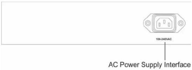
Figure 3-2. Attaching AC Power cable to device
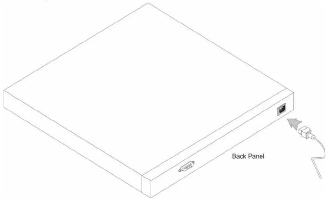
3 Locate an AC power receptacle.
4 Deactivate the AC power receptacle.
5 Connect the device to the AC receptacle.
6 Activate the AC power receptacle.
7 After activating the AC power receptacle, confirm that the device is connected and operating correctly by examining the LEDs on the front panel.
When the power is turned on with the local terminal already connected, the device goes through Power On Self Test (POST). POST runs every time the device is initialized and checks hardware components to determine if the device is fully operational before completely booting. If a critical problem is detected, the program flow stops. If POST passes successfully, a valid executable image is loaded into RAM. POST messages are displayed on the terminal and indicate test success or failure.
The boot process runs less than 45 seconds when in unmanaged mode, and about 90 seconds when in other modes.
Initial Configuration - Managed Mode
The information and procedures described in this section apply to the device when it is configured as a Managed Mode switch.

NOTE: The switch is factory-set by default to Unmanaged Mode.

NOTE: The initial simple configuration uses the following assumptions:
• The PowerConnect device was never configured before, and is in the same state as when it was received.
• The PowerConnect device booted successfully.
- The console connection is established and the console prompt is displayed on the screen of a VT100 terminal device. (Press the
The initial device configuration can be performed via the web management interface, or through the Serial port. After initial configuration, the device can be managed either from the Serial port, or remotely through an interface defined during the initial configuration.
The system prompts you to use the Set-up wizard when the device boots up for the first time in Managed Mode, or if the configuration file is empty because the device is not configured. The Setup Wizard provides guidance through the initial device configuration, and gets the device up and running as quickly as possible.

NOTE: Obtain the following information from your network administrator before configuring the device:
- SNMP Community String and SNMP Management System IP address (optional).
- Username and Password.
- The IP address to be assigned to the VLAN 1 interface through which the device is to be managed (by default, every external and internal port is a member of the VLAN 1)
• The IP subnet mask for the network - The default gateway (next hop router) IP address for configuring the default route.
The Setup Wizard guides you through the initial device configuration, and gets the system up and running as quickly as possible. You can skip using the setup wizard and configure the device manually through the device CLI mode.
The Setup Wizard configures the following fields.
- SNMP Community String and SNMP Management System IP address (optional)
- Username and Password
-
Device IP address
-
IP subnet mask
- Default Gateway IP address
The Setup Wizard displays the following information:
Welcome to Dell Easy Setup Wizard.
The Setup Wizard guides you through the initial switch configuration, and gets you up and running as quickly as possible. You can skip the setup wizard, and enter CLI mode to manually configure the switch.
The system will prompt you with a default answer; by pressing enter, you accept the default. You must respond to the next question to run the setup wizard within 60 seconds, otherwise the system will continue with normal operation using the default system configuration.
Would you like to enter the setup wizard (you must answer this question within 60 seconds)? (Y/N) [Y] Y
NOTE: If you select not to use the Setup Wizard, you can access the Web interface by using the default IP address/mask (192.168.2.1/255.255.255.0).
NOTE: You can exit the Setup Wizard at any time by entering [Ctrl+Z].
Wizard Step 1
The following information displays:
The system is not setup for SNMP management by default.
To manage the switch using SNMP (required for Dell Network Manager) you can:
*Setup the initial SNMP Version 2 account now
*Return later and setup additional SNMP v1/v2 accounts
For more information on setting up SNMP accounts, please see the user documentation.
Would you like to setup the SNMP management interface now? (Y/N) [Y] Y Enter [N] to skip to Step 2.
Enter [Y] to continue the Set-up wizard. The following information displays:
To setup the SNMP management account you must specify the management system IP address and the "community string" or password that the particular management system uses to access the switch. The wizard automatically assigns the highest access level [Privilege Level 15] to this account.
You can use Dell Network Manager or CLI to change this setting, and to add additional management systems. For more information on adding management systems, see the user documentation.
To add a management station:
Please enter the SNMP community string to be used:
[Dell_Network_Manager]
Please enter the IP address of the Management System (A.B.C.D) or wildcard (0.0.0.0) to manage from any Management Station:[0.0.0.0]
Wizard Step 2
The following information displays:
Now we need to setup your initial privilege (Level 15) user account.
This account is used to login to the CLI, Telnet and Web interface.
You may setup other accounts and change privilege levels later.
For more information on setting up user accounts and changing privilege levels, see the user documentation.
To setup a user account:
Enter the user name<1-20>: admin
Please enter the user password:*****
Please reenter the user password:*****
Wizard Step 3
The following information displays:
Next, an IP address is setup.
The IP address is defined on the default VLAN, (VLAN #1). This is the IP address you use to access the Telnet, Web interface, or SNMP interface for the switch. To setup an IP address:
Please enter the IP address of the device (A.B.C.D):10.6.22.100
Please enter the IP subnet mask (A.B.C.D or nn): [255.255.255.224]
Wizard Step 4
The following information displays:
Finally, setup the default gateway.
Please enter the IP address of the gateway from which this network is reachable(e.g. 192.168.1.1).Default gateway (A.B.C.D):[10.6.22.97]
Enter the default gateway.
Press Enter. The following is displayed (as per the example parameters described):
This is the configuration information that has been collected:
SNMP Interface = Dell_Network_Manager@0.0.0.0
User Account setup = admin
Password = *****
Management IP address = 10.6.22.100 255.255.255.224
Default Gateway is 10.6.22.97
Wizard Step 5
The following information displays:
If the information is correct, please select (Y) to save the configuration, and copy to the start-up configuration file. If the information is incorrect, select (N) to discard configuration and restart the wizard: (Y/N)[Y] Y
Configuring SNMP management interface.
Configuring user account.....
Configuring IP and subnet.....
Thank you for using Dell Easy Setup Wizard.
Web Configuration
The web management interface is used to configure and manage the device when it is in Managed mode. To use the web management interface, you must first login.
1 Enter the device IP address in the web browser address bar and press
2 Enter a username and password and click
The IP Addressing page contains a link to the IP Interface Parameters page that is used to assign the device IP address, subnet mask and default gateway, and for enabling or disabling DIICP.
1 In the web management interface navigation menu at left, select the System > IP Addressing > IP Interface Parameters screen.
Figure 3-3. Web management IP Interface Parameters

2 Enter the IP Address, Subnet Mask and Default Gateway.
3 Click Apply Changes. The device is configured.
The Newly Introduced Eco-Friendly Feature: Green Ethernet
The Green Ethernet feature improves network energy consumption. The Green Ethernet power saving technology automatically reduces power consumption upon detection of a Link Down and/or a Short Reach, ensuring that networks use less power per port and are more eco-friendly, without giving up network integrity.
The Energy-Detection and Short-Reach modes are enabled by default.
Regulatory Notices
For additional regulatory information, see the Regulatory Compliance Homepage on www.dell.com at the following location: www.dell.com/regulatory_compliance.
Round Rock, TX 78682
Avenida Soles No. 55
natural_image
Isometric line drawing of a server rack with connectors and ventilation slots (no text or symbols)natural_image
Isometric line drawing of a server rack with multiple Ethernet ports and mounting brackets (no text or symbols)Welcome to Dell Easy Setup Wizard.
The Setup Wizard guides you through the initial switch configuration, and gets you up and running as quickly as possible. You can skip the setup wizard, and enter CLI mode to manually configure the switch. The system will prompt you with a default answer; by pressing enter, you accept the default. You must respond to the next question to run the setup wizard within 60 seconds, otherwise the system will continue with normal operation using the default system
Would you like to enter the setup wizard (you must answer this question within 60 seconds)? (Y/N) [Y] Y
The system is not setup for SNMP management by default.
To manage the switch using SNMP (required for Dell Network Manager) you can:
*Setup the initial SNMP Version 2 account now
*Return later and setup additional SNMP v1/v2 accounts
For more information on setting up SNMP accounts, please see the userdocumentation.
Would you like to setup the SNMP management interface now? (Y/N) [Y] Y
To setup the SNMP management account you must specify the managementsystem IP address and the "community string" or password that theparticular management system uses to access the switch. The wizardautomatically assigns the highest access level [Privilege Level 15] to this account.
You can use Dell Network Manager or CLI to change this setting, and to add additional management systems. For more information on adding management systems, see the user documentation.
To add a management station:
Please enter the SNMP community string to be used: [Dell_Network_Manager]
Now we need to setup your initial privilege (Level 15) user account.
This account is used to login to the CLI, Telnet and Web interface.
You may setup other accounts and change privilege levels later.
For more information on setting up user accounts and changingprivilege levels,see the user documentation.
To setup a user account:
Enter the user name<1-20>: admin
Please enter the user password:*****
Please reenter the user password:*****
Next, an IP address is setup.
The IP address is defined on the default VLAN,(VLAN #2). This is theIP address you use to access the Telnet, Web interface, or SNMPinterface for the switch. To setup an IP address:
Please enter the IP address of the device (A.B.C.D):10.6.22.100
Please enter the IP subnet mask (A.B.C.D or nn): [255.255.255.224]
Finally, setup the default gateway.
Please enter the IP address of the gateway from which this network is reachable (e.g. 192.168.1.1). Default gateway (A.B.C.D): [10.6.22.97]
This is the configuration information that has been collected:
SNMP Interface = Dell_Network_Manager@0.0.0.0
User Account setup = admin
Password = *****
Management IP address = 10.6.22.100 255.255.255.224
Default Gateway is 10.6.22.97
If the information is correct, please select (Y) to save the configuration, and copy to the start-up configuration file. If the information is incorrect, select (N) to discard configuration and restart the wizard: (Y/N)[Y] Y
Configuring SNMP management interface.
Configuring user account.....
Configuring IP and subnet.....
Thank you for using Dell Easy Setup Wizard.
Avenida Soles No. 55
natural_image
Isometric line drawing of a server rack with connectors and ports (no text or symbols)natural_image
Isometric line drawing of a network switch or server rack with multiple ports and connectors (no text or symbols)Would you like to setup the SNMP management interface now?
Round Rock, TX 78682
Avenida Soles No. 55
natural_image
Isometric line drawing of a server rack with ports and connectors (no text or symbols)natural_image
Isometric line drawing of a server rack with multiple Ethernet ports and mounting brackets (no text or symbols)Welcome to Dell Easy Setup Wizard.
The Setup Wizard guides you through the initial switch configuration, and gets you up and running as quickly as possible. You can skip the setup wizard, and enter CLI mode to manually configure the switch. The system will prompt you with a default answer; by pressing enter, you accept the default. You must respond to the next question to run the setup wizard within 60 seconds, otherwise the system will continue with normal operation using the default system configuration.
Would you like to enter the Setup Wizard. (you must answer this question within 60 seconds) ? (Y/N) [Y] Y
The system is not setup for SNMP management by default.
To manage the switch using SNMP (required for Dell Network Manager) you can:
*Setup the initial SNMP version 2 account now
*Return later and setup additional SNMP v1/v3 accounts
For more information on setting up SNMP accounts, please see the user documentation.
Would you like to setup the SNMP management interface now? (Y/N) [Y] Y
To setup the SNMP management account you must specify the management system IP address and the "community string" or password that the particular management system uses to access the switch. The wizard automatically assigns the highest access level [Privilege Level 15] to this account.
You can use Dell Network Manager or CLI to change this setting, and to add additional management systems. For more information on adding management systems, see the user documentation.
To add a management station:
Please enter the SNMP community string to be used [Dell_Network_Manager]
Now we need to setup your initial privilege (Level 15) user account.
This account is used to login to the CLI, Telnet and Web interface.
You may setup other accounts and change privilege levels later
For more information on setting up user accounts and changing privilege levels, see the user documentation.
To setup a user account:
Enter the user name<1-20>: admin
Please enter the user password:*****
Please reenter the user password: *****
Next, an IP address is setup.
The IP address is defined on the default VLAN, (VLAN #2). This is the IP address you use to access the Telnet, Web interface, or SNMP interface for the switch. To setup an IP address:
Please enter the IP address of the device (A.B.C.D): 10.6.22.100
Please enter the IP subnet mask (A.B.C.D or nn): [255.255.255.224]
Finally, setup the default gateway.
Please enter the IP address of the gateway from which this network is reachable (e.g. 192.168.1.1).Default gateway (A.B.C.D): [10.6.22.97]
This is the configuration information that has been collected:
Interface SNMP = Dell_Network_Manager@0.0.0.0
User Account setup = admin
Password = *****
Management IP address = 10.6.22.100 255.255.255.224
Default Gateway is 10.6.22.97
If the information is correct, please select (Y) to save the configuration, and copy to the start-up configuration file. If the information is incorrect, select (N) to discard configuration and restart the wizard: (Y/N)[Y]Y
Configuring SNMP management interface.
Configuring user account.....
Configuring IP and subnet.....
Thank you for using Dell Easy Setup Wizard.
Round Rock, TX 78682
Avenida Soles No. 55
If the information is correct, please select (Y) to save the configuration, and copy to the start-up configuration file. If the information is incorrect, select (N) to discard configuration and restart the wizard: (Y/N)[Y] Y
Configuring SNMP management interface.
Configuring user account.....
Configuring IP and subnet.....
Thank you for using Dell Easy Setup Wizard.
Finally, setup the default gateway.
Please enter the IP address of the gateway from which this network is reachable(e.g. 192.168.1.1).Default gateway (A.B.C.D): [10.6.22.97]
This is the configuration information that has been collected:
SNMP Interface = Dell_Network_Manager@0.0.0.0
User Account setup = admin
Password = *****
Management IP address255.255.255.224 10.6.22.100 =
Default Gateway is 10.6.22.97
Now we need to setup your initial privilege (Level 15) user account.
This account is used to login to the CLI, Telnet and Web interface.
You may setup other accounts and change privilege levels later.
For more information on setting up user accounts and changing privilege levels, see the user documentation.
To setup a user account:
admin: Enter the user name<1-20>
Please enter the user password:*****
Please reenter the user password:*****
Next, an IP address is setup.
The IP address is defined on the default VLAN, (VLAN #2). This is the IP address you use to access the Telnet, Web interface, or SNMP interface for the switch. To setup an IP address:
10.6.22.100: Please enter the IP address of the device (A.B.C.D)
[255.255.255.224]: Please enter the IP subnet mask (A.B.C.D or nn)
To setup the SNMP management account you must specify the management system IP address and the "community string" or password that the particular management system uses to access the switch. The wizard automatically assigns the highest access level [Privilege Level 15] to this account.
You can use Dell Network Manager or CLI to change this setting, and to add additional management systems. For more information on adding management systems, see the user documentation.
To add a management station:
Please enter the SNMP community string to be used:
[Dell_Network_Manager]
Welcome to Dell Easy Setup Wizard.
The Setup Wizard guides you through the initial switch configuration, and gets you up and running as quickly as possible. You can skip the setup wizard, and enter CLI mode to manually configure the switch. The system will prompt you with a default answer; by pressing enter, you accept the default. You must respond to the next question to run the setup wizard within 60 seconds, otherwise the system will continue with normal operation using the default system configuration.
Would you like to enter the setup wizard (you must answer this question within 60 seconds)? (Y/N)[Y] Y
The system is not setup for SNMP management by default.
To manage the switch using SNMP (required for Dell Network Manager) you can:
*Setup the initial SNMP Version 2 account now
*Return later and setup additional SNMP v1/v2 accounts
For more information on setting up SNMP accounts, please see the user documentation.
Would you like to setup the SNMP management interface now? Y [N] (N/Y)
PowerConnect 2808/16/24/48.
: RS-232, VT100, VT100
.הכלה 2
PowerConnect 2808/16/24/48
natural_image
Line drawing of a rectangular electronic device with an attached port and cable, labeled 'NPK NO' (no other text or symbols)3 LED -הכלהה-הכלהה-הכלהה-הכלהה-הכלהה-הכלהה-הכלהה-הכלהה-הכלהה-הכלהה-הכלהה-הכלהה-הכלהה-הכלהה-הכלהה-הכלהה-הכלהה-הכלהה-הכלהה-הכלהה-הכלהה
natural_image
Isometric line drawing of a server rack with multiple ports and connectors, showing internal structure and mounting points (no text or symbols)natural_image
Isometric line drawing of a server rack with connectors and ventilation slots (no text or symbols)PowerConnect 2808/16/24/48
•
•
•
PowerConnect 2808/16/24/48
116
natural_image
Isometric line drawing of a server rack with ports and connectors (no text or symbols)2 Pasang baut yang telah disediakan ke lubang pemasangan rak dan kencangkan dengan obeng.
natural_image
Isometric line drawing of a server rack with multiple Ethernet ports and mounting brackets (no text or symbols)Welcome to Dell Easy Setup Wizard.
The Setup Wizard guides you through the initial switch configuration, and gets you up and running as quickly as possible. You can skip the setup wizard, and enter CLI mode to manually configure the switch. The system will prompt you with a default answer; by pressing enter, you accept the default. You must respond to the next question to run the setup wizard within 60 seconds, otherwise the system will continue with normal operation using the default system configuration.
Would you like to enter the setup wizard (you must answer this question within 60 seconds)? (Y/N) [Y] Y
The system is not setup for SNMP management by default.
To manage the switch using SNMP (required for Dell Network Manager) you can:
*Setup the initial SNMP Version 2 account now
*Return later and setup additional SNMP v1/v2 accounts
For more information on setting up SNMP accounts, please see the user documentation.
Would you like to setup the SNMP management interface now? (Y/N) [Y] Y
To setup the SNMP management account you must specify the management system IP address and the "community string" or password that the particular management system uses to access the switch. The wizard automatically assigns the highest access level [Privilege Level 15] to this account.
You can use Dell Network Manager or CLI to change this setting, and to add additional management systems. For more information on adding management systems, see the user documentation.
To add a management station:
Please enter the SNMP community string to be used:
[Dell_Network_Manager]
Now we need to setup your initial privilege (Level 15) user account.
This account is used to login to the CLI, Telnet and Web interface.
You may setup other accounts and change privilege levels later.
For more information on setting up user accounts and changing privilege levels, see the user documentation.
To setup a user account:
Enter the user name<1-20>: admin
Please enter the user password:*****
Please reenter the user password:*****
Next, an IP address is setup.
The IP address is defined on the default VLAN, (VLAN #2). This is the IP address you use to access the Telnet, Web interface, or SNMP interface for the switch. To setup an IP address:
Please enter the IP address of the device (A.B.C.D):10.6.22.100
Please enter the IP subnet mask (A.B.C.D or nn): [255.255.255.224]
(Kemudian, alamat IP diatur.
Finally, setup the default gateway.
Please enter the IP address of the gateway from which this network is reachable(e.g. 192.168.1.1).Default gateway (A.B.C.D): [10.6.22.97]
(Terakhir, atur default gateway.
Masukkan default gateway.
This is the configuration information that has been collected:
SNMP Interface = Dell_Network_Manager@0.0.0.0
User Account setup = admin
Password = *****
Management IP address = 10.6.22.100 255.255.255.224
Default Gateway is 10.6.22.97
If the information is correct, please select (Y) to save the configuration, and copy to the start-up configuration file. If the information is incorrect, select (N) to discard configuration and restart the wizard: (Y/N)[Y] Y
Configuring SNMP management interface.
Configuring user account.....
Configuring IP and subnet.....
Thank you for using Dell Easy Setup Wizard.
Round Rock, TX 78682
Avenida Soles No. 55
natural_image
Isometric line drawing of a server rack with connectors and ports, no text or symbols presentnatural_image
Isometric line drawing of a server rack with multiple Ethernet ports and mounting brackets (no text or symbols)將裝置連接至電源供給設備
Welcome to Dell Easy Setup Wizard.
The Setup Wizard guides you through the initial switch configuration, and gets you up and running as quickly as possible. You can skip the setup wizard, and enter CLI mode to manually configure the switch. The system will prompt you with a default answer; by pressing enter, you accept the default. You must respond to the next question to run the setup wizard within 60 seconds, otherwise the system will continue with normal operation using the default system configuration.
Would you like to enter the setup wizard (you must answer this question within 60 seconds)? (Y/N)[Y] Y
(歡迎至 Dell 簡易安裝靈。
The system is not setup for SNMP management by default.
To manage the switch using SNMP (required for Dell Network Manager) you can:
*Setup the initial SNMP Version 2 account now
*Return later and setup additional SNMP v1/v2 accounts
For more information on setting up SNMP accounts, please see the user documentation.
Would you like to setup the SNMP management interface now? (Y/N)[Y] Y
(此系統非預設為 SNMP 管理。
To setup the SNMP management account you must specify the management system IP address and the "community string" or password that the particular management system uses to access the switch. The wizard automatically assigns the highest access level [Privilege Level 15] to this account.
You can use Dell Network Manager or CLI to change this setting, and to add additional management systems. For more information on adding management systems, see the user documentation.
To add a management station:
Please enter the SNMP community string to be used: [Dell_Network_Manager]
Now we need to setup your initial privilege (Level 15) user account.
This account is used to login to the CLI, Telnet and Web interface.
You may setup other accounts and change privilege levels later.
For more information on setting up user accounts and changing privilege levels, see the user documentation.
To setup a user account:
Enter the user name<1-20>: admin
Please enter the user password:*****
Please reenter the user password:*****
Next, an IP address is setup.
The IP address is defined on the default VLAN, (VLAN #2). This is the IP address you use to access the Telnet, Web interface, or SNMP interface for the switch. To setup an IP address:
Please enter the IP address of the device (A.B.C.D):10.6.22.100
Please enter the IP subnet mask (A.B.C.D or nn): [255.255.255.224]
(下一步,設定 IP 位址。
Finally, setup the default gateway.
Please enter the IP address of the gateway from which this network is reachable(e.g. 192.168.1.1).Default gateway (A.B.C.D):[10.6.22.97]
(最後,設定預設閘道。
This is the configuration information that has been collected: (這是已收集的組態資訊:)
SNMP Interface = Dell_Network_Manager@0.0.0.0
(SNMP 介面 = Dell_Network_Manager@0.0.0.0)
User Account setup = admin (使用者帳戶設定 = admin)
Password = ***** ( 密碼 = *****)
Management IP address = 10.6.22.100 255.255.255.224
If the information is correct, please select (Y) to save the configuration, and copy to the start-up configuration file. If the information is incorrect, select (N) to discard configuration and restart the wizard: (Y/N)[Y] Y
Configuring SNMP management interface.
Configuring user account.....
Configuring IP and subnet.....
Thank you for using Dell Easy Setup Wizard.
Round Rock, TX 78682
Avenida Soles No. 55
natural_image
Isometric line drawing of a server rack with connectors and ventilation slots (no text or symbols)natural_image
Isometric line drawing of a server rack with multiple Ethernet ports and mounting brackets (no text or symbols)Welcome to Dell Easy Setup Wizard.
The Setup Wizard guides you through the initial switch configuration, and gets you up and running as quickly as possible. You can skip the setup wizard, and enter CLI mode to manually configure the switch. The system will prompt you with a default answer; by pressing enter, you accept the default. You must respond to the next question to run the setup wizard within 60 seconds, otherwise the system will continue with normal operation using the default system configuration.
Would you like to enter the setup wizard (you must answer this question within 60 seconds)? (Y/N) [Y] Y
(欢迎使用 Dell 轻松安装向导。
The system is not setup for SNMP management by default.
To manage the switch using SNMP (required for Dell Network Manager) you can:
*Setup the initial SNMP Version 2 account now
*Return later and setup additional SNMP v1/v2 accounts
For more information on setting up SNMP accounts, please see the user documentation.
Would you like to setup the SNMP management interface now? (Y/N)[Y] Y
To setup the SNMP management account you must specify the management system IP address and the "community string" or password that the particular management system uses to access the switch. The wizard automatically assigns the highest access level [Privilege Level 15] to this account.
You can use Dell Network Manager or CLI to change this setting, and to add additional management systems. For more information on adding management systems, see the user documentation.
To add a management station:
Please enter the SNMP community string to be used: [Dell_Network_Manager]
Now we need to setup your initial privilege (Level 15) user account.
This account is used to login to the CLI, Telnet and Web interface.
You may setup other accounts and change privilege levels later.
For more information on setting up user accounts and changing privilege levels, see the user documentation.
To setup a user account:
Enter the user name<1-20>: admin
Please enter the user password:*****
Please reenter the user password:*****
Next, an IP address is setup.
The IP address is defined on the default VLAN, (VLAN #2). This is the IP address you use to access the Telnet, Web interface, or SNMP interface for the switch. To setup an IP address:
Please enter the IP address of the device (A.B.C.D):10.6.22.100
Please enter the IP subnet mask (A.B.C.D or nn): [255.255.255.224]
( 设置下一个 IP 地址。
Finally, setup the default gateway.
Please enter the IP address of the gateway from which this network is reachable(e.g. 192.168.1.1).Default gateway (A.B.C.D):[10.6.22.97]
( 最后设置默认网关。
This is the configuration information that has been collected:
(这是已收集到的配置信息:)
SNMP Interface = Dell_Network_Manager@0.0.0.0
User Account setup = admin
Password = *****
Management IP address = 10.6.22.100 255.255.255.224
Default Gateway is 10.6.22.97
(SNMP 接口 = Dell_Network_Manager@0.0.0.0
用户帐户设置 = admin
If the information is correct, please select (Y) to save the configuration, and copy to the start-up configuration file. If the information is incorrect, select (N) to discard configuration and restart the wizard: (Y/N)[Y] Y
Configuring SNMP management interface.
Configuring user account.....
Configuring IP and subnet.....
Thank you for using Dell Easy Setup Wizard.
Round Rock, TX 78682
Importador:
Dell M 亢ico, S.A. de C.V.
Avenida Soles No. 55
natural_image
Isometric line drawing of a server rack with ports and connectors (no text or symbols)natural_image
Isometric line drawing of a server rack with multiple Ethernet connectors and mounting brackets (no text or symbols)전원 공급 장치에 장치 연결하기
Welcome to Dell Easy Setup Wizard.
The Setup Wizard guides you through the initial switch configuration, and gets you up and running as quickly as possible. You can skip the setup wizard, and enter CLI mode to manually configure the switch. The system will prompt you with a default answer; by pressing enter, you accept the default. You must respond to the next question to run the setup wizard within 60 seconds, otherwise the system will continue with normal operation using the default system configuration.
The system is not setup for SNMP management by default.
To manage the switch using SNMP (required for Dell Network Manager) you can:
*Setup the initial SNMP Version 2 account now
*Return later and setup additional SNMP v1/v2 accounts
For more information on setting up SNMP accounts, please see the user documentation.
To setup the SNMP management account you must specify the management system IP address and the "community string" or password that the particular management system uses to access the switch. The wizard automatically assigns the highest access level [Privilege Level 15] to this account.
You can use Dell Network Manager or CLI to change this setting, and to add additional management systems. For more information on adding management systems, see the user documentation.
To add a management station:
Please enter the SNMP community string to be used:
Now we need to setup your initial privilege (Level 15) user account.
This account is used to login to the CLI, Telnet and Web interface.
You may setup other accounts and change privilege levels later.
For more information on setting up user accounts and changing privilege levels, see the user documentation.
To setup a user account:
Enter the user name<1-20>: admin
Please enter the user password:*****
Next, an IP address is setup.
The IP address is defined on the default VLAN, (VLAN #2). This is the IP address you use to access the Telnet, Web interface, or SNMP interface for the switch. To setup an IP address:
Please enter the IP address of the device (A.B.C.D):10.6.22.100
Finally, setup the default gateway.
This is the configuration information that has been collected:
User Account setup = admin
Password = *****
Management IP address = 10.6.22.100 255.255.255.224
Default Gateway is 10.6.22.97
마법사 5 단계
다음 정보가 표시됩니다:
If the information is correct, please select (Y) to save the configuration, and copy to the start-up configuration file. If the information is incorrect, select (N) to discard configuration and restart the wizard: (Y/N)[Y] Y
Configuring SNMP management interface.
Configuring user account.....
Configuring IP and subnet.....
www.dell.com/regulatory_compliance.
Round Rock, TX 78682
Avenida Soles No. 55
natural_image
Isometric line drawing of a server rack with connectors and ventilation slots (no text or symbols)natural_image
Isometric line drawing of a server rack with multiple ports and connectors (no text or symbols)Welcome to Dell Easy Setup Wizard
The Setup Wizard guides you through the initial switch configuration, and gets you up and running as quickly as possible. You can skip the setup wizard, and enter CLI mode to manually configure the switch. The system will prompt you with a default answer; by pressing enter, you accept the default. You must respond to the next question to run the setup wizard within 60 seconds, otherwise the system will continue with normal operation using the default system configuration.
To setup the SNMP management account you must specify the management system IP address and the "community string" or password that the particular management system uses to access the switch. The wizard automatically assigns the highest access level [Privilege Level 15] to this account.
You can use Dell Network Manager or CLI to change this setting, and to add additional management systems. For more information on adding management systems, see the user documentation.
The IP address is defined on the default VLAN, (VLAN #2). This is the IP address you use to access the Telnet, Web interface, or SNMP interface for the switch. To setup an IP address:
This is the configuration information that has been collected: (収集された設定情報:)
SNMP Interface = Dell_Network_Manager@0.0.0.0
User Account setup = admin
Password = *****
Management IP address = 10.6.22.100 255.255.255.224
Default Gateway is 10.6.22.97
ウィザード手順5
次の情報が表示されます。
If the information is correct, please select (Y) to save the configuration, and copy to the start-up configuration file. If the information is incorrect, select (N) to discard configuration and restart the wizard: (Y/N) [Y]Y
Avenida Soles No. 55
natural_image
Isometric line drawing of a server rack with connectors and ventilation slots (no text or symbols)natural_image
Isometric line drawing of a server rack with multiple Ethernet ports and mounting brackets (no text or symbols)Welcome to Dell Easy Setup Wizard.
The Setup Wizard guides you through the initial switch configuration, and gets you up and running as quickly as possible. You can skip the setup wizard, and enter CLI mode to manually configure the switch. The system will prompt you with a default answer; by pressing enter, you accept the default. You must respond to the next question to run the setup wizard within 60 seconds, otherwise the system will continue with normal operation using the default system configuration.
Would you like to enter the setup wizard (you must answer this question within 60 seconds)? (Y/N)[Y] Y
The system is not setup for SNMP management by default.
To manage the switch using SNMP (required for Dell Network Manager) you can:
*Setup the initial SNMP Version 2 account now
*Return later and setup additional SNMP v1/v2 accounts
For more information on setting up SNMP accounts, please see the user documentation.
Would you like to setup the SNMP management interface now? (Y/N)[Y] Y
To setup the SNMP management account you must specify the management system IP address and the "community string" or password that the particular management system uses to access the switch. The wizard automatically assigns the highest access level [Privilege Level 15] to this account.
You can use Dell Network Manager or CLI to change this setting, and to add additional management systems. For more information on adding management systems, see the user documentation.
To add a management station:
Please enter the SNMP community string to be used: [Dell_Network_Manager]
Now we need to setup your initial privilege (Level 15) user account.
This account is used to login to the CLI, Telnet and Web interface.
You may setup other accounts and change privilege levels later.
For more information on setting up user accounts and changing privilege levels, see the user documentation.
To setup a user account:
Enter the user name<1-20>: admin
Please enter the user password:*****
Please reenter the user password:*****
Next, an IP address is setup.
The IP address is defined on the default VLAN, (VLAN #2). This is the IP address you use to access the Telnet, Web interface, or SNMP interface for the switch. To setup an IP address:
Please enter the IP address of the device (A.B.C.D):10.6.22.100
Please enter the IP subnet mask (A.B.C.D or nn): [255.255.255.224]
Finally, setup the default gateway.
Please enter the IP address of the gateway from which this network is reachable(e.g. 192.168.1.1).Default gateway (A.B.C.D):[10.6.22.97]
This is the configuration information that has been collected:
SNMP Interface = Dell_Network_Manager@0.0.0.0
User Account setup = admin
Password = *****
Management IP address = 10.6.22.100 255.255.255.224
Default Gateway is 10.6.22.97
If the information is correct, please select (Y) to save the configuration, and copy to the start-up configuration file. If the information is incorrect, select (N) to discard configuration and restart the wizard: (Y/N)[Y] Y
Configuring SNMP management interface.
Configuring user account.....
Configuring IP and subnet.....
Thank you for using Dell Easy Setup Wizard.
Round Rock, TX 78682
Avenida Soles No. 55
Printed on Recycled Paper
www.dell.com | support.dell.com

- Notes, Notices, and Cautions
- Contents
- Installation
- Mounting the Device
- Starting and Configuring the Device
- Site Preparation
- Site Requirements
- Unpacking
- Package Contents
- Unpacking the Device
- Mounting the Device
- Overview
- Installation Precautions
- Device Rack Installation
- Installing on a Flat Surface
- Installing on a Wall
- Starting and Configuring the Device
- Management Modes
- Connecting the Device to the Network
- Connecting the Terminal to the Device
- Booting the Device - Managed Mode
- Initial Configuration - Managed Mode
- Wizard Step 1
- Wizard Step 2
- Wizard Step 3
- Wizard Step 4
- Wizard Step 5
- Web Configuration
- The Newly Introduced Eco-Friendly Feature: Green Ethernet
- Regulatory Notices
- 將裝置連接至電源供給設備
- 전원 공급 장치에 장치 연결하기
- 마법사 5 단계
- ウィザード手順5
Brand : DELL
Model : PowerConnect 2808
Category : Network card / adapter