
PowerConnect W3200 - Controller DELL - Free user manual and instructions
Find the device manual for free PowerConnect W3200 DELL in PDF.
| Product type | Wireless Local Area Network Controller (WLAN Controller) |
| Brand | Dell |
| Model | PowerConnect W3200 |
| Dimensions (H x W x D) | 44 x 351 x 297 mm (without mounting brackets) |
| Weight | 3.2 kg (with mounting brackets) |
| Power input | 90–264 V AC, 1.5 A, 47–63 Hz |
| Power consumption | 35 W maximum |
| Operating temperature | 0 to 40 °C |
| Operating humidity | 5 to 95% non-condensing |
| Maximum access point capacity | 32 |
| Network ports | 4 dual-purpose ports 1000Base-X (SFP) or 10/100/1000Base-T |
| Dedicated SFP ports | 4 ports 1000Base-X (SFP) |
| Gigabit copper ports | 4 ports 10/100/1000Base-T (RJ-45) |
| Serial console port | RJ-45 |
| Status indicators | POWER, STATUS, LNK/ACT (per port), speed (1000) |
| Mounting | 19-inch rack (Telecom or server) or tabletop |
| Required software | ArubaOS 5.0.2 or later |
| Compliance | FCC Class A, Canada NMB-003, RoHS |
| Laser safety | Class 1 (with approved SFP modules) |
| Optional accessories | SFP modules (mini-GBIC) sold separately |
| Maintenance and cleaning | Disconnect before cleaning; use a dry, lint-free cloth |
| Spare parts and repairability | Contact Dell for parts and repairs |
Frequently Asked Questions - PowerConnect W3200 DELL
User questions about PowerConnect W3200 DELL
0 question about this device. Answer the ones you know or ask your own.
Ask a new question about this device
Download the instructions for your Controller in PDF format for free! Find your manual PowerConnect W3200 - DELL and take your electronic device back in hand. On this page are published all the documents necessary for the use of your device. PowerConnect W3200 by DELL.
USER MANUAL PowerConnect W3200 DELL
Dell PowerConnect W-3000 Series Controllers
Installation Guide
Copyright
© 2010 Aruba Networks, Inc. AirWave®, Aruba Networks®, Aruba Mobility Management System®, and other registered marks are trademarks of Aruba Networks, Inc. Dell™, the DELL™ logo, and PowerConnect™ are trademarks of Dell Inc.
All rights reserved. Specifications in this manual are subject to change without notice.
Originated in the USA. Any other trademarks appearing in this manual are the property of their respective companies.
Open Source Code
Certain Aruba products include Open Source software code developed by third parties, including software code subject to the GNU General Public License (GPL), GNU Lesser General Public License (LGPL), or other Open Source Licenses. The Open Source code used can be found at this site:
http://www.arubanetworks.com/open_source
Legal Notice
The use of Aruba Networks, Inc. switching platforms and software, by all individuals or corporations, to terminate other vendors' VPN client devices constitutes complete acceptance of liability by that individual or corporation for this action and indemnifies, in full, Aruba Networks, Inc. from any and all legal actions that might be taken against it with respect to infringement of copyright on behalf of those vendors.
Contents
About This Guide....5
Guide Overview....5
Related Documents....5
Contacting Dell....5
Chapter 1 About the PowerConnect W-3000 Series Controllers....7
Minimum Software Requirements....7
Package Checklist....7
Model Overview....8
1000Base-X (SFP) Ports 8
10/100/1000Base-T Gigabit Ethernet Ports 9
Serial Console Port....9
Serial Console Port Adaptor 9
AC Power Socket....10
LED Status Indicators 10
Chapter 2 Installing the W-3000 Series Controllers ....13
For a Telecom Rack:....13
For a Server Rack: 13
Installation in a Telecom Rack....13
Installation in a Server Rack....14
Tabletop Deployment....15
Initial Setup and Network Connectivity 15
Removal....15
Appendix A Specifications, Safety & Compliance 17
Physical Specifications 17
Power Management Specifications....17
Power Consumption....17
Power Specifications (AC Input Requirements) 17
Operating Specifications....17
Storage Specifications 18
Safety and Regulatory Compliance 18
FCC Class A Device 18
Proper Disposal of Dell Equipment....18
European Union RoHS 18
This preface includes the following information:
• “Guide Overview” on page 5
• “Related Documents” on page 5
- “Contacting Dell” on page 5
Guide Overview
- Chapter 1, “About the PowerConnect W-3000 Series Controllers” on page 7 provides a detailed hardware overview of the three controllers within the W-3000 Series Controllers: the W-3200, the W-3400, and the W-3600.
- Chapter 2, “Installing the W-3000 Series Controllers” on page 13 provides rack mounting and installation instructions.
- Appendix A, “Specifications, Safety & Compliance” on page 17 includes product technical specifications and safety and regulatory compliance information.
Related Documents
The following documents are referred to in this guide and are considered components of the complete documentation set needed for successful installation and management of a Dell Controller:
• Dell PowerConnect ArubaOS Quick Start Guide
• Dell PowerConnect ArubaOS User Guide
• Dell PowerConnect ArubaOS 5.0 Command Line Reference
Contacting Dell
| Web Site Support | |
| Main Site www.dell.com | |
| Support Site support.dell.com | |
| Dell Documentation support.dell.com/manuals | |
The PowerConnect W-3000 Series Controllers consists of three enterprise-class, wireless LAN controllers. These controllers connect, control, and intelligently integrate wireless Access Points (APs) and Air Monitors (AMs) into a wired LAN system.
The PowerConnect W-3000 Series Controllers consists of the following models:
• W-3200 Multi-Service Controller
The W-3200 is capable of supporting up to 32 campus connected APs..
• W-3400 Multi-Service Controller
The W-3400 is capable of supporting up to 64 campus connected APs.
• W-3600 Multi-Service Controller
The W-3600 is capable of supporting up to 128 campus connected APs.

Note: Feature related AP licenses are counted independently and in addition to the AP upgrade licenses. Contact your Dell representative for complete details regarding software licensing options and support capacity.
Minimum Software Requirements
The W-3000 Series Controllers require ArubaOS 5.0.2 or later.
Note: The master controller, its redundant master controller, and all of its local controllers must run on the same ArubaOS version. Once you upgrade your network and install the W-3000 Series Controllers into your network, verify that the software version on your controller matches the rest of the network. If the version shipped on the controller is prior to the version that you upgraded your network to, you must upgrade the code on the controller to match the rest of the network.

Package Checklist
• W-3000 Series Controllers
• AC Power Cord (country-specific)
- Rack Mount Brackets with Hardware (for rack mounting)
• Flat Serial Cable (RJ-45)
• Rubber Feet (for table top deployments)
- Serial Console Port Adaptor (RJ-45 to DB9)
• Dell PowerConnect ArubaOS Quick Start Guide
• End User License Agreement (EULA)
• Safety, Environmental, and Regulatory Information (SERI) document
• Warranty and Support Information (WSI) document

Note: Inform your supplier if there are any incorrect, missing, or damaged parts. If possible, retain the carton, including the original packing materials. Use these materials to repack and return the unit to the supplier if needed.

Note: Optional accessories, such as SFP modules, are available for use with the W-3000 Series Controllers and are sold separately. Contact your Dell representative for details and assistance.
Model Overview
The physical hardware model overview of the W-3000 Series Controllers covers all three models within the series. The difference between the three controller models is dependent on the licensing level purchased. The controller model depicted in the illustrations throughout this chapter is the W-3200.
Figure 1 W-3200 Front View
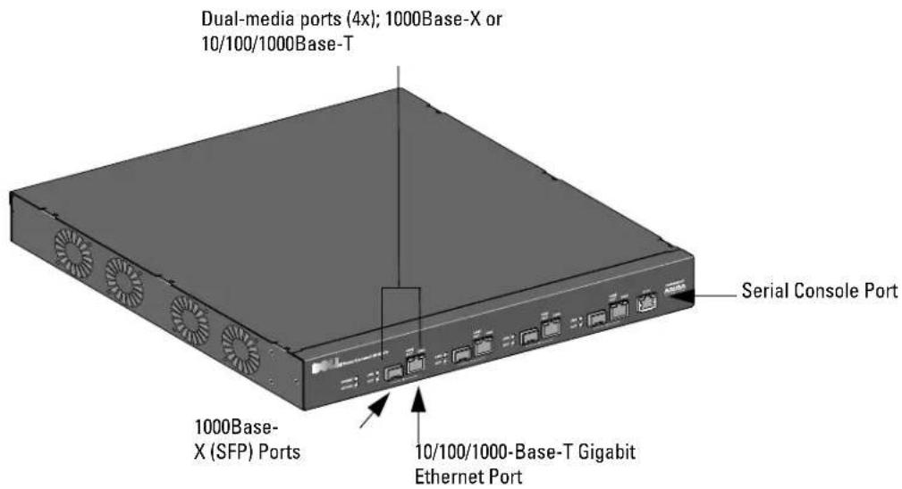

Note: Ports zero through three are dual-media ports and can utilize either the 1000Base-X or 10/100/1000Base-T connections provided. However, the 1000Base-X fiber connection has priority over the 10/100/1000Base-T copper connection. If a link is detected for the 1000Base-X interface, the 10/100/1000Base-T connection will be disabled.
1000Base-X (SFP) Ports
There are four 1000Base-X combination ports for fiber connectivity only and are intended for use with Dell SFPs (mini-CBICs).
To purchase compatible SFP modules, contact your Dell representative for details and assistance.

Note: Dell tests and supports Dell optics within their controller systems. Third party optics are not tested or supported; therefore, Dell does not guarantee proper functionality of third party optics.
10/100/1000Base-T Gigabit Ethernet Ports
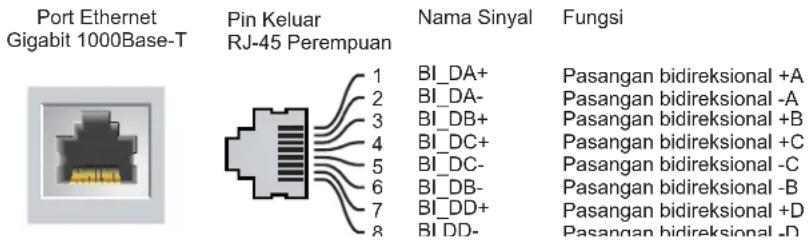
There are four 10/100/1000Base-T Gigabit Ethernet (RJ-45) ports. Gigabit Ethernet uses all eight wires and each pair is used in a bi-directional fashion, meaning the same pairs are used for both data transmission and reception. Figure 2 illustrates the CAT-5 pin-out found on an RJ-45 connector. The CAT-5 pin-out pairs the following pins on a 10/100/1000Base-T Gigabit Ethernet port: 1/2, 3/6, 4/5, and 7/8.
Figure 2 Gigabit Ethernet Port Pin-Out

Serial Console Port
A serial console port is provided for connection to a terminal, allowing for direct local management. The port's RJ-45 female connector accepts an RS-232 serial cable with a male connector.
Figure 3 Serial Console Port Pin-Out
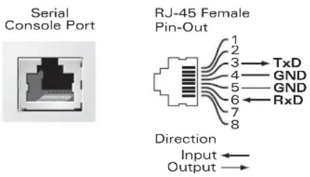
Communication settings for the serial console port are indicated in Table 1.
Table 1 Console Terminal Settings
| Baud Rate | Data Bits | Parity | Stop Bits | Flow Control |
| 9600 8 None 1 | None |
Caution: Do not connect an Access Point (AP) to the serial console port. The serial console port is compatible with only RS-232 devices. Non-RS-232 devices, such as APs, are not supported.
Serial Console Port Adaptor
A modular adaptor can be used to convert the RJ-45 (female) connector to a DB9 (male) connector. Refer to Figure 4 for complete details.
Figure 4 RJ-45 (female) to DB9 (male) Modular Adaptor Conversion

Figure 5 represents the W-3200 rear view.
Figure 5 W-3200 Rear View

AC Power Socket
The W-3000 Series Controllers supports integrated AC powering and the AC power socket on the rear of the unit is for use with an AC power cord (country-specific). Refer to “Power Management Specifications” on page 17 for power specification details.
LED Status Indicators
Table 2 W-3000 Series Controllers LED Status Indicators
| LED Function Indicator Status | |||
| POWER Input Power Status | Indicator | On (Solid Green) Power on | |
| Off No power | |||
| STATUS Module Status Indicator On (Solid Green) Device is operational | |||
| On (Solid Red) Device failed | |||
| On (Solid Amber) Device is loading software | |||
| Off No power | |||
| LNK 1000Base-X Ports | Link Status Indicator | On (Solid Green) | Link has been established |
| Off No link on port | |||
Table 2 W-3000 Series Controllers LED Status Indicators
| LED Function Indicator Status | |||
| ACT 1000Base-X ports | Activity Status Indicator | On (Blinking Green) | Port is transmitting or receiving data |
| Off No activity | |||
| LNK/ACT 10/100/1000Base-T Ports Link | Activity Status Indicator | On (Solid Green) Link has been established | |
| On (Blinking Green) Port is transmitting or receiving data | |||
| Off No link on port | |||
| 1000 10/100/1000Base-T Ports Interface | Speed Indicator On (Solid Green) | 1000 Mbps interface speed in use | |
| Off 10/100 Mbps interface speed in use | |||
The following tools and equipment are required for installing the Dell PowerConnect W-3000 Series Controllers:
- Rack Mount Bracket (x2, not used for tabletop installation)
- Suitable Screwdrivers
• AC Power Cord (country-specific)

Warning: Before performing the following procedure, review the safety instructions that came with the controller.
For a Telecom Rack:
- 6-32 x 1/4" Phillips Head Screws (6x, included)
- 12-24 x 5/8" Phillips Head Screws (4x, included)
For a Server Rack:
- 6-32 x 1/4" Phillips Head Screws (6x, included)
• M6 x 20mm Phillips Head Screws (4x, included)
• M6 Cage Nuts (4x, included) or M6 Cage Clips (4x, included)
Installation in a Telecom Rack
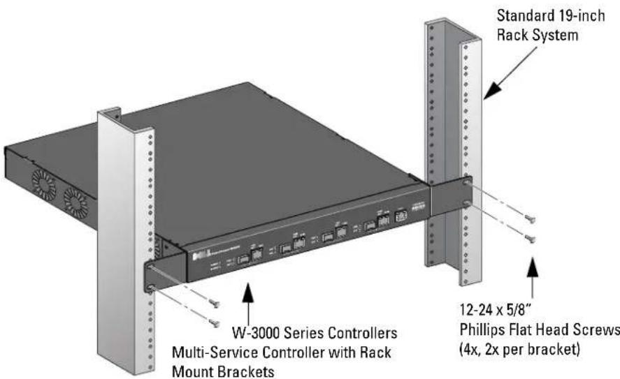
To install the W-3000 Series Controllers into a 19-inch (48.26 cm) rack system:
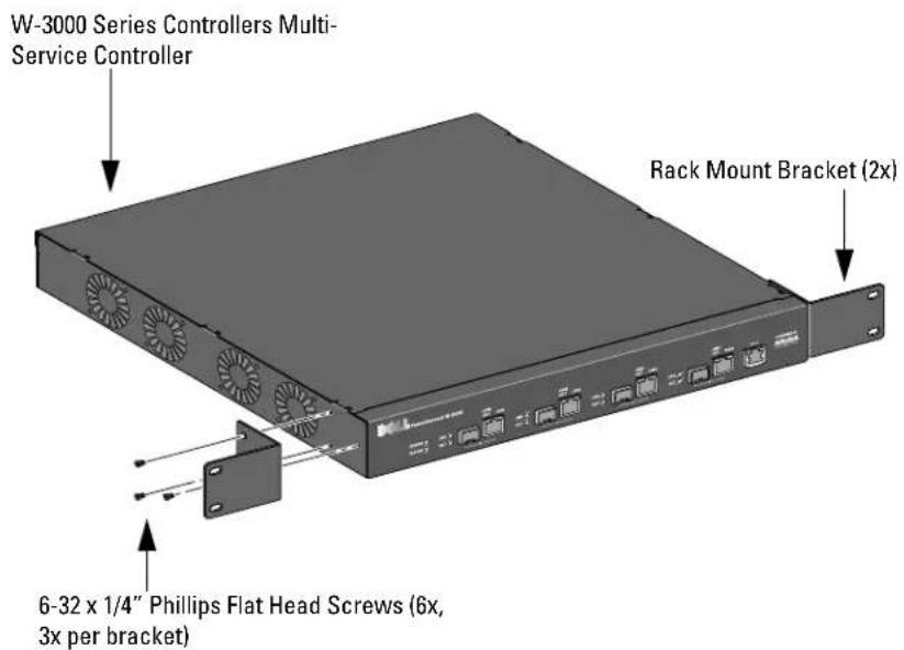
- Place a rack mount bracket over the mounting holes on one side of the controller (see Figure 1).
- Secure the bracket to the controller using three 6-32 x 1/4" phillips flat head screws and a suitable screwdriver.
- Repeat these steps on the opposite side of the controller.
Figure 1 Rack Mount Brackets
- Mount the controller within your organization's rack system using four 12-24 x 5/8" phillips flat head screws and a suitable screwdriver (see Figure 2).
Figure 2 Rack Mount Installation
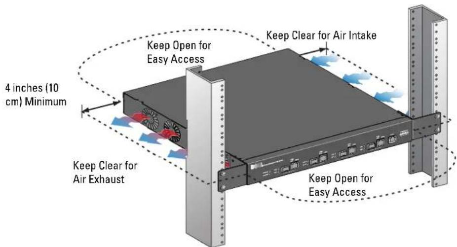
- Leave a minimum of four inches (10 cm) of space on the left and right side of the unit for proper air flow and ventilation (see Figure 3).
- Leave additional space in the front and back of the unit to access power cords, network cables, and LED status indicators (see Figure 3).
Figure 3 Air Flow Requirements
- Connect the AC power cord (country-specific) to the rear of the unit.
- Plug the opposite end of the power cord into an electrical outlet to power on the controller.
Installation in a Server Rack
To install a W-3000 Series Controllers controller into a 19-inch (48.26 cm) Server rack system:
Note: The following instructions describe the installation of your controller in a rack with unthreaded, square holes. For a rack with unthreaded, round holes, use the provided clip nuts instead.
- Place a rack mount bracket over the mounting holes on one side of the controller (see Figure 1).
- Secure the bracket to the controller using three 6-32 x 1/4" phillips head screws and a suitable screwdriver.
- Repeat these steps on the opposite side of the controller.
- Install the four cage nuts.
a. Begin by inserting the lower lip of the cage but over the square opening in the back of the rail.
b. Insert the small end of the cage-nut installation tool through the opening in the rail (from the front), and hook the tool over the top lip of the cage nut.
c. Push the cage nut in towards the rail while rotating the tool up and pulling the tool back toward you until the top lip of the cage nut snaps into position.
-
Mount the controller within your organization's rack system using four M6 x 20mm phillips head screws and suitable screwdriver.
-
Leave a minimum of four inches (10cm) of space on the left and right side of the unit for proper air flow and ventilation (see Figure 3).
-
Leave additional space in front and back of the unit to access power cords, network cables, and LED status indicators (see Figure 3).
-
Connect the AC power cord (country-specific) to the rear of the unit.
-
Plug the opposite end of the power cord into an electrical outlet to power the controller.


Note: W-3000 Series Controllers do not have a power on/off switch. Power to the unit is controlled by inserting (or unplugging) the power cord plug into your electric outlet.
Tabletop Deployment
To deploy an W-3000 Series Controllers on a flat surface, such as a tabletop:
- Insert the four rubber mounting feet to the bottom of the unit.
- Attach side bezels by snapping them into place.
- Place the unit on a hard flat surface.
Initial Setup and Network Connectivity
Once the physical installation is complete, run the initial setup on the controller to configure the IP address and other basic system information. For complete details and instructions, refer to the ArubaOS Quick Start Guide for the software version installed on your controller.
Removal
To remove the W-3000 Series Controllers from a 19-inch (48.26 cm) rack system:
- Disconnect the power to the controller by unplugging the power cord from the electrical outlet.
- Disconnect any other cables or devices attached to the controller.
- Loosen the four rack mount screws securing the controller to your organizations rack system.
- Remove the controller from the rack system.
Physical Specifications
• Device Dimensions (without rack mount brackets) (HxWxD):
■ All Models: 1.75" x 13.8" x 11.7"
■ All Models: 44 mm x 351 mm x 297 mm
Device Weight (with rack mount brackets):
• W-3200: 7.1 lbs/3.2 kgs
• W-3400/W-3600: 7.4 lbs/3.4 kgs
• Shipping Dimensions (IIxWxD):
■ All Models: 6.5" x 18.2" x 16.5"
■ All Models: 165 mm x 462 mm x 419 mm
- Shipping Weight:
■ W-3200: 9.4 lbs/4.3 kgs
■ W-3400/W-3600: 9.7 lbs/4.4 kgs
Power Management Specifications
Power Consumption
• W-3200: 35 W maximum
• W-3400: 45 W maximum
• W-3600: 60 W maximum
Power Specifications (AC Input Requirements)
W-3200:
■ AC Input Voltage: 90-264 V\~, Universal Input
■ AC Input Current: 1.5 A
■ AC Input Frequency: 47-63 Hz
W-3400/W-3600:
■ AC Input Voltage: 90-264 V\~, Universal Input
■ AC Input Current: 2.2 A
■ AC Input Frequency: 47-63 Hz
Operating Specifications
- Operating Temperature Range: 0°C to 40°C (32°F to 104°F)
- Operating Humidity Range: 5% to 95% (RH), non-condensing
Storage Specifications
• Storage Temperature Range: 0°C to 50°C (32°F to 122°F)
• Storage Humidity Range: 5% - 95% (RH), non-condensing
Safety and Regulatory Compliance
Dell provides a multi-language document containing country specific restrictions and additional safety and regulatory information for all Dell hardware products. The Dell PowerConnect W-Series Safety, Environmental, and Regulatory Information document is included with this product.


Caution: Use of controls or adjustments of performance or procedures other than those specified in this manual may result in hazardous radiation exposure.
This product complies with 21 CFR Chapter 1, Subchapter J, Part 1040.10, and IEC 60825-1: 1993, A1: 1997, A2: 2001, IEC 60825-2: 2000.
For continued compliance with the above laser safety standards, only approved Class 1 modules from our approved vendors should be installed in Dell products.
FCC Class A Device
This equipment has been tested and found to comply with the limits for a Class A digital device, pursuant to Part 15 of the FCC Rules. These limits are designed to provide reasonable protection against harmful interference when the equipment is operated in a commercial environment. This equipment generates, uses, and can radiate radio frequency energy and, if not installed and used in accordance with the instruction manual, may cause harmful interference to radio communications. Operation of this equipment in a residential area is likely to cause harmful interference in which case the user will be required to correct the interference at his own expense.
Industry Canada
This Class A digital apparatus complies with Canadian ICES-003.
NOM Information (Mexico Only)
The following information is provided on the device described in this document in compliance with the requirements of the official Mexican standards (NOM):
Importer: Dell Inc. de Mexico, S.A. de C.V. Paseo de la Reforma 2620-11° Piso Col. Lomas Atlas 11950 Mexico, D.F.
Model Number: 3200
• Supply Voltage: 90-264 V AC
• Frequency: 47-63 Hz
• Current consumption: 1.5 A
Model Number: 3400/3600
• Supply Voltage: 90-264 V AC
• Frequency: 47-63 Hz
• Current consumption: 2.2 A
Proper Disposal of Dell Equipment
For the most current information on Global Environmental Compliance and Dell products please see our website at www.dell.com.
European Union RoHS
RoHS
Dell products also comply with the EU Restriction of Hazardous Substances Directive 2002/95/E.C (RoHS). EU RoHS restricts the use of specific hazardous materials in the manufacture of electrical and electronic equipment. Specifically, restricted materials under the RoHS Directive are Lead (including Solder used in printed circuit assemblies), Cadmium, Mercury, Hexavalent Chromium, and Bromine. Some Dell products are subject to the exemptions listed in RoHS Directive Annex 7 (Lead in solder used in printed circuit assemblies). Products and packaging will be marked with the "RoIIS" label shown at the left indicating conformance to this Directive.
Dell PowerConnect W-3000 Serie Controller
Industry Canada....18

Ports Ethernet Gigabit 10/100/1000Base-T....9
Port console série 9
Ports Ethernet Gigabit 10/100/1000Base-T

This Class A digital apparatus complies with Canadian ICES-003.
Industry Canada....18
Puertos Gigabit Ethernet 10/100/1000Base-T

Industry Canada....18

Industry Canada....18
Port Ethernet 10/100/1000Base-T Gigabit....9
Port Konsol Serial....9
Adaptor Port Konsol Serial 9
Soket Daya AC 10
Indikator Status LED....10
Bab 2 Memasang Kontroler Seri W-3000 ....13
Industry Canada....18
Informasi NOM (Meksiko Saja)....19
Port Ethernet 10/100/1000Base-T Gigabit
Ada cmpat port (RJ-45) Ethernet Gigabit 10/100/1000Base-T. Ethernet Gigabit menggunakan kedelapan kawat dan setiap pasangan digunakan secara dua arah, yang berarti pasangan yang sama digunakan baik untuk pengiriman maupun penerimaan data. Gambar 2 menunjukkan pin keluar KAT-5 yang terdapat pada konektor RJ-45. Pin keluar KAT-5 menyandingkan pin berikut ini pada port Ethernet Gigabit 10/100/1000Base-T: 1/2, 3/6, 4/5, dan 7/8.
Gambar 2 Pin Keluar Port Ethernet Gigabit
Port Konsol Serial
7 PowerConnect W-3000 Series 1
7.
7.
8.
8....10/1000Base-X (SFP) nikiv
9....10/100/1000Base-T Gigabit Ethernet
9.
9.
10......AC 7269
10.
13. W-3000 Series 2
13.
13.
13.
15.
16.
16.
16.
17.
17.
17.
17.
18....FCC Class A Device
7 "PowerConnect W-3000 Series 1"
PowerConnect W-3000 Series
Multi-Service W-3200
10/100/1000Base-T Gigabit Ethernet
Bi-directional pair +A
Bi-directional pair -A
Bi-directional pair +B
Bi-directional pair +C
Bi-directional pair -C
Bi-directional pair -B
Bi-directional pair +D
Bi-directional pair -D
natural_image
3D rendering of a gray server rack with a labeled port and Hebrew text (no other symbols or text)AC 7000
:Dell PowerConnect W-3000 Series
.הכלההוּרָהוּרָהוּרָהוּרָהוּרָהוּרָהוּרָהוּרָהוּרָהוּרָהוּרָהוּרָהוּרָהוּרָהוּרָה

- Dell PowerConnect W-3000 Series Controllers
- Copyright
- Open Source Code
- Legal Notice
- Contents
- About This Guide....5
- Chapter 1 About the PowerConnect W-3000 Series Controllers....7
- Chapter 2 Installing the W-3000 Series Controllers ....13
- Appendix A Specifications, Safety & Compliance 17
- Guide Overview
- Related Documents
- Contacting Dell
- Minimum Software Requirements
- Package Checklist
- Model Overview
- 1000Base-X (SFP) Ports
- 10/100/1000Base-T Gigabit Ethernet Ports
- Serial Console Port
- Serial Console Port Adaptor
- AC Power Socket
- LED Status Indicators
- For a Telecom Rack:
- For a Server Rack:
- Installation in a Telecom Rack
- Installation in a Server Rack
- Tabletop Deployment
- Initial Setup and Network Connectivity
- Removal
- Physical Specifications
- Power Management Specifications
- Power Consumption
- Power Specifications (AC Input Requirements)
- Operating Specifications
- Storage Specifications
- Safety and Regulatory Compliance
- FCC Class A Device
- Industry Canada
- NOM Information (Mexico Only)
- Proper Disposal of Dell Equipment
- European Union RoHS
- RoHS
- Dell PowerConnect W-3000 Serie Controller
- Ports Ethernet Gigabit 10/100/1000Base-T
- Puertos Gigabit Ethernet 10/100/1000Base-T
- Bab 2 Memasang Kontroler Seri W-3000 ....13
- Port Ethernet 10/100/1000Base-T Gigabit
- Port Konsol Serial
- PowerConnect W-3000 Series 1
- W-3000 Series 2
- 17.
- 10/100/1000Base-T Gigabit Ethernet
- AC 7000
Brand : DELL
Model : PowerConnect W3200
Category : Controller