
CAM35 - Dashcam DOMETIC - Free user manual and instructions
Find the device manual for free CAM35 DOMETIC in PDF.
| Brand | Dometic |
| Model | CAM35 |
| Product type | Backup camera (reversing video system) |
| Available variants | CAM35 REAR, CAM35 REAR NAV, CAM35 TWIN, CAM35 TWIN NAV |
| Image sensor | 1/4" CMOS, approx. 345,000 pixels |
| Video standard | NTSC |
| Viewing angle | Approx. 150° (horizontal) / 60° (vertical), diagonal |
| Sensitivity | 1.5 lux |
| Operating voltage | 10 V to 16 V DC |
| Power consumption | 1 W |
| Operating temperature | -30 °C to +70 °C |
| Ingress protection rating | IP69k (waterproof, resistant to high-pressure cleaner with caution) |
| Vibration resistance | 10 g |
| Dimensions (W × H × D with bracket) | 80 × 30 × 33 mm |
| Weight | Approximately 0.25 kg |
| Intended use | Vehicles Fiat Ducato, Citroën Jumper, Peugeot Boxer (standard roof) from 2006 |
| Package contents | Camera, system cable, Y adapters (camera and monitor), NAV adapter (depending on version), mounting screws, instructions |
| Safety instructions | Disconnect the battery before installation; do not use a high-pressure cleaner; do not open the camera |
| Maintenance and cleaning | Clean with a soft, damp cloth; do not use sharp objects |
| Warranty | Statutory warranty; contact the dealer or manufacturer in case of defects |
| Disposal | Recycle the packaging and the product at the end of its life in accordance with local regulations |
Frequently Asked Questions - CAM35 DOMETIC
User questions about CAM35 DOMETIC
0 question about this device. Answer the ones you know or ask your own.
Ask a new question about this device
Download the instructions for your Dashcam in PDF format for free! Find your manual CAM35 - DOMETIC and take your electronic device back in hand. On this page are published all the documents necessary for the use of your device. CAM35 by DOMETIC.
USER MANUAL CAM35 DOMETIC
natural_image
Black plastic mechanical component with curved handle and circular end (no text or symbols)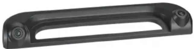
natural_image
Black plastic mechanical component with curved handle and two circular ports (no text or symbols visible)CAM35
EN
Rear View Video Camera
Installation and Operating Manual.....9
DE
Rückfahrvideokamera
natural_image
Simple line drawing of a mechanical or electrical component with no text, numbers, or symbols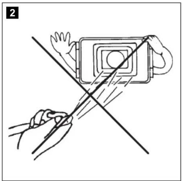
natural_image
Illustration of two hands using a device to cut a rectangular object with a diagonal line (no text or symbols)
natural_image
Simple line drawing of a device with a cross crossed out, no text or symbols present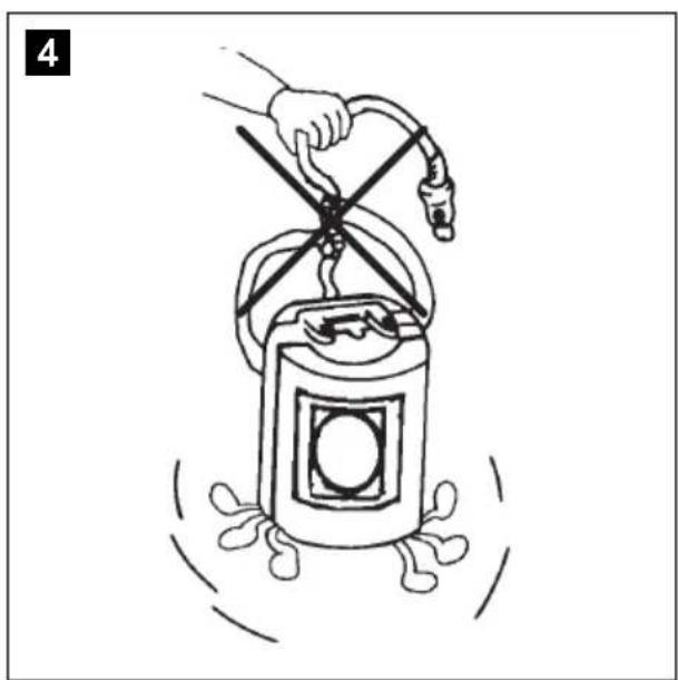
natural_image
Illustration of a hand using a windmill to lift a cylindrical device with a handle, surrounded by motion lines (no text or symbols)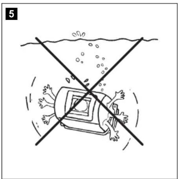
natural_image
Illustration of a person falling into a vehicle with a crosshair line crossing over water (no text or symbols)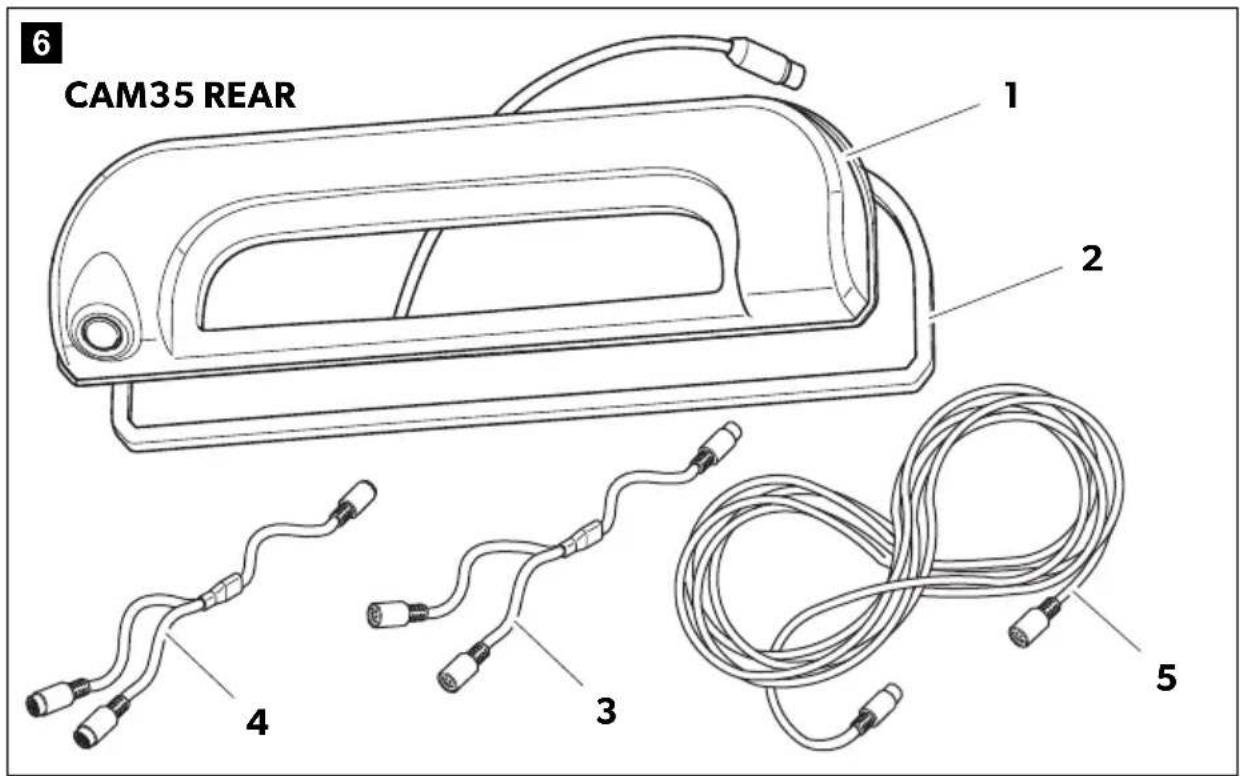

natural_image
Technical diagram of a mechanical assembly with two components, one showing a cable attachment and the other a conveyor belt (no text or symbols)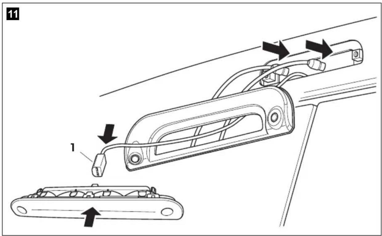
natural_image
Diagram showing two types of cable connectors labeled A and B, with arrows indicating connection points (no text or symbols beyond labels)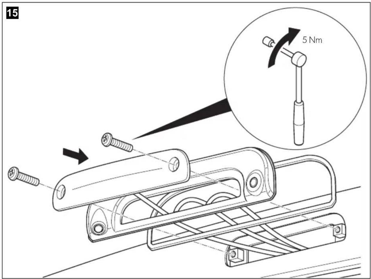
Please read this instruction manual carefully before installation and first use, and store it in a safe place. If you pass on the product to another person, hand over this instruction manual along with it.
Table of contents
1 Explanation of symbols....9
2 Safety and installation instructions .....10
3 Scope of delivery .....12
4 Intended use ....13
5 Technical description ....13
6 Fitting the camera....14
7 Cleaning and caring for the camera .....17
8 Warranty ....17
9 Disposal....17
10 Technical data....18
1 Explanation of symbols

WARNING!
Safety instruction: Failure to observe this instruction can cause fatal or serious injury.

NOTICE!
Failure to observe this instruction can cause material damage and impair the function of the product.

NOTE
Supplementary information for operating the product.
2 Safety and installation instructions
Please observe the prescribed safety instructions and stipulations from the vehicle manufacturer and service workshops.
The manufacturer accepts no liability for damage in the following cases:
- Faulty assembly or connection
- Damage to the product resulting from mechanical influences and excess voltage
• Alterations to the product without express permission from the manufacturer - Use for purposes other than those described in the operating manual
Please note the following:
- To prevent the risk of short circuits, always disconnect the negative terminal of the vehicle's electrical system before working on it.
If the vehicle has an additional battery, its negative terminal should also be disconnected.
- Inadequate supply cable connections could result in short circuits, causing:
- Cable fires
- The airbag being triggered
– Damage to electronic control equipment
– Electrical malfunctions (indicators, brake light, horn, ignition, lights)
- When working on the following cables, only use insulated cable terminals, plugs and flat sockets:
- 30 (direct supply from positive battery terminal)
- 15 (connected positive terminal, behind the battery)
- 31 (return cable from the battery, earth)
- 58 (reversing light)
Do not use porcelain wire connectors.
- Use a crimping tool to connect the cables.
- Screw the cable when connecting cable 31 (earth)
- Screw on the cable using a cable terminal and serrated washer to one of the vehicle's earth bolts or
- Screw the cable to the bodywork using a cable terminal and a self-tapping screw
Make sure there is a good earth connection.
If you disconnect the negative terminal of the battery, all data stored in the volatile memories will be lost.
- The following data must be reset, depending on the vehicle equipment options:
- Radio code
- Vehicle clock
- Timer
- On-board computer
- Seat position
You can find instructions for making these settings in the operating manual.
Observe the following installation instructions:
- Secure the parts of the camera which are installed in the vehicle in such a way that they cannot become loose under any circumstances (sudden braking, accidents) and cause injuries to the occupants of the vehicle.
- Secure any parts of the system concealed by the bodywork in such a manner that they cannot be come loose or damage other parts or cables, or impair vehicle functions (steering, pedals, etc).
- To prevent damage when drilling, make sure there is sufficient space on the other side for the drill head to emerge.
- Deburr all drill holes and treat them with a rust-protection agent.
- Always follow the safety instructions of the vehicle manufacturer. Some work (e.g. on retention systems such as the AIRBAG etc.) may only be performed by qualified specialists.
Observe the following instructions when working with electrical parts:
- When testing the voltage in electrical cables, only use a diode test lamp or a voltmeter.
Test lamps with a bulb consume too much voltage, which can damage the vehicle's electronic system.
- When making electrical connections, ensure that:
– they are not kinked or twisted
- they do not rub on edges
– they are not laid in sharp-edged ducts without protection (fig. 1, page 3).
• Insulate all connections.
- Secure the cables against mechanical wear by using cable binders or insulating tape, for example on existing cables.
The camera is watertight. However, the seals on the camera cannot withstand a high-pressure cleaner (fig. 2, page 3). Therefore, you should observe the following instructions when handling the camera:
- People (including children) whose physical, sensory or mental capacities or whose lack of experience or knowledge prevent them from using this product safely should not use it without the supervision or instruction of a responsible person.
- Do not open the camera, as this impairs the leak tightness and the function of the camera (fig. 3, page 3).
- Do not pull at the cables, as this impairs the tightness and the function of the camera (fig. 4, page 3).
- The camera is not suitable for use under water (fig. 5, page 3)!
3 S c o p e o f d
No. in fig. 6, page 4 Quantity Description Ref. no.
| 11 Camera CAM35 | ||
| CAM35 REAR | 9102000134 | |
| CAM35 REAR NAV | 9102000133 | |
| CAM35 TWIN | 9102000132 | |
| CAM35 TWIN NAV | 9102000131 | |
| 21 Seal - | ||
| 31 CAM35 Y adapter CAM 9600000552 | ||
| 41 CAM35 Y adapter MON 9600000553 | ||
| 51 System cable 9600000137 | ||
| -1 NAV adapter (only CAM35 REAR NAV or CAM35 TWIN NAV) | 9600000558 | |
| -2 Fastening bolts 6 x 25 mm | ||
| - - Installation and operating manual | ||
4 Intended use
The double camera CAM35 is primarily intended for use in the vehicles Fiat Ducato, Citroën Jumper, Peugeot Boxer starting from model year 2006 with single roof. The camera console is mounted between the bodywork and the brake light. It can be used in video systems to observe the space around the vehicle from the driver's seat when manoeuvring or parking, for example.

WARNING!
Danger of personal injury by vehicle.
Reversing video systems are designed merely as an additional aid for reversing, however this does not relieve you of the duty to take proper care when reversing.
5 Technical description
The reversing camera and the long-distance camera (only CAM35 TWIN) are housed in one console for the original brake light. The camera image is transferred to a monitor via a system cable. The CAM35 is also suitable for connection to the original Fiat navigation system Uconect, as the cameras provide an NTSC video signal.
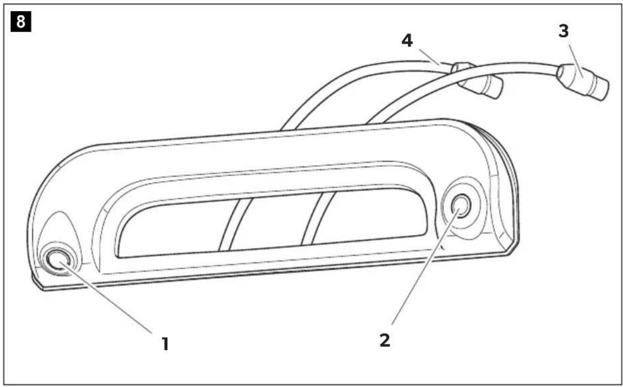
The camera consists of the following elements:
| No. in fig. 8, page 5 | Description |
| 1 Reversing camera | |
| 2 Long-distance camera (only CAM35 TWIN) | |
| 3 | 6-pin connection cable for long-distance camera (only CAM35 TWIN) |
| 4 6-pin connection cable for reversing camera | |
Only for CAM35 TWIN
In the CAM35 TWIN, a monitor with two video inputs must be connected that can be switched between the image of the reversing and the long-distance cameras.
The long-distance camera transmits the image as if you were looking in the rear view mirror.
Only for CAM35 NAV
The cameras CAM35REAR NAV and CAM35 TWIN NAV can be connected to monitors from other manufacturers. A universal adapter is included (CAM35 NAV adapter).
6 Fitting the camera
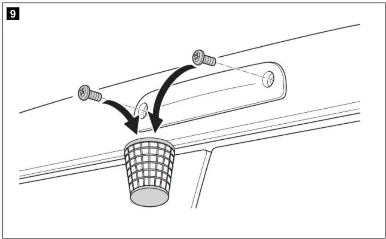
6.1 Dismantling the brake light
▶ Remove the two screws of the brake light (fig. 9, page 5).
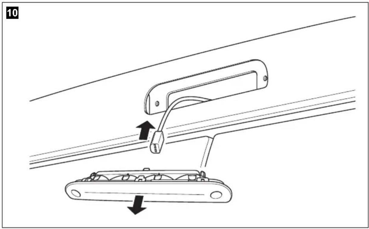
▶ Remove the plug of the brake light (fig. 10, page 6).
6.2 Laying cables

NOTICE! Beware of damage.
- When drilling holes, check beforehand that there is sufficient space on the other side for the drill head to come out.
- Cables and connections that are not properly installed will cause malfunctions or damage to components. Correct installation of cables and connections ensures lasting and trouble-free operation of the retrofitted components.
- The cables may not be exposed for long periods to solvents such as benzene, since solvents can damage the cable.
Therefore, please observe the following instructions:
- As far as possible, use original ducts for laying the cables, or other suitable options such as panelling edges, ventilation grilles or dummy plugs. If no openings are available, you must drill holes for the cables. Check beforehand that there is sufficient space on the other side for the drill head to emerge.
-
Wherever possible, lay cables inside the vehicle, as they are better protected there than outside.
If you do need to lay a cable outside the vehicle, ensure that it is well fastened (use additional cable ties, insulating tape etc.). -
To prevent damage to the cables when laying them, ensure that they are far enough away from hot or moving vehicle components (exhaust pipes, drive shafts, light systems, fans, heaters, etc.). Use corrugated piping or other protective materials to protect against mechanical wear.
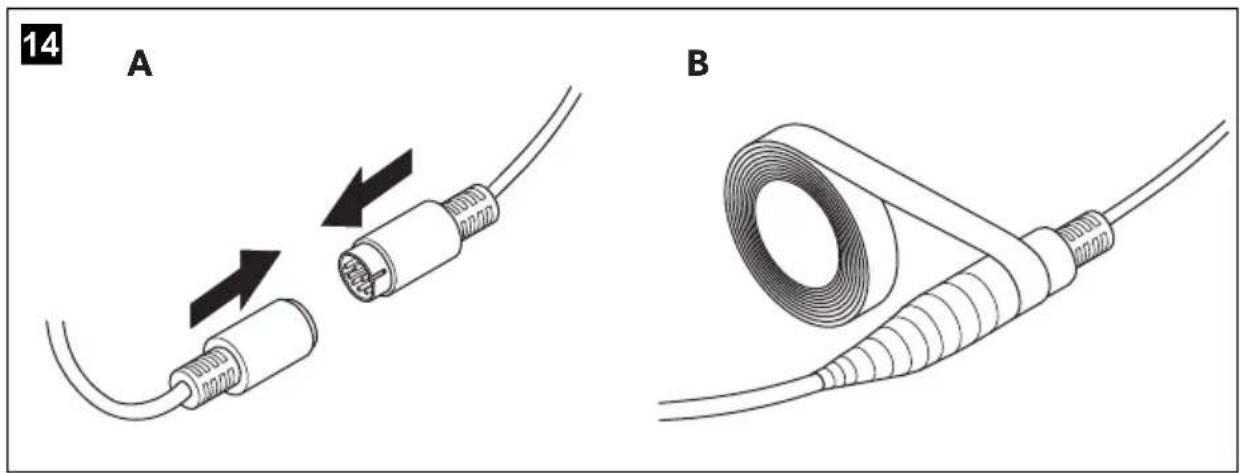
- Screw on the plug connections for the connecting cables to protect them against water penetration (fig. 14, page 7).
- When laying the cables, make sure:
– they are not kinked or twisted
– they do not rub on edges
– they are not laid in sharp-edged ducts without protection.
- Attach the cables securely in the vehicles to prevent tripping hazards. This can be performed by using cable binders, insulating tape or gluing in place with adhesives.
▶Lay the system cable.
6.3 Establishing the electrical connection for the camera

NOTE
- Lay the camera cable so that, should you need to remove the camera, you can access the plug connection between the camera and the extension cable easily. This greatly facilitates the disassembly.
- To minimise corrosion in the plug, apply a small amount of grease, such as pin grease, in one of the plugs.
▶ Guide the connector of the brake light through the console.
▶ Re-attach the plug (fig. 11 1, page 6) of the brake light onto the brake light.
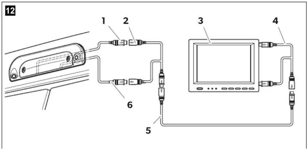
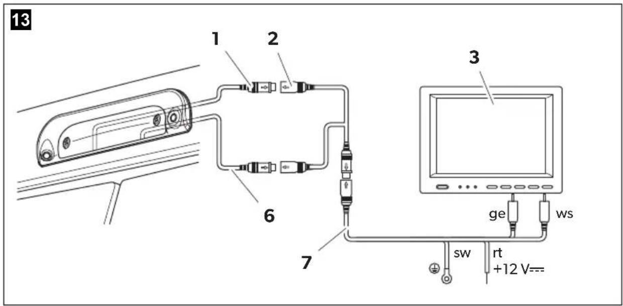
▶ Connect the camera as shown in fig. 12, page 7 to fig. 14, page 7.
Legend to fig. 12, page 7 and fig. 13, page 7:
No. Description
1 6-pin connection cable for reversing camera
2 Y-adapter camera
3 Monitor
4 Y-adapter monitor
5 S y s t e m c a b l e
6 6-pin connection cable for long-distance camera (only CAM35 TWIN)
7 NAV adapter (only CAM35 NAV)
ws white, video signal 1
ge yellow, video signal 2
sw black
rt red
6.4 Fitting the camera

NOTICE!
Make sure to guide the camera cables in the console bottom up to the notches so that the cables are not pinched.
Proceed as follows (fig. 15, page 8):
▶Secure the brake light and the console with two 6 x 25 mm fastening screws.
7 Cleaning and caring for the camera

NOTICE! Beware of damage.
Do not use any sharp or hard objects for cleaning since they may damage the device.
▶ Clean the camera with a soft, damp cloth from time to time.
8 W a r r a n t y
The statutory warranty period applies. If the product is defective, please contact the manufacturer's branch in your country (see the back of the instruction manual for the addresses) or your retailer.
For repair and guarantee processing, please send the following items:
- Defect components
• A copy of the receipt with purchasing date - A reason for the claim or description of the fault
9 D i s p o s a l
▶ Place the packaging material in the appropriate recycling waste bins wherever possible.

If you wish to finally dispose of the product, ask your local recycling centre or specialist dealer for details about how to do this in accordance with the applicable disposal regulations.
10 Technical data
| PerfectViewCAM35 REAR | PerfectViewCAM35 REAR NAV | |
| Ref. no.: 9102000134 9102000133 | ||
| Image sensor: 1/4" CMOS | ||
| Pixels: Approx. 345.000 pixels | ||
| Video standard: NTSC | ||
| Sensitivity: 1.5 lux | ||
| Viewing angle: Approx. 150°/60° diagonal | ||
| Operating voltage: | 10 V--- to 16 V--- | |
| Consumption: 1 W | ||
| Operating temperature: -30 °C to +70 °C | ||
| Protection class: | IP69k | |
| Vibration resistance: | 10g | |
| Dimensions W x H x D(with bracket): | 80 x 30 x 33 mm | |
| Weight: Approx. 0.25 kg | ||
| PerfectViewCAM35 TWIN | PerfectViewCAM35 TWIN NAV | |
| Ref. no.: 9102000132 9102000131 | ||
| Image sensor: 1/4" CMOS | ||
| Pixels: Approx. 345000 pixels | ||
| Video standard: NTSC | ||
| Sensitivity: 1.5 lux | ||
| Viewing angle: Approx. 150°/60° diagonal | ||
| Operating voltage: | 10 V--- to 16 V--- | |
| Consumption: 1 W | ||
| Operating temperature: -30 °C to +70 °C | ||
| Protection class: IP69k | ||
| Vibration resistance: | 10g | |
| Dimensions W x H x D(with bracket): | 80 x 30 x 33 mm | |
| Weight: Approx. 0.25 kg | ||
5 Description technique
Dometic Australia Pty. Ltd.
1 John Duncan Cour
Varsity Lakes QLD 4227
1800 212121
+61 7 55076001
Mail: sales@dometic.com.au
AUSTRIA
Dometic Austria GmbH
Neudorferstraße 108
A-2353 Guntramsdorf
+43 2236 908070
+43 2236 90807060
Mail: info@dometic.at
BENELUX
Dometic Branch Office Belgium
Zincstraal 3
B-1500 Halle
+32 2 3598040
+32 2 3598050
Mail: info@dometic.be
BRAZIL
Dometic DO Brasil LTDA
Avenida Paulista 1754, conj. 111
SP 01310-920 Sao Paulo
+551132513352
+551132513362
Dometic Group Asia Pacific
Suites 2207-11 · 22/F · Tower 1
The Gateway · 25 Canton Road,
Tsim Sha Tsui · Kowloon
+852 2 4611386
+852 2 4665553
Mail: info@waeco.com.hk
HUNGARY
Dometic Zrt. Sales Office
Kerékgyártó u. 5.
H-1147 Budapest
+3614684400
+3614684401
Dometic Italy S.r.l.
Via Virgilio, 3
I-47122 Forlì (FC)
+39 0543 754901
+39 0543 754983
Mail: vendite@dometic.it
JAPAN
Dometic KK
Maekawa-Shibaura, Bldg. 2
2-13-9 Shibaura Minato-ku
Tokyo 108-0023
+81 3 5445 3333
+81 3 5445 3339
Mail: info@dometic.jp
MEXICO
Circuito Médicos No. 6 Local 1
Colonia Ciudad Satélite
CP 53100 Naucalpan de Juárez
Estado de México
+52 55 5374 4108
+52 55 5393 4683
Mail: info@dometic.com.mx
NETHERLANDS
Dometic Benelux B.V.
Ecustraat 3
NL-4879 NP Etten-Leur
+31 76 5029000
+31 76 5029019
Mail: info@dometic.nl
NEW ZEALAND
Dometic New Zealand Ltd.
PO Box 12011
Penrose
Auckland 1642
+6496221490
+6496221573
Mail: customerservices@dometic.co.nz
NORWAY
Dometic Norway AS
∅sterøyveien 46
N-3232 Sandefjord
+47 33428450
+47 33428459
Mail: firmapost@dometic.no
POLAND
Dometic Poland Sp. z o.o.
Ul. Puławska 435A
PL-02-801 Warszawa
+48 22 414 3200
+48 22 414 3201
Mail: info@dometic.pl
PORTUGAL
Dometic Spain, S.L.
Komsomolskaya square 6-1
RU-107140 Moscow
+7 495 780 79 39
+7 495 916 56 53
Mail: info@dometic.ru
SINGAPORE
Dometic Pte Ltd
18 Boon Lay Way 06-140 Trade Hub 21
Singapore 609966
+65 6795
+65 6862 6620
Mail: dometic@dometic.com.sg
SLOVAKIA
Dometic Slovakia s.r.o. Sales Office Bratislava
Nádražná 34/A
900 28 Ivánka pri Dunaji
/ +421 2 45 529 680
Mail: bratislava@dometic.com
SOUTH AFRICA
Dometic (Pty) Ltd.
Regional Office
South Africa & Sub-Saharan Africa
2 Avalon Road
West Lake View Ext 11
Modderfontein 1645
Johannesburg
+27 11 4504978
+27114504976
Mail: info@dometic.co.za
SPAIN
Dometic Spain S.L.
Avda. Sierra del Guadarrama, 16
E-28691 Villanueva de la Cañada
Madrid
+34 91 833 60 89
+34 900 100 245
Mail: info@dometic.es
SWEDEN
Dometic Scandinavia AB
Gustaf Melins gata 7
Dometic Switzerland AG
Riedackerstrasse 7a
CH-8153 Rümlang
+41 44 8187171
+41 44 8187191
Mail: info@dometic.ch
UNITED ARAB EMIRATES
Dometic Middle East FZCO
P.O.Box 17860
S-D 6, Jebel Ali Freezone
Dubai
+97148833858
+97148833868
Mail: info@dometic.ae
UNITED KINGDOM
Dometic UK Ltd.
Dometic House, The Brewery
Blandford St. Mary
Dorset DT119LS
+44 344 626 0133
+44 344 626 0143
Mail: customerservices@dometic.co.uk
USA
Dometic RV Division
1120 North Main Street
Elkhart, IN 46515
+1574-264-2131


- CAM35
- Rear View Video Camera
- Rückfahrvideokamera
- Table of contents
- Explanation of symbols
- WARNING!
- NOTICE!
- NOTE
- Safety and installation instructions
- Please observe the prescribed safety instructions and stipulations from the vehicle manufacturer and service workshops.
- S c o p e o f d
- Intended use
- Technical description
- Only for CAM35 TWIN
- Only for CAM35 NAV
- Fitting the camera
- Dismantling the brake light
- Laying cables
- NOTICE! Beware of damage.
- Establishing the electrical connection for the camera
- Legend to fig. 12, page 7 and fig. 13, page 7:
- No. Description
- Fitting the camera
- Cleaning and caring for the camera
- W a r r a n t y
- D i s p o s a l
- Description technique
- AUSTRIA
- BENELUX
- BRAZIL
- HUNGARY
- JAPAN
- MEXICO
- NETHERLANDS
- NEW ZEALAND
- NORWAY
- POLAND
- PORTUGAL
- SINGAPORE
- SLOVAKIA
- SOUTH AFRICA
- SPAIN
- SWEDEN
- UNITED ARAB EMIRATES
- UNITED KINGDOM
- USA
Brand : DOMETIC
Model : CAM35
Category : Dashcam