
PerfectView CAM 80 NAV - Dashcam DOMETIC - Free user manual and instructions
Find the device manual for free PerfectView CAM 80 NAV DOMETIC in PDF.
| Product type | Dashcam |
| Brand | Dometic |
| Model | PerfectView CAM 80 NAV |
| Supply voltage | 12 V – 24 V DC |
| Power consumption (control unit) | Max. 0.5 W (without camera) |
| Camera type | Reversing camera with motorized shutter |
| Connectivity | Cinch video output (RCA) |
| Features | Activation by reverse lights, manual switching possible via switch |
| Dimensions (control unit) | 117 x 50 x 25 mm |
| Installation | Interior mounting under dashboard, screw fixing |
| Package contents | Control unit with cables, toggle switch, mounting material, manual |
| Intended use | Reversing video system for vehicles |
| Compatibility | Screens with Cinch video input, cameras CAM33, CAM44, CAM80CM |
| Settings | DIP switches for camera selection and image inversion |
| Maintenance | Clean with a soft, dry cloth, without abrasive products |
| Safety | Disconnect the battery before installation, entrust electrical work to a professional |
| Warranty | Applicable legal warranty |
| General information | Detailed instruction manual provided with mounting diagrams |
Frequently Asked Questions - PerfectView CAM 80 NAV DOMETIC
User questions about PerfectView CAM 80 NAV DOMETIC
0 question about this device. Answer the ones you know or ask your own.
Ask a new question about this device
Download the instructions for your Dashcam in PDF format for free! Find your manual PerfectView CAM 80 NAV - DOMETIC and take your electronic device back in hand. On this page are published all the documents necessary for the use of your device. PerfectView CAM 80 NAV by DOMETIC.
USER MANUAL PerfectView CAM 80 NAV DOMETIC
natural_image
Line drawing of a rectangular electronic device with labeled ports and wires (no readable text or symbols)AMP100
EN
Connection Box
Installation and Operating Manual ..... 6
DE
Anschlussbox
Montage- und Bedienungsanleitung ... 15
FR
Boîte de commande
Instructions de montage
et de service .... 24
ES
Caja de distribución
Instrucciones de montaje y de uso .....33
PT
Caixa de conexão
Instruções de montagem e manual de instruções ....42
IT
Scatola di comando
Istruzioni di montaggio e d'uso ..... 51
NL
Schakelbox
Montagehandleiding en gebruiksaanwijzing....60
DA
Kontrolboks
Monterings- og betjeningsvejledning...69
SV
Kopplingsbox
Monterings- och bruksanvisning.....78
NO
Koblingsboks
Monterings- og bruksanvisning ..... 87
FI
Kytkinrasia
Asennus- ja käyttöohje. 96
RU
Клеммная коробка
Инструкция по монтажу
и эксплуатации.... 105
PL
Skrzynka przyłączeniowa
Instrukcja montażu i obsługi .....114
SK
Prípojný box
Návod na montáž a uvedenie
do prevádzky .... 123
CS
Rozvodná skříňka
Návod k montáži a obsluze ..... 132
HU
Csatlakozódoboz
Szerelési és használati útmutató .....141
1
1
natural_image
Isometric line drawing of a mechanical device with no visible text or symbols2
natural_image
Line drawing of a digital multimeter with connected cables and ports (no text or symbols)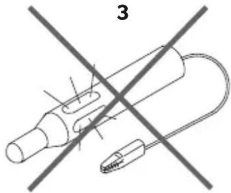
natural_image
Diagram of a mechanical device with two crossed lines and a labeled section '3' (no text or symbols on the diagram itself)4
natural_image
Line drawing of a ruler with measurement markings (no text or symbols)5
6
natural_image
Simple line drawing of a hammer with a triangular head and handle (no text or symbols)7
natural_image
Three cylindrical objects with diagonal striped patterns, no text or symbols present8
natural_image
Line drawing of a handheld electric shaver with no text or symbols9
natural_image
Three types of screwdrivers shown in line drawings (no text or symbols)10
natural_image
Line drawing of a handheld device with ventilation slots and handle (no text or symbols)11 12 13
natural_image
Line drawing of a pliers or crimping tool with no text or symbols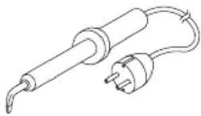
natural_image
Line drawing of a soldering iron with a terminal plug and power outlet (no text or symbols)
natural_image
Technical line drawing of a welding process with arrows indicating motion (no text or symbols)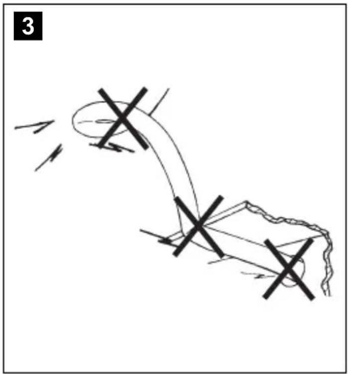
Please read this instruction manual carefully before installation and first use, and store it in a safe place. If you pass on the product to another person, hand over this instruction manual along with it.
Table of contents
1 Explanation of symbols....6
2 Safety and installation instructions....7
3 Scope of delivery 9
4 Intended use....9
5 Technical description 9
6 Installation and connection 11
7 Setting the control box....13
8 Warranty 13
9 Disposal....14
10 Technical data....14
1 Explanation of symbols

WARNING!
Safety instruction: Failure to observe this instruction can cause fatal or serious injury.

CAUTION!
Safety instruction: Failure to observe this instruction can lead to injury.

NOTICE!
Failure to observe this instruction can cause material damage and impair the function of the product.

NOTE
Supplementary information for operating the product.
2 Safety and installation instructions
The manufacturer accepts no liability for damage in the following cases:
- Damage to the product resulting from mechanical influences and excess voltage
• Alterations to the product without express permission from the manufacturer - Use for purposes other than those described in the operating manual
Please observe the prescribed safety instructions and stipulations from the vehicle manufacturer and service workshops.

WARNING!
Inadequate supply cable connections could result in short circuits, which could have as a consequence that:
- Cable fires occur
•The airbag is triggered
• Electronic control devices are damaged
• Electric functions fail (indicators, brake light, horn, ignition, lights)

NOTICE!
To prevent the risk of short circuits, always disconnect the negative terminal of the vehicle's electrical system before working on it.
If the vehicle has an additional battery, its negative terminal should also be disconnected.
Please observe the following instructions:
- When working on the following cables, only use insulated cable lugs, plugs and flat push-on receptacles:
- 30 (direct supply from positive battery terminal)
- 1 5 ( connected positive terminal, behind the battery)
- 31 (return line from the battery, earth)
-
L (indicator lights left)
-R(indicator lights right)
Do not use terminal strips. -
Use a crimping tool to connect the cables.
- When connecting to cable 31 (earth), screw the cable
- to the vehicle's earth bolt with a cable lug and a gear disc or
- to the sheet-metal bodywork with a cable lug and a self-tapping screw.
Ensure that there is a good earth connection.
If you disconnect the negative terminal of the battery, all data stored in the volatile memories will be lost.
- The following data must be set again, depending on the vehicle equipment options:
- Radio code
- Vehicle clock
- Timer
- On-board computer
- Seat position
You can find instructions for making these settings in the appropriate operating instructions.
Observe the following installation instructions:

CAUTION!
- Secure the parts installed in the vehicle in such a way that they cannot become loose under any circumstances (sudden braking, accidents) and cause injuries to the occupants of the vehicle.
- Secure any parts of the system covered by the bodywork in such a manner that they cannot be come loose or damage other parts and cables or impair vehicle functions (steering, pedals, etc).
- Always follow the safety instructions of the vehicle manufacturer. Some work (e.g. on retention systems such as the AIRBAG etc.) may only be performed by qualified specialists.

NOTICE!
- To prevent damage when drilling, make sure there is sufficient space on the other side for the drill head to come out.
- Deburr all drill holes and treat them with a rust-protection agent.
Observe the following instructions when working with electrical parts:

NOTICE!
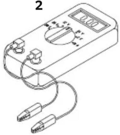
- When testing the voltage in electrical cables, only use a diode test lamp or a voltmeter.
Test lamps with an illuminant take up voltages which are too high and which can damage the vehicle's electronic system.
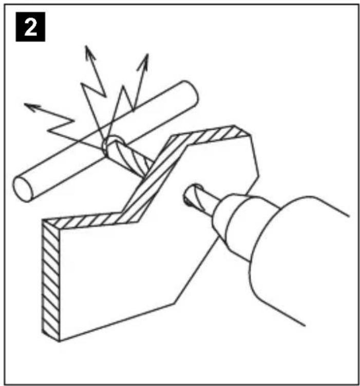
- When making electrical connections, ensure that:
– they are not kinked or twisted
– they do not rub on edges
– they are not laid in sharp edged ducts without protection.
• Insulate all connections.
- Secure the cables against mechanical wear with cable binders or insulating tape, for example to existing cables.
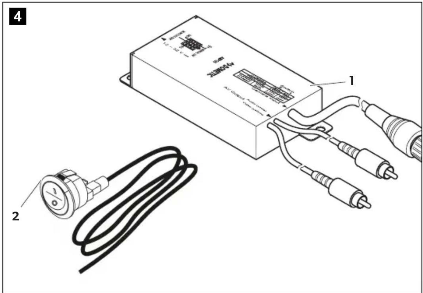
| 3 | S | c | o | p | e | o | f | d | e | l |
No. in fig. 4, page 4 Quantity Description Ref. no.
11 Control box with cable set
21 Rocker switch RV-AMP-SW
- 1 Installation material with cable fasteners
- 1 Installation and operating manual
4 l n t e n d e d u s
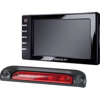
AMP100 (ref. no. 9600000210) is a control box for connecting the camera models CAM33, CAM44 and CAM80CM with motor-driven protective flaps to a monitor for use as a reversing video system.
5 Technical description
AMP100 is used to connect cameras CAM33, CAM44 and CAM80CM to a monitor with cinch video input (RCA). The control box supplies the control signal for the camera's motor-driven protective cover and the activation signal for the monitor. It also provides a proper supply of power to the camera.
In default mode, the camera is activated when you switch on the monitor or engage the reverse gear. The monitor is also activated when you engage the reverse gear.
If a video source in addition to the camera, such as a navigation system or DVD player, is connected to the monitor, you need to set and connect the control box accordingly. In that case, the control signal for the camera protective cover is not triggered when you switch on the monitor but only when you shift into reverse gear.
If you would then like to use the camera when the vehicle is parked or when driving forwards, you must install the supplied rocker switch.
The control box can be connected to 12 V to 24 V DC voltage.
5.1 Connections
The control box has the following connections:
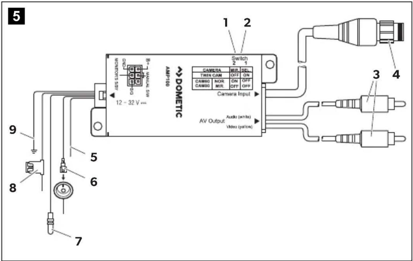
No. in fig. 5, page 5
Connection description
3 AV output (cinch plug) for connecting...
• to a navigation system with an AV input (cinch socket)
• to another monitor with an AV input (cinch socket) or to a video recorder
| 4 | C | a | m | e | r | a | c |
| 5 Green control cable (+ signal) for connecting the positive cable of the reversing lightWhen you shift into reverse gear, the control box is activated via this cable. | |||||||
| 6 Black control line (+ signal) with flat plug fitting for connection of the RV-AMP-SW rocker switch.This line must be connected when a video source in addition to the reversing video camera – such as a navigation system or DVD player – is connected to the monitor and you would like to activate the camera when parked or driving forwards. | |||||||
| 7 Black control line (+ signal) with round plug lug for connection to the monitor’s S/BY signal input.The monitor is switched on via this line when the control box is activated. | |||||||
| 8 | Red cable: connection to 12 V to 24 V positive (e.g. connected positive terminal, terminal 15) | ||||||
| 9 Brown cable: connection to earth (terminal 31) | |||||||
6 Installation and connection
6.1 Tools required
For installation and assembly, you will need the following tools:
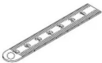
• Measuring ruler (fig. 1 4, page 3)
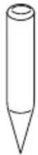
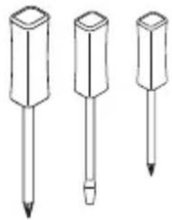
• Centre punch (fig. 1 5, page 3)
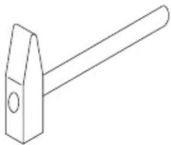
- Hammer (fig. 1 6, page 3)
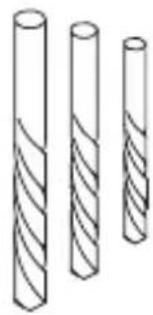
- Drill bit set (fig. 1 7, page 3)
• Electric drill (fig. 1 8, page 3)
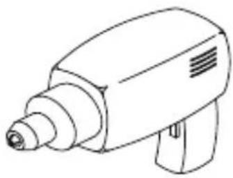
- Screwdriver (fig. 1 9, page 3)
To establish and test the electrical connection, the following tools are required:
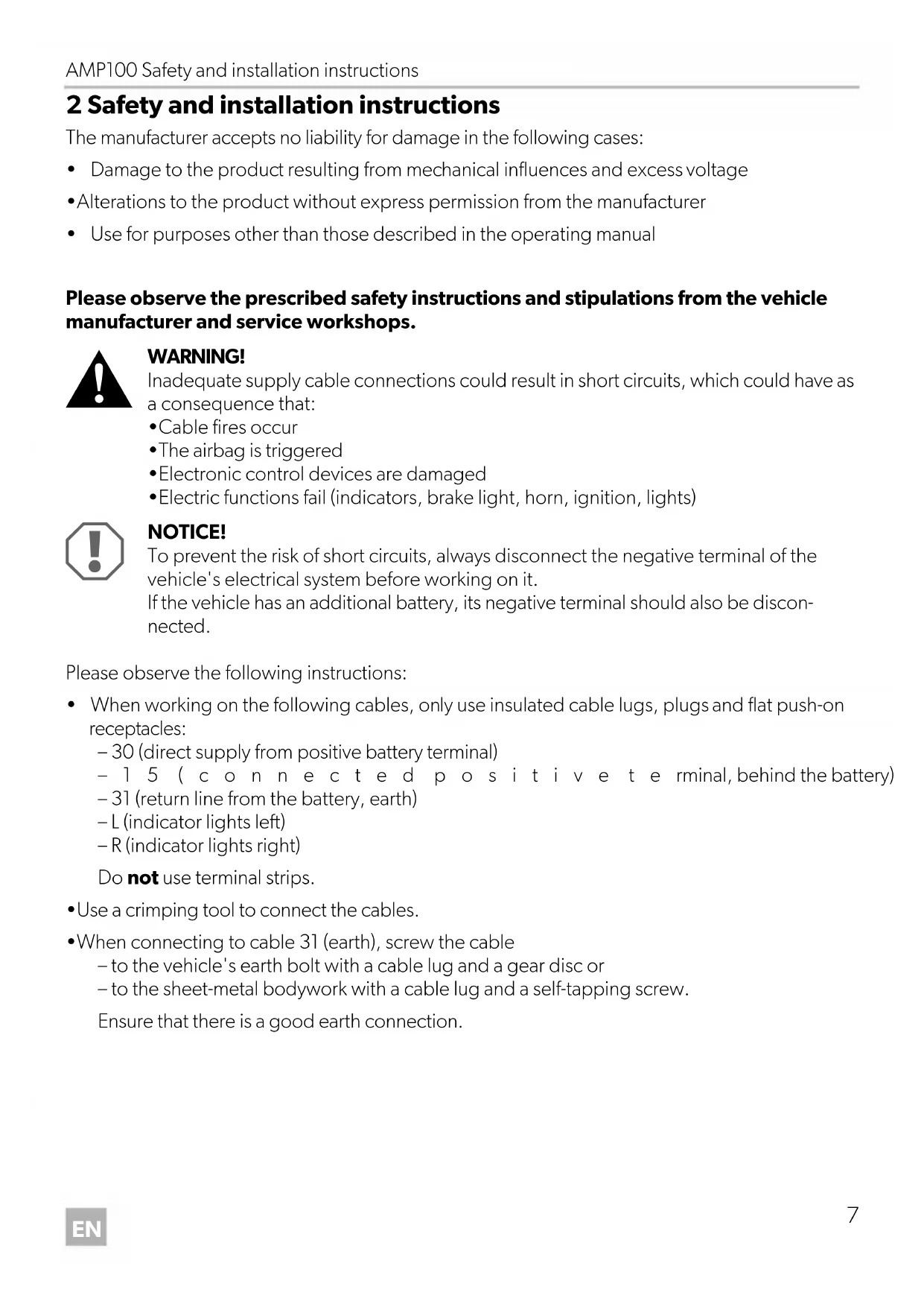
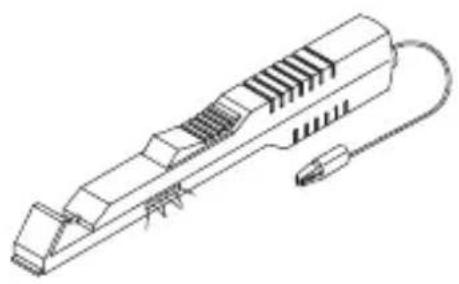
• Diode test lamp (fig. 1 1, page 3) or voltmeter (fig. 1 2, page 3)
- Insulating tape
- Heat shrinking sleeve
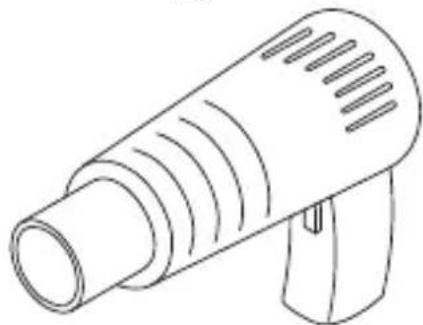
• Hot air blower (fig. 1 10, page 3)
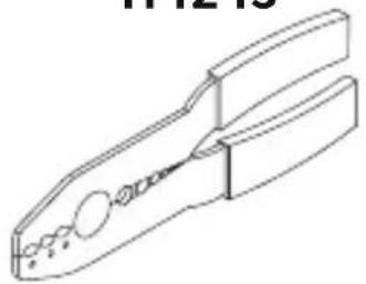
• Crimping tool (fig. 1 11, page 3)
- Soldering iron (optional) (fig. 1 12, page 3)
- Solder (optional) (fig. 1 13, page 3)
• Cable bushing sleeves (optional)
6.2 Installing and connecting the control box
The control box is supplied ready for installation.
▶ Install the control box in a location protected from water near the monitor, preferably under the dashboard.
Make sure you consider the length of the cable.
▶ Attach the control box using the supplied screws.
▶ Insert the plug and the cable set in the connection provided (12 – 24 V) on the control box.
▶ Connect the black cable (fig. 5 9, page 5) to earth.
▶ Connect the red cable (fig. 5 8, page 5) to an active positive cable (such as terminal 15).

NOTICE!
Ensure that you connect the control cables correctly to + PLUS and not to earth. Connecting the control cables to earth can damage the device.
▶ Connect the green cable (fig. 5 5, page 5) to the positive cable of the reversing light.

NOTE
On some vehicles, the reversing light only works when the ignition is switched on. In this case, you must switch on the ignition to identify the positive and earth cables.
Connect the black cable with the round plug lug (fig. 5 7, page 5) to the monitor connection labelled S/BY or to the violet-white cable of NAV-7300 navigation system monitor. The monitor receives its activation signal via this cable.
▶ Connect the plug (fig. 5 3, page 5) to the monitor.
▶ Connect the plug (fig. 5 4, page 5) to the camera.

NOTICE!
Ensure that all cables are connected correctly. The control line may never be connected to earth; doing so can damage the device. Make especially sure to insulate the bare end of the control line when it is not in use and thus not connected.
If a video source in addition to the reversing video camera – such as a navigation system or DVD player – is connected to the monitor and you would like to activate the camera when parked or moving fowards, you need to connect the black control cable with the flat plug lug to the RV-AMP-SW rocker switch.
To do this, proceed as follows:
▶ Select a suitable installation location for the switch, such as on the dashboard near the monitor.

NOTICE!
Before drilling any holes, ensure that no electrical cables or other parts of the vehicle can be damaged by drilling, sawing and filing.
▶Drill a hole approximately 20 mm in diameter.
▶Mount the switch.
Plug the black cable with flat plug lug (fig. 5 6, page 5) into a connection on the switch.

NOTICE!
Ensure that you connect the other connection correctly to + PLUS and not to earth. Connecting the control cables to earth can damage the device.
▶ Connect the other switch connection to a positive line with 12 V to 24 V.
7 Setting the control box
AMP100 must be adapted to certain connection options. There are two small DIP switches for this purpose.
No. in fig. 5, page 5 Description
1 DIP switch 1 is used to select the connected camera:
• CAM33/44: DIP switch in the ON position
• CAM80CM: DIP switch in the OFF position
2 DIP switch 2 is used to set image mirroring on camera CAM80CM:
- DIP switch in the ON position: The image is not mirrored.
- DIP switch in the OFF position: The image is mirrored.
▶Set the DIP switches as desired based on the table.
8 W a r r a n t y
The statutory warranty period applies. If the product is defective, please contact your retailer or the manufacturer's branch in your country (see the back of the instruction manual for the addresses).
For repair and guarantee processing, please include the following documents when you send in the device:
• A copy of the receipt with purchasing date
- A reason for the claim or description of the fault
9 D i s p o s a l
Place the packaging material in the appropriate recycling waste bins wherever possible.
If you wish to finally dispose of the product, ask your local recycling centre or specialist dealer for details about how to do this in accordance with the applicable disposal regulations.
10 Technical data
| AMP100 | |
| Ref. no.: 9600000210 | |
| Dimensions (W x H x D): 117 x 50 x | 25 mm |
| Operating voltage: 12 V – 24 V--- | |
| Power consumption: Max. 0.5 W (without camera) | |
| Control inputs: Positive 12 V – 24 V | power signals |

2 D I P - S c h CAM80CM:
5 Description technique
Dometic Australia Pty. Ltd.
1 John Duncan Court
Varsity Lakes QLD 4227
1800 212121
+61755076001
Mail: sales@dometic.com.au
AUSTRIA
Dometic Austria GmbH
Neudorferstraße 108
A-2353 Guntramsdorf
+43 2236 908070
+43 2236 90807060
Mail: info@dometic.at
BENELUX
Dometic Branch Office Belgium
Zincstraat 3
B-1500 Halle
+32 2 3598040
+32 2 3598050
Mail: info@dometic.be
BRAZIL
Dometic DO Brasil LTDA
Avenida Paulista 1754, conj. 111
SP 01310-920 Sao Paulo
+55 11 3251 3352
+551132513362
Dometic Group Asia Pacific
Suites 2207-11 · 22/F · Tower 1
The Gateway · 25 Canton Road,
Tsim Sha Tsui · Kowloon
+852 2 4611386
+852 2 4665553
Mail: info@waeco.com.hk
HUNGARY
Dometic Zrt. Sales Office
Kerékgyártó u. 5.
H-1147 Budapest
+3614684400
+3614684401
Dometic Italy S.r.l.
Via Virgilio, 3
I-47122 Forlì (FC)
+39 0543 754901
+390543754983
Mail: vendite@dometic.it
JAPAN
Dometic KK
Maekawa-Shibaura, Bldg. 2
2-13-9 Shibaura Minato-ku
Tokyo 108-0023
+81 3 5445 3333
+81 3 5445 3339
Mail: info@dometic.jp
MEXICO
Circuito Médicos No. 6 Local 1
Colonia Ciudad Satélite
CP 53100 Naucalpan de Juárez
Estado de México
+52 55 5374 4108
+52 55 5393 4683
Mail: info@dometic.com.mx
NETHERLANDS
Dometic Benelux B.V.
Ecustraat 3
NL-4879 NP Etten-Leur
+31765029000
+31 76 5029019
Mail: info@dometic.nl
NEW ZEALAND
Dometic New Zealand Ltd.
PO Box 12011
Penrose
Auckland 1642
+6496221490
+6496221573
Mail: customerservices@dometic.co.nz
NORWAY
Dometic Norway AS
∅sterøyveien 46
N-3232 Sandefjord
+47 33428450
+47 33428459
Mail: firmapost@dometic.no
POLAND
Dometic Poland Sp. z o.o.
Ul. Puławska 435A
PL-02-801 Warszawa
+48 22 414 3200
+48 22 414 3201
Mail: info@dometic.pl
PORTUGAL
Dometic Spain, S.L.
Komsomolskaya square 6-1
RU-107140 Moscow
+7 495 780 79 39
+7 495 916 56 53
Mail: info@dometic.ru
SINGAPORE
Dometic Pte Ltd
18 Boon Lay Way 06-140 Trade Hub 21
Singapore 609966
+65 6795 3177
+65 6862 6620
Mail: dometic@dometic.com.sg
SLOVAKIA
Dometic Slovakia s.r.o. Sales Office Bratislava
Nádražná 34/A
900 28 Ivánka pri Dunaji
+421 2 45 529 680
Mail: bratislava@dometic.com
SOUTH AFRICA
Dometic (Pty) Ltd.
Regional Office
South Africa & Sub-Saharan Africa
2 Avalon Road
West Lake View Ext 11
Modderfontein 1645
Johannesburg
+27114504978
+27114504976
Mail: info@dometic.co.za
SPAIN
Dometic Spain S.L.
Avda. Sierra del Guadarrama, 16
E-28691 Villanueva de la Cañada
Madrid
+34 902 111 042
+34 900 100 245
Mail: info@dometic.es
SWEDEN
Dometic Scandinavia AB
Gustaf Melins gata 7
Dometic Switzerland AG
Riedackerstrasse 7a
CH-8153 Rümlang
+41 44 8187171
+41 44 8187191
Mail: info@dometic.ch
UNITED ARAB EMIRATES
Dometic Middle East FZCO
P.O.Box17860
S-D 6, Jebel Ali Freezone
Dubai
+97148833858
+97148833868
Mail: info@dometic.ae
UNITED KINGDOM
Dometic UK Ltd.
Dometic House, The Brewery
Blandford St. Mary
Dorset DT11 9LS
+44 344 626 0133
+44 344 626 0143
Mail: customerservices@dometic.co.uk
USA
Dometic RV Division
1120 North Main Street
Elkhart, IN 46515
+1 574-264-2131

- AMP100
- Table of contents
- Explanation of symbols
- WARNING!
- CAUTION!
- NOTICE!
- NOTE
- Safety and installation instructions
- Please observe the prescribed safety instructions and stipulations from the vehicle manufacturer and service workshops.
- No. in fig. 4, page 4 Quantity Description Ref. no.
- l n t e n d e d u s
- Technical description
- Connections
- Connection description
- Installation and connection
- Tools required
- Installing and connecting the control box
- Setting the control box
- No. in fig. 5, page 5 Description
- W a r r a n t y
- D i s p o s a l
- Description technique
- Dometic Australia Pty. Ltd.
- AUSTRIA
- Dometic Austria GmbH
- BENELUX
- Dometic Branch Office Belgium
- BRAZIL
- Dometic DO Brasil LTDA
- Dometic Group Asia Pacific
- HUNGARY
- Dometic Zrt. Sales Office
- Dometic Italy S.r.l.
- JAPAN
- Dometic KK
- MEXICO
- NETHERLANDS
- Dometic Benelux B.V.
- NEW ZEALAND
- Dometic New Zealand Ltd.
- NORWAY
- Dometic Norway AS
- POLAND
- Dometic Poland Sp. z o.o.
- PORTUGAL
- Dometic Spain, S.L.
- SINGAPORE
- Dometic Pte Ltd
- SLOVAKIA
- Dometic Slovakia s.r.o. Sales Office Bratislava
- SOUTH AFRICA
- Dometic (Pty) Ltd.
- Regional Office
- South Africa & Sub-Saharan Africa
- SPAIN
- Dometic Spain S.L.
- SWEDEN
- Dometic Scandinavia AB
- Dometic Switzerland AG
- UNITED ARAB EMIRATES
- Dometic Middle East FZCO
- UNITED KINGDOM
- Dometic UK Ltd.
- USA
- Dometic RV Division
Brand : DOMETIC
Model : PerfectView CAM 80 NAV
Category : Dashcam