KC500.9 - Blower KRESS - Free user manual and instructions
Find the device manual for free KC500.9 KRESS in PDF.
User questions about KC500.9 KRESS
0 question about this device. Answer the ones you know or ask your own.
Ask a new question about this device
Download the instructions for your Blower in PDF format for free! Find your manual KC500.9 - KRESS and take your electronic device back in hand. On this page are published all the documents necessary for the use of your device. KC500.9 by KRESS.
USER MANUAL KC500.9 KRESS
natural_image
Black and white photo of a portable device with a mounted sensor or probe (no visible text or symbols)| 60V Commercial Backpack Blower | EN | P02 |
| 60-V-Rucksackgebläse für gewerblichen Einsatz | D | P19 |
| Souffleuse à dos commerciale 60 V | F | P38 |
| Soffiatore a zaino 60V Commercial | I | P54 |
| Soplador de mochila Commercial 60V | ES | P73 |
| Soprador com Mochila Commercial de 60 V | PT | P90 |
| 60V commerciële rugzakblazer | NL | P107 |
| 60 V-os háti lombfúvó | HU | P124 |
| Suflantă comercială de spate 60 V | RO | P142 |
| Komercyjna dmuchawa plecakowa 60 V | PL | P159 |
| 60 V fukar se zádovým nosičem pro komerční použití | CZ | P178 |
| 60 V komerčný batohový fúkač | SK | P195 |
| Komercialni nahrbtni puhalnik 60 V | SL | P212 |
| Komercijalni ruksak puhač – 60 V | HR | P229 |
| 60 V kommerciel løvblæser ryksækmodel | DK | P246 |
| 60V kaupallinen lehtipuhallin | FIN | P263 |
| 60 V kommersiell ryggbåren laublåser | NOR | P279 |
| 60V Kommersiell ryggsäcksblåsare | SV | P295 |
KC500 KC500.X
TABLE OF CONTENTS
INTRODUCTION....2
COMPONENT LIST......4
PRODUCT SAFETY 5
ASSEMBLY & OPERATION....10
TRANSPORTATION ....14
CLEANNING....14
STORAGE....14
TROUBLESHOOTING 15
TECHNICAL DATA....16
DECLARATION OF CONFORMITY....17
EN
INTRODUCTION
Dear Customer,
Thank you for buying this Kress Commercial product. We are dedicated to developing high quality products to meet your commercial landscaping requirements.
The Kress brand is synonymous with premium quality service. Over the years of your product's life, if you have any questions or concerns about your product, please contact your dealer or our Customer Service Team for assistance.
We are confident you will enjoy working with your Kress product for years to come.
INTENDED USE
This machine is intended blowing leaves, grass, paper and similar materials.
text_image
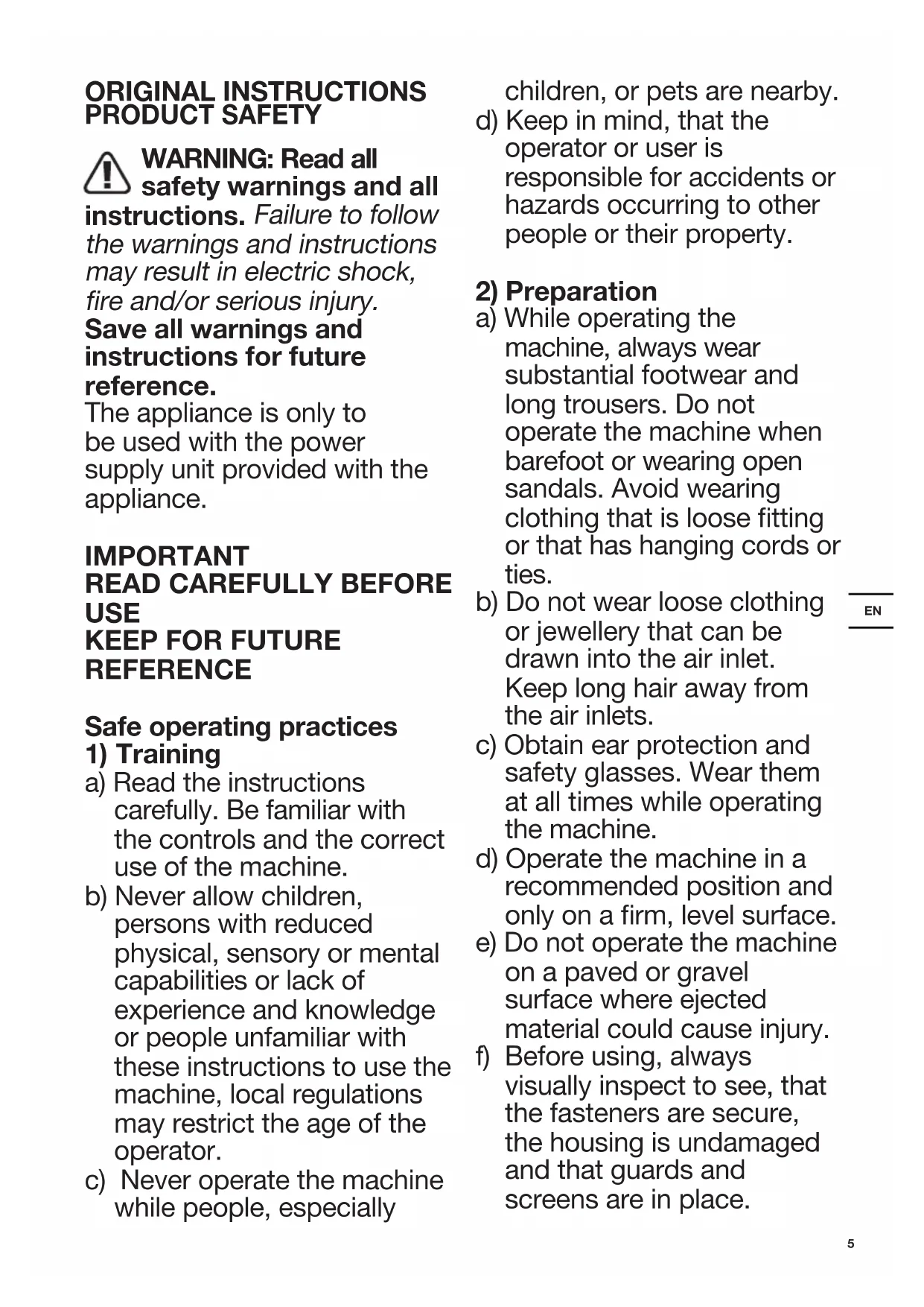
Technical diagram of a handheld air conditioner with numbered parts and exploded view, including labeled connectors and components.COMPONENT LIST
| 1. BLOWER NOZZLE | |
| 2. BLOWER TUBE | |
| 3. FLEXIBLE TUBE | |
| 4. CABLE CLAMP(SEE LIST & FIG.B3) | |
| 5. AIR INTAKE | |
| 6. BATTERY MOUNTING BASE | |
| 7. BATTERY RELEASE BUTTON | |
| 8. BACKPACK HARNESS | |
| 9. CRUISE CONTROL BUTTON | |
| 10. ON/OFF BUTTON | |
| 11. POWER TRIGGER | |
| 12. LED SCREEN | |
| 13. SPEED CONTROL | |
| 14. CABLE | |
| 15. METAL SCRAPER TIP | |
| 16. WARNING SYMBOL | |
| 17. BLUETOOTH SYMBOL | |
| EN | 18. CRUISE CONTROL SYMBOL |
| 19. FRONT HANDLE CLAMP (SEE FIG. C1) | |
| 20. CONTROL HANDLE (SEE FIG.C2) | |
| 21. COUPLER(SEE FIG.B2) | |
| 22. CABLE RING (SEE FIG.C3) | |
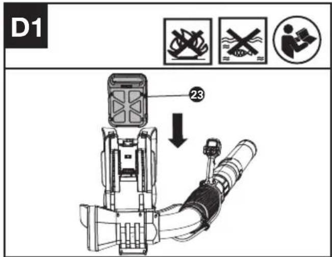
| 23. BATTERY PACK*(SEE FIG.D1) | |
| 24. HOOK (SEE FIG.G) | |
| 25. FLEXIBLE TUBE CLAMP (SEE FIG.G) | |
| 26. SCREW M5*16 FOR SHOULDER BELT & WAIST BELT **(SEE FIG A3,A6) | |
| 27. SCREW PT5*22 FOR CLAMP**(SEE FIG B1,B3) | |
| 28. SCREW PT4*18 FOR HANDLE **(SEE FIG C2) | |
| 29. WRENCH**(SEE FIG A3) |
* Not all the accessories illustrated or described are included in standard delivery. **Please use the screws for the specified positions and the screws & wrench can be found in the transparent bag.
ORIGINAL INSTRUCTIONS PRODUCT SAFETY

WARNING: Read all
safety warnings and all
instructions. Failure to follow the warnings and instructions may result in electric shock, fire and/or serious injury.
Save all warnings and instructions for future reference.
The appliance is only to be used with the power supply unit provided with the appliance.
IMPORTANT
READ CAREFULLY BEFORE USE
KEEP FOR FUTURE REFERENCE
Safe operating practices
1) Training
a) Read the instructions carefully. Be familiar with the controls and the correct use of the machine.
b) Never allow children, persons with reduced physical, sensory or mental capabilities or lack of experience and knowledge or people unfamiliar with these instructions to use the machine, local regulations may restrict the age of the operator.
c) Never operate the machine while people, especially
children, or pets are nearby.
d) Keep in mind, that the operator or user is responsible for accidents or hazards occurring to other people or their property.
2) Preparation
a) While operating the machine, always wear substantial footwear and long trousers. Do not operate the machine when barefoot or wearing open sandals. Avoid wearing clothing that is loose fitting or that has hanging cords or ties.
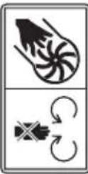
b) Do not wear loose clothing or jewellery that can be drawn into the air inlet. Keep long hair away from the air inlets.
c) Obtain ear protection and safety glasses. Wear them at all times while operating the machine.
d) Operate the machine in a recommended position and only on a firm, level surface.
e) Do not operate the machine on a paved or gravel surface where ejected material could cause injury.
f) Before using, always visually inspect to see, that the fasteners are secure, the housing is undamaged and that guards and screens are in place.
Replace worn or damaged components in sets to preserve balance. Replace damaged or unreadable labels.
3) Operation
a) Before starting the machine, make certain that the feeding chamber is empty.
b) Keep your face and body away from the feed intake opening.
c) Do not allow hands or any other part of the body or clothing inside the feeding chamber, discharge chute, or near any moving part.
d) Keep proper balance and footing at all times. Do not overreach. Never stand at a higher level than the base of the machine when feeding material into it.
e) Always stand clear of the discharge zone when operating this machine.
f) If the machine should start making any unusual noise or vibration, immediately shut off the power source and allow the machine to stop. Remove the battery pack from the machine and take the following steps before restarting and operating the machine:
i) inspect for damage;
ii)replace or repair any damaged parts;
iii)check for and tighten any loose parts.
g) Do not allow processed material to build up in the discharge zone; this may prevent proper discharge and can result in kickback of material through the intake opening.
h) If the machine becomes clogged, shut-off the power source and remove the battery pack from the machine before cleaning debris.
i) Never operate the machine with defective guards or shields, or without safety devices.
j) Keep the power source clean of debris and other accumulations to prevent damage to the power source or possible fire.
k) Do not transport this machine while the power source is running.
I) Always disconnect the machine from the power supply (e.g. remove the battery pack from the machine)
-whenever you leave the machine,
-before clearing blockages or unclogging chute,
-before checking, cleaning or working on the machine.
m) Avoid using the machine in bad weather conditions
especially when there is a risk of lightning.
4) Maintenance and storage
a) keep all nuts, bolts and screws tight to be sure the appliance is in safe working condition.
b) Replace worn or damaged parts.
c) Use only genuine replacement parts and accessories.
d) Store the machine in a dry place out of the reach of children.
e) When the machine is stopped for servicing, inspection, or storage, or to change an accessory, shut off the power source, disconnect the machine from the supply and make sure that all moving parts are come to a complete stop. Allow the machine to cool before making any inspections, adjustments, etc. Maintain the machine with care and keep it clean.
f) Store the machine in a dry place out of the reach of children.
g) Always allow the machine to cool before storing.
h) Never attempt to override the interlocked feature of the guard.
SAFETY WARNINGS FOR BATTERY PACK
a) Do not dismantle, open or shred cells or battery pack.
b) Do not short-circuit a battery pack. Do not store battery packs haphazardly in a box or drawer where they may short-circuit each other or be short-circuited by conductive materials. When battery pack is not in use, keep it away from other metal objects, like paper clips, coins, keys, nails, screws or other small metal objects, that can make a connection from one terminal to another. Shorting the battery terminals together may cause burns or a fire.
c) Do not expose battery pack to heat or fire. Avoid storage in direct sunlight.
d) Do not subject battery pack to mechanical shock.
e) In the event of battery leaking, do not allow the liquid to come into contact with the skin or eyes. If contact has been made, wash the affected area with copious amounts of water and
seek medical advice.
f) Keep battery pack clean and dry.
g) Wipe the battery pack terminals with a clean dry cloth if they become dirty.
h) Battery pack needs to be charged before use. Always refer to this instruction and use the correct charging procedure.
i) Do not maintain battery pack on charge when not in use.
j) After extended periods of storage, it may be necessary to charge and discharge the battery pack several times to obtain maximum performance.
k) Recharge only with the charger specified by Kress. Do not use any charger other than that specifically provided for use with the equipment.
I) Do not use any battery pack which is not designed for use with the equipment.
m) Keep battery pack out of the reach of children.
n) Retain the original product literature for future reference.
o) Remove the battery from the equipment when not
in use.
p) Dispose of properly.
q) Do not use battery packs of different manufacture, size or type.
r) Keep the battery away from microwaves and high pressure
User manual requirements for wireless product
a) Operation of this device is subject to the following two conditions:
(1) This device may not cause harmful interference, and
(2) this device must accept any interference received, including interference that may cause undesired operation.
b) Caution: Changes or modifications to this unit not expressly approved by the party responsible for compliance could void the user's authority to operate the equipment.
c) NOTE: This equipment generates, uses and can radiate radio frequency energy and, if not installed and used in accordance with the instructions, may cause harmful interference to radio communications. However, there is no guarantee that interference will not occur in a particular installation. If
this equipment does cause harmful interference to radio or television reception, which can be determined by turning the equipment off and on, the user is encouraged to try to correct the interference by one or more of the following measures:
- Reorient or relocate the receiving antenna.
- Increase the separation between the equipment and receiver.
- Connect the equipment into an outlet on a circuit different from that to which the receiver is connected.
- Consult the dealer or an experienced radio/TV technician for help.
SYMBOL
 | Read the operator's manual |
 | Warning |
 | Wear ear protection |
 | Wear eye protection |
| Double insulation | |
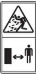 | Keep bystanders away |
 | Warning of hazard |
 | Remove battery from the socket before carrying out any adjustment, servicing or maintenance. |
 | Batteries may enter water cycle if disposed improperly, which can be hazardous for ecosystem. Do not dispose of waste batteries as unsorted municipal waste. |
 | Do not burn |
 | Li-lon battery. This product has been marked with a symbol relating to 'separate collection' for all battery packs and battery pack. It will then be recycled or dismantled in order to reduce the impact on the environment. Battery packs can be hazardous for the environment and for human health since they contain hazardous substances. |
 | Waste electrical products must not be disposed of with household waste. Please recycle where facilities exist. Check with your local authorities or retailer for recycling advice. |
NOTE: Before using the tool, read the instruction book carefully.
BEFORE OPERATION:
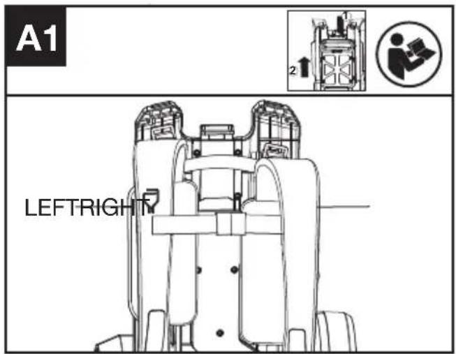
Assemble the harness belt to the harness frame.(Applied when you need to reassemble the harness after washing) Ensure that the shoulder strap with hook is in the left position as shown.(See Fig A1)
text_image
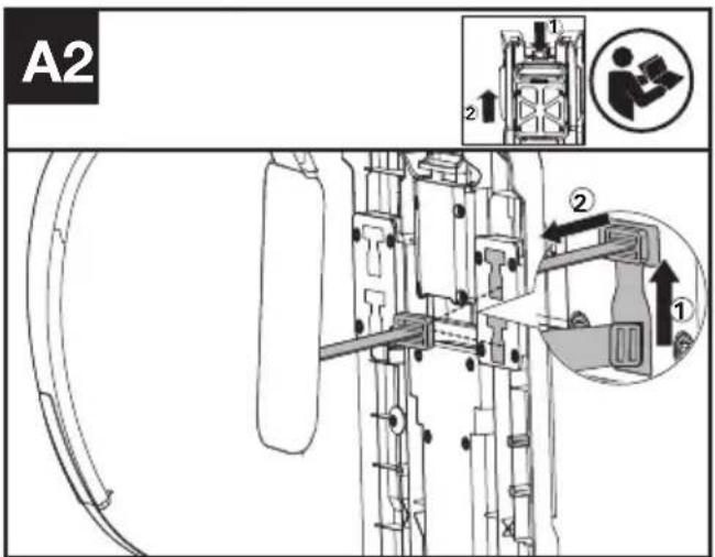
A1 LEFTRIGHTAttach the shoulder belt to the frame(See Fig A2,A3).
text_image
A2 1 2 ① ② ②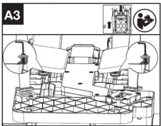
text_image
A3 1 2 ① ②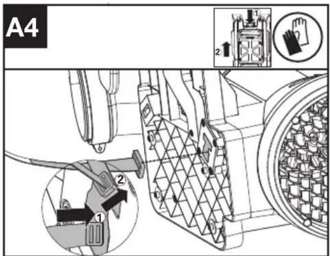
text_image
A4 1 2 ① ②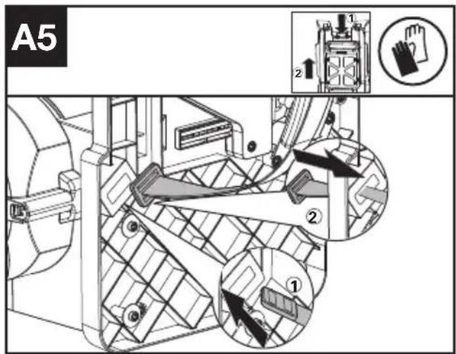
text_image
A5 ① ② ③- Toggle needs to be inserted into the "T" hole, then twisted 90°.(See Fig A2 & A4).
- Fix the strap with screws & washers.(See Fig A3). Screws & washers are in the parts pack.
- Keep the toggle in a flat status and push it through the hole as shown.(See Fig A5).
Note: The harness is designed with two "T" holes in the upper frame to provide two height for your choice. It is suggested to choose upper "T" hole if you are rather tall.
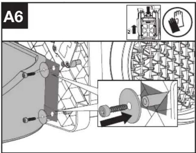
Attach waist belt to the harness frame.( See Fig A6)
text_image
A6 2Fix the waist belt to the frame with screes & washers as shown.(The screws and washers are provided in the parts pack)
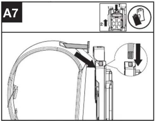
Fix the shoulder toggle into the harness frame.(See A7)
text_image
A7 1 2Insert the shoulder toggle into the harness frame as shown.
Assemble the blower tube
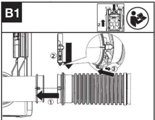
Assemble the flexible tube to the the blower outlet (See Fig. B1)
text_image
B1 ① ② ③- Attach the flexible tube to the blower outlet(①), then put the clamp on the flexible tube(②);
- Fix the clamp with screws as shown(③).
Note: Screw tightening torque value should be set between 10.6 in·lb(1.2Nm) and 14.2 in·lb(1.6Nm).
Assemble the blower tube, coupler and flexible tube. (See Fig. B2,B3)
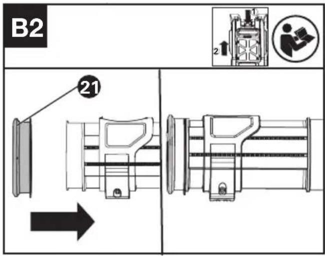
text_image
B2 21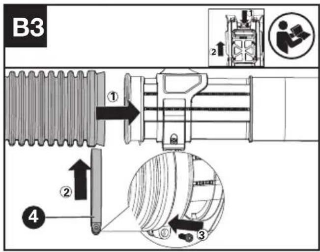
text_image
B3 ① ② ③ ④- Attach the coupler (21) to the end of the blower tube.(See Fig.B2);
- Insert the coupler, together with the blower tube, into the flexible tube.(See Fig B3 ①). Then put the clamp on the end of the flexible tube as shown(See Fig B3 ②);
- Tighten the clamp with screws as shown.(See Fig B3 3).
Note: Screw tightening torque value should be set between 10.6 in·lb(1.2Nm) and 14.2 in·lb(1.6Nm).
Ffit an auxiliary nozzle(See Fig B4)
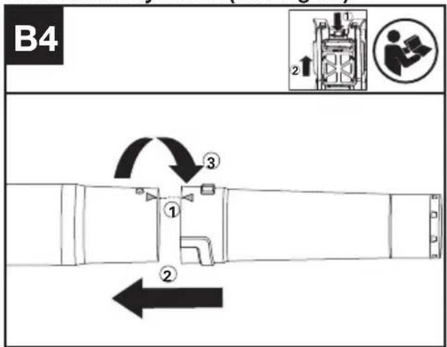
text_image
B4 ① ② ③- Match the "△" between the blower tube and blower nozzle(①);
- Push the nozzle onto the blower tube along the thread(2).
- Twist the blower nozzle in the direction shown to lock in the blower nozzle(3).
Assemble the control handle(See Fig C1,C2,C3)
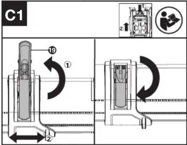
text_image
C1 19 ① 2 2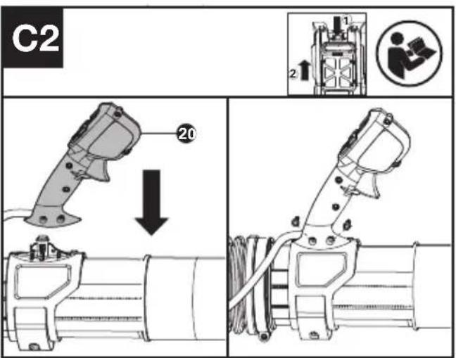
text_image
C2 20 1 2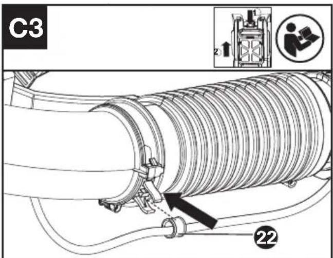
text_image
C3 2 22- Open the front handle clamp and move it to the desired place, then close the front handle clamp as shown(See Fig C1).
- Assemble the control handle with screws as
shown.(See Fig C2). Note:Screw tightening torque value should be set between 10.6 in·lb(1.2Nm) and 14.2 in·lb(1.6Nm). 3. Put the cable coupler into flexible tube clamp.(See Fig.C3)
OPERATION
Install /Remove the battery(See Fig. D1 D2)
text_image
D1 23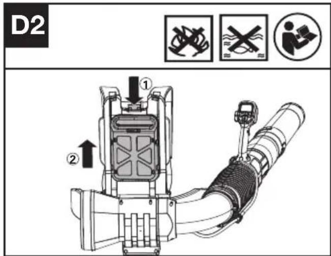
text_image
D2 ① ②- Battery Installation: Push the battery along the slot.
- Battery Removal: Press the release button and pull the battery out.
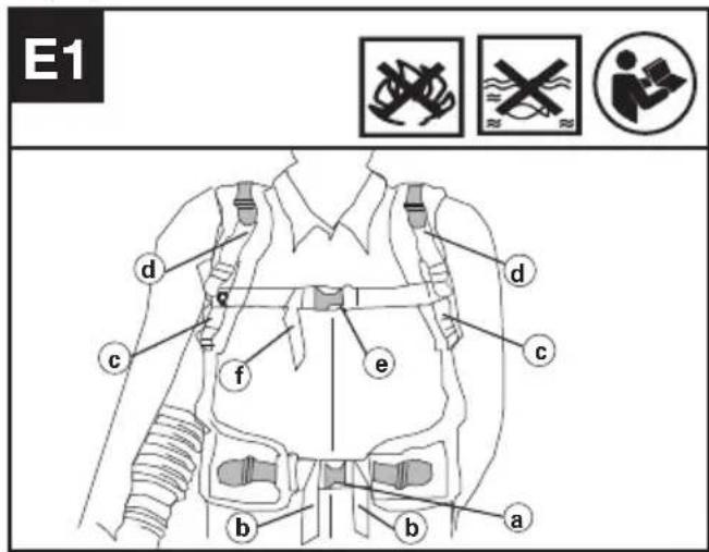
Putting the harness on the product.(See Fig E1,E2)
text_image
E1 d c f e b a b c d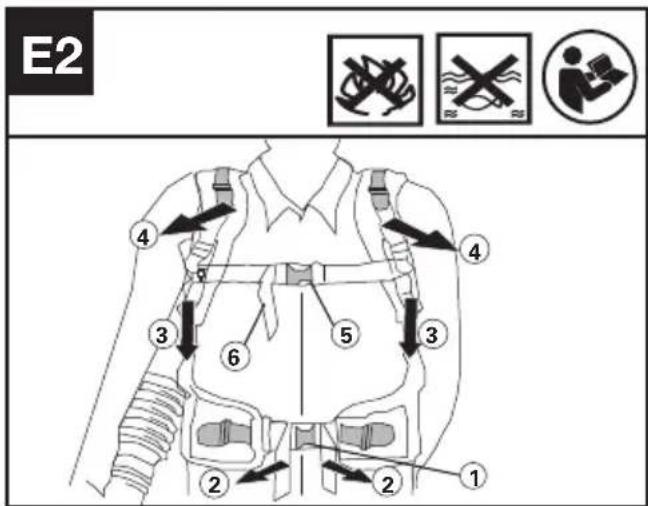
text_image
E2 ① ② ③ ④ ⑤ ⑥ ⑦ ⑧- Fasten the waist buckle(a). Adjust the length of waist straps(b) in order to make sure it is securely positioned in your hips.(See Fig E2 step ① ②)
- Tighten the arm straps(c)and shoulder straps(d). Remember to leave a samll gap over the shoulder to distribute weight of battery over shoulders to balance weight.(See Fig E2 step 3④)
3.Fasten the chest buckle(e) and adjust chest straps(f) before work. (See Fig E2 step 5 6)
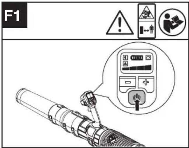
To start (See Fig. F1)
text_image
F1 ! ▲ ▲ ← ← ← ← ↓ → ← ← ← ← ← ← ← ← ← ← ← ← ← ← ← ← ← ← ← ← ← ← ← ← ← ← ← ← ← ← ← ← ← ← ← ← ← ← ← ← ← ← ← ← ← ← ← ← ← ← →- Press the 📁 for 0.5 seconds start the product.
Note: When pressing the power button, please do not press the trigger, otherwise it will result in a fault alarm.
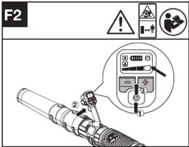
Adjust the speed control (See Fig. F2)
text_image
F2 1 2 3- Press on/off button to activate the blower, then press the trigger to operate the blower. Press +/- to choose proper level of air force. The blower will reach the MAX speed when the four lights are illuminated.
Push the Cruise control button to set the selected airflow, the 📞 will light up(See Fig F3)
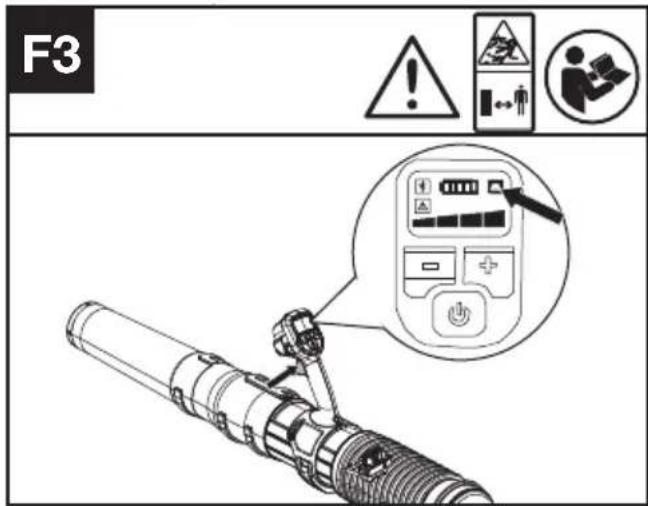
- Press on/off button to activate the blower, then press the trigger to operate the blower. Press the cruise control button and symbol " lights up, then the blower will be at the current speed even if you release the trigger.
- You could press trigger to have bigger air force within the chosen level limit and release the trigger, the speed will return to the cuise speed. Press cruise control button to deactivate the cruise function when needed
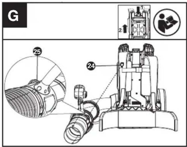
The application of hook on the harness. (See Fig G)
text_image
G 25 24 1 2In order to save space when not used, just hang the blower coupler to the hook on the harness.
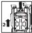
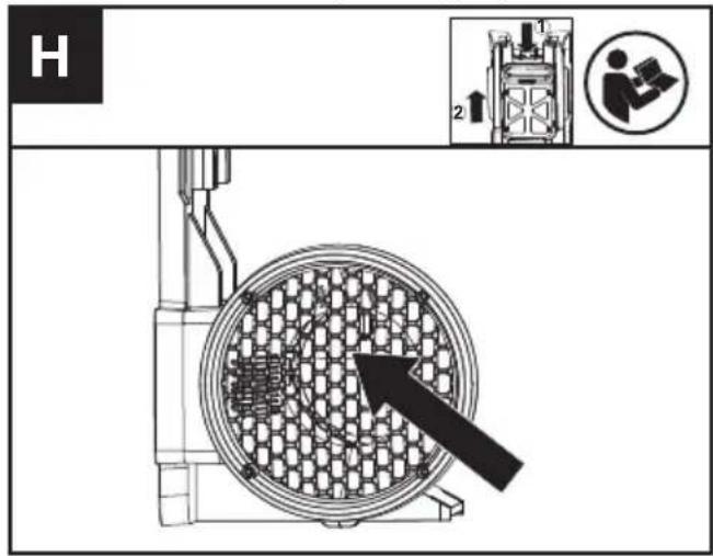
Check the air intake(See Fig. H)
text_image
H 1 2- Check the air intake frequently to ensure that the intake is not be blocked.
- If the intake is blocked, please stop the blower firstly and clear the unwanted material.

WARNING! Make sure to remove the battery before check and clear the blower.
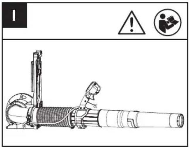
Export static electricity (See Fig. I)
text_image
Technical diagram of a mechanical device with warning symbols and labeled parts, including warning triangle and person icon.Warning – Using the blower in extremely cold and dry conditions may lead to a buildup of static electricity that can cause shocks to the user. To reduce the risk, ensure that there is skin contact to the grounding strap(a) on the handle.
TRANSPORTATION
Transporting the blower
- Switch off the blower and remove the battery.
- When transporting your blower by hand, hang the blower to the hook on the harness and move it to the destination.
Transporting the battery
- Ensure the battery is in a safe condition.
- Use non-conductive packaging when transporting the battery.
- The contained Li-Ion batteries are subject to the dangerous goods legislation requirements.
Transport batteries only when the battery housing is undamaged. Pack up the batteries in such a manner that cannot move around in the packaging.
CLEANING
- Do not use aggressive detergents or solvents. Clean the machine after use with a damp cloth dipped in mild detergent.
- Keep battery connection free of dirt and debris, and clean with a soft and dry brush or cloth.
- Do not spray water onto the motor and electrical components.
- Do not use pressure washer to clean your machine.
- Please disassemble the harness carefully when need to clean the harness belt and reassemble before operation.
STORAGE
- Remove the battery pack from the blower before storage.
- Store the blower and the battery in a dry and secure place that is inaccessible to children and other unauthorized people. Remove the attachment if no use for a long time.
- Store the battery only within a temperature range between 41°F (5°C) and 77°F (25°C). As an example, do not leave the battery in the car in summer time.
- Clean the exterior of the machine thoroughly using a soft brush and cloth. Do not use water, solvents or polishes. Remove all grass and debris, especially from the ventilation slots.
- Store the machine in a dry place. Do not place other objects on top of the machine.
- Once got wet in the rain during operation, the machine and the battery pack should be dried before storing or charging. Remove the battery and reinsert it if the machine fails to turn on.
For Battery tools
The recommended ambient temperature range for discharging is -4^ 113^ ( -20^ 45^ ).
The recommended ambient temperature range for the charging system during charging is 23^ F\~113° (-5°C\~45°C).
TROUBLESHOOTING
The following table gives problems and actions that you can perform if your machine does not operate correctly.

WARNING: Switch the machine off and remove the battery prior to any troubleshooting.
Blower
| Problems Possible | Causes Corrective Action | |
| Battery indicator LED flashing | Low battery voltage. Charge the battery. | |
| Red error LED flashing Temperature | erature issue. Remove the battery. | Let the machine cool down or warm up. |
| The product does not start Deris in the battery connectors. | Clean the battery connectors with compressed air or a soft brush. | |
| Other problems Contact Service Agent. | ||
| The product stops during usage. | The battery is not fully inserted to the machine. | Insert the battery fully. |
| Potential electrical issue. Contact Service Agent. | ||
| Excessive vibrations/ noise. | The air intake screen is blocked | Remove the battery;Open the air intake and clear the unwanted materials away. |
| Cutting attachment issue. Machine defective. | Replace cutting attachment.Contact Service Agent. | |
BATTERY
| Problems Possible | Causes Corrective Action | |
| Error LED lit The battery is discharged | Charge the battery. If battery fails to charge, contact your Service Agent. | |
| Temperature issue. Use the battery in surroundings where temperatures are between -4°F to 113°F (-20°C to 45°C) for discharge. | ||
| Others | Contact your Service Agent. |
TECHNICAL DATA
Type Designation: KC500 KC500.X (5 -designation of machinery, representative of Cordless Blower)
| KC500 KC500.X ** | |
| Voltage | 60 V --- MAX *** |
| Motor type | Brushless |
| Air force | 35N |
| Air volume | 1529 m3/h |
| Air speed | 85m/s |
| Degree of protection | IPX4 |
| Machine Weight (Bare tool) | 6.9Kg |
** X may be followed by one or two characters. All models are the same except model number and trademark. The suffix in models may be number from "1" to "999" or English letter "A" to "Z" or "M1" to "M9" which means different package or the various of accessories packed in the package.
*** Voltage measured without workload. Initial battery voltage reaches maximum of 60 volts. Nominal voltage is 54 volts.
SUGGESTED BATTERIES AND CHARGERS
| Battery Capacity | Charger Amperage | |||
| EN | KAC804 4.0 Ah | KAC840 30 A | ||
| KAC810 11.0 Ah |
We recommend that you purchase your accessories from the same Dealer that sold you the tool. Refer to the accessory packaging for further details. Your Dealer can assist you and offer advice.
TECHNICAL DATA FOR BATTERY PACK (OPTIONAL)
| Frequency bands for Bluetooth | 2400-2483.5 MHz |
| Maximum Transmitted Power for Bluetooth | 8 dBm |
NOISE DATA
| A weighted sound pressure L | _pA =79.5dB(A) |
| K_pA | 3.0 dB(A) |
| A weighted sound power L | _WA = 96.2dB(A) |
| K_wA | 3.0 dB(A) |
| Wear ear protection. |
VIBRATION INFORMATION
| Typical weighted vibration a | _h < 2.5 m/s^2 |
| Uncertainty | K=1.5m/s^2 |
The declared vibration total value may be used for comparing one tool with another, and may also be used in a preliminary assessment of exposure.

WARNING: The vibration emission value
during actual use of the power tool can differ
from the declared value depending on the ways in which the tool is used dependant on the following examples and other variations on how the tool is used:
How the tool is used.
The tool being in good condition and well maintained
Using the correct accessory for the tool and ensuring it is sharp and in good condition.
The tightness of the grip on the handles and if any anti vibration accessories are used.
And the tool is being used as intended by its design and these instructions.
This tool may cause hand-arm vibration syndrome if its use is not adequately managed.

WARNING: To be accurate, an estimation
of exposure level in the actual conditions
of use should also take account of all parts of the operating cycle such as the times when the tool is switched off and when it is running idle but not actually doing the job. This may significantly reduce the exposure level over the total working period.
Helping to minimise your vibration exposure risk.
Maintain this tool in accordance with these instructions and keep well lubricated (where appropriate)
If the tool is to be used regularly then invest in anti vibration accessories.
Plan your work schedule to spread any high vibration tool use across a number of days.
DECLARATION OF CONFORMITY
We,
Positec Germany GmbH
Postfach 32 02 16, 50796 Cologne, Germany
On behalf of Positec declare that the product,
Description Battery-operated Blower
Type KC500 KC500.X (5 - designation of machinery, representative of battery-operated Blower)
Function blowing and picking up debris into a debris collector
Complies with the following Directives:
2006/42/EC, 2014/30/EU,
2011/65/EU&(EU)2015/863,
2000/14/EC amended by 2005/88/EC
2000/14/EC amended by 2005/88/EC:
- Conformity Assessment Procedure as per Annex V
- Measured Sound Power Level 96.2dB(A)
- Declared Guaranteed Sound Power Level 99dB(A)
Standards conform to
EN 60335-1, EN 50636-2-100, EN 62233, EN ISO
3744, EN 55014-1, EN 55014-2
The person authorized to compile the technical file, Name Marcel Filz
Address Positec Germany GmbH
Postfach 32 02 16, 50796 Cologne, Germany

text_image
M C E2022/12/16
Allen Ding
Deputy Chief Engineer, Testing & Certification
Positec Technology (China) Co., Ltd
18, Dongwang Road, Suzhou Industrial
Park, Jiangsu 215123, P. R. China
DECLARATION OF CONFORMITY
We,
Positec (UK & Ireland) Ltd.
PO Box 6242, Newbury, RG14 9LT, UK
On behalf of Positec declare that the product
Description Battery-operated Blower
Type KC500 KC500.X (5 - designation of machinery, representative of battery-operated Blower)
Function blowing and picking up debris into a debris collector
Complies with the following Directives:
Supply of Machinery (Safety) Regulations 2008
Electromagnetic Compatibility Regulations 2016
The Restriction of the Use of Certain Hazardous
Substances in Electrical and Electronic Equipment Regulations
Noise Emission in the Environment by Equipment for Use Outdoors Regulations
- Conformity Assessment Procedure as per SCHEDULE 8
- Measured Sound Power Level 96.2dB(A)
- Declared Guaranteed Sound Power Level 99dB(A)
EN
Standards conform to
BS EN 60335-1, BS EN 50636-2-100, BS EN
62233, BS EN ISO 3744, BS EN 55014-1, BS EN 55014-2
The person authorized to compile the technical file, Name Jim Kirkwood
Address Positec (UK & Ireland) Ltd.,
PO Box 6242, Newbury, RG14 9LT, UK

text_image
M UK CA2022/12/16
Allen Ding
Deputy Chief Engineer, Testing & Certification
Positec Technology (China) Co., Ltd
18, Dongwang Road, Suzhou Industrial
Park, Jiangsu 215123, P. R. China
INHALTSVERZEICHNIS
EINFÜHRUNG....19
KOMPONENTEN 21
text_image
Technical diagram of a handheld air conditioner with numbered parts and labeled connectorsKOMPONENTEN
- GEBLÄSE-DÜSE
- GEBLÄSEROHR
- SCHLAUCHSTÜCK
- KABELSCHELLE (SIEHE LISTE UND ABB. B3)
- LUFTEINLASS
- AKKU-HALTERUNG
- AKKUFREIGABETASTEN
- RUCKSACK-GURTZEUG
- GESCHWINDIGKEITSSTEUER-TASTE
- EIN/AUS-SCHALTER
- BETÄTIGUNG
- LED-BILDSCHIRM
- GESCHWINDIGKEITSKONTROLLE
- KABEL
- METALLRING
- WARN-SYMBOL
- BLUETOOTH-SYMBOL
- GESCHWINDIGKEITSSTEUER-SYMBOL
- VORDERE GRIFFKLEMME (SIEHE ABB. C1)
- STEUERGRIFF (SIEHE ABB. C2)
- ANSCHLUSSSTÜCK (SIEHE ABB. B2)
- KABELRING (SIEHE ABB. C3)
- AKKU*(SIEHE ABB.D1)
- HAKEN (SIEHE ABB. G)
- SCHLAUCHSCHELLE (SIEHE ABB. G)
- SCHRAUBE M5*16 FÜR SCHULTERGURT UND HÜFTGURT ** (SIEHE ABB. A3, A6)
- SCHRAUBE PT5*22 FÜR KLEMME ** (SIEHE ABB. B1, B3)
- SCHRAUBE PT4*18 FÜR GRIFF ** (SIEHE ABB. C2)
- SCHRAUBENSCHLÜSSEL ** (SIEHE ABB. A3)
text_image
A3 1 2 ① ②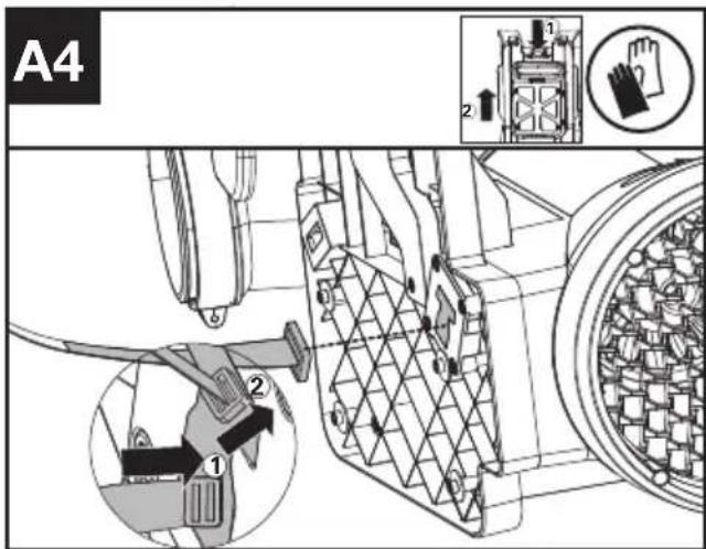
text_image
A4 1 2 1 2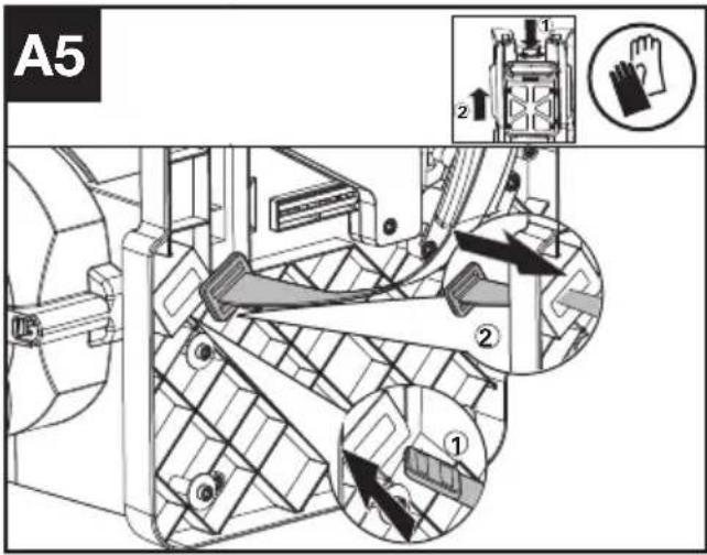
text_image
A5 1 2 ① ② ③text_image
C3 1 2 22text_image
Technical diagram of a mechanical device with warning symbols and safety icons2022/12/16 Allen Ding Deputy Chief Engineer, Testing & Certification Positec Technology (China) Co., Ltd 18, Dongwang Road, Suzhou Industrial Park, Jiangsu 215123, P. R. China
SOMMAIRE
INTRODUCTION 37
LISTE DES COMPOSANTS ....39
NOTICE ORIGINALE 40
ASSEMBLAGE ET FONCTIONNEMENT 46
TRANSPORT 50
NETTOYAGE 50
RANGEMENT ....50
GUIDE DE DÉPANNAGE ....51
CARACTÉRISTIQUES TECHNIQUES ....52
DECLARATION DE CONFORMITE....53
INTRODUCTION
Cher Client,
text_image
Technical diagram of a handheld device with numbered parts and exploded view, including labeled connectors and components.LISTE DES COMPOSANTS
-
BOUCHE DE SOUFFLEUSE
-
TUYAU DE SOUFFLAGE
-
TUBE FLEXIBLE
-
ATTACHE DE TUBE (VOIR LA LISTE ET FIG. B3)
-
PRISE D'AIR
-
BASE DE FIXATION DE LA BATTERIE
-
BOUTONS DE DÉTACHEMENT DU BLOC DE BATTERIE
-
HARNAIS DORSAL
-
BOUTON D'ACTIVATION MAINTENUE
-
COMMUTATEUR MARCHE/ARRÊT
-
GÂCHETTE
-
ÉCRAN LED
-
CONTRÔLE DE LA PUISSANCE
-
CÂBLE
-
EMBOUT DE GRATTAGE EN MÉTAL
-
SYMBOLE D'AVERTISSEMENT
-
SYMBOLE BLUETOOTH
-
SYMBOLE D'ACTIVATION MAINTENUE
-
ATTACHE DE POIGNÉE AVANT (VOIR FIG. C1)
-
POIGNÉE DE COMMANDE (VOIR FIG. C2)
-
COUPLEUR (VOIR FIG. B2)
-
ANNEAU DE CÂBLE (VOIR FIG. C3)
-
PACK BATTERIE*(VOIR FIG.D1)
-
CROCHET (VOIR FIG. G)
-
COLLIER DU TUBE FLEXIBLE (VOIR FIG. G)
-
VIS M5*16 POUR DOSSIÈRE ET BRETELLES** (VOIR FIG A3, A6)
-
VIS PT5*22 POUR COLLIER** (VOIR FIG B1, B3)
-
VIS PT4*18 POUR POIGNÉE**(VOIR FIG C2)
-
CLÉ**(VOIR FIG A3)
NOTICE ORIGINALE SÉCURITÉ DU PRODUIT

text_image
Technical diagram of a mechanical device with warning symbols and safety iconsINFORMATIONS RELATIVES AU BRUIT
INFORMATIONS RELATIVES AUX VIBRATIONS
Deputy Chief Engineer, Testing & Certification
Positec Technology (China) Co., Ltd
18, Dongwang Road, Suzhou Industrial
Park, Jiangsu 215123, P. R. China
INDICE
text_image
Technical diagram of a mechanical device with numbered parts and exploded view, including labeled components and internal components.ELEMENTI DELL'APPARECCHIO
-
UGELLO DEL SOFFIATORE
-
TUBO SOFFIANTE
-
TUBO FLESSIBILE
-
MORSETTO PER CAVO (VEDERE ELENCO E FIG.B3)
-
INGRESSO ARIA
-
BASE DI MONTAGGIO DELLA BATTERIA
-
PULSANTI SGANCIO BATTERIA
-
IMBRACATURA DELLO ZAINO
-
PULSANTE CRUISE CONTROL
-
INTERRUTTORE DI AVVIO/ARRESTO
-
GRILLETTO DI POTENZA
-
SCHERMO LED
-
CONTROLLO DELLA VELOCITÀ
-
CAVO
-
PUNTA DEL RASCHIETTO IN METALLO
-
SIMBOLO DI AVVERTIMENTO
-
SIMBOLO BLUETOOTH
-
SIMBOLO DEL CRUISE CONTROL
-
MORSETTO DELLA MANIGLIA ANTERIORE (VEDERE FIG. C1)
-
MANIGLIA DI CONTROLLO (VEDERE FIG. C2)
-
ACCOPPIATORE (VEDERE FIG. B2)
-
ANELLO CAVO (VEDERE FIG. C3)
-
UNITÀ BATTERIA*(VEDERE FIG.D1)
-
GANCIO (VEDERE FIG.G)
-
MORSETTO PER TUBO FLESSIBILE (VEDERE FIG.G)
-
VITE M5*16 PER CINTURA A TRACOLLA E CINTURA IN VITA **(VEDI FIG. A3, A6)
-
VITE PT5*22 PER MORSETTO**(VEDI FIG B1, B3)
-
VITE PT4*18 PER MANIGLIA **(VEDI FIG. C2)
-
CHIAVE** (VEDI FIG. A3)
ISTRUZIONI ORIGINALI SICUREZZA DEL PRODOTTO

text_image
F1 ! ▲ ▲ ← ← ← ← → → → → → → → → → → → → → → → → → → → → → → → → → → → → → → → → → → → → → → → → → → → → → → → → → → ↑text_image
Technical diagram of a mechanical device with warning symbols and labeled parts, including warning triangle and person icon.Deputy Chief Engineer, Testing & Certification
Positec Technology (China) Co., Ltd
18, Dongwang Road, Suzhou Industrial
Park, Jiangsu 215123, P. R. China
ÍNDICE
text_image
Technical diagram of a handheld air conditioner with numbered parts and component labelstext_image
A3 1 2 ① ②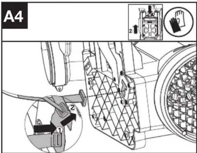
text_image
A4 1 2 3 4 5 6 7 8 9 10 11 12 13 14 15 16 17 18 19 20 21 22 23 24 25 26 27 28 29 30 31 32 33 34 35 36 37 38 39 40 41 42 43 44 45 46 47 48 49 50 51 52 53 54 55 56 57 58 59 60 61 62 63 64 65 66 67 68 69 70 71 72 73 74 75 76 77 78 79 80 81 82 83 84 85 86 87 88 89 90 91 92 93 94 95 96 97 98 99 100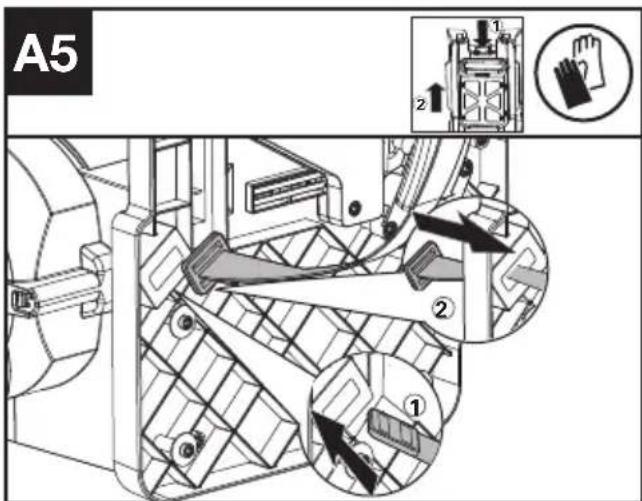
text_image
A5 1 2 ① ②text_image
F3 ! ▲ ▲ ← ← ← ← → → → → → → → → → → → → → → → → → → → → → → → → → → → → → → → → → → → → → → → → → → → → → → → → → → ↑ ↓text_image
Technical diagram of a mechanical device with warning symbols and labeled component 'a'Deputy Chief Engineer, Testing & Certification
Positec Technology (China) Co., Ltd
18, Dongwang Road, Suzhou Industrial
Park, Jiangsu 215123, P. R. China
ÍNDICE
INTRODUÇÃO....89
LISTA DE COMPONENTES....91
MANUAL ORIGINAL....92
text_image
Technical diagram of a mechanical device with numbered parts and exploded view, including labeled components and internal components.text_image
G 25 0 24text_image
Technical diagram of a mechanical device with warning symbols and labeled parts, including warning triangle and person icon.Deputy Chief Engineer, Testing & Certification
Positec Technology (China) Co., Ltd
18, Dongwang Road, Suzhou Industrial
Park, Jiangsu 215123, P. R. China
INHOUDSOPGAVE
INLEIDING....106
DRIE SNELHEIDSINSTELLINGEN ....108
OORSPRONKELIJKE ....109
ASSEMBLAGE EN BEDIENING....115
TRANSPORT....119
REINIGING 119
OPSLAG 120
PROBLEMENOPLOSSEN....120
text_image
Technical diagram of a handheld device with numbered parts and exploded view, including labeled connectors and components.DRIE SNELHEIDSINSTELLINGEN
| 1. BLAASMOND | |
| 2. BLAASPIJP | |
| 3. FLEXIBELE BUIS | |
| 4. KABELKLEM (ZIE LIJST & AFB. B3) | |
| 5. LUCHTINLAAT | |
| 6. ACCUMONTAGESTEUN | |
| 7. KNOP OM BATTERIJ LOS TE MAKEN | |
| 8. RUGZAKHARNAS | |
| 9. CRUISECONTROL-KNOP | |
| 10. AAN/UIT-SCHAKELAAR | |
| 11. STROOMSCHAKELAAR | |
| 12. LED-SCHERM | |
| 13. SNELHEIDSREGELAAR | |
| 14. KABEL | |
| 15. PUNT VAN METALEN KRABBER | |
| 16. WAARSCHUWINGSSYMBOOL | |
| 17. BLUETOOTH-SYMBOOL | |
| NL | 18. CRUISECONTROL-SYMBOOL |
| 19. VOORSTE HANDGREEPKLEM (ZIE AFB. C1) | |
| 20. BEDIENINGSHENDEL(ZIE AFB. C2) | |
| 21. KOPPELING (ZIE AFB. B2) | |
| 22. KABELRING (ZIE AFB. C3) | |
| 23. ACCUPACK*(ZIE AFB.D1) | |
| 24. HAAK (ZIE AFB.G) | |
| 25. FLEXIBELE BUISKLEM (ZIE AFB.G) | |
| 26. SCHROEF M5*16 VOOR SCHOUDERRIEM EN HEUPRIEM** (ZIE AFB. A3, A6) | |
| 27. SCHROEF PT5*22 VOOR KLEM** (ZIE AFB. B1, B3) | |
| 28. SCHROEF PT4*18 VOOR HANDGREEP** (ZIE AFB. C2) | |
| 29. MOERSLEUTEL** (ZIE AFB. A3) |
text_image
A5 1 2 ① ② ③text_image
Technical diagram of a mechanical device with warning symbols and labeled parts, including warning sign, warning symbol, and safety icons.Deputy Chief Engineer, Testing & Certification
Positec Technology (China) Co., Ltd
18, Dongwang Road, Suzhou Industrial
Park, Jiangsu 215123, P. R. China
TARTALOMJEGYZÉK
BEVEZETŐ....123
AZ ALKATRÉSZEK LISTÁJA 125
EREDETI HASZNÁLATI 126
text_image
Technical diagram of a handheld air conditioner with numbered parts and labeled connectors| Remove battery from the socket before carrying out any adjustment, servicing or maintenance. | |
 | Batteries may enter water cycle if disposed improperly, which can be hazardous for ecosystem. Do not dispose of waste batteries as unsorted municipal waste. |
 | Do not burn |
 | Li-lon battery. This product has been marked with a symbol relating to ‘separate collection’ for all battery packs and battery pack. It will then be recycled or dismantled in order to reduce the impact on the environment. Battery packs can be hazardous for the environment and for human health since they contain hazardous substances. |
 | Waste electrical products must not be disposed of with household waste. Please recycle where facilities exist. Check with your local authorities or retailer for recycling advice. |
text_image
A5 1 2 ① ② ③text_image
C3 2 1 22text_image
F1 ! ! ! ← ← ← ← ← ← ← ← ← ← ← ← ← ← ← ← ← ← ← ← ← ← ← ← ← ← ← ← ← ← ← ← ← ← ← ← ← ← ← ← ← ← ← ← ← ← ← ← ← ← ←text_image
Technical diagram of a mechanical device with warning symbols and safety iconsDeputy Chief Engineer, Testing & Certification
Positec Technology (China) Co., Ltd
18, Dongwang Road, Suzhou Industrial
Park, Jiangsu 215123, P. R. China
CUPRINS
INTRODUCERE 141
LISTADE COMPONENTE....143
INSTRUCTIUNI ORIGINALE....144
ASAMBLARE ŞI OPERARE....150
TRANSPORTUL....154
CURĂȚAREA 154
DEPOZITAREA....155
DETECTAREA DEFECTIUNILOR....155
DATE TEHNICE....156
DECLARAȚIE DE CONFORMITATE....157
INTRODUCERE
Stimate Client,
text_image
Technical diagram of a mechanical device with numbered parts and labeled connectors, likely for assembly or maintenance instructions.LISTA DE COMPONENTE
-
DUZĂ DE SUFLANTĂ
-
TUB SUFLANTĂ
-
TUB FLEXIBIL
-
CLEMĂ PENTRU CABLU (A SE VEDEA LISTA ȘI FIG. B3)
-
ADMISIE DE AER
-
BAZĂ DE MONTARE ACUMULATOR
-
BUTON DE ELIBERARE A ACUMULATORULUI
-
HAM DE RUCSAC
-
BUTON PENTRU CONTROLUL VITEZEI ECONOMICE
-
BUTON DE PORNIRE/OPRIRE
-
BUTON DE PUTERE
-
ECRAN LED
-
CONTROLUL VITEZEI
-
CABLU
-
VÂRF PENTRU ÎNDEPĂRTAREA METALELOR
-
SIMBOL DE AVERTIZARE
-
SIMBOL BLUETOOTH
-
SIMBOL PENTRU CONTROLUL VITEZEI ECONOMICE
-
CLEMĂ MÂNER FRONTRAL (A SE VEDEA FIG. C1)
-
MÂNER DE COMANDĂ (A SE VEDEA FIG. C2)
-
CUPLĂ (A SE VEDEA FIG. B2)
-
INEL PENTRU CABLU (A SE VEDEA FIG. C3.)
-
ACUMULATOR* (A SE VEDEA FIG.D1)
-
CÂRLIG (A SE VEDEA FIG. G.)
-
CLEMĂ PENTRU TUB FLEXIBIL (A SE VEDEA FIG. G.)
-
ŞURUB M5*16 PENTRU CUREAUA DE UMĂR ȘI CEA DE TALIE ** (A SE VEDEA FIG. A3, A6)
-
ŞURUB PT5*22 PENTRU CLEMÄ** (A SE VEDEA FIG. B1, B3)
-
ŞURUB PT4*18 PENTRU MÂNER ** (A SE VEDEA FIG. C2)
-
CHEIE** (A SE VEDEA FIG. A3)
INSTRUCTIUNI ORIGINALE SECURITATEA PRODUSULUI
text_image
A3 1 2 ① ②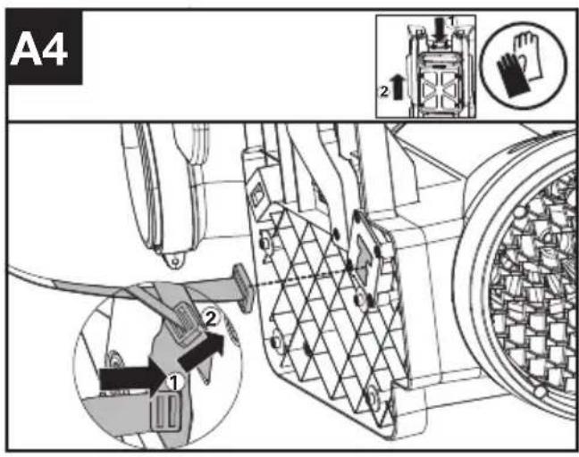
text_image
A4 1 2 2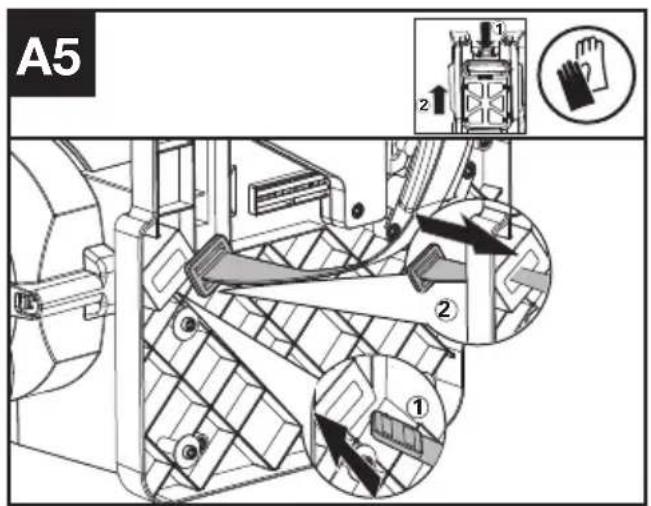
text_image
A5 1 2 ① ② ③text_image
Technical diagram of a mechanical device with warning symbols and labeled parts, including warning triangle and person icon.Deputy Chief Engineer, Testing & Certification
Positec Technology (China) Co., Ltd
18, Dongwang Road, Suzhou Industrial
Park, Jiangsu 215123, P. R. China
SPIS TREŚCI
WPROWADZENIE ....158
LISTA KOMPONENTÓW 160
INSTRUKCJA ORYGINALNA....161
MONTAŻ IOBSŁUGA....168
TRANSPORT....172
CZYSZCZENIE....173
PRZECHOWYWANIE....173
ROZWIAZYWANIEPROBLEMÓW....174
DANETECHNICZNE....175
DEKLARACJA ZGODNOŚCI....176
PL
WPROWADZENIE
Drogi kliencie,
text_image
Technical diagram of a handheld air conditioner with numbered parts and exploded view, including labeled connectors and components.LISTA KOMPONENTÓW
text_image
A5 1 2 ① ② ③text_image
B4 ① ② ③ 2↑ ←text_image
C3 2 1 22text_image
Technical diagram of a mechanical device with warning symbols and labeled parts, including a warning triangle and a person icon.Transport akumulatora
Deputy Chief Engineer, Testing & Certification
Positec Technology (China) Co., Ltd
18, Dongwang Road, Suzhou Industrial
Park, Jiangsu 215123, P. R. China
OBSAH
ÚVOD....177
SEZNAM KOMPONENT 179
PŮVODNÍ NÁVOD K POUŽÍVÁNÍ 180
SESTAVENÍ A POUŽÍVÁNÍ 186
PŘEPRAVA....190
ČIŠTĚNÍ......190
SKLADOVÁNÍ 190
HLEDÁNÍZÁVAD....191
TECHNICKÉ ÚDAJE....192
PROHLÁŠENÍ O SHODĚ 193
ÚVOD
Vážený zákazníku,
text_image
Technical diagram of a handheld air conditioner with numbered parts and labeled connectorsSEZNAM KOMPONENT
-
HUBICE FUKARU
-
TRUBICE FUKARU
-
OHEBNÁ TRUBICE
-
KABELOVÁ SVORKA (VIZ SEZNAM A OBR. B3)
-
PŘÍVOD VZDUCHU
-
MONTÁŽNÍ ZÁKLADNA BATERIE
-
ZÁPADKA JEDNOTKY BATERIÍ
-
POSTROJ ZÁDOVÉHO NOSIČE
-
TLAČÍTKO TEMPOMATU
-
SPÍNAČ ZAPNUTO/VYPNUTO
-
SPOUŠT
-
LED OBRAZOVKA
-
REGULACE OTÁČEK
-
KABEL
-
KOVOVÁ ŠPIČKA ŠKRABKY
-
VÝSTRAŽNÝ SYMBOL
-
BLUETOOTH SYMBOL
-
SYMBOL TEMPOMATU
-
SVORKA PŘEDNÍ RUKOJETI (VIZ OBR. C1)
-
OVLÁDACÍ RUKOJEŤ (VIZ OBR. C2)
-
SPOJKA (VIZ OBR. B2)
-
KABELOVÝ KROUŽEK (VIZ OBR. C3)
-
AKUMULÁTOR* (VIZ OBR.D1)
-
HÁČEK (VIZ OBR.G)
-
SVORKA OHEBNÉ TRUBICE (VIZ OBR.G)
-
ŠROUB M5*16 K RAMENNÍMU POPRUHU & BEDERNÍMU POPRUHU ** (VIZ OBR. A3, A6)
-
ŠROUB PT5*22 KE SVORCE ** (VIZ OBR. B1, B3)
-
ŠROUB PT4*18 K RUKOJETI ** (VIZ OBR. C2)
-
KLÍČ NA MATICE ** (VIZ OBR. A3)
text_image
Technical diagram of a mechanical device with warning symbols and labeled parts, including warning triangle and person icon.INFORMACE TÝKAJÍCÍ SE HLUČNOSTI
Deputy Chief Engineer, Testing & Certification
Positec Technology (China) Co., Ltd
18, Dongwang Road, Suzhou Industrial
Park, Jiangsu 215123, P. R. China
OBSAH
ÚVOD....194
ZOZNAM SÚČASTÍ....196
PÔVODNÝ NÁVOD NA POUŽITIE.... 197
MONTÁŽA OBSLUHA....203
PREPRAVA....207
ČISTENIE....207
SKLADOVANIE 208
ODSTRAŇOVANIE PROBLÉMOV....208
TECHNICKÉ ÚDAJE....209
VYHLÁSENIE O ZHODE....210
SK
ÚVOD
Vážený zákazník,
text_image
Technical diagram of a handheld air conditioner with numbered parts and labeled connectorsZOZNAM SÚČASTÍ
| 1. DÝZA FÚKAČA | |
| 2. TRUBICA FUKÁRA | |
| 3. PRUŽNÁ RÚRA | |
| 4. SVORKA LANKA (POZRITE SI ZOZNAM A OBR. B3) | |
| 5. PRÍVOD VZDUCHU | |
| 6. MONTÁŽNA ZÁKLADŇA BATÉRIE | |
| 7. ZÁPADKA JEDNOTKY BATÉRIÍ | |
| 8. POSTROJ BATOHA | |
| 9. TLAČIDLO TEMPOMATU | |
| 10. SIEŤOVÝ VYPÍNAČ ON/OFF | |
| 11. VYPÍNAČ NAPÁJANIA | |
| 12. LED OBRAZOVKA | |
| 13. REGULÁCIA RÝCHLOSTI | |
| 14. LANKO | |
| 15. HROT KOVOVEJ ŠKRABKY | |
| 16. VÝSTRAŽNÁ ZNAČKA | |
| 17. ZNAČKA BLUETOOTH | |
| SK | 18. ZNAČKA TEMPOMATU |
| 19. SVORKA PREDNEJ RUKOVÄTE (POZRITE SI OBR. C1) | |
| 20. RIADIACA RUKOVÄŤ (POZRITE SI OBR. C2) | |
| 21. SPOJKA (POZRITE SI OBR. B2) | |
| 22. CIEVKA NA LANKO (POZRITE SI OBR. C3) | |
| 23. JEDNOTKA BATÉRI* (POZRITE SI OBR.D1) | |
| 24. HÁČIK (POZRITE SI OBR. G) | |
| 25. PRUŽNÁ RÚRA (POZRITE SI OBR. G) | |
| 26. SKRUTKA M5*16 PRE RAMENNÝ PÁS A OPASOK** (POZRITE SI OBR. A3, A6) | |
| 27. SKRUTKA PT5*22 PRE SVORKU (POZRITE SI OBR. B1, B3) | |
| 28. SKRUTKA PT4*18 PRE RUKOVÄŤ ** (POZRITE SI OBR. C2) | |
| 29. KLŮČ (POZRITE SI OBR. A3) | |
text_image
A5 1 2 ① ② ③text_image
F1 ! ▲ ▲ ← ← ← ← ↓ → ← ← ← ← ← ← ← ← ← ← ← ← ← ← ← ← ← ← ← ← ← ← ← ← ← ← ← ← ← ← ← ← ← ← ← ← ← ← ← ← ← ← ← ← ← ← ← ← ← ← →text_image
Technical diagram of a mechanical device with warning symbols and labeled parts, including warning triangle and person icon.Deputy Chief Engineer, Testing & Certification
Positec Technology (China) Co., Ltd
18, Dongwang Road, Suzhou Industrial
Park, Jiangsu 215123, P. R. China
KAZALO VSEBINE
UVOD....211
SESTAVNI DELI....213
IZVIRNA NAVODILA 214
SESTAVLJANJE IN NAČIN UPORABE....220
PREVOZ....224
ČIŠČENJE 224
SHRANJEVANJE 225
ODPRAVLJANJE NAPAK....225
TEHNIČNI PODATKI....226
IZJAVA O SKLADNOSTI....227
UVOD
Spoštovana stranka,
text_image
Technical diagram of a handheld air conditioner with numbered parts and exploded view, including labeled connectors and components.SESTAVNI DELI
-
ŠOBA PUHALNIKA
-
CEVI PUHALNIKA
-
GIBKA CEV
-
KABELSKA OBJEMKA (GLEJ SEZNAM IN SLIKO B3)
-
DOVOD ZRAKA
-
PRITRDILNA PLOŠČA ZA BATERIJO
-
GUMB ZA SPROSTITEV AKUMULATORJA
-
PAS NAHRBTNIKA
-
GUMB ZA TEMPOMAT
-
STIKALO ZA VKLOP/IZKLOP
-
SPROŽILEC ZAGONA
-
LED ZASLON
-
KRMILNIK HITROSTI
-
KABEL
-
KONICA KOVINSKEGA OBROČA
-
OPOZORILNI SIMBOL
-
SIMBOL BLUETOOTH
-
SIMBOLA ZA TEMPOMAT
-
OBJEMKA SPREDNJEGA ROČAJA (GLEJ SLIKO C1)
-
KRMILNA ROČICA (GLEJ SLIKO C2)
-
SPOJKA (GLEJ SLIKO B2)
-
KABELSKI OBROČ (GLEJ SLIKO C3)
-
AKUMULATOR* (GLEJ SLIKO.D1)
-
KAVELJ (GLEJ SLIKO.G)
-
OBJEMKA ZA GIBKO CEV (GLEJ SLIKO.G)
-
VIJAK M5*16 ZA RAMENSKI PAS IN PAS ZA OKOLI TREBUHA ** (GLEJ SLIKI A3,A6)
-
VIJAK PT5*22 ZA OBJEMKO ** (GLEJ SLIKI B1,B3)
-
VIJAK PT4*18 ZA ROČAJ ** (GLEJ SLIKO C2)
-
KLJUČ ** (GLEJ SLIKO A3)
IZVIRNA NAVODILA VARNOST IZDELKA

OPOZORILO Preberite vsa
text_image
A5 1 2 ① ② ③text_image
B4 ① ② ③ ②text_image
G 25 24 9text_image
Technical diagram of a mechanical device with warning symbols and labeled parts, including warning triangle and person icon.Deputy Chief Engineer, Testing & Certification
Positec Technology (China) Co., Ltd
18, Dongwang Road, Suzhou Industrial
Park, Jiangsu 215123, P. R. China
SADRŽAJ
UVOD....228
POPISKOMPONENTI....230
SIGURNOST PROIZVODA....231
SKUPINAI OPERACIJA....237
TRANSPORT....241
ČIŠĆENJE 241
SKLADIŠTENJE 242
OTKLANJANJE POTEŠKOĆA 242
TEHNIČKI PODACI....243
IZJAVA O SUKLADNOSTI....244
HR
UVOD
Poštovani,
text_image
Technical diagram of a handheld air conditioner with numbered parts and labeled connectorsPOPIS KOMPONENTI
| 1. MLAZNICA PUHALA |
| 2. CIJEV PUHALA |
| 3. FLEKSIBILNA CIJEV |
| 4. STEZALJKA ZA KABEL (POGLEDAJTE POPIS I SL. B3) |
| 5. USIS ZRAKA |
| 6. POSTOLJE ZA POSTAVLJANJE BATERIJE |
| 7. GUMB ZA OTPUŠTANJE BATERIJE |
| 8. POJASEVI RUKSAKA |
| 9. GUMB ZA TEMPOMAT |
| 10. GUMB ZA UKLJUČIVANJE/ISKLJUČIVANJE |
| 11. SKLOPKA ZA NAPAJANJE |
| 12. LED ZASLON |
| 13. REGULACIJA BRZINE |
| 14. KABEL |
| 15. VRH METALNOG STRUGAČA |
| 16. SIMBOL UPOZORENJA |
| 17. SIMBOL BLUETOOTH |
| 18. SIMBOL TEMPOMATA |
| 19. STEZALJKA PREDNJE RUČKE (POGLEDAJTE SL. C1) |
| 20. UPRAVLJAČKA RUČKA (POGLEDAJTE SL. C2) |
| 21. SPOJNICA (POGLEDAJTE SL. B2) |
| 22. PRSTEN KABELA (POGLEDAJTE SL. C3) |
| 23. BATERIJSKI MODUL* (POGLEDAJTE SL. D1) |
| 24. KUKA (POGLEDAJTE SL. G) |
| 25. STEZALJKA FLEKSIBILNE CIJEVI (POGLEDAJTE SL. G) |
| 26. VIJAK M5*16 ZA NARAMENICU I POJAS ZA STRUK ** (VIDI SL. A3,A6) |
| 27. VIJAK PT5*22 ZA STEZALJKU** (VIDI SL. B1,B3) |
| 28. VIJAK PT4*18 ZA RUČKU** (VIDI SL. C2) |
| 29. KLJUČ** (VIDI SL. A3) |
* Standardna isporuka ne obuhvaća sav ilustriran ili opisan pribor.
**Koristite vijke za navedene položaje, a vijci i ključ se nalaze u prozirnoj vrećici.
SIGURNOST PROIZVO- DA

UPOZORENJE:
Pročitajte sva
sigurnosna upozorenja i sve upute. Nepoštivanje svih navedenih uputa može rezultirati strujnim udarom, požarom i/ili ozbiljnim ozljedama.
text_image
A5 1 2 ① ② ③- Preklopnik umetnite u "T" otvor, a zatim ga okrenite za 90°. (Pogledajte slike A2 i A4).
- Pričvrstite remen vijcima i podloškama. (Pogledajte sliku A3). Vijci i podloške nalaze se u paketu dijelova.
- Držite kopču u ravnom položaju i gurnite je kroz otvor kako je prikazano. (Pogledajte sliku A5).
text_image
F1 ! Warning ← ← ← ← → → → → → → → → → → → → → → → → → → → → → → → → → → → → → → → → → → → → → → → → → → → → → → → → → → ←- Pritisnite 📣 na 0,5 sekundi da biste pokrenuli proizvod.
text_image
Technical diagram of a mechanical device with warning symbols and labeled parts, including warning triangle and person icon.„Upozorenje – korištenje puhala u ekstremno hladnim i suhim uvjetima može dovesti do nakupljanja statičkog elektriciteta koji može uzrokovati šok kod korisnika. Kako biste smanjili rizik, osigurajte kontakt kože s trakama (a) za uzemljenje na ručki.“
TRANSPORT
Transport puhala
- Isključite puhalo i izvadite bateriju.
- Kada ručno prenosite puhalo, objesite ga na kuku na pojasevima i odnesite ga na odredište.
Transport baterije
- Pobrinite se da je baterija u sigurnom stanju.
- Koristite neprovodljivu ambalažu prilikom transporta baterije.
- Uključene litij-ionske baterije podliježu zahtjevima zakona za transport opasnog tereta. Baterije transportirajte samo ako je kućište baterije neoštećeno. Zapakirajte baterije tako da se ne pomiču unutar ambalaže.
prijČIŠĆENJE
- Nemojte upotrebljavati agresivne deterdžente za čišćenje ni otapala. Očistite stroj nakon uporabe vlažnom krpom umočenom u blagi deterdžent.
- Očistite priključak baterije od prljavštine i krhotina, a zatim ga očistite mekom i suhom četkom ili krpom.
- Nemojte prskati vodu po motoru i električnim komponentama.
- Nemojte koristiti visokotlačni perač za čišćenje stroja.
- Pažljivo rastavite pojas kada trebate očistiti pojas i ponovno sastaviti prije rada.
SKLADIŠTENJE
Deputy Chief Engineer, Testing & Certification
Positec Technology (China) Co., Ltd
18, Dongwang Road, Suzhou Industrial
Park, Jiangsu 215123, P. R. China
INDHOLDSFORTEGNELSE
INTRODUKTION 245
LISTADECOMPONENTES....247
ORIGINAL BRUGSANVISNING....248
SAMLING OG BETJENINGS....253
TRANSPORT....257
RENG∅RING....257
OPBEVARING....257
FEJLFINDING....258
TEKNISK DATA....259
KONFORMITETSERKLÆRING 260
INTRODUKTION
Kære kunde,
text_image
Technical diagram of a mechanical device with numbered parts and exploded view, including labeled components and internal components.text_image
Technical diagram of a mechanical device with warning symbols and labeled parts, including warning triangle and person icon.Deputy Chief Engineer, Testing & Certification
Positec Technology (China) Co., Ltd
18, Dongwang Road, Suzhou Industrial
Park, Jiangsu 215123, P. R. China
SISÄLLYSLUETTELO
JOHDANTO....261
KOMPONENTTILUETTELO 263
ALKUPERÄISET OHJEET 264
ASENNUS & OPERAATIO ....269
KULJETUS 273
PUHDISTUS....273
SÄILYTYS 273
VIANETSINTÄ....274
MELUPÄÄSTÖT 275
VAATIMUSTENMUKAISUUSVAKUUTUS 276
JOHDANTO
Hyvä asiakas,
text_image
Technical diagram of a handheld air conditioner with numbered parts and labeled connectorsKOMPONENTTILUETTELO
-
PUHALLUSSUUTIN
-
PUHALLUSPUTKI
-
TAIPUISA PUTKI
-
JOHTOKIINNIKE (KATSO LISTA JA KUVA B3)
-
ILMANOTTOAUKKO
-
AKUN ASENNUSALUSTA
-
AKUN VAPAUTUSPAINIKE
-
VALJAAT
-
VAKIONOPEUDENSÄÄTÖ-PAINIKE
-
ON/OFF-VIRTAKYTKIN
-
TEHOKYTKIN
-
LED-NÄYTTÖ
-
NOPEUDENSÄÄDIN
-
JOHTO
-
METALLINEN KAAVINKÄRKI
-
VAROITUSSYMBOLI
-
BLUETOOTH-SYMBOLI
-
VAKIONOPEUDENSÄÄTÖ-SYMBOLI
-
ETUKAHVAN LUKITUS (KATSO KUVA C1)
-
OHJAINKAHVA (KATSO KUVA C2)
-
LIITIN (KATSO KUVA B2)
-
JOHTORENGAS (KATSO KUVA C3)
-
AKKU* (KATSO KUVA D1)
-
KOUKKU (KATSO KUVA G)
-
TAIPUISAN PUTKEN KIINNIKE (KATSO KUVA G)
-
RUUVI M5*16 OLKAHIHNALLE JA LANTIOVYÖLLE **(KS. KUVAT A3, A6)
-
RUUVI PT5*22 KIRISTIMEEN **(KS. KUVA B1, B3)
-
RUUVI PT4*18 KAHVAAN **(KATSO KUVA C2)
-
KUUSIOKOL OAVAIN (KATSO KUVA A3)
text_image
A3 1 2 ↑ ① ②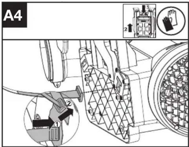
text_image
A4 1 2 3 4 5 6 7 8 9 10 11 12 13 14 15 16 17 18 19 20 21 22 23 24 25 26 27 28 29 30 31 32 33 34 35 36 37 38 39 40 41 42 43 44 45 46 47 48 49 50 51 52 53 54 55 56 57 58 59 60 61 62 63 64 65 66 67 68 69 70 71 72 73 74 75 76 77 78 79 80 81 82 83 84 85 86 87 88 89 90 91 92 93 94 95 96 97 98 99 100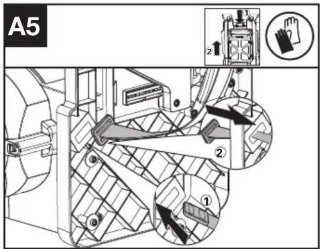
text_image
A5 ① ② ③ ④text_image
F3 ! ! ← ← ← ← ← ← → → → → → → → → → → → → → → → → → → → → → → → → → → → → → → → → → → → → → → → → → → → → → → → → → → ←text_image
G 25 0 24 9text_image
Technical diagram of a mechanical device with warning symbols and labeled parts, including warning triangle and person icon.Deputy Chief Engineer, Testing & Certification
Positec Technology (China) Co., Ltd
18, Dongwang Road, Suzhou Industrial
Park, Jiangsu 215123, P. R. China
INNHOLDFORTEGNELSE
INTRODUKSJON 277
APPARATELEMENTER 279
ORIGINAL DRIFTSINSTRUKS....280
MONTERING OG BRUK....285
TRANSPORT....289
RENGJ∅RING 289
OPPBEVARING....289
FEILS∅KING....290
SAMSVARSERKLÆRING 291
SAMSVARSERKLÆRING 292
INTRODUKSJON
Kjære kunde,
text_image
Technical diagram of a handheld air conditioner with numbered parts and labeled connectorsAPPARATELEMENTER
| 1. BLÅSEDYSE |
| 2. BLÅSERR∅R |
| 3. FLEKSIBELT R∅R |
| 4. KABELKLEMME (SE LISTE OG FIG. B3) |
| 5. LUFTINNTAK |
| 6. MONTERINGSFESTE FOR BATTERIPAKKE |
| 7. BATTERIPAKKE UTL∅SERKNAPPER |
| 8. SELER FOR RYGGBÆRING |
| 9. HASTIGHETSHOLDER-KNAPP |
| 10. PÅ/AV-BRYTER |
| 11. STR∅MUTL∅SER |
| 12. LED-SKJERM |
| 13. HASTIGHETSKONTROLL |
| 14. KABEL |
| 15. METALLSKRAPERTUPP |
| 16. ADVARSELSSYMBOL |
| 17. BLUETOOTH-SYMBOL |
| 18. HASTIGHETSHOLDER-SYMBOL |
| 19. FRONTHÅNDTAKSKLEMME (SE FIG. C1) |
| 20. KONTROLLHÅNDTAK (SE FIG. C2) |
| 21. KOBLING (SE FIG. B2) |
| 22. KABELRING (SE FIG. C3) |
| 23. BATTERIPAKKE* (SE FIG D1) |
| 24. KROK (SE FIG G) |
| 25. FLEKSIBEL R∅RKLEMME (SE FIG G) |
| 26. SKRUE M5*16 FOR SKULDERBELTE OG MIDJEBELTE** (SE FIG A3, A6) |
| 27. SKRUE PT5*22 FOR KLEMME** (SE FIG B1, B3) |
| 28. SKRUE PT4*18 FOR HÅNDTAK** (SE FIG C2) |
| 29. SKIFTEN∅KKEL**(SEE FIG A3) |
Rutiner for trygg bruk 1) TRENING
4) VEDLIKEHOLD OG OPPBEVARING
text_image
F1 ! ! ← ← ← ← ← → → → → → → → → → → → → → → → → → → → → → → → → → → → → → → → → → → → → → → → → → → → → → → → → → → ←text_image
F3 ! ▲ ▲ ← ← ← ← → → → → → → → → → → → → → → → → → → → → → → → → → → → → → → → → → → → → → → → → → → → → → → → → → → ↑ ↓text_image
Technical diagram of a mechanical device with warning symbols and labeled parts, including warning triangle and person icon.Deputy Chief Engineer, Testing & Certification
Positec Technology (China) Co., Ltd
18, Dongwang Road, Suzhou Industrial
Park, Jiangsu 215123, P. R. China
INNEHÅLLSFÖRTECKNING
INTRODUKTION 293
KOMPONENTER 295
BRUKSANVISNING I ORIGINAL....296
MONTERING & HANTERIN....301
TRANSPORT....305
RENGÖRING ....305
FÖRVARING....305
FELSÖKNING....306
TEKNISKA DATA....307
DEKLARATION OM ÖVERENSSTÄMMELSE 308
INTRODUKTION
Bästa kund,
text_image
Technical diagram of a mechanical device with numbered parts and exploded view, including labeled components and internal components.KOMPONENTER
-
BLÅSMUNSTYCKE
-
BLÅSRÖRI
-
FLEXIBELT RÖR
-
KABELKLÄMMA (SE LISTA OCH BILD B3)
-
LUFTINTAG
-
BAS FÖR MONTERING AV BATTERII
-
KNAPPAR FÖR LÖSGÖRANDE AV BATTERIPACKEN
-
RYGGSÄCKSSELE
-
FARTHÅLLARKNAPP
-
TILL/FRÅN-STRÖMBRYTAREN
-
STRÖMAVTRYCKARE
-
LED-SKÄRM
-
HASTIGHETSKONTROLL
-
KABEL
-
SPETS PÅ METALLSKRAPA
-
VARNINGSSYMBOL
-
BLUETOOTH-SYMBOL
-
SYMBOL FÖR FARTHÅLLARE
-
FRÄMRE HANDTAGSKLÄMMA (SE BILD C1)
-
KONTROLLHANDTAG (SE BILD C2)
-
KOPPLARE (SE BILD B3)
-
KABELRING (SE BILD C3)
-
BATTERIPAKET* (SE BILD D1)
-
KROK (SE BILD G)
-
FLEXIBEL SLANGKLÄMMA (SE BILD G)
-
SKRUV M5*16 FÖR AXELREM OCH MIDJEBÄLTE **(SE BILD A3,A6)
-
SKRUV PT5*22 FÖR KLÄMMA**(SE BILD B1,B3)
-
SKRUV PT4*18 FÖR HANDTAG **(SE BILD C2)
-
SKRUVNYCKEL** (SE BILD A3)
BRUKSANVISNING I ORIGINAL PRODUKTSÄKERHET

text_image
F1 ! Warning ← ← ← ← → → → → → → → → → → → → → → → → → → → → → → → → → → → → → → → → → → → → → → → → → → → → → → → → → → ←text_image
G 25 24 9text_image
Technical diagram of a mechanical device with warning symbols and labeled parts, including warning triangle and safety icon.Deputy Chief Engineer, Testing & Certification
Positec Technology (China) Co., Ltd
18, Dongwang Road, Suzhou Industrial
Park, Jiangsu 215123, P. R. China