
1305 AA - Saw SKIL - Free user manual and instructions
Find the device manual for free 1305 AA SKIL in PDF.



| Product Type | Radial Miter Saw |
| Brand | Skil |
| Model | 1305 AA |
| Miter Angle Range | -47° to +47° |
| Bevel Angle Range | 0° to 45° |
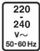
| Power Supply | 230 V ~ 50 Hz |
| Rated Power | 1500 W (estimated) |
| No-Load Speed | 4800 rpm (estimated) |
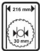
| Blade Diameter | 254 mm (10 inches) |
| Blade Bore | 30 mm (estimated) |
| Weight | 18 kg (estimated) |
| Dimensions (L x W x H) | 600 x 500 x 400 mm (estimated) |
| Max. Cutting Capacity (at 0° miter and 0° bevel) | 90 x 90 mm (estimated) |
| Main Functions | Straight, cross, miter, bevel and compound cuts |
| Safety Devices | Lower guard, upper guard, safety lever, blade brake |
| Dust Extraction System | Integrated dust bag and vacuum port |
| Workpiece Clamping | Integrated adjustable clamp |
| Sliding Guide | Yes, adjustable |
| Maintenance | Regular cleaning of the guard, cooling fins and blade; check lower guard |
| Repairability | Spare parts available through Skil authorized service centers |
| Warranty | According to Skil general conditions |
Frequently Asked Questions - 1305 AA SKIL
User questions about 1305 AA SKIL
0 question about this device. Answer the ones you know or ask your own.
Ask a new question about this device
Download the instructions for your Saw in PDF format for free! Find your manual 1305 AA - SKIL and take your electronic device back in hand. On this page are published all the documents necessary for the use of your device. 1305 AA by SKIL.
USER MANUAL 1305 AA SKIL
natural_image
Technical illustration of a skyl cutting machine with a blade and handle (no text or symbols)GB ORIGINAL INSTRUCTIONS 14
F NOTICE ORIGINALE 19
D ORIGINALBETRIEBSANLEITUNG 25
NL ORIGINELE GEBRUIKSAANWIJZING 31
(S) BRUKSANVISNING I ORIGINAL 37
DK ORIGINAL BRUGSANVISNING 43
(N) ORIGINAL BRUKSANVISNING 48
FIN ALKUPERÄISET OHJEET 54
(E) MANUAL ORIGINAL 59
(P) MANUAL ORIGINAL 65
(Ⅰ) ISTRUZIONI ORIGINALI 72
(H) EREDETI HASZNÁLATI UTASÍTÁS 78
CZ PÜVODNÍM NÁVODEM K POUŽÍVÁNÍ 84
TR ORİJINAL İŞLETME TALİMATI 89
PL INSTRUKCJA ORYGINALNA 95
RU ПОДЛИННИК РУКОВОДСТВА ПО 101
ЭКСПЛУАТАЦИИ
UA ОРИГІНАЛЬНА ІНСТРУКЦІЯ 109
З ЕКСПЛУАТАЦІЇ
GR ΠΡΩΤΟΥΠΟ ΟΔΗΓΙΩΝ ΧΡΗΣΗΣ 115
RO INSTRUCTIUNI DE FOLOSIRE 122
ORIGINALE
BG ОРИГИНАЛНО РЪКОВОДСТВО 128
ЗА ЕКСПЛОАТАЦИЯ
SK PÔVODNÝ NÁVOD NA POUŽITIE 135
HR ORIGINALNE UPUTE ZA RAD 141
SRB ORIGINALNO UPUTSTVO ZA RAD 146
SLO IZVIRNA NAVODILA 152
EST ALGUPÄRANE KASUTUSJUHEND 157
LV ORIGINĀLĀ LIETOŠANAS PAMĀCĪBA 163
(LT) ORIGINALI INSTRUKCIJA 169
(MK) ИЗВОРНО УПАТСТВО ЗА РАБОТА 174
AL UDHËZIMET ORIGJINALE 181
AR دليل الاستعمال 197
FA راهنمای اصلی 193
EAC
www.skil.com

| GB | EU Declaration of conformityMitre saw Article number | We declare under our sole responsibility that the stated products comply with all applicable provisions of the directives and regulations listed below and are in conformity with the following standards.Technical file at:* | |
| F | Déclaration de conformité UEScie à onglets Numéro d'article | Nous déclarons sous notre propre responsabilité que les produits décrits sont en conformité avec les directives, règlements normatifs et normes énumérés ci-dessous.Dossier technique auprès de:* | |
| D | EU-KonformitätserklärungGehrungssäge Sachnummer | Wir erklären in alleiniger Verantwortung, dass die genannten Produkte allen einschlägigen Bestimmungen der nachfolgend aufgeführten Richtlinien und Verordnungen entsprechen und mit folgenden Normen übereinstimmen.Technische Unterlagen bei:* | |
| NL | EU-conformiteitsverklaringVerstekzaag Productnummer | Wij verklaren op eigen verantwoordelijkheid dat de genoemde producten voldoen aan alle desbetreffende bepalingen van de hierna genoemde richtlijnen en verordningen en overeenstemmen met de volgende normen.Technisch dossier bij:* | |
| S | EU-konformitetsförklaringGeringssåg Produktnummer | Vi förklarar under eget ansvar att de nämnda produkterna uppfyller kraven i alla gällande bestämmelser i de nedan angivna direktiven och förordningarnas och att de stämmer överens med följande normer.Teknisk dokumentation.* | |
| DK | EU-overensstemmelseserklæringGeringssav Typenummer | Vi erklærer som eneansvarlige, at det beskrevne produkt er i overensstemmelse med alle gældende bestemmelser i fölgende direktiver og forordninger og opfylder følgende standarder.Tekniske bilag ved:* | |
| N | EU-samsvarserklæringGjæringssag Produktnummer | Vi erklærer under eneansvar at de nevnte produktene er i overensstemmelse med alle relevante bestemmelser i direktivene og forordningene nedenfor og med følgende standarder.Teknisk dokumentasjon hos* | |
| FIN | EU-vaatimustenmukaisuusvakuutusJiirisaha Tuotenumero | Vakuutamme täten, että mainitut tuotteet vastaavat kaikkia seuraavien direktiivien ja asetusten asiaankuuluvia vaatimuksia ja ovat seuraavien standardien vaatimusten mukaisia.Tekniset asiakirjat saatavana.* | |
| E | Declaración de conformidad UESierra de ingletes Número de artículo | Declaramos bajo nuestra exclusiva responsabilidad, que los productos nombrados cumplen con todas las disposiciones correspondientes de las directivas y los reglamentos mencionados a continuación y están en conformidad con las siguientes normas.Documentos técnicos de:* | |
| P | Declaração de conformidade CESerra de mitra Número do produto | Declaramos sob nossa exclusiva responsabilidade que os produtos mencionados cumprem todas as disposições e os regulamentos indicados e estão em conformidade com as seguintes normas.Documentação técnica pertencente à:* | |
| I | Dichiarazione di conformità UETroncatrice radiale Codice prodotto | Dichiariamo sotto la nostra piena responsabilità che i prodotti indicati sono conformi a tutte le disposizioni pertinenti delle direttive e dei regolamenti elencati di seguito, nonché alle seguenti normative.Documentazione tecnica presso:* | |
| H | EU konformitási nyilatkozatGérvágó fűrész Cikkszám | Egyedüli felelőséggel kijelentjük, hogy a megnevezett termékek megfelelnek az alábbiakban felsorolásra kerülő irányelvek és rendeletek valamennyi idevágó előírásainak és megfelelnek a következő szabványoknak.Múszaki dokumentumok megőrzési pontja:* | |
| CZ | EU prohlášení o shoděPokosová pila Objednaci číslo | Prohlašujeme na výhradní zodpovědnost, že uvedený výrobek splňuje všechna příslušná ustanovení niže uvedených smérnic a nařizení a je v souladu s následujcimi normami.Technické podklady u:* | |
| TR | AB Uygunluk beyaniGönye testere Ürün kodu | Tek sorumlu olarak, tanimlanan ürünün aşağıdaki yönetmelik ve direktiflerin geçerli bütün hükümlerine ve aşağıdaki standartlara uygun olduğunu beyan ederiz.Teknik belgelerin bulunduğu yer:* | |
| PL | Deklaracja zgodności UEUkośnica Numer katalogowy | Oświadczamy z pełną odpowiedzialnością, że niniejsze produkty odpowiadają wszystkim wymaganiom poniżej wyszczególnionych dyrektyw i rozporządzeń, oraz że są zgodne z następującymi normami.Dokumentacja techniczna:* | |
| RU | Заявление о соответствии ЕСТорцово-усовочная пила Товарный номер | Мы заявляем под нашу единоличную ответственность, что названные продукты соответствуют всем действующим предписаниям нижеуказанных директив и распоряжений, а также нижеуказанных норм.Техническая документация хранится у:* | |
| UA | Заява про відповідність ЄСТорцювальна пилка Товарний номер | Мизаявляемо під нашу одноособову відповідальність, що названі вироби відповідають усім чинним положеням нищеозначених директив і розпоряджень, а також нижчеозначеним нормам.Технічна документація зберігається у:* | |
| GR | Δήλωση πιστότητας EEΚινούμενο φαλτσοπρίονΑριθμός ευρετηρίου | Δηλώνουμε με αποκλειστική μας ευθύνη, ότι τα αναφερόμενα προϊόντα αντιστοιχούν σε όλες τις σχετικές διατάξεις των πιο κάτω αναφερόμενων οδηγιών και κανονισμών και τautίζονται με τα ακόλουθα πρότυπα.Τεχνικά έγγραφα στη:* | |
| RO | Declaratie de conformitate UEFerăstrău de tăiere în unghiNumăr de identificare | Declarăm pe proprie răspundere că produsele menționate corespund tuturor dispozitiilor relevante ale directivelor și reglementărilor enumerate în cele ce urmează și sunt în conformitate cu următoarele standarde.Documentație tehnică la:* | |
| BG | EC декларация за съответствиеНастолен потапящ циркуляр Каталожен номер | С пълна отговорност ние декларираме, че посочените продукти отговарят на всички валидни изисквания на директивите и разпоредбите по-долу и съответства на следните стандарти.Техническа документация при:* | |
| SK | Pôvodnej EU vyhlásenie o zhodePokosová píla Vecné číslo | Vyhlasujeme na výhradnú zodpovednosť, že uvedený výrobok splňa všetky prislušné ustanovenia nižšie uvedených smerníc a nariadení a je v súlade s nasledujúcimi normami.Technické podklady má spoločnosť:* | |
| HR | EU izjava o sukladnostiPreklopna pila Kataloški broj | Pod punom odgovornošću izjavljujemo da navedeni proizvodi odgovaraju svim relevantnim odredbama direktiva i propisima navedenima u nastavku i da su sukladni sa sljedećim normama.Tehnička dokumentacija se može dobiti kod:* | |
| SRB | EU-izjava o usaglašenostiUgaona testera Broj predmeta | Na sopstvenu odgovornost izjavljujemo, da navedeni proizvodi odgovaraju svim dotičnim odredbama naknadno navedenih smernica u uredaba i da su u skladu sa sledećim standardima.Tehnička dokumentacija kod:* | |
| SLO | Izjava o skladnosti ESZajeralna žaga Številka artikla | Izjavljamo pod izključno odgovornostjo, da je omenjen izdelek v skladu z vsemi relevantnimi določili direktiv in uredb ter ustreza naslednjim standardom.Tehnična dokumentacija pri:* | |
| EST | EL-vastavusdeklaratsioonNurgasaag Tootenumber | Kinnitame ainuvastutajatena, et nimetatud tooted vastavad järgnevalt loetletud direktiivide ja määruste kölkidele asjaornastele nõuetele ja on kooskõlas järgmiste normidega.Tehnilised dokumendid saadava!:* | |
| LV | Deklaracija par atbilstību EK standartiemLeŋkzágis Izstrādājuma numurs | Mēs ar pilnu atbildību pazipojam, ka šeit aplūkotie izstrādājumi atbilst visiem tâlāk minētajas direktivās un rīkojumos ietvertajām saistošajām nostādnēm, kā arī sekojošiem standartiem.Tehniská dokumentacija no:* | |
| LT | ES atitikties deklaracijaKampinio pjovimo pjūklas Gaminio numeris | Atsakingai pareiškiame, kad išvardyti gaminiai atitinka visus privalomus žemiau nurodytu direktyvų ir reglamentų reikalavimus ir šiuos standartus.Techninė dokumentacija saugoma:* | |
| MK | EU-Изјава за сообразностАголна пила Број на артикл | Со целосна одговорност изјавуваме, дека опишаните производи се во согласност со сите релевантни одредби на следните регулативи и прописи и се во согласност со следните норми.Техничка документација кaj:* | |
| AL | EU Deklarata e konformitetitSharrë bango Numri i nenit | Ne deklarojmė me përgjegjësinė tonė të vetme se produktet e paraqitura janë në përputhje me të gjitha dispozitat e zbatueshme të direktivave dhe rregulloreve të listuara mė poshtė dhe janë në përputhje me standardet si më poshtė.Dosja teknike nė:* | |
| 1305 BT1*1305** | 2006/42/EC EN 62841-1:20152014/30/EU EN 62841-3-9:2015 + A11:20172011/65/EUEN 55014-1:2017EN 55014-2:2015EN 61000-3-2:2014EN 61000-3-11:2019EN 63000:2018 | ||
| * Skil BVKonijnenberg 624825 BD BredaThe Netherlands | |||
Olaf DijkgraafApproval Manager Skil BV, Konijnenberg 62, 4825 BD Breda, NL02.04.2021 Skil BV, Konijnenberg 62, 4825 BD Breda, NL02.04.2021 | |||
1
1305





②

natural_image
Icon of a person reading a book inside a black circle (no text or symbols)③

natural_image
Icon of a person wearing headphones and glasses, enclosed in a black circle (no text or symbols)④

natural_image
Prohibition sign with a diagonal line crossing over a hand symbol (no text or numbers present)5

natural_image
Simple geometric diagram with two concentric squares (no text or symbols)6

natural_image
Symbol of a trash bin crossed with no text or numbers, representing waste sorting or disposal (no text present)⑦



natural_image
Line drawing of a human silhouette holding an open mechanical device (no text or symbols)
natural_image
Technical line drawing of a mechanical assembly with no visible text or symbols
14
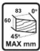
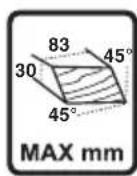
 | 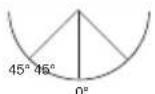 | Max A x Max B | |
| 0° 0° |  | 60 x 120 mm | |
| 45° 0° |  | 30 x 120 mm | |
| 0° 45° | 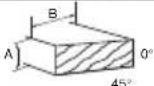 | 60 x 83 mm | |
| 45° 45° |  | 30 x 83 mm |
⑮a



natural_image
Technical line drawing of a mechanical cutting machine with wooden base and tool (no text or symbols)b

⑯ a


natural_image
Technical line drawing of a mechanical assembly with labeled components (no readable text or symbols)⑯ b

natural_image
Technical line drawing of a mechanical assembly with no visible text or symbols



24 a
natural_image
Technical line drawing of a mechanical assembly with no visible text or symbols⑳ b

* NOT STANDARD INCLUDED
24^c

25

natural_image
Technical line drawing of a mechanical assembly with a wooden base and clamping tool (no text or symbols)
27


GB
Mitre saw 1305
INTRODUCTION
- This tool is intended as a stationary machine for lengthways and crossways cutting of wood with straight cuts as well as angle cuts (horizontal mitre angles of -47^ to +47^ as well as vertical bevel angles of 0^ to 45^ are possible)
- Read and save this instruction manual ②
• This tool is not intended for professional use - Only use the tool when correctly and completely assembled (be aware that Skil cannot be hold responsible for tool damage and/or personal injuries resulting from the incorrect assembly of the tool)
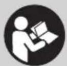
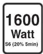
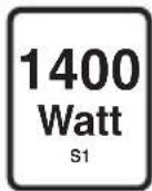
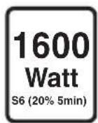
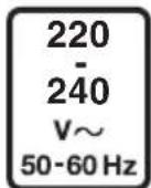
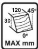
TECHNICAL DATA①
TOOL ELEMENTS ⑦
A Lower guard
B Switch handle
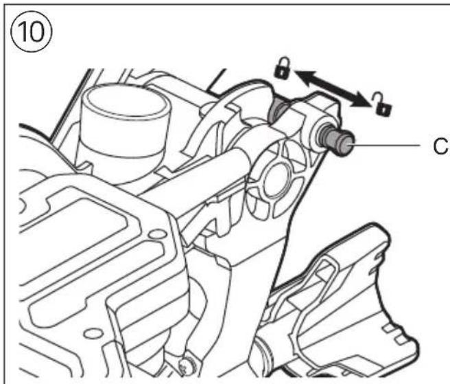
C Locking pin for transport
D Upper guard
E Transport handle
F Mounting holes
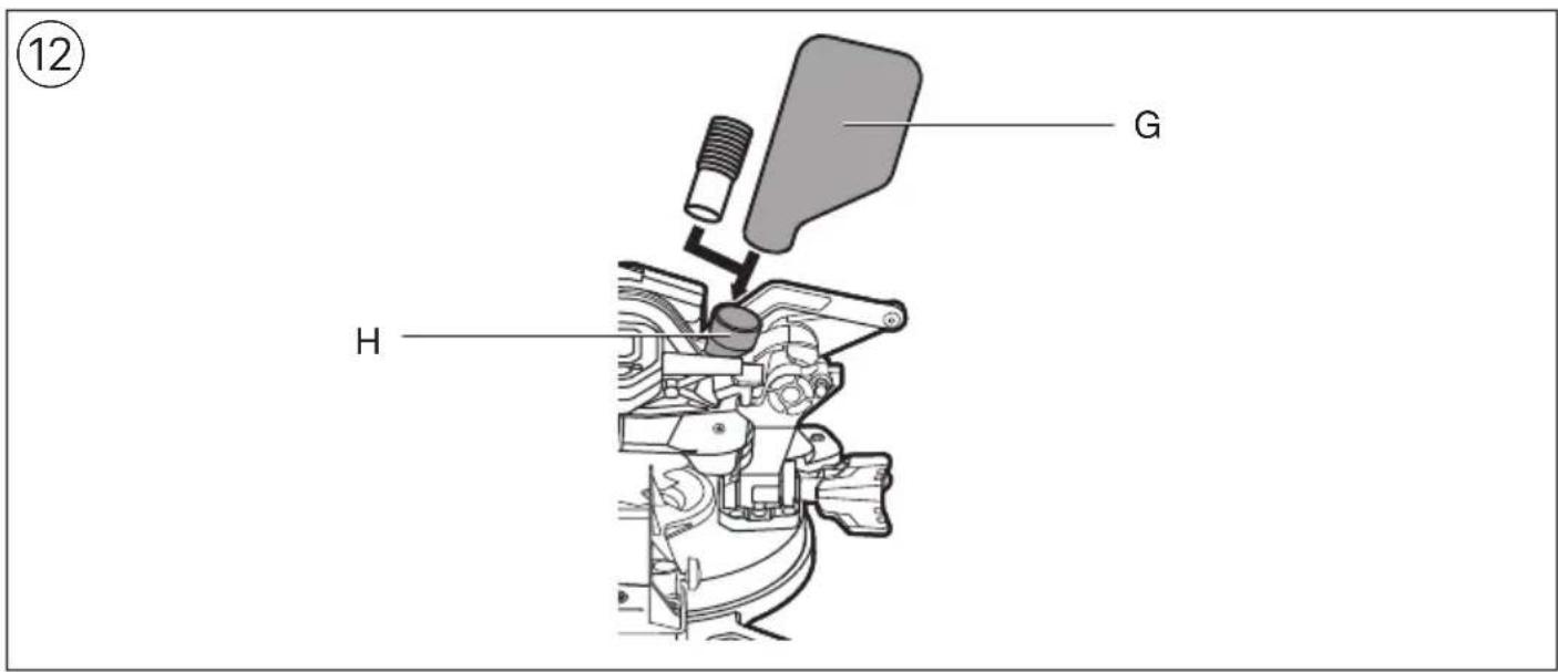
G Dust bag
H Dust port
J Sliding fence
K Knob for fastening sliding fence
L Clamp for mounting workpiece
M Support hole
N Knob for fastening clamp
P Knob for adjusting clamp
Q Clamping lever
R Fence
S Hex screws for adjusting fence (2x)
T Locking knob (bevel angles)
U Bevel angle indicator
V Screw for adjusting bevel angle (right)
W Screw for adjusting bevel angle (left)
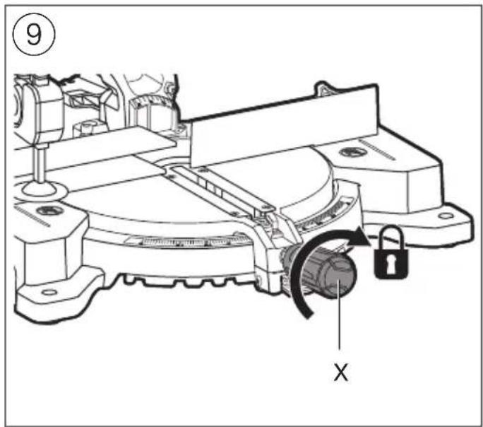
X Locking handle (mitre angles)
Y Mitre detent release lever
Z Mitre angle indicator
AA On/off switch
AB Safety lever
AC Hex key
AD Storage for hex key
AE Spindle-lock button
AF Cover plate screw
AG Blade bolt
AH Flange
AI Table insert
AJ Dust deflector
SAFETY
GENERAL POWER TOOL SAFETY WARNINGS
WARNING Read all safety warnings, instructions, illustrations and specifications provided with this power tool. Failure to follow all instructions listed below may result in electric shock, fire and/or serious injury.
Save all warnings and instructions for future reference.
The term "power tool" in the warnings refers to your mains-operated (corded) power tool or battery-operated (cordless) power tool.
1) WORK AREA SAFETY
a) Keep work area clean and well lit. Cluttered or dark areas invite accidents.
b) Do not operate power tools in explosive atmospheres, such as in the presence of flammable liquids, gases or dust. Power tools create sparks which may ignite the dust or fumes.
c) Keep children and bystanders away while operating a power tool. Distractions can cause you to lose control.
2) ELECTRICAL SAFETY
a) Power tool plugs must match the outlet. Never modify the plug in any way. Do not use any adapter plugs with earthed (grounded) power tools. Unmodified plugs and matching outlets will reduce risk of electric shock.
b) Avoid body contact with earthed or grounded surfaces such as pipes, radiators, ranges and refrigerators. There is an increased risk of electric shock if your body is earthed or grounded.
c) Do not expose power tools to rain or wet conditions. Water entering a power tool will increase the risk of electric shock.
d) Do not abuse the cord. Never use the cord for carrying, pulling or unplugging the power tool. Keep cord away from heat, oil, sharp edges or moving parts. Damaged or entangled cords increase the risk of electric shock.
e) When operating a power tool outdoors, use an extension cord suitable for outdoor use. Use of a cord suitable for outdoor use reduces the risk of electric shock.
f) If operating a power tool in a damp location is unavoidable, use a residual current device (RCD) protected supply. Use of an RCD reduces the risk of electric shock.
3) PERSONAL SAFETY
a) Stay alert, watch what you are doing and use common sense when operating a power tool. Do not use a power tool while you are tired or under the influence of drugs, alcohol or medication. A moment of inattention while operating power tools may result in serious personal injury.
b) Use personal protective equipment. Always wear eye protection. Protective equipment such as a dust mask, non-skid safety shoes, hard hat, or hearing protection used for appropriate conditions will reduce personal injuries.
c) Prevent unintentional starting. Ensure the switch is in the off-position before connecting to power source and/or battery pack, picking up or carrying the tool. Carrying power tools with your finger on the switch or energising power tools that have the switch on invites accidents.
d) Remove any adjusting key or wrench before turning the power tool on. A wrench or a key left attached to a rotating part of the power tool may result in personal injury.
e) Do not overreach. Keep proper footing and balance
at all times. This enables better control of the power tool in unexpected situations.
f) Dress properly. Do not wear loose clothing or jewellery. Keep your hair and clothing away from moving parts. Loose clothes, jewellery or long hair can be caught in moving parts.
g) If devices are provided for the connection of dust extraction and collection facilities, ensure these are connected and properly used. Use of dust collection can reduce dust-related hazards.
h) Do not let familiarity gained from frequent use of tools allow you to become complacent and ignore tool safety principles. A careless action can cause severe injury within a fraction of a second.
4) POWER TOOL USE AND CARE
a) Do not force the power tool. Use the correct power tool for your application. The correct power tool will do the job better and safer at the rate for which it was designed.
b) Do not use the power tool if the switch does not turn it on and off. Any power tool that cannot be controlled with the switch is dangerous and must be repaired.
c) Disconnect the plug from the power source and/or remove the battery pack, if detachable, from the power tool before making any adjustments, changing accessories, or storing power tools. Such preventive safety measures reduce the risk of starting the power tool accidentally.
d) Store idle power tools out of the reach of children and do not allow persons unfamiliar with the power tool or these instructions to operate the power tool. Power tools are dangerous in the hands of untrained users.
e) Maintain power tools and accessories. Check for misalignment or binding of moving parts, breakage of parts and any other condition that may affect the power tool's operation. If damaged, have the power tool repaired before use. Many accidents are caused by poorly maintained power tools.
f) Keep cutting tools sharp and clean. Properly maintained cutting tools with sharp cutting edges are less likely to bind and are easier to control.
g) Use the power tool, accessories and tool bits etc., in accordance with these instructions, taking into account the working conditions and the work to be performed. Use of the power tool for operations different from those intended could result in a hazardous situation.
h) Keep handles and grasping surfaces dry, clean and free from oil and grease. Slippery handles and grasping surfaces do not allow for safe handling and control of the tool in unexpected situations.
5) SERVICE
a) Have your power tool serviced by a qualified repair person using only identical replacement parts. This will ensure that the safety of the power tool is maintained.
SAFETY INSTRUCTIONS FOR MITRE SAWS
- Mitre saws are intended to cut wood or wood-like products, they cannot be used with abrasive cut-off wheels for cutting ferrous materials such as bars, rods, studs, etc Abrasive dust causes moving parts such as lower guard to jam. Sparks from abrasive cutting
will burn the lower guard, the kerf insert and other plastic parts.
- Use clamps to support workpiece whenever possible. If supporting the workpiece by hand, you must always keep hand at least 100 mm from either side of the saw blade. Do not use this saw to cut pieces that are too small to be securely clamped or held by hand. If your hand is placed too close to the saw blade, there is an increased risk of injury from blade contact.
- The workpiece must be stationary and clamped or held against both the fence and the table. Do not feed the workpiece into the blade or cut “freehand” in any way Unrestrained or moving workpieces could be thrown at high speeds, causing injury.
- Push the saw through the workpiece. Do not pull the saw through the workpiece. To make a cut, raise the saw head and pull it out over the workpiece without cutting, start the motor, press the saw head down and push the saw through the workpiece. Cutting on the pull stroke is likely to cause the saw blade to climb on top of the workpiece and violently throw the blade assembly towards the operator.
- Never cross your hand over the intended line of cutting either in front or behind the saw blade Supporting the workpiece “cross handed” i.e. holding the workpiece to the right of the saw blade with your left hand or vice versa is very dangerous.
- Do not reach behind the fence with either hand closer than 100 mm from either side of the saw blade, to remove wood scraps, or for any other reason while the blade is spinning The proximity of the spinning saw blade to your hand may not be obvious and you may be seriously injured.
- Inspect your workpiece before cutting If the workpiece is bowed or warped, clamp it with the outside bowed face toward the fence. Always make certain that there is no gap between the workpiece, fence and table along the line of the cut Bent or warped workpieces can twist or shift and may cause binding on the spinning saw blade while cutting. There should be no nails or foreign objects in the workpiece.
- Do not use the saw until the table is clear of all tools, wood scraps, etc, except for the workpiece Small debris or loose pieces of wood or other objects that contact the revolving blade can be thrown with high speed.
- Cut only one workpiece at a time Stacked multiple workpieces cannot be adequately clamped or braced and may bind on the blade or shift during cutting.
- Ensure the mitre saw is mounted or placed on a level, firm work surface before use. A level and firm work surface reduces the risk of the mitre saw becoming unstable.
- Plan your work! Every time you change the bevel or mitre angle setting, make sure the adjustable fence is set correctly to support the workpiece and will not interfere with blade or the guarding system. Without turning the tool "ON" and with no workpiece on the table, move the saw blade through a complete simulated cut to assure there will be no interference or danger of cutting the fence.
- Provide adequate support such as table extensions, saw horses, etc. for a workpiece that is wider or longer than the table top. Workpieces longer or wider than the mitre saw table can tip if not securely supported.
If the cut-off piece or workpiece tips, it can lift the lower guard or be thrown by the spinning blade.
- Do not use another person as a substitute for a table extension or as additional support Unstable support for the workpiece can cause the blade to bind or the workpiece to shift during the cutting operation pulling you and the helper into the spinning blade.
- The cut-off piece must not be jammed or pressed by any means against the spinning saw blade if confined, i.e. using length stops, the cut-off piece could get wedged against the blade and thrown violently.
- Always use a clamp or a fixture designed to properly support round material such as rods or tubing. Rods have a tendency to roll while being cut, causing the blade to "bite" and pull the work with your hand into the blade.
- Let the blade reach full speed before contacting the workpiece This will reduce the risk of the workpiece being thrown.
- If the workpiece or blade becomes jammed, turn the mitre saw off. Wait for all moving parts to stop and disconnect the plug from the power source and/or remove the battery pack. Then work to free the jammed material Continued sawing with a jammed workpiece could cause loss of control or damage to the mitre saw.
- After finishing the cut, release the switch, hold the saw head down and wait for the blade to stop before removing the cut-off piece Reaching with your hand near the coasting blade is dangerous.
- Hold the handle firmly when making an incomplete cut or when releasing the switch before the saw head is completely in the down position The braking action of the saw may cause the saw head to be suddenly pulled downward, causing a risk of injury.
ADDITIONAL SAFETY INSTRUCTIONS
- Inrush currents cause short-time voltage drops; under unfavourable power supply conditions, other equipment may be affected (if the system impedance of the power supply is lower than 0.33 Ohm, disturbances are unlikely to occur); if you need further clarification, you may contact your local power supply authority
GENERAL
- Only use the tool for cutting wood
- Always check that the supply voltage is the same as the voltage indicated on the nameplate of the tool
- Do not stand on tool or its stand Serious injury may occur if the tool is tipped or if the cutting tool is accidentally contacted. Do not store materials on or near the tool such that it is necessary to stand on the tool or its stand to reach them.
• Always disconnect plug from power source before making any adjustment or changing any accessory
- Always disconnect plug from power source before transporting the mitre saw Unplug, lower head assembly and lock into position, use the carry handle and one of the hand indentations in the saw base.
- Do not leave tool until it comes to a complete stop
- When cutting irregularly shaped workpieces, plan your work so it will not slip and pinch the blade and be torn from your hand
- This tool should not be used by people under the age of 16 years
• This tool is not suitable for wet cutting
OUTDOOR USE
- When used outdoors, connect the tool via a fault current (FI) circuit breaker with a triggering current of 30 mA maximum, and only use an extension cord which is intended for outdoor use and equipped with a splashproof coupling-socket
BEFORE USE
- Use completely unrolled and safe extension cords with a capacity of 16 Amps (U.K. 13 Amps)
- Wear protective glasses, hearing protection, and protective gloves
- Dust from material such as paint containing lead, some wood species, minerals and metal may be harmful (contact with or inhalation of the dust may cause allergic reactions and/or respiratory diseases to the operator or bystanders); wear a dust mask and work with a dust extraction device when connectable
- Certain kinds of dust are classified as carcinogenic (such as oak and beech dust) especially in conjunction with additives for wood conditioning; wear a dust mask and work with a dust extraction device when connectable
- Follow the dust-related national requirements for the materials you want to work with
- Do not work materials containing asbestos (asbestos is considered carcinogenic)
- Never use the tool without the original protection guard system
- Check the protective guard for proper closing before each use
- Do not operate the saw if the protective guard does not move freely and close instantly
- Never clamp or tie the protective guard into the open position
- Never use the tool without the table insert; replace a defective or worn table insert
- Remove all obstacles on top of as well as underneath the cutting path before you start cutting
- Avoid damage that can be caused by screws, nails and other elements in your workpiece; remove them before you start working
- Never use grinding/cutting discs with this tool
- SKIL can assure flawless functioning of the tool only when the correct accessories are used which can be obtained from your SKIL dealer
- For mounting/using non-SKIL accessories observe the instructions of the manufacturer concerned
- Use only saw blades that correspond with the characteristic data given in these operation instructions and that are tested and marked in accordance with EN 847-1
- Use only accessories with an allowable speed matching at least the highest no-load speed of the tool
- Never use saw blades made of high speed steel (HSS)
- Do not use a saw blade which is cracked, deformed or dull
- Only use saw blades with a hole diameter which fits the tool spindle without play; never use reducors or adaptors to fit large-hole saw blades
- Protect accessories from impact, shock and grease
ACCESSORIES
DURING USE
- Do not force the tool (apply light and continuous pressure in order to avoid overheating the blade tips and, in case of cutting plastics, melting the plastic material)
-
Keep fingers, hands and arms away from the rotating saw blade
-
If the saw blade becomes blocked, switch off the tool immediately and disconnect the plug; only then remove the wedged workpiece
- In case of jamming or electrical or mechanical malfunction, immediately switch off the tool and disconnect the plug
- If the cord is damaged or cut through while working, do not touch the cord, but immediately disconnect the plug
- Never use the tool when the cord is damaged; it must be replaced by a specially prepared cord available through the service organization.
AFTER USE
• After switching off the tool, never stop the rotation of the accessory by a lateral force applied against it
- Only remove cut-offs or other parts of the workpiece from the cutting area when all moving parts have come to a complete standstill
- the saw blade becomes very hot during use; do not touch it before it has cooled down
- Store the tool indoors in a dry and locked-up place, out of reach of children
EXPLANATION OF SYMBOLS ON TOOL
② Read the instruction manual before use
③ Wear protective glasses and hearing protection
④ Danger area! No hands zone. Keep hands, fingers or arms away from this area.
⑤ Double insulation (no earth wire required)
⑥ Do not dispose of electric tools and batteries together with household waste material
WHEN CONNECTING NEW 3-PIN PLUG (U.K. ONLY):
- Do not connect the blue (= neutral) or brown (= live) wire in the cord of this tool to the earth terminal of the plug
- If for any reason the old plug is cut off the cord of this tool, it must be disposed of safely and not left unattended
USE
- Assembly
- assemble three-legged knob at the back ^8
- assemble the mitre lock knob X into the front of the table ⑨
- Transport/working position
For releasing the tool (working position)
- press handle B downward with one hand while pulling out locking pin C with the other hand ⑩a
- guide the head assembly slowly upward
For securing the tool (transport position)
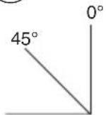
- set the bevel angle to 0^ (see Setting bevel angle)
- set the mitre angle to 45^ left or right (see Setting mitre angle)
- press handle B downward with one hand while pushing locking pin C with the other hand
- wind up the power cord
- use transport handle E for carrying the tool ⑩c
! never lift the tool by holding the main handle, or the power cord
- Mounting tool on working surface ⑪
! for safe handling always mount tool on a flat and stable working surface (e.g. workbench)
- use 4 mounting holes F for attaching the tool with suitable screws to the working surface
- you may also clamp the tool to the working surface with commercially available screw clamps
- alternatively, the tool can be mounted onto a mitre saw stand
! read all the warnings and instructions included with the saw stand
- Dust/chip extraction ⑫
- mount dustbag G/vacuum cleaner as illustrated
- empty dust bag regularly for optimal dust pick-up performance
! never let the vacuum cleaner hose interfere with the lower guard or the cutting operation
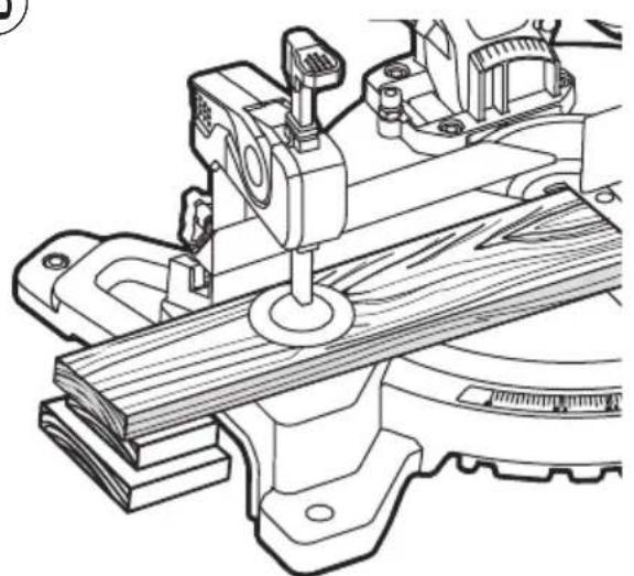
- Clamping the workpiece ⑬
! for optimum working safety always firmly clamp the workpiece with the adjustable clamp supplied
- do not work with workpieces that are too small to clamp
- for maximal workpiece dimensions use table ⑭ as reference
-
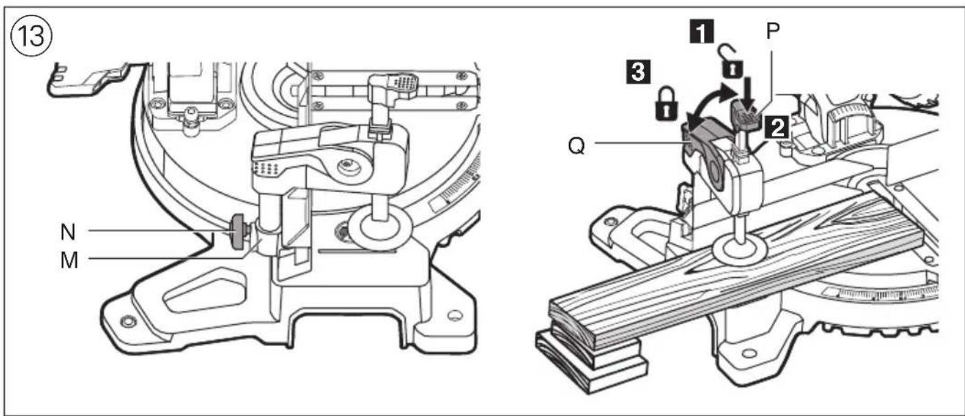
fasten workpiece clamp into support hole M with knob N (on either side of the tool)
-
press the workpiece firmly against fence R
- unlock lever Q
- adapt clamp to the workpiece
- firmly clamp the workpiece by locking lever Q
! for some mitre and bevel combinations, or depending on the size of the workpiece, it may be necessary to use commercially available screw clamps instead of the workpiece clamp
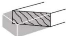
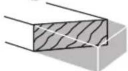
- Setting mitre angles ⑮
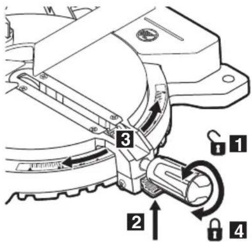
- loosen locking handle X
- pull mitre detent release lever Y
- rotate the saw table to the left or right and set the desired mitre angle (from 0° to 47°) by using indicator Z
- release lever Y
- tighten locking handle X (do not tighten the handle too firmly)
- for quick and precise setting of often used mitre angles (0°, 15°, 22.5°, 31.6°, 45°) the mitre detent lever clicks into place at the corresponding positions
- Adjusting the sliding fence
- loosen knob K to allow sliding of the fence(s) J
- loosen knob K further to allow removal / assembly of the fence(s)
- tighten knob K to secure the desired position
! make sure that the sliding fence is secured firmly before operating the tool
- Setting bevel angles ⑯
! slide sliding fence to the left
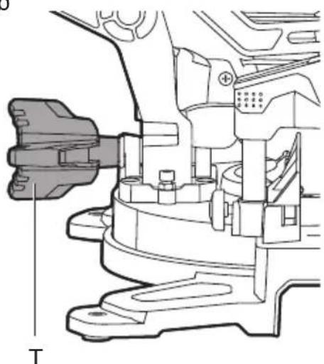
- loosen three-legged knob T ^16 b
- swing the saw head to the left until bevel angle indicator U points to the desired bevel angle
- hold the saw head in this position and tighten knob T
- Compound cuts ⑰
! remove sliding fence
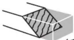
- compound cuts require both a mitre angle setting and a bevel angle setting
! always test out first on a piece of scrap material
- Operating the tool
- set tool into working position
! ensure that the workpiece is firmly clamped against the saw table and fence R
- switch on the tool by releasing the lock-off AB and pulling the main switch AA ⑲
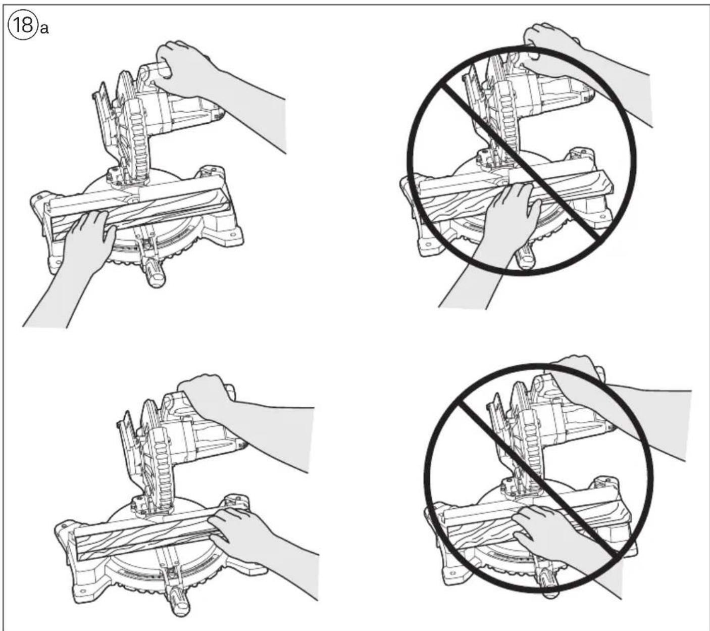
! do not cross your arms when operating the saw head ⑱a
! the tool should run at full speed before the blade enters into the workpiece
! if the lower guard does not automatically open which can happen under certain conditions (e.g. a workpiece which is very close to the maximum capacity) you may have to open the guard by hand ^18 b
- saw through the workpiece with uniform advancing
- switch off the tool by releasing switch AA
- wait until the sawblade has come to a complete standstill before guiding the saw head slowly upward
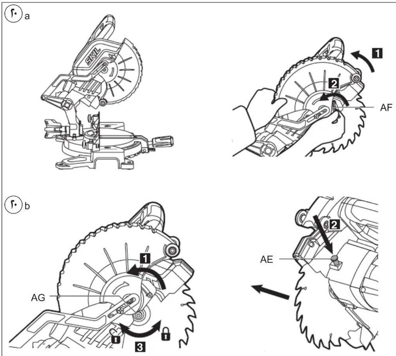
- Changing saw blade ⑳
! disconnect the plug
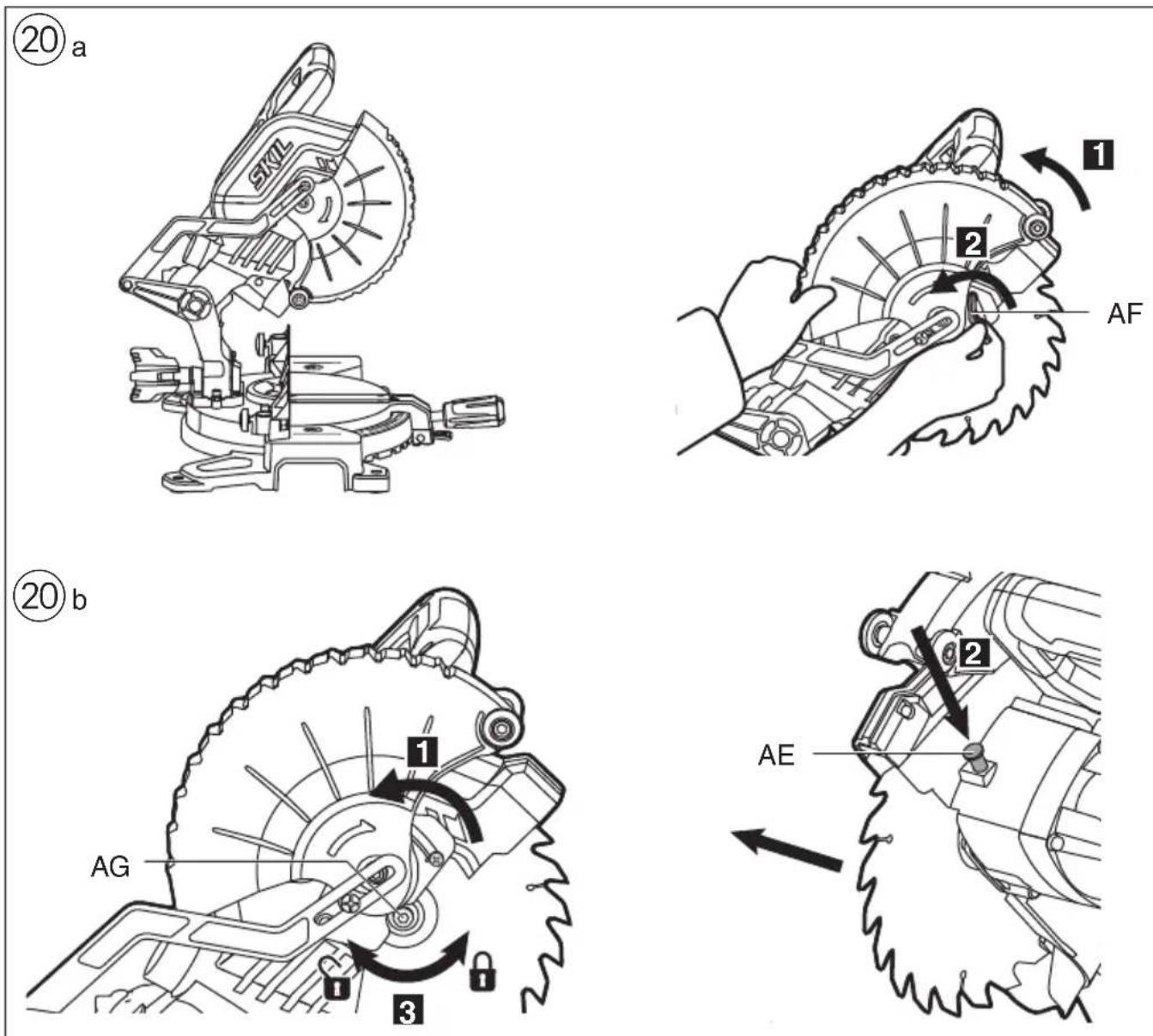
- take hex key AC from storage AD
- hold protective guard A in open position
- loosen cover plate screw AF (do not unscrew the screw completely) ⑳a
- rotate protective guard A completely backwards ⑳b
- push spindle-lock button AE and hold it while you remove blade bolt AG by turning hex key AC CLOCKWISE (= in same direction as arrow printed on saw blade)
! push spindle-lock button AE only when tool is at a standstill
- release spindle-lock button AE
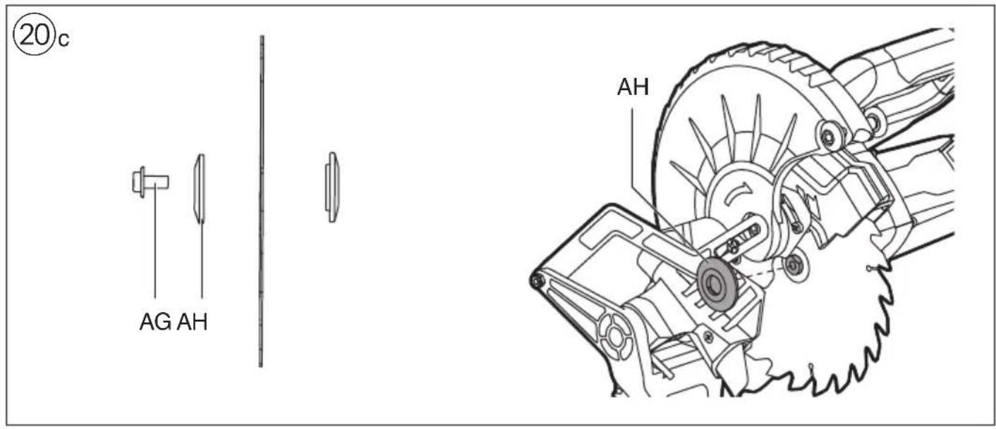
- remove flange AH and saw blade
! change saw blade with saw teeth and arrow printed on saw blade pointing in same direction as arrow on protective guard A
- mount flange AH _20 c
- push spindle-lock button AE and hold it while you tighten blade bolt by turning hex key AC COUNTER CLOCKWISE 1/8 turn past finger tight (ensures slippage of saw blade when it encounters excessive resistance thus reducing motor overload and saw kickback)
- tighten cover plate screw AF
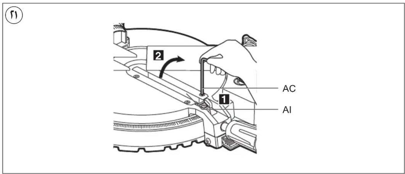
- Replacing table insert AI ⑳
Replace a defective or worn table insert as follows:
! disconnect the plug
- take hex key AC from storage AD
- remove all 4 screws as illustrated
- remove old table insert by first lifting it at the front and then pulling it out completely
- place new table insert
! firmly tighten all 4 screws
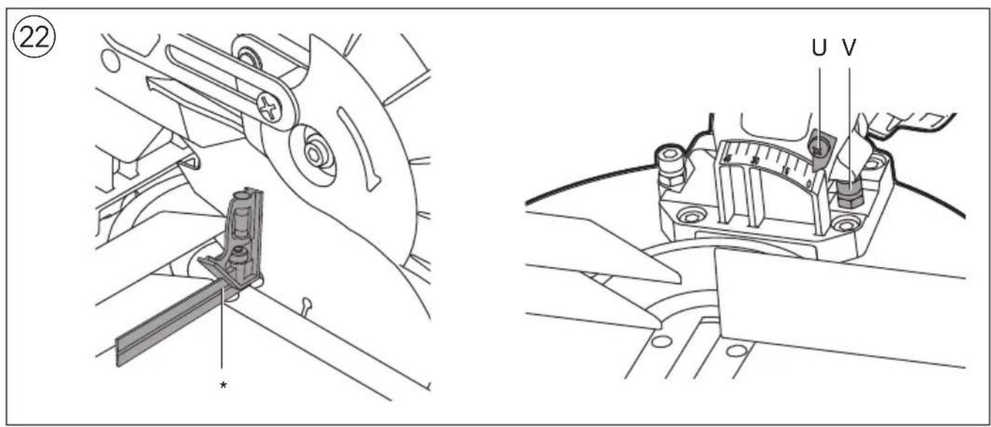
- Checking/adjusting of 90^ blade alignment ②2
! disconnect the plug
- rotate the saw table to the 0^ mitre position and lock in place
- swing the saw head to 0° bevel position
- lower the saw head and lock in place
- check for a 90° angle between blade and table with a square
-
if necessary, adjust the 90° blade alignment as follows:
-
loosen three-legged knob T
- adjust screw V with a blade wrench 10 (not standard included)
- re-check with square
- reset the bevel indicator U to 0°
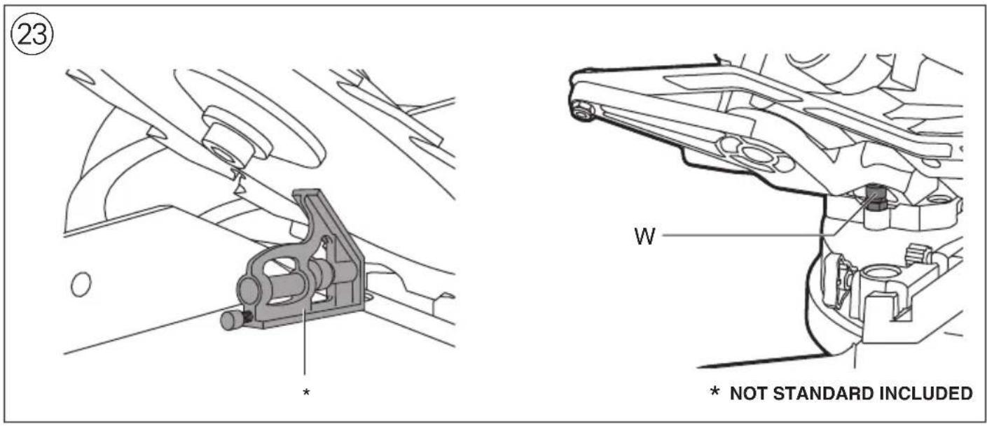
- Checking/adjusting of 45° blade alignment ②3
! disconnect the plug
- rotate the saw table to the 0^ mitre position and lock in place
- loosen three-legged knob T
-
swing the saw head to the left
-
check for a 45^ angle between blade and table with a mitre square
- check that bevel indicator U is on the 45° mark
-
if necessary, adjust the 45^ blade alignment as follows:
-
adjust screw W with a blade wrench 10 (not standard included)
- re-check with mitre square
- Checking/adjusting of 90^ fence alignment ②4! disconnect the plug
- rotate the saw table to the 0^ mitre position and lock in place
- lower the saw head and lock in place
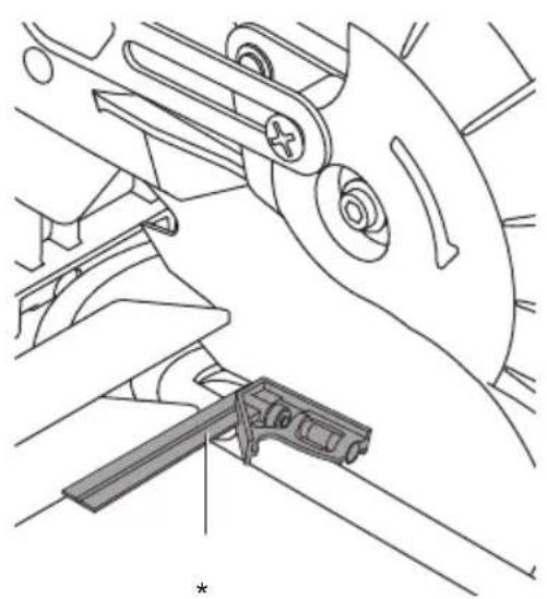
- check for a 90° angle between blade and fence S with a square (ensure the square contacts the saw blade body and not its teeth) ②a
-
if necessary, adjust the 90° fence alignment as follows:
-
loosen 2 hex screws S ⑳b
- adjust fence until blade and fence have full contact with the square
- tighten 2 hex screws S
- reset the mitre indicator to 0° 24c
APPLICATION ADVICE
- Special workpieces
- always support the free ends of a long workpiece ⑲
- ensure that curved or round workpieces are especially secured against slipping ^26
-
at the cutting line no gap may exist between the workpiece and the fence or saw table
-
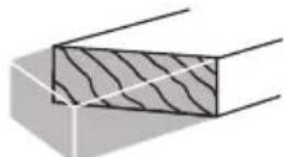
For working with floor mouldings illustration ⑳ can be used as reference
- Always face the good side of the workpiece down to ensure minimum splintering
-
Only use sharp saw blades of the correct type
-
quality of cut improves by the number of teeth
- carbide tipped blades stay sharp up to 30 times longer than ordinary blades
MAINTENANCE / SERVICE
- Always keep tool and cord clean (especially the ventilation slots at the back-end of the motor housing)
- Develop a regular check to make sure the lower guard is working properly. Clean the lower guard of any sawdust build up with a damp cloth.
! disconnect the plug before cleaning
- lift the lower guard to the fully open position and release it; if it does not immediately and fully close it should be checked by an after-sales service centre for SKIL power tools
- Clean saw blade immediately after use (especially from resin and glue)
! the saw blade becomes very hot during use; do not touch it before it has cooled down
- If the tool should fail despite the care taken in
manufacturing and testing procedures, repair should be carried out by an after-sales service centre for SKIL power tools
- send the tool undismantled together with proof of purchase to your dealer or the nearest SKIL service station (addresses as well as the service diagram of the tool are listed on www.skil.com)
- Be aware that damage due to overload or improper handling of the tool will be excluded from the warranty
(for the SKIL warranty conditions see www.skil.com or ask your dealer)
ENVIRONMENT
- Do not dispose of electric tools, batteries, accessories and packaging together with household waste material (only for EU countries)
- in observance of European Directive 2012/19/EC on waste of electric and electronic equipment and its implementation in accordance with national law, electric tools that have reached the end of their life must be collected separately and returned to an environmentally compatible recycling facility
- symbol ^6 will remind you of this when the need for disposing occurs
NOISE
- Measured in accordance with EN 62841 the sound pressure level of this tool is 99 dB(A) and the sound power level 108 dB(A) (uncertainty K = 3 dB)
- The noise emission level has been measured in accordance with a standardised test given in EN 62841; it may be used to compare one tool with another and as a preliminary assessment of exposure to noise when using the tool for the applications mentioned
- using the tool for different applications, or with different or poorly maintained accessories, may significantly increase the exposure level
- the times when the tool is switched off or when it is running but not actually doing the job, may significantly reduce the exposure level
F
Scie à onglets
1305
INTRODUCTION
WAARSCHUWING Lees alle
1) SIKKERHET PÅ ARBEIDSPLASSEN
a) Hold arbeidsområdet rent og ryddig. Rotete arbeidsområder eller arbeidsområder uten lys kan føre til ulykker.
VEDLIKEHOLD / SERVICE
AJ Vychyl'ovač prachu
BEZPEČNOST
VŠEOBECNÉ BEZPEČNOSTNÉ UPOZORNENIA TÝKAJÚCE SA ELEKTRICKÉHO NÁRADIA
ĎALŠIE BEZPEČNOSTNÉ POKYNY
DODATNA UPUTSTVA O SIGURNOSTI
NURGASAAGIDE OHUTUSJUHISED
APKALPOŠANA / APKOPE
TECHNINIAI DUOMENYS ①
PRIETAISO ELEMENTAI⑦
natural_image
Technical line drawing of a mechanical assembly with no visible text or symbolsfε b

natural_image
Technical line drawing of a mechanical assembly with an inset showing a close-up view of a component labeled 'Z' (no text or symbols beyond the label)50
natural_image
Technical line drawing of a mechanical assembly with wooden base and clamping tool (no text or symbols)




13
| | Max A x Max B | |
| 0° 0° | | 60 x 120 mm | |
| 45° 0° |  | 30 x 120 mm | |
| 0° 45° | 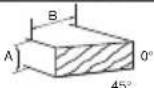 | 60 x 83 mm | |
| 45° 45° | 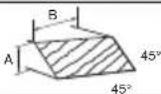 | 30 x 83 mm |
10a


natural_image
Technical line drawing of a mechanical cutting machine with wooden base and blade assembly (no text or symbols)b
⑪ a

natural_image
Technical line drawing of a mechanical assembly with no visible text or symbols17 b
natural_image
Technical line drawing of a mechanical assembly with no visible text or symbols


1 a c

natural_image
Technical line drawing of a mechanical assembly with no visible text or symbols
natural_image
Line drawing of a human silhouette holding a mechanical device, no text or symbols presentV

1
1305





1

natural_image
Icon of a person reading a book inside a black circle (no text or symbols)F

natural_image
Icon of a person wearing headphones and glasses, enclosed in a black circle (no text or symbols)③

natural_image
Black circular sign with a diagonal line crossing over two hands, symbolizing no hazard or caution (no text present)①

natural_image
Simple geometric diagram with two nested squares (no text or symbols)1

natural_image
Symbol of a trash bin crossed with no text or numbers, representing waste sorting or disposal (no text present)
natural_image
Technical illustration of a skil cutting machine with no visible text or symbols


- 1305
- GB
- Mitre saw 1305
- INTRODUCTION
- TECHNICAL DATA①
- TOOL ELEMENTS ⑦
- SAFETY
- GENERAL POWER TOOL SAFETY WARNINGS
- Save all warnings and instructions for future reference.
- 1) WORK AREA SAFETY
- 2) ELECTRICAL SAFETY
- 3) PERSONAL SAFETY
- SAFETY INSTRUCTIONS FOR MITRE SAWS
- ADDITIONAL SAFETY INSTRUCTIONS
- GENERAL
- OUTDOOR USE
- BEFORE USE
- ACCESSORIES
- DURING USE
- AFTER USE
- EXPLANATION OF SYMBOLS ON TOOL
- USE
- ! disconnect the plug
- APPLICATION ADVICE
- MAINTENANCE / SERVICE
- ! disconnect the plug before cleaning
- ! the saw blade becomes very hot during use; do not touch it before it has cooled down
- ENVIRONMENT
- NOISE
- F
- Scie à onglets
- WAARSCHUWING Lees alle
- VEDLIKEHOLD / SERVICE
- BEZPEČNOST
- VŠEOBECNÉ BEZPEČNOSTNÉ UPOZORNENIA TÝKAJÚCE SA ELEKTRICKÉHO NÁRADIA
- ĎALŠIE BEZPEČNOSTNÉ POKYNY
- DODATNA UPUTSTVA O SIGURNOSTI
- NURGASAAGIDE OHUTUSJUHISED
- APKALPOŠANA / APKOPE
- TECHNINIAI DUOMENYS ①
- PRIETAISO ELEMENTAI⑦
Brand : SKIL
Model : 1305 AA
Category : Saw