
POWDP75100 - Slicer PowerPlus - Free user manual and instructions
Find the device manual for free POWDP75100 PowerPlus in PDF.
| Product type | Tile cutter |
| Brand | PowerPlus |
| Model | POWDP75100 |
| Power supply | Lithium-ion battery 20 V DC (battery not included) |
| Blade diameter | 110 mm |
| Blade arbor | 22.2 mm |
| No-load speed | 3800 min⁻¹ |
| Cutting depth | 24 mm |
| Bevel cutting capacity | Yes, 45° guide |
| Miter cutting capacity | Yes, adjustable miter guide |
| Water cooling | Yes, integrated water tank |
| Blade material | Diamond tip |
| Cutting type | Straight, bevel, miter cut |
| Safety | Blade guard, on/off switch |
| Cleaning | Soft damp cloth, compressed air for slots |
| Maintenance | Regular check of moving parts |
| Repairability | Genuine spare parts, authorized service center |
| Warranty | 36 months |
| Charger | Charger included, for indoor use, LED indicator |
| Battery | Li-ion, compatible with supplied charger |
Frequently Asked Questions - POWDP75100 PowerPlus
User questions about POWDP75100 PowerPlus
0 question about this device. Answer the ones you know or ask your own.
Ask a new question about this device
Download the instructions for your Slicer in PDF format for free! Find your manual POWDP75100 - PowerPlus and take your electronic device back in hand. On this page are published all the documents necessary for the use of your device. POWDP75100 by PowerPlus.
USER MANUAL POWDP75100 PowerPlus
POWERPLUS HIGH QUALITY TOOLS
POWDP75100

natural_image
Close-up of a mechanical component with orange and black casing, showing internal structure and a tool inserted (no text or symbols visible)
natural_image
Close-up of a mechanical component with labeled part '12' (no other text or symbols visible)FIG. A
natural_image
Cross-sectional diagram of a mechanical or electrical component with internal structure and directional arrows (no text or symbols)Fig. 1a
natural_image
Technical line drawing of a mechanical assembly or assembly (no visible text or symbols)Fig.1c

natural_image
Close-up of a precision tool tip dispensing liquid into a metal mold (no text or symbols visible)Fig.1b
natural_image
Technical diagram of a mechanical assembly with gears and shafts (no visible text or labels)Fig. 1d
natural_image
Close-up of hands using a tool on a small wooden table (no visible text or symbols)Fig.1e
natural_image
Technical line drawing of a mechanical component with a threaded rod and rectangular base (no text or symbols)Fig.2a

natural_image
Diagram showing a metal bracket with a downward arrow pointing to a textured surface, no text or symbols present.Fig.2b
natural_image
Pure technical diagram of a mechanical bracket mounted on a conveyor belt (no text or symbols)Fig.2c
natural_image
Diagram showing a mechanical setup with a vertical component and downward force arrows, no text or symbols present.Fig.2d

natural_image
Technical line drawing of a mechanical assembly or assembly (no visible text or symbols)Fig.2e
natural_image
Close-up of a precision tool tip dispensing liquid into a black plastic tray (no text or symbols visible)Fig.2f
natural_image
Hand holding a black plastic tray with a small object on top, next to a grid-patterned tray (no text or symbols visible)Fig.2g
natural_image
Simple line drawing of a cylindrical object with a protruding rod and two small dots above it (no text or symbols)Fig.2h
natural_image
Close-up of a transparent plastic object resting on a dark striped surface (no text or symbols visible)Fig.2i
natural_image
Close-up of a black metal shelf with horizontal slats and a triangular top (no text or symbols visible)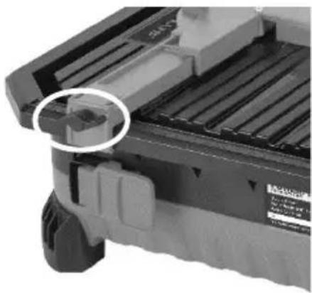
natural_image
Close-up of a mechanical component with a highlighted circular feature (no visible text or symbols)Fig.3a
natural_image
Diagram showing a bird silhouette above a building with a downward arrow, no text or symbols presentFig.3c
Fig.3b
natural_image
Technical diagram of a mechanical assembly with directional arrows indicating motion or force (no text or symbols present)Fig.3d
natural_image
Cross-sectional diagram of a mechanical or electrical component with internal structure and directional arrows (no text or symbols)Fig.4
natural_image
Technical line drawing of a mechanical assembly with no visible text or symbolsFig.5a
natural_image
Architectural cross-section diagram of a building facade with curved walls and horizontal beams (no text or symbols)Fig.5b

Fig.6
Green light

natural_image
Black and orange power bank battery with orange handle (no visible text or symbols)Fig.6a

natural_image
Close-up of a mechanical component with a white arrow pointing to a specific part (no visible text or symbols)Fig.7a

natural_image
Close-up of a mechanical component with a white arrow indicating a directional movement (no text or symbols visible)Fig.7b
natural_image
Technical line drawing of a mechanical device with no visible text or symbolsFig. 8a
natural_image
Illustration of a mechanical assembly with a black panel and vertical bars (no text or symbols)Fig. 8b

natural_image
Illustration of a person holding a book and a large object, with vertical bars and a bridge in the background (no text or symbols)Fig. 8c
POWDP75100
natural_image
Hand holding a black plastic tray with a small transparent object on top, no visible text or symbolsFig. 9a
natural_image
Close-up of a precision tool tip dispensing liquid into a black plastic mold (no text or symbols visible)Fig. 9b
natural_image
Technical line drawing of a mechanical assembly or assembly (no visible text or symbols)Fig. 9c
natural_image
Technical diagram of a mechanical assembly with gears and shafts (no visible text or labels)Fig. 9d

natural_image
Close-up of hands using a tool on a small wooden table (no visible text or symbols)Fig. 9e

natural_image
Close-up of a precision tool interacting with a black plastic tray (no visible text or symbols)Fig. 9f
natural_image
Hand holding a black plastic tray with a small transparent object inside, next to a metal grate (no text or symbols visible)Fig. 9g
1 TOEPASSING 3
2 BESCHRIJVING (FIG. A)....3
3 INHOUD VAN DE VERPAKKING....3
4 TOELICHTING VAN DE SYMBOLEN 3
5 ALGEMENE VEILIGHEIDSVOORSCHRIFTEN ....4
5.1 Werkplaats 4
5.2 Elektrische veiligheid 4
2 BESCHRIJVING (FIG. A)
09/11/2020, Lier - Belgium
1 UTILISATION .... 3
2 DESCRIPTION (FIG. A) 3
3 LISTE DES PIÈCES CONTENUES DANS L'EMBALLAGE .... 3
4 PICTOGRAMMES....3
5 CONSIGNES DE SÉCURITÉ GÉNÉRALES ......4
09/11/2020, Lier - Belgium
1 APPLICATION ....3
2 DESCRIPTION (FIG. A) 3
3 PACKAGE CONTENT LIST....3
4 SYMBOLS 3
5 GENERAL POWER TOOL SAFETY WARNINGS ....4
5.1 Working area....4
5.2 Electrical safety 4
5.3 Personal safety 4
5.4 Power tool use and care....5
5.5 Service....5
6 ADDITIONAL SAFETY INSTRUCTIONS FOR TILE CUTTERS....5
7 ADDITIONAL SAFETY INSTRUCTIONS FOR BATTERIES AND CHARGERS ......6
7.1 Batteries....6
7.2 Chargers....7
8 ASSEMBLY 7
8.1 Fitting the diamond blade 7
8.2 Fitting the blade guard 8
9 SET UP AND ADJUSTMENTS......8
9.1 Setting up the parallel fence 8
9.2 Setting up the mitre guide....8
9.3 Setting up the 45° fence....8
9.4 Water tank 8
10 OPERATION....9
10.1 Charging the battery pack....9
10.1.1 Charging indication (Fig 6)....9
10.2 Battery capacity indicator (Fig. 6a)....10
10.3 Inserting and removing the battery 10
10.4 On/off switch....10
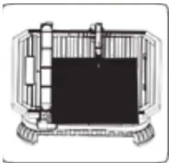
10.5 Straight cut (Fig. 8a)....10
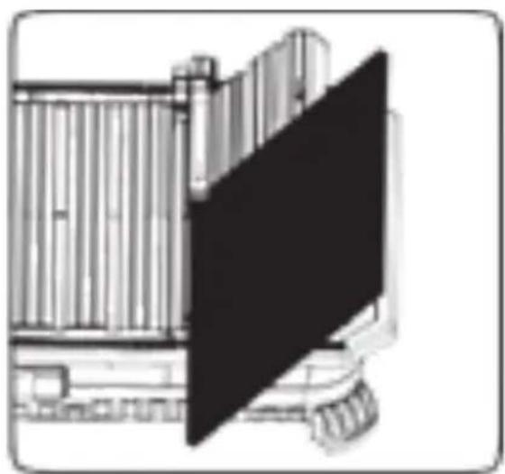
10.6 Bevel cut (Fig. 8b)....10
POWERPLUS HIGH QUALITY TOOLS
POWDP75100 EN
10.7 Mitre Cut (Fig. 8c)....10
11 CHANGING THE BLADE....11
11.1 How to switch blades .... 11
12 CLEANING AND MAINTENANCE 11
12.1 Cleaning....11
12.2 Maintenance....11
13 TECHNICAL DETAILS....12
14 NOISE....12
15 WARRANTY....12
16 ENVIRONMENT 13
17 DECLARATION OF CONFORMITY 13
TILE CUTTER 20 V (NO BATTERY)
POWDP75100
1 APPLICATION
- The power tool is intended for tile cutting. Not suitable for professional use.

WARNING! Read this manual and general safety instructions carefully before using the appliance, for your own safety. Your power tool should only be passed on together with these instructions.
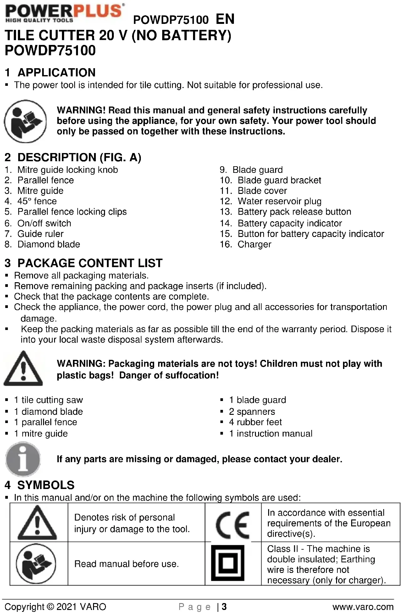
2 DESCRIPTION (FIG. A)
- Mitre guide locking knob
- Parallel fence
- Mitre guide
- 45^ fence
- Parallel fence locking clips
- On/off switch
- Guide ruler
-
Diamond blade
-
Blade guard
- Blade guard bracket
- Blade cover
- Water reservoir plug
- Battery pack release button
- Battery capacity indicator
- Button for battery capacity indicator
- Charger
3 PACKAGE CONTENT LIST
■ Remove all packaging materials.
- Remove remaining packing and package inserts (if included).
- Check that the package contents are complete.
- Check the appliance, the power cord, the power plug and all accessories for transportation damage.
- Keep the packing materials as far as possible till the end of the warranty period. Dispose it into your local waste disposal system afterwards.

WARNING: Packaging materials are not toys! Children must not play with plastic bags! Danger of suffocation!
■ 1 tile cutting saw
■ 1 diamond blade
■ 1 parallel fence
■ 1 mitre guide
■ 1 blade guard
■ 2 spanners
■ 4 rubber feet
■ 1 instruction manual

If any parts are missing or damaged, please contact your dealer.
4 SYMBOLS
- In this manual and/or on the machine the following symbols are used:
 | Denotes risk of personal injury or damage to the tool. |  | In accordance with essential requirements of the European directive(s). |
 | Read manual before use. |  | Class II - The machine is double insulated; Earthing wire is therefore not necessary (only for charger). |
 | Wear eye protection. |  | Wear noise protection. |
 | Wear gloves. | ||
 | Ambient temperature 40 °C max. (only for battery). |  | Do not expose charger and battery pack to water. |
 | Use battery and charger only in closed rooms. |  | Do not incinerate battery pack or charger. |
5 GENERAL POWER TOOL SAFETY WARNINGS
- Read all safety warnings and instructions. Failure to heed warnings and follow instructions may result in electric shock, fire and/or serious injury. Keep safety warnings and instructions for future reference. The term "power tool" in the safety warnings refers to your mains-operated (corded) power tool or battery-operated (cordless) power tool.
5.1 Working area
- Keep working area clean and well lit. Untidy and dark areas can lead to accidents. - Do not operate power tools in potentially explosive surroundings, for example, in the presence of inflammable liquids, gases or dust. Power tools create sparks which may ignite the dust or fumes.
- Keep children and bystanders at a distance when operating a power tool. Distractions can cause you to lose control of it.
5.2 Electrical safety
- Always check that the power supply corresponds to the voltage on the rating plate.
- Power tool plugs must match the outlet. Never modify the plug in any way. Do not use adapter plugs with earthed power tools. Unmodified plugs and matching outlets will reduce the risk of an electric shock.
- Avoid body contact with earthed surfaces such as pipes, radiators, kitchen ranges and refrigerators. There is an increased risk of an electric shock if your body is earthed.
- Do not expose power tools to rain or wet conditions. If water gets inside a power tool, it will increase the risk of an electric shock.
- Do not damage the cord. Never use the cord for carrying, pulling or unplugging the power tool. Keep the cord away from heat, oil, sharp edges or moving parts. Damaged or entangled cords increase the risk of an electric shock.
- When operating a power tool outdoors, use an extension cable suitable for outdoor use. Using a cord suitable for outdoor use reduces the risk of an electric shock.
- If operating a power tool in a damp location is unavoidable, use a power supply protected by a residual current device (RCD). Using an RCD reduces the risk of an electric shock.
5.3 Personal safety
- Stay alert, watch what you are doing and use common sense when operating a power tool. Do not use a power tool when you are tired or under the influence of drugs, alcohol or medication. A moment of inattention when operating a power tool may result in serious personal injury.
POWDP75100 EN
- Use safety equipment. Always wear eye protection. Using safety equipment such as a dust mask, non-skid safety shoes, a hard hat, or hearing protection whenever it is needed will reduce the risk of personal injury.
- Avoid accidental starts. Ensure the switch is in the off position before inserting the plug. Carrying power tools with your finger on the switch or plugging in power tools when the switch is in the on position makes accidents more likely.
- Remove any adjusting keys or spanners before turning on the power tool. A spanner or key left attached to a rotating part of the power tool may result in personal injury.
- Do not reach out too far. Keep your feet firmly on the ground at all times. This will enable you retain control over the power tool in unexpected situations.
- Dress properly. Do not wear loose clothing or jewellery. Keep your hair, clothing and gloves away from the power tool. Loose clothes, jewellery or long hair can become entangled in the moving parts.
- If there are devices for connecting dust extraction and collection facilities, please ensure that they are attached and used correctly. Using such devices can reduce dust-related hazards.
5.4 Power tool use and care
- Do not expect the power tool to do more than it can. Use the correct power tool for what you want to do. A power tool will achieve better results and be safer if used in the context for which it was designed.
- Do not use the power tool if the switch cannot turn it on and off. A power tool with a broken switch is dangerous and must be repaired.
- Disconnect the plug from the power source before making adjustments, changing accessories, or storing power tools. Such preventive safety measures reduce the risk of starting the power tool accidentally.
- Store power tools, when not in use, out of the reach of children and do not allow people who are not familiar with the power tool or these instructions to operate it. Power tools are potentially dangerous in the hands of untrained users.
- Maintain power tools. Check for misalignment or jammed moving parts, breakages or any other feature that might affect the operation of the power tool. If it is damaged, the power tool must be repaired. Many accidents are caused by using poorly maintained power tools.
- Keep cutting tools sharp and clean. Properly maintained cutting tools with sharp cutting edges are less likely to jam and are easier to control.
- Use the power tool, accessories and cutting tools, etc., in accordance with these instructions and in the manner intended for the particular type of power tool, taking into account the working conditions and the work which needs to be done. Using a power tool in ways for which it was not intended can lead to potentially hazardous situations.
5.5 Service
- Your power tool should be serviced by a qualified specialist using only standard spare parts. This will ensure that it meets the required safety standards.
6 ADDITIONAL SAFETY INSTRUCTIONS FOR TILE CUTTERS
- This appliance is not intended for use by persons (including children) with reduced physical, sensory or mental capabilities, or lack of experience and knowledge, unless they have been given supervision or instruction concerning use of the appliance by a person responsible for their safety.
- Only continuous rim diamond cutting-off wheel with ∅110 x ∅22.2mm can be used
- Young children should be supervised to ensure that they don't play with the appliance.
■ Make sure that the cutting blade is correctly screened by the guard.
- Never remove the safety guard bracket. The distance between the cutting blade and the safety guard bracket should not exceed 5mm.
POWDP75100 EN
- Do not use cutting blade which is bent, deformed or otherwise damaged.
- Do not use cutting blades which do not comply with the specifications stated in this manual.
- Never start cutting tiles before the machine reaches full speed.
- Never attempt to cut extremely small workpieces.
- Do not leave the work area until the machine has been switched off and the cutting disc has come to a complete standstill.
- Never attempt to stop the cutting blade by exerting pressure on the side of the blade.
- Always unplug the battery before performing any maintenance.
- Do not use the machine before it has been completely assembled and installed according the instructions.
- Do not perform any design, assembly or construction activities on the table while the machine is switched on.
- Unplug the battery and clean the table before leaving the work area.
Take care that the selection of the diamond discs is suitable for the material to be cut. - Faults in the machine, including guards or diamond discs, should be reported as soon as they are discovered. Never use the machine without the guard in position.
- Maximum size of working piece should be 1m^2 .
- This tile cutter should be used with limitations on ambient conditions (between 15 °C and 30 °C).
- Sharp edges and splinters of ceramic tiles can easily cause cuts. Wear work gloves for handling and while cutting tiles.
- Keep hands away from cutting area and blade.
- Keep your body positioned to either side of the blade, but not in line with the blade. Kickback could cause the tool to jump backwards.
- Do not reach underneath the workpiece. The guard cannot protect you from the blade below the workpiece.
- Do not attempt to remove cut material when the blade is rotating. Note that the blade will continue to coast for a while after the motor is switched off.
- Never wet cut with blades designed for dry cutting. There is danger of blade fracture and serious personal injury.
- Diamond blades do not cut material, rather they grind material to perform a cutting action. Do not feed the blade into the tile/masonry faster than the blade can grind.
- Never grind a tile using the side of the blade, or try to make radius or curve cuts. This will damage the blade and could cause blade fracture.
7 ADDITIONAL SAFETY INSTRUCTIONS FOR BATTERIES AND CHARGERS

Use only batteries and chargers applicable for this machine.
7.1 Batteries
- Never attempt to open for any reason.
- Do not store in locations where the temperature may exceed 40 °C.
- Charge only at ambient temperatures between 4 °C and 40 °C.
- Store your batteries in a cool dry place (5 °C-20 °C). Never store batteries in discharged state.
It is better for Li-ion batteries to discharge and reload them regularly (at least 4 times a year). The ideal charge for long-term storage of your Li-ion battery is 40% of capacity.
POWDP75100 EN
- When disposing of batteries, follow the instructions given in the section "Protecting the environment".
- Do not cause short circuits. If connection is made between the positive (+) and negative (-) terminal directly or via accidental contact with metallic objects, the battery is short circuited and an intense current will flow causing heat generation which may lead to casing rupture or fire.
- Do not heat. If batteries are heated to above 100 °C, sealing and insulating separators and other polymer components may be damaged resulting in electrolyte leakage and/or internal short circuiting leading to heat generation causing rupture or file. Moreover do not dispose of the batteries in fire, explosion and/or intense burning may result.
- Under extreme conditions, battery leakage may occur. When you notice liquid on the battery, proceed as follows:
- Carefully wipe the liquid off using a cloth. Avoid skin contact.
- In case of skin or eye contact, follow the instructions below:
- Carefully wipe the liquid off using a cloth. Avoid skin contact. - In case of skin or eye contact, follow the instructions below:
√ Immediately rinse with water. Neutralize with a mild acid such as lemon juice or vinegar.
√ In case of eye contact, rinse abundantly with clean water for at least 10 minutes. Consult a physician.

Fire hazard! Avoid short-circuiting the contacts of a detached battery. Do not incinerate the battery.
7.2 Chargers
■ Never attempt to charge non-rechargeable batteries.
■ Have defective cords replaced immediately.
■ Do not expose to water.
■ Do not open the charger.
- Do not probe the charger.
■ The charger is intended for indoor use only.
8 ASSEMBLY

Prior to using the tile cutting saw, the rubber feet, diamond blade, blade guard and parallel fence will need to be installed.
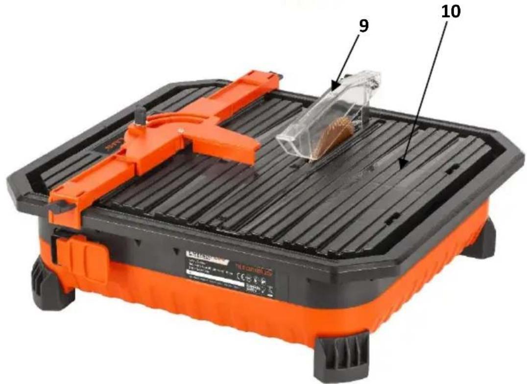
8.1 Fitting the diamond blade
- Remove the 45° fence. (Fig. 1a)
- Remove the screw and washer from the blade guard. (Fig. 1b)
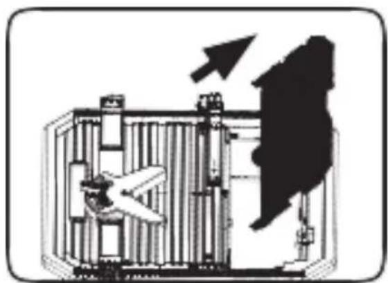
- Lift the blade cover out of its notch. (Fig. 1c)
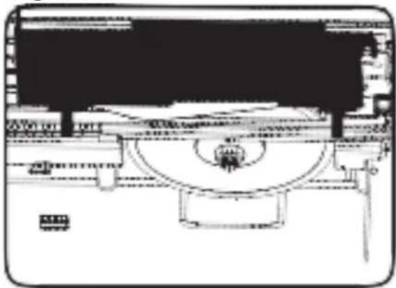
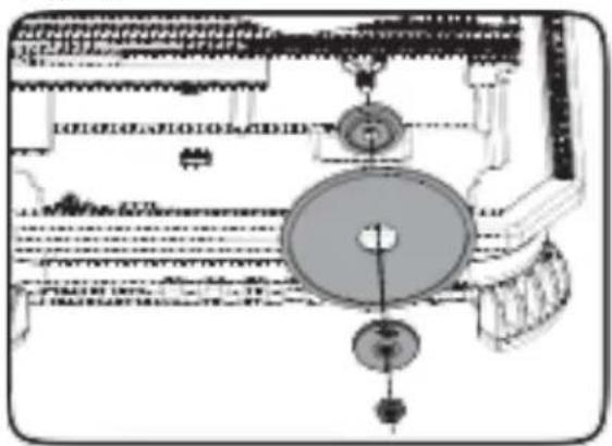
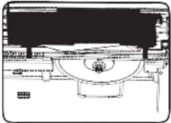
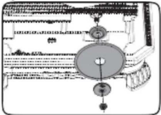
- Remove the blade nut and outer flange from the spindle. (Fig. 1d)
- Place the diamond blade on the spindle, so that it aligns centrally on the inner flange, then place the outer flange on the spindle.

Note: Ensure that the blade's rotation corresponds with the arrow marked on the housing.
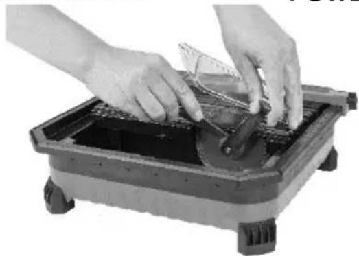
- Use the spanner which are included with this item to replace the blade nut. Stop the spindle from rotating with one spanner while tightening the blade nut with the other. (Fig. 1e)
POWDP75100 EN
8.2 Fitting the blade guard
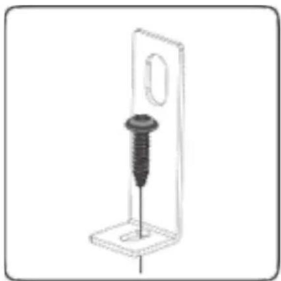
- Remove the screw and washer from the blade guard bracket. (Fig. 2a)
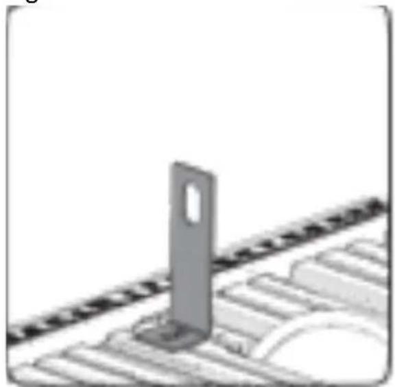
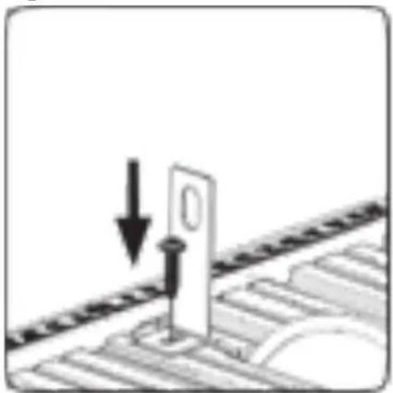
- Position the blade guard bracket within the reservoir. The 'L' part of the bracket should be pointed towards the centre of the table. (Fig. 2b)
- Slide the blade guard bracket up into the slot behind the diamond blade, at the rear of the table. (Fig. 2c)
- While holding the blade guard bracket upwards and in position, fasten it to the table top with the screw and washer. (Fig. 2d)

Note: Ensure the blade guard bracket is aligned to the center of the diamond blade.
- Slide the blade cover back into its original position. (Fig. 2e)
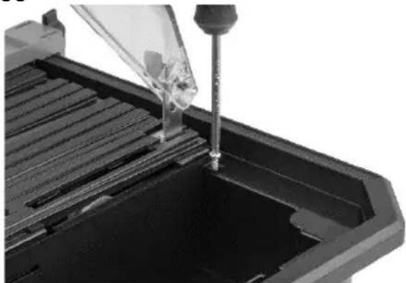
- Fasten the blade cover in place with the washer and screw. (Fig. 2f)
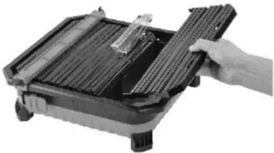
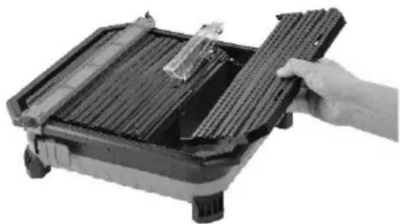
- Refit the 45° fence. (Fig. 2g)
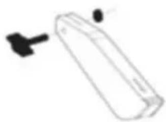
- Remove the knob, bolt and washer from the blade guard.
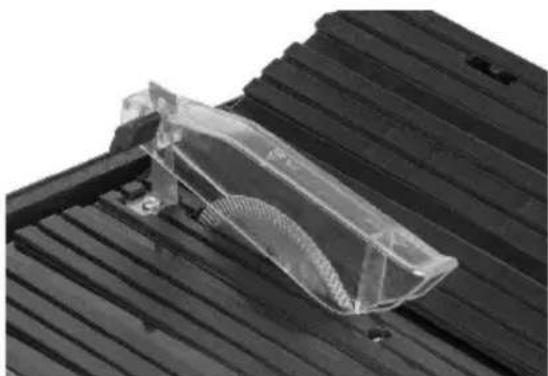
- Place the blade guard on to the blade guard bracket. Secure it in place with the bolt, washer and knob. Tighten the knob sufficiently to allow the blade guard to rest on the table but lift when the workpiece is pushed into the diamond blade. (Fig. 2h)
9 SET UP AND ADJUSTMENTS

WARNING! Ensure the battery is removed before performing any of the following operations.
9.1 Setting up the parallel fence
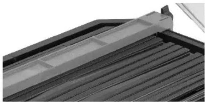
- Release the parallel fence locking clips and place the parallel fence on to the working table. Ensure that this is parallel to the blade. Use the guide ruler to assist in achieving the desired cutting width. (Fig. 3a)
- Secure the parallel fence in place with the parallel fence locking clips. (Fig. 3b)
9.2 Setting up the mitre guide
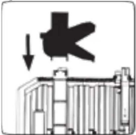
- After the parallel fence has been secured in place, the mitre guide can be clipped on to it. The mitre guide can be easily moved forwards and backwards on the parallel fence. (Fig. 3c)
- Loosen the mitre guide locking knob and adjust the mitre scale to the desired cutting angle, as displayed on the mitre gauge. Secure the mitre guide locking knob. (Fig. 3d)
9.3 Setting up the 45° fence
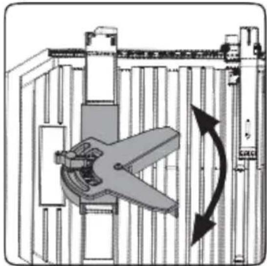
- Raise the 45° fence, lever out the support and locate the tabs into the corresponding holes in the deck. Ensure the fence is correctly secure before making a cut. (Fig. 4)
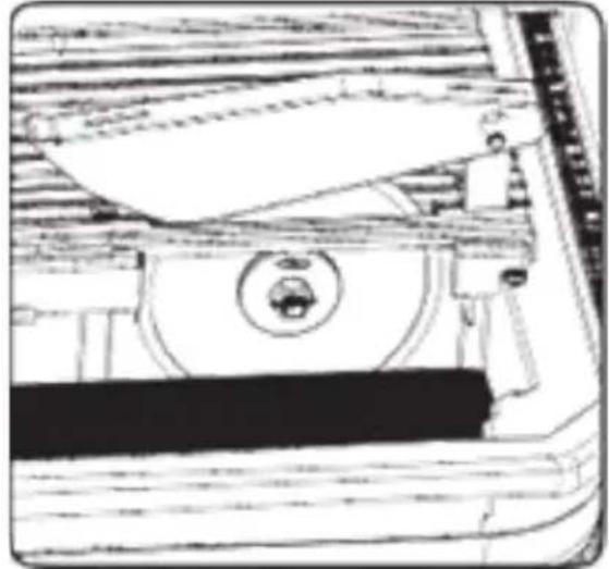
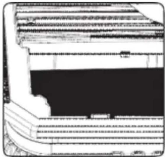
9.4 Water tank
- Remove the 45° fence and fill the water tank with clean water just enough to cover the diamond blade's bottom edge. No more than 14 of the diamond blade should be submerged in water. (Fig. 5a)
- When you have finished cutting, remove the plug inside the tank to drain the water. (Fig. 5b)

Note: The plug is also an over flow safety device, if the unit is over filled, water will spill out.

WARNING: Do not add chemicals or detergents to the water.
10 OPERATION
10.1 Charging the battery pack
- The battery pack for this tool is supplied in a low charge condition to prevent possible problems, therefore, you have to charge the battery before first use.

Note: Batteries will not reach full charge the first time they are charged. Allow several cycles for the item to fully charge. The battery should only be charged indoors.
- After normal use, about 1 hour of charging time is required for the battery to be fully charged.
- The battery pack will become slightly warm while charging, this is normal and does not indicate a problem.
- Do not place the charger in an area of extreme heat or cold. Best is at normal room temperature. When the battery becomes fully charged, unplug your charger from the power supply and remove the battery pack from the charger.
Note:
- Allow the battery pack to cool completely before charging.
- Inspect the battery pack before charging, do not charge a cracked or leaking battery pack.
10.1.1 Charging indication (Fig 6)
■ Connect the charger to the power outlet socket:
■ Solid green: ready to charge.
■ Flickering red: charging.
■ Solid green: charged.
- Solid green and red: battery or charger damaged.

Note: If the battery does not fit properly, disconnect it and confirm that the battery pack is the correct model for this charger as shown on the specification chart. Do not charge any other battery pack or any battery pack that does not securely fit the charger.
- Frequently monitor the charger and battery pack while connected.
- Unplug the charger and disconnect it from the battery pack when finished.
- Allow the battery pack to cool completely before using it.
- Store the charger and battery pack indoors, out of reach of children.

NOTE: If battery is hot after continuous use in the tool, allow it to cool down to room temperature before charging. This will extend the life of your batteries.

NOTE: Remove battery pack from charger stand which use your thumb or fingers, press the battery's release button in and pull the battery pack off at the same time.
10.2 Battery capacity indicator (Fig. 6a)
- There are battery capacity indicators on the battery pack, you can check the capacity status of the battery if you squeeze the button (12). Before using the machine, please press switch trigger to check if the battery is full enough for properly working.
- Those 3 LED might show the status of the capacity level of the battery:
■ 3 LED's are litt: Battery fully charged.
■ 2 LED's are litt: Battery 60% charged.
■ 1 LED is litt: Battery almost discharged.
10.3 Inserting and removing the battery

WARNING: Before making any adjustments ensure the tile cutter is switched off.
- Remove the battery: press the battery release latch in and at the same time pull the battery pack off.
- To insert the battery, push the battery pack onto the contacts of the tool.
10.4 On/off switch
■ Activate the tile cutting saw by pushing the on/off switch to the left (I). (Fig. 7a)
■ De-activate the tile cutting saw by pushing the on/off switch to the right end (0). (Fig. 7b)

CAUTION: Always allow the blade to reach full speed before performing any cutting operations.

WARNING!: The diamond blade will continue to rotate for a few seconds after the tile cutter has been switched off. Wait for the blade to stop before removing the blade.
10.5 Straight cut (Fig. 8a)
Adjust the parallel fence to the desired width. Securely hold the workpiece and evenly guide it with gentle pressure into the diamond blade. Hold the edges of the workpiece and press down firmly to prevent the workpiece from lifting during operation.
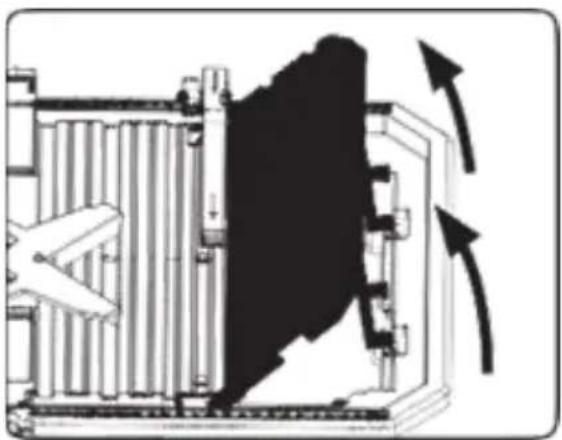
10.6 Bevel cut (Fig. 8b)
Raise the 45^ fence if you wish to cut an angle or bevel on the workpiece edge. Make the cut using the same technique as making a straight cut. Internal or external bevel cuts can be made by turning the workpiece face up or down.
With the mitre guide clipped on to the parallel fence, adjust the mitre angle to the desired angle. Securely hold the mitre guide and workpiece and evenly guide the workpiece into the diamond blade. Make sure that the workpiece fits firmly in the guide before making the cut.
11 CHANGING THE BLADE

CAUTION: Never use a blade that is too thick to allow the outer blade washer to engage with the flats on the spindle. It will prevent the blade screw from properly securing the blade onto the spindle.

CAUTION: Never try to use a blade that is larger than the stated capacity of the tile cutter. The blade might come into contact with the blade guard and risk personal injury or damage to the tile cutter. This will not be covered under the warranty.
11.1 How to switch blades
- Ensure the battery is disconnected from the machine.
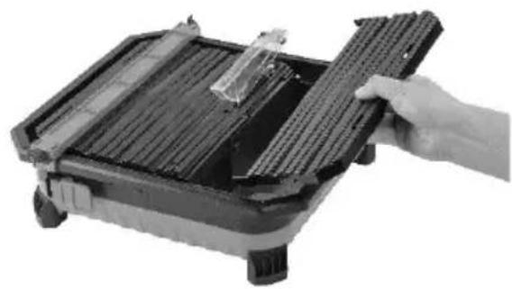
- Remove the 45° fence. (Fig. 9a)
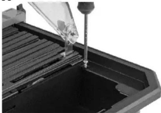
- Remove the screw and washer from the blade cover. (Fig. 9b)
- Lift the blade cover out of its notch. (Fig. 9c)
- Remove the blade nut, outer flange and old blade from the spindle. (Fig. 9d)
- Place the new diamond blade on the spindle, so that it is centrally aligned on the inner flange. Afterword's, place the outer flange on the spindle.

Note: Ensure that the blade's direction of rotation corresponds to the arrow marked on the housing.
- Replace the blade nut. The unit is supplied with 2 spanners, stop the spindle from rotating with one spanner while tightening the blade nut with the other. (Fig. 9e)
- Replace the blade cover back into its notch, then tighten the screw and washer.
- Refit the 45° fence. (Fig.9g)
12 CLEANING AND MAINTENANCE

IMPORTANT: Before cleaning your tile cutter or carrying out any maintenance procedures, make sure that the motor is de-activated and the battery is removed from the machine.
12.1 Cleaning
- Keep the ventilation slots of the tile cutting saw clean at all times and prevent any foreign matter from entering.
- If the housing of the tile cutting saw requires cleaning do not use solvents but a moist soft cloth only.
- Blow dust from the tile cutting saw through the ventilation slots with compressed air periodically to ensure a dust free tool.
12.2 Maintenance
- Our machines have been designed to operate over a long period of time with a minimum of maintenance. Continuous satisfactory operation depends upon proper machine care and regular cleaning.
13 TECHNICAL DETAILS
| Cutting wheel diameter: | 110 mm |
| Power supply | 20 Volt DC |
| Maximum speed | 3800 min-1 |
| Blade size | 110 mm x 22.2 mm |
| Cutting depth | 24 mm |
| Water tray | Yes |
| Blade material | Diamond tip |
14 NOISE
- Noise emission values measured according to relevant standard. (K=3)
Acoustic pressure level LpA 97 dB(A)
Acoustic power level LwA 106 dB(A)

ATTENTION! Wear hearing protection when sound pressure is over 85 dB(A).
15 WARRANTY
- This product is warranted for a 36-month period effective from the date of purchase by the first user.
- This warranty covers all material or production flaws excluding : batteries, chargers, defective parts subject to normal wear & tear such as bearings, brushes, cables, and plugs, or accessories such as drills, drill bits, saw blades, etc. ; damage or defects resulting from maltreatment, accidents or alterations; nor the cost of transportation.
- Damage and/or defects resulting from inappropriate use also do not fall under the warranty provisions.
- We also disclaim all liability for any bodily injury resulting from inappropriate use of the tool.
- Repairs may only be carried out by an authorised customer service centre for Powerplus tools.
- You can always obtain more information at the number 00 32 3 292 92 90.
- Any transportation costs shall always be borne by the customer, unless agreed otherwise in writing.
- At the same time, no claim can be made on the warranty if the damage of the device is the result of negligent maintenance or overload.
- Definitely excluded from the warranty is damage resulting from fluid permeation, excessive dust penetration, intentional damage (on purpose or by gross carelessness), inappropriate usage (use for purposes for which the device is not suitable), incompetent usage (e.g. not following the instructions given in the manual), inexpert assembly, lightning strike, erroneous net voltage. This list is not exhaustive.
- Acceptance of claims under warranty can never lead to the prolongation of the warranty period nor commencement of a new warranty period in case of a device replacement.
- Devices or parts which are replaced under the warranty therefore remain the property of Varo NV.
- We reserve the right to reject a claim whenever the purchase cannot be verified or when it is clear that the product has not been properly maintained. (Clean ventilation slots, carbon brushes serviced regularly, etc.).
- Your purchase receipt must be kept as proof of date of purchase.
- Your appliance must be returned undismantled to your dealer in an acceptably clean state, (in its original blow-moulded case if applicable to the unit), accompanied by proof of purchase.
- Your tool must be charged at least 1x per month to ensure optimal operation of this tool.
16 ENVIRONMENT

Should your appliance need replacement after extended use, do not dispose of it with the household refuse, but in an environmentally safe way.
Waste produced by electrical machine items should not be handled like normal household rubbish. Please recycle where recycle facilities exist. Check with your Local Authority or retailer for recycling advice.
17 DECLARATION OF CONFORMITY


VARO – Vic. Van Rompuy N.V. - Joseph Van Instraat 9 - BE2500 Lier - BELGIUM, declares that,
Product: Tile cutter – Battery operated
Trade mark: PowerPlus
Model: POWDP75100
is in conformity with the essential requirements and other relevant provisions of the applicable European Directives, based on the application of European harmonized standards. Any unauthorized modification of the apparatus voids this declaration.
European Directives (including, if applicable, their amendments up to the date of signature):
2011/65/EU
2006/42/EC
2014/30/EU
European harmonized standards (including, if applicable, their amendments up to the date of signature):
EN62841-1:2015
EN55014-1:2017
EN55014-2:2015
Keeper of the Technical Documentation : Philippe Vankerkhove, VARO – Vic. Van Rompuy N.V.
The undersigned acts on behalf of the company CEO,
Mertens Ludo
Regulatory Affairs – Compliance Manager 09/11/2020, Lier - Belgium
1 EINSATZBEREICH .... 3
09/11/2020, Lier - Belgium
1 APLICACIÓN ....3
10.4 Interruptor de encendido/apagado (on/off)....10
10.5 Corte recto (Fig. 8a)....11
POWERPLUS HIGH QUALITY TOOLS
POWDP75100 ES
10.6 Corte en bisel (Fig. 8b)....11
10.7 Corte en inglete (Fig. 8c)....11
11 CAMBIO DE LA HOJA ....11
11.1 Cambio de hojas....11
12 LIMPIEZA Y MANTENIMIENTO .... 12
12.1 Limpieza....12
12.2 Mantenimiento 12
13 CARACTERÍSTICAS TÉCNICAS....12
14 RUIDO 12
15 GARANTÍA....13
16 MEDIO AMBIENTE....13
17 DECLARACIÓN DE CONFORMIDAD....14
CORTADORA DE BALDOSAS 20 V (SIN BATERÍA) POWDP75100
1 APLICACIÓN
Regulatory Affairs – Compliance Manager
09/11/2020, Lier - Belgium
1 APLICAÇÃO....3
10.4 Interruptor On/Off (Ligar/Desligar)....11
09/11/2020, Lier - Belgium
1 BRUKSOMRÅDE....3
2 BESKRIVELSE (FIG. A) 3
3 PAKKENS INNHOLD 3
4 SYMBOLFORKLARING .... 3
5 GENERELLE SIKKERHETSADVARSLER 4
09/11/2020, Lier - Belgium
1 ANVENDELSE 3
2 BESKRIVELSE (FIG. A) 3
3 MEDF∅LGENDE INDHOLD 3
4 SYMBOLER....3
5 GENERELLE SIKKERHEDSFORSKRIFTER ....4
5.1 Arbejdsområde 4
5.2 Elektrisk sikkerhed....4
5.3 Personlig sikkerhed....4
Regulatory Affairs (afdelingen for juridiske anliggender) – Compliance Manager 09/11/2020, Lier - Belgium
1 ANVÄNDNINGSOMRÅDE 3
2 BESKRIVNING (FIG. A) 3
3 FÖRPACKNINGSINNEHÅLL 3
4 SYMBOLER....3
5 ALLMÄNNA SÄKERHETSANVISNINGAR FÖR ELEKTRISKA VERKTYG....4
3 FÖRPACKNINGSINNEHÅLL
09/11/2020, Lier - Belgium
09/11/2020, Lier - Belgium
1 ΕΦΑΡΜΟΓΗ....3
2 ПЕРИГРАФН (ЕИК. А)......3
09/11/2020, Lier - Belgium
1 PRIMJENA 3
2 OPIS (SLIKA A) 3
3 POPIS SADRŽAJA PAKETA 3
4 SIMBOLI....3
5 OPĆA UPOZORENJA O SIGURNOSTI RUKOVANJA ELEKTRIČNIM ALATIMA......4
09/11/2020, Lier - Belgium
1 OBLAST POUŽITÍ....3
2 POPIS (OBRÁZEK A) 3
3 OBSAH BALENÍ....3
4 SYMBOLY 4
5 OBECNÁ BEZPEČNOSTNÍ UPOZORNĚNÍ PRO ELEKTRICKÉ STROJE....4
09/11/2020, Lier - Belgium
1 POUŽÍVANIE....3
2 POPIS (OBR. A)....3
3 OBSAH BALENIA....3
4 SYMBOLY 3
5 VŠEOBECNÉ BEZPEČNOSTNÉ VAROVANIA PRE ELEKTRICKÉ NÁRADIE ....4
5.1 Pracovná plocha....4
09/11/2020, Lier - Belgium
1 DOMENII DE UTILIZARE....3
2 DESCRIERE (FIG. A)....3
3 CONTINUTUL PACHETULUI 3
4 SIMBOLURI....4
5 AVERTISMENTE GENERALE DE SIGURANTĂ PRIVIND APARATUL ELECTRIC....4
5.1 Zona de lucru....4
09/11/2020, Lier - Belgium
1 ZASTOSOWANIE ....3
2 OPIS (RYC. A)....3
3 SPIS CZEŚCI 3
4 SYMBOLE 3
5 OGÓLNE ZASADY BEZPIECZNEJ PRACY ELEKTRONARZĘDZIAMI......4
7.1 Akumulatory....7
7.2 Ładowarki....8
8 MONTAZ....8
09/11/2020, Lier - Belgium
09/11/2020, Lier - Belgium
1 ПРЕДНАЗНАЧЕНИЕ НА ЕЛЕКТРОИНСТРУМЕНТА....3
2 ОПИСАНИЕ (ФИГ. А) 3
3 СПИСЪК НА СЪДЪРЖАНИЕТО НА ОПАКОВКАТА....3
4 СИМВОЛИ .... 3
5 ОБЩИ ПРЕДУПРЕЖДЕНИЯ ЗА БЕЗОПАСНОСТ ПРИ ИЗПОЛЗВАНЕ НА ЕЛЕКТРОИНСТРУМЕНТИ......4
5.1 Работна зона ....4
natural_image
Orange and black industrial machine with slatted metal tray (no visible text or symbols)DISCOVER THE ENTIRE PRODUCT RANGE AT
WWW.DUAL-POWER.COM
- POWDP75100
- BESCHRIJVING (FIG. A)
- POWERPLUS HIGH QUALITY TOOLS
- POWDP75100 EN
- TILE CUTTER 20 V (NO BATTERY)
- APPLICATION
- DESCRIPTION (FIG. A)
- PACKAGE CONTENT LIST
- SYMBOLS
- GENERAL POWER TOOL SAFETY WARNINGS
- Working area
- Electrical safety
- Personal safety
- Power tool use and care
- Service
- ADDITIONAL SAFETY INSTRUCTIONS FOR TILE CUTTERS
- ADDITIONAL SAFETY INSTRUCTIONS FOR BATTERIES AND CHARGERS
- Batteries
- Fire hazard! Avoid short-circuiting the contacts of a detached battery. Do not incinerate the battery.
- Chargers
- ASSEMBLY
- Prior to using the tile cutting saw, the rubber feet, diamond blade, blade guard and parallel fence will need to be installed.
- Fitting the diamond blade
- Note: Ensure that the blade's rotation corresponds with the arrow marked on the housing.
- Fitting the blade guard
- Note: Ensure the blade guard bracket is aligned to the center of the diamond blade.
- SET UP AND ADJUSTMENTS
- WARNING! Ensure the battery is removed before performing any of the following operations.
- Setting up the parallel fence
- Setting up the mitre guide
- Setting up the 45° fence
- Water tank
- OPERATION
- Charging the battery pack
- Charging indication (Fig 6)
- Battery capacity indicator (Fig. 6a)
- Inserting and removing the battery
- On/off switch
- Straight cut (Fig. 8a)
- Bevel cut (Fig. 8b)
- CHANGING THE BLADE
- How to switch blades
- CLEANING AND MAINTENANCE
- Cleaning
- Maintenance
- TECHNICAL DETAILS
- NOISE
- ATTENTION! Wear hearing protection when sound pressure is over 85 dB(A).
- WARRANTY
- ENVIRONMENT
- DECLARATION OF CONFORMITY
- POWDP75100 ES
- CORTADORA DE BALDOSAS 20 V (SIN BATERÍA) POWDP75100
- APLICACIÓN
- FÖRPACKNINGSINNEHÅLL
Brand : PowerPlus
Model : POWDP75100
Category : Slicer