Aquaforce 15000 - Pump HOZELOCK - Free user manual and instructions
Find the device manual for free Aquaforce 15000 HOZELOCK in PDF.

| Type | Submersible and amphibious pump |
| Brand | Hozelock Cyprio |
| Model | Aquaforce 15000 |
| Power supply | 230 V ~ 50 Hz |
| Power consumption | 180 W |
| Maximum flow rate | 15,000 l/h |
| Maximum delivery head | 5.7 m |
| Protection rating | IPX8 |
| Maximum immersion depth | 2.5 m |
| Maximum water temperature | 35 °C |
| Amphibious use | Yes |
| Thermal overload protection | Yes, automatic shut-off |
| Small fish protection insert | Yes, reduces holes to 2 mm |
| Maximum particle diameter | 10 mm |
| Hose connection | 25 / 32 / 40 mm and 3/4" BSP |
| Power cable length | 10 m |
| Maintenance | Regular cleaning of the cage, annual disassembly of the rotor |
| Safety | Use with residual current device (RCD) 10-30 mA, mandatory earthing |
| Spare parts available | Rotor, seals, filter cage, adapters |
| Warranty | 3 years + 2 years after online registration |
| Winter storage | Store in a bucket of frost-free water |
Frequently Asked Questions - Aquaforce 15000 HOZELOCK
User questions about Aquaforce 15000 HOZELOCK
0 question about this device. Answer the ones you know or ask your own.
Ask a new question about this device
Download the instructions for your Pump in PDF format for free! Find your manual Aquaforce 15000 - HOZELOCK and take your electronic device back in hand. On this page are published all the documents necessary for the use of your device. Aquaforce 15000 by HOZELOCK.
USER MANUAL Aquaforce 15000 HOZELOCK
Midpoint Park, Birmingham,
B76 1AB. England
Tel: +44 (0) 121 313 1122
consumer.service@hozelock.com
www.hozelock.com
43389-003


Thank you for choosing a Hozelock quality product. You can be assured of many years of reliable service from this product.

THIS APPLIANCE IS FOR HOUSEHOLD USE. READ THESE INSTRUCTIONS CAREFULLY BEFORE ATTEMPTING INSTALLATION.
FAILURE TO OBSERVE THE FOLLOWING NOTICES MAY RESULT IN INJURY, PRODUCT DAMAGE OR LOSS OF FISH.
KEEP THESE INSTRUCTIONS FOR FUTURE REFERENCE.
YOU CAN ALSO DOWNLOAD THESE
INSTRUCTIONS AT http://www.hozelock.com/
customer-service/instruction-leaflets.html.
Contents
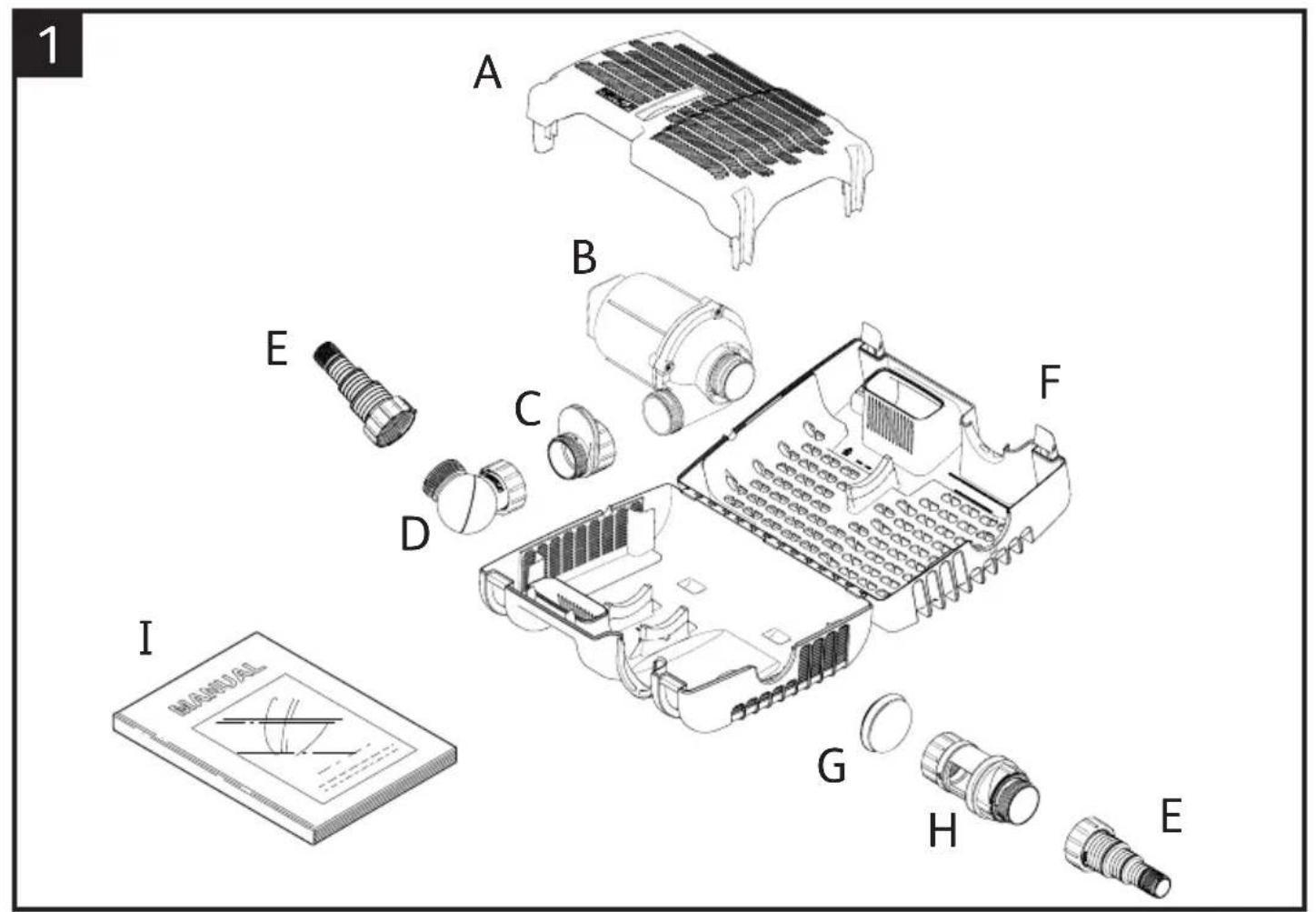
(Fig.1) Check all contents are present before installation.
A. Small Fish Protection Insert
B. Pump
C. Outlet adaptor
D. Ball Joint
E. Hosetail & Nut
F. Strainer Cage
G.End Cap
H. Flow Control
I. Instruction Manual
Introduction
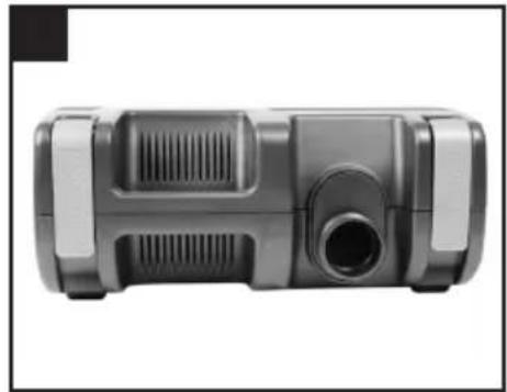
This Hozelock Cyprio Aquaforce pump is electrically operated and is designed to pump solid particles up to 10mm in diameter with minimal prestrainer maintenance. These types of pumps are particularly suitable for pumping water to external filters or for use in high flow waterfalls or watercourse applications where low maintenance is important. The pump does not use oil or grease for lubrication and can be used safely in ponds containing fish or plants. The motor consists of a sealed stator and water-cooled rotor. All electrical components are isolated from the water.
ATTENTION
AUTOMATIC CUT-OUT
To help ensure your pump's long life and to prevent damage, it is fitted with automatic thermal overload protection. This switches off the pump if it overheats. If this occurs, switch off the power at the mains supply to the pump. Check for the cause. Usually it will be debris blocking the inlets of the pump or obstructing the impeller. Remove the obstruction and wait for the pump to cool down. Then switch on the pump again.
General Safety Guidelines
- This pump has been designed for the use with ponds only. Only use this pump for the operation of pond filter systems, water displays, waterfalls etc. Do not use this pump for any other use (i.e. do not use this pump in swimming pools, bathrooms, central heating systems etc). Using the product for any other application may result in injury or product damage.
- Important - This appliance must only be used by a responsible adult who is capable of using the appliance in a safe way and who understands the hazards involved. Use and store this appliance out of reach of children and persons with reduced physical, sensory, or mental capabilities.
- WARNING: Always unplug or disconnect all appliances in the pond from the electricity supply before putting your hands in the water whilst equipment is being installed, repaired, maintained or handled. Never immerse the plugged end of the cable in water.
- Never use the mains supply cable to lift the pump, as this may cause damage. We recommend fitting a lifting cord to the handle on the strainer cage when the pump is installed in deep water.
- Do not operate or leave the pump in freezing conditions.
- Protect the pump from direct sunlight. Direct sunlight may overheat the motor.
- Never allow the pump to run dry.
- Do not operate this pump without the strainer cage properly attached. Using the pump without the strainer cage may invalidate your guarantee.
- ATTENTION: This product is not suitable for water temperatures above 35^ .
- ATTENTION: Do not operate this product if the mains supply cable or the motor has become damaged in any way. The supply cable cannot be replaced as it is permanently encased in the motor housing and should therefore be disposed of according to local regulations.
- If you live in a hard water area (water with high calcium or limescale content), the pump, rotor assembly and inside of motor should be cleaned at regular intervals (See MAINTENANCE).
- Only use accessories which have been designed for use with this product. The use of any other accessories may invalidate your guarantee.
- This pump is not suitable for use with salt or sea water.
- For the maximum total head of these pumps, please refer to the table at the end of these instructions.
Electrical Connections
- WARNING: Always unplug or disconnect all appliances in the pond from the electricity supply before putting your hands in the water whilst equipment is being installed, repaired, maintained or handled.
- Check that the voltage marked on the unit corresponds to the mains supply.
- The pump is supplied with 10m of 3 core electric cable which is permanently connected and sealed to the motor.
The supply cable cannot be replaced. If the cable is damaged, the pump should be discarded.
The plug supplied with this product is not waterproof and must be housed in a dry, waterproof enclosure.
- A 10mA or 30mA Residual Current Device (RCD) must be fitted to the mains supply.
- The installation must conform to the National and Local wiring regulations which could include the use of plastic or metal conduit to protect the cable.
- WARNING: This appliance must be connected to an earthed supply.
- The pump cable (and extension cable) should be positioned and adequately protected against damage especially where contact with gardening equipment, (lawn mowers, forks etc.) children and domestic animals may occur.
- Consult a qualified electrician or local authority if in any doubt about wiring to the mains supply.
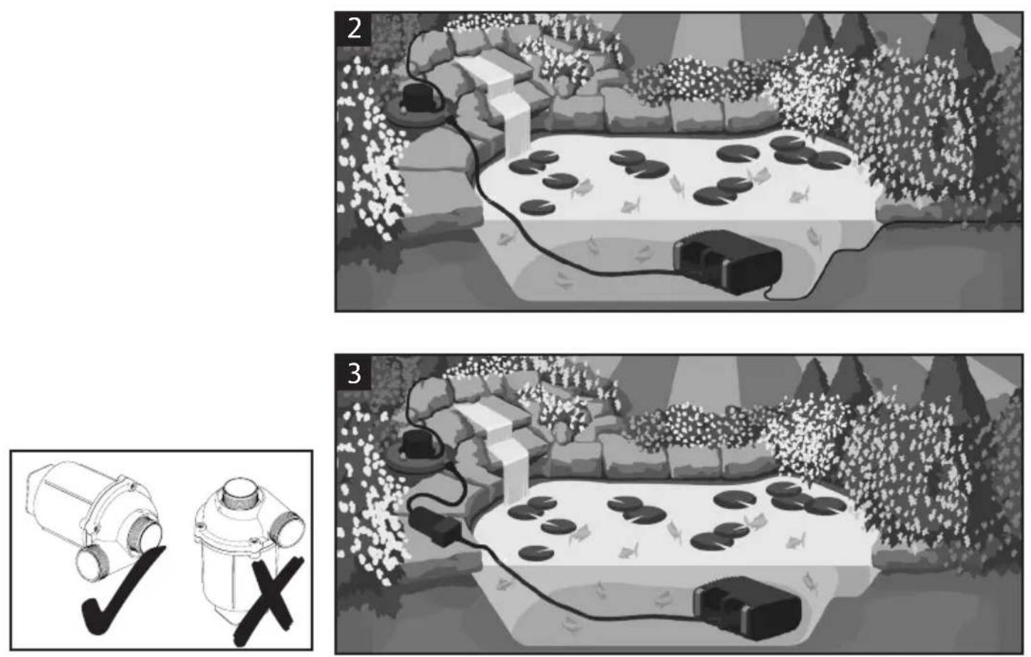
Typical Installation
NOTE: When running amphibiously, the dry sited pump MUST be positioned horizontally, as shown.
(See Fig. 2 & 3)
Pump Assembly & Installation - Submerged Operation
- Open the clips at either end of the strainer cage (Fig 1-F) and open the cage.
- Remove the Small fish protection insert (Fig 1-A).
- Remove & unpack the ball joint, hosetails & Flow control (Fig 1-D,E & H).
- Remove the mains supply cable and unwind.
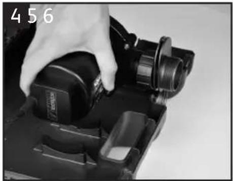
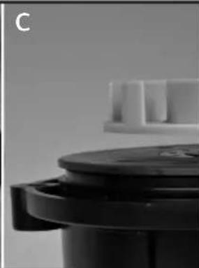
- Ensure that the outlet of the pump is secured to the outlet adaptor (Fig 1 - C). Locate the pump onto its mounting area ensuring that the adaptor piece slots into the location ribs in the front of the lower cage (Fig 4).
Note: The adaptor should be orientated with the outlet at the bottom of the cage (Fig 5).
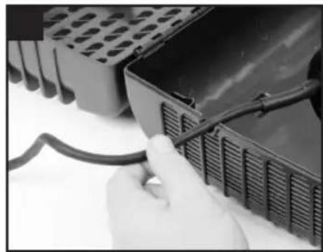
6. Locate the mains supply cable into the recess on the side of the cage. Ensure it is seated in the correct position so that the cable does not get
trapped when the cage is closed. (Fig 6).
Refit the small fish protection insert.
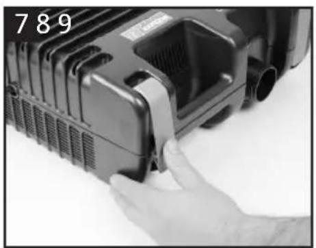
- Close the cage lid ensuring that the end cap (Fig 1 - G) is in its correct position and secure by pressing in the centre of the clips (Fig 7).
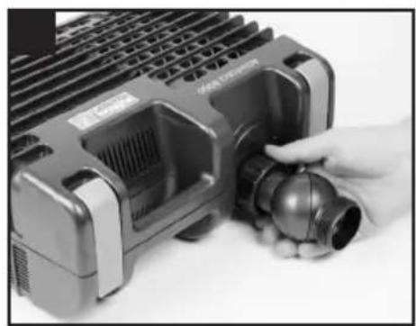
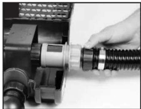
- Checking that the ball joint's inlet and outlet bosses are in line, firmly screw the nut on to the screw thread on the outlet adaptor (Fig 8).
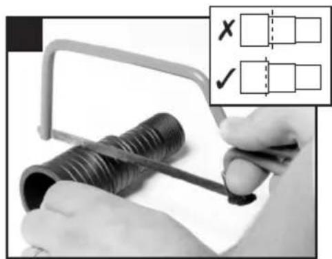
- Using small bore hoses leads to excessive restriction of the water flow. The larger the diameter of hose that you use the better the performance of the pump will be, especially over long hose runs. The hosetail supplied with this unit will accommodate 25mm (1"), 32mm (1.25") and 40mm (1.6") hose as well a 34 BSP screw thread for attaching fountain accessories. We would always recommend that on pumps of this size, that the 40mm diameter hose should be used when using the pump as a waterfall pump or in combination with a filter (Fig 2 & 3). Once you have selected the hose diameter you wish to use, cut the steps off the hosetail which are smaller than the hose diameter to eliminate restriction (Fig 9). Attach a suitable length hose to the hosetail and secure with a suitable hose clip and position the outlet end of the hose in the desired position.
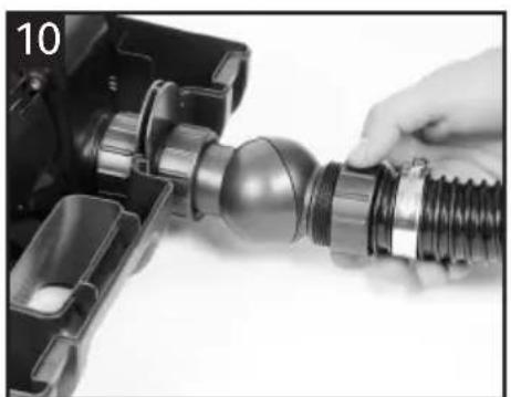
- Screw the hosetail directly onto the outlet boss of the ball joint (Fig 10). The ball joint can be rotated to allow the hose to be directed away from the pump.
Position
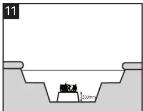
- For the best results, the pump should be positioned in the deepest part of the pond at least 200mm under the surface. This will ensure the best circulation of water in the pond and when being used as a filtration pump, its solids handling capability will be maximised.
For best results, the pump should not be placed directly on the bottom of the pond. We recommend that the pump be installed on a flat level platform which is raised approximately 300mm from bottom of pond. This will prevent the pump sucking dirt directly from the bottom of the pond and will also ensure that sufficient water remains in the pond in the event of accidental leakage of pond water (See Fig 11).
Small Fish Protection Insert
- If you have fish or other wildlife in your pond, there are periods in the year during which they may breed. At this time the fish 'fry' are small and can be sucked into the pump. To minimise this possibility, the Aquaforce range of pumps has a unique small fish protection insert, which reduces the inlet strainer hole size down to 2mm at this critical time in fishes' life cycle. To use this feature, locate the insert's 4 legs into the corresponding area in the lower cage as shown in Fig 12 ensuring
that the insert is the correct way round. Close the top of the cage and secure the clips. Whilst the insert is in use, you may need to unblock the Strainer Cage more frequently. Once the fish or other wildlife have grown to a sufficient size you can then remove the insert from your pump's cage and return the strainer size to its maximum 10mm size.
Using The Flow Control
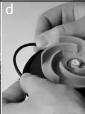
The flow Control (Fig 1 - H) can vary the amount of water entering the pump. Alternatively, it can be used to connect a second inlet to the pump such as a satellite filter or a skimmer. Do not use the flow control when the pump is being used amphibiously.
- Open the cage and remove the end cap (Fig 1 - G).
- Close the flow control by rotating the outer part until the arrows are aligned.
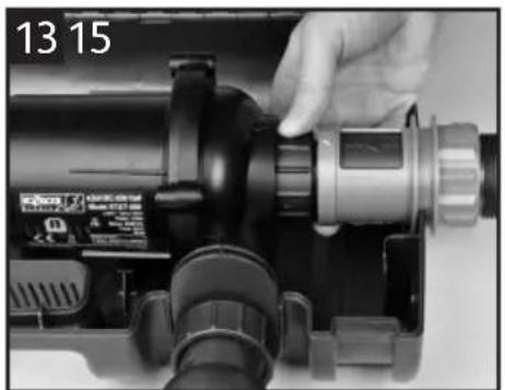
- Firmly screw the flow control to the inlet of the pump aligning the arrows on the flow control with the arrow in the centre of the top of the pump chamber (Fig 13).
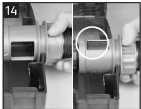
- Locate the pump into the cage. Ensure that the slots in the outlet adaptor align with the ribs in the lower cage and that the grip of the flow control is on the outside of the cage (Fig 14).
- To use as a flow control, screw the end cap to the free end of the flow control.
- Rotate the grip to the desired position. This varies the opening size on the flow control. The arrow on the grip aligns with the pointer on the outside of the top cage.
When the pointed end of the arrow is aligned with the pointer on the outside of the filter cage, this indicates minimum flow. When the wide end of the arrow is aligned with the pointer, this indicates maximum flow (See fig 14).
- Locate the cable into its recess (See point 6 under Submerged Operation), close the cage lid and secure the clips.
- This allows you to reduce the flow of water to your filter and control the waterfall size.
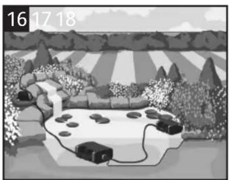
- To use a second inlet connect a suitable length of hose to a hosetail which has been cut to a suitable diameter and screw to the free end of the flow control in place of the end cap (Fig 15).
- The other end of the hose can be connected to a satellite filter (Fig 16) (available as a spare from Hozelock) or to a skimmer (Fig 17).
- By rotating the grip of the flow control, the amount of water coming through the satellite filter or skimmer can be varied.
Pump Assembly & Installation - Amphibious Operation
This pump can be used amphibiously (i.e. it can be used whilst not submerged).
WARNING! Ensure that the unit does not take in air or run dry otherwise your pimp will be damaged.
WARNING! Always unplug or disconnect all appliances in the pond from the electricity supply before putting your hands in the water whilst equipment is being installed, repaired, maintained or handled.
NOTE: This pump does not self prime. The suction hose and pump must be filled with water before switching on.
- Open the clips at either end of the strainer cage, open the cage, and remove all the contents.
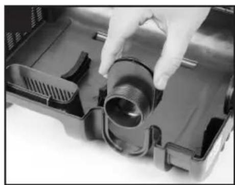
- Unscrew the outlet adaptor from the pump outlet and locate it into the ribs in the lower cage (Fig 18).
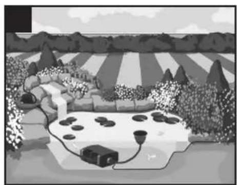
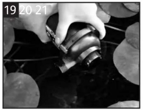
- Place the pump under the surface of the water near the side of the pond to allow water to flow into the pumping chamber (Fig 19).
- Cut 2 hosetails to the required size (See point 9 under Submerged Operation). Attach a suitable length hose to each hosetail and secure with suitable hose clips.
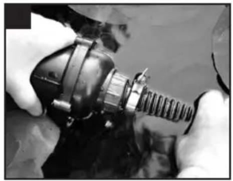
- Submerge the inlet hose under the surface of the water ensuring that the complete hose fills. Screw the hosetail to the inlet of the pump ensuring a watertight seal using the washer provided (Fig 20).
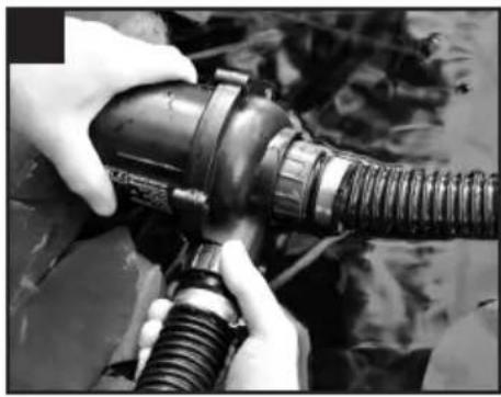
- Fix the outlet hose to the pump outlet by screwing on the hosetail. Ensure a watertight seal using the washer provided (Fig 21).
- Check that the pump chamber and hose are full of water and switch on the pump. The pump can now be removed from the water to its amphibious operating location ensuring that the inlet end of the hose remains submerged.
- To prevent the pump becoming clogged, connect the cage to the inlet end of the inlet hose using another hosetail.
- When using the pump amphibiously, protect the pump from direct sunlight. Direct sunlight may overheat the motor.
- The ball joint is not designed to be used out of water.
Maintenance
The Hozelock Cyprio range of Aquaforce pumps have been designed to allow fast and easy maintenance. To prolong the life of your pump and keep your pump in peak condition, you should follow these maintenance guidelines.
Caution: Always unplug or disconnect ALL appliances in the pond from the electricity supply before putting your hands in the water or starting maintenance.
- When the pump is newly installed, you should check your pump daily that it is performing correctly.
- If you notice a drop in performance (low flow) you should clean the strainer cage. Cleaning intervals will vary depending on the condition of your pond's water. This could be as often as weekly in the summer months. To clean the strainer cage, open the clips and remove the pump. The cage can then be wiped clean of debris blocking the strainer holes and washed in clean water. You should also check that the pump chamber & rotor are not blocked with debris.
- At least once a year you should completely disassemble the pump including the rotor assembly as described below and wash all components in clean, fresh water.
Replace worn or broken parts.
- If you live in a hard water area (water with high levels of calcium or limescale content), the pump, rotor assembly and steel can should be cleaned at regular intervals. The cleaning interval required will vary depending on the hardness of your water, so you should inspect for signs of calcium build up regularly.
To clean off calcium or limescale deposits a small nylon bristled brush (such as a toothbrush) may be used.
Dismantle the pump as described above and remove the rotor. Clean the limescale deposits from the rotor using fresh clean water If excessive calcium deposits build up, the thermal overload protection may be activated (See INTRODUCTION).
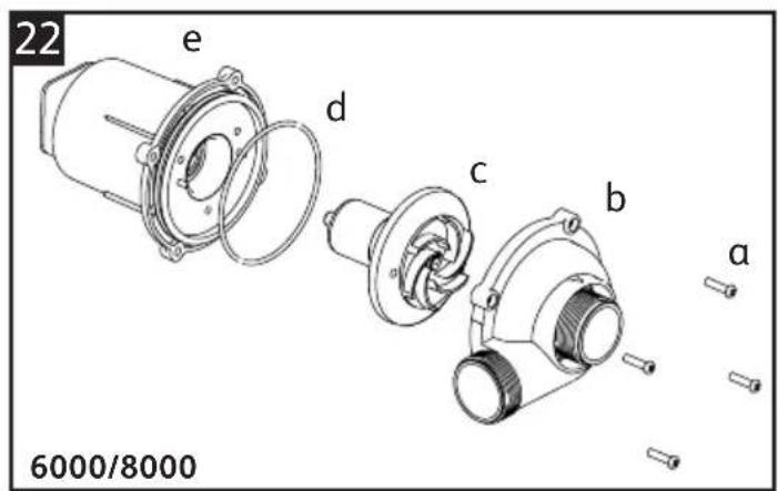
Pump Dismantling & Assembly (6000 & 8000) - Fig 22 & 24
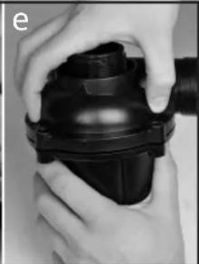
- Switch off the pump and remove the strainer cage as described above and remove the pump.
- Ensure the pump is cool before dismantling it.
- Unscrew the 4 posidrive screws (a) from the chamber.
- Gently pull the pump chamber (b) squarely away from the motor body (e).
- Pull the rotor assembly (c) out of the motor body.
Important! Take extra care so as to not drop the rotor assembly.
- Wash out all of the components in clean water. Do not use detergents or other chemical cleaners.
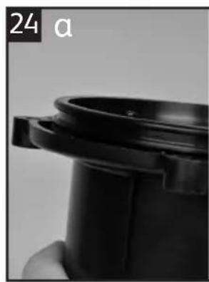
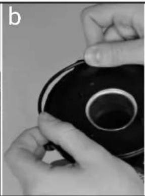
- Ensure the o-ring (d) is in its groove (Fig 24a & 24b).
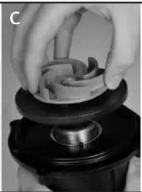
- Replace the rotor assembly into the motor body ensuring that the holes in the plate behind the impeller locate onto the pins on the motor body (Fig 24c & 24d).
- Refit the pump chamber. Twist the chamber to align the screw holes and refit the screws taking
care not to push out the nuts in the motor body (Fig 24e).
- Return the pump to the strainer cage.
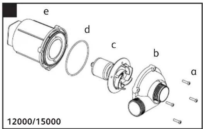
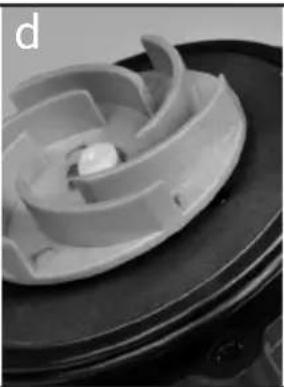
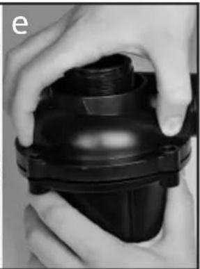
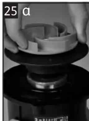
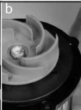
Pump Dismantling & Assembly (12000 & 15000) - Fig 23 & 25
- Switch off the pump and remove the strainer cage as described above and remove the pump.
- Ensure the pump is cool before dismantling it.
- Unscrew the 4 posidrive screws (a) from the chamber.
- Rotate and pull the pump chamber (b) squarely away from the motor body (e).
- Pull the rotor assembly (c) out of the motor body. Important! Take extra care so as to not drop the rotor assembly.
- Wash out all of the components in clean water. Do not use detergents or other chemical cleaners.
- Replace the rotor assembly into the motor body (Fig 25a), ensuring that the holes in the plate behind the impeller locate onto the pins on the motor body (fig 25b).
- Note that the o-ring groove is formed when the rotor has been correctly positioned (Fig 25c). Fit the o-ring (d) over the rotor. Ensure the o-ring is on correctly positioned between the rotor plate and motor body (Fig 25d).
- Refit the pump chamber. Twist the chamber to align the screw holes and refit the screws taking care not to push out the nuts in the motor body (Fig 25e).
- Return the pump to the strainer cage.
Winter Care
- Your pump should be removed from your pond during the autumn.
- Clean the pump as described above.
- During winter, we recommend storing the pump in a bucket of water. This is to prevent the bearings from drying out and potentially seizing. This is especially important if you have been using your pump in a hard water area. The bucket of water containing the pump should be stored in a frost protected area.
Troubleshooting/Fault Finding
Important - Please keep this section for reference. LOW FLOW FROM PUMP
- Ensure that the strainer cage is clean.
- A small diameter outlet pipe will restrict outlet flow.
- Ensure that there is no blockage within the pump chamber.
- If using the pump amphibiously, ensure that the ball joint is not being used and check that the
washers provided are used when fixing the hosetail to the pumps.
NO FLOW FROM PUMP
- Check the power supply is on.
- Check the fuse, RCD and wiring.
- Check that the rotor assembly is not jammed, blocked, damaged or showing signs of excessive wear.
- Ensure that the strainer cage is clean.
- The thermal overload protection has tripped (see INTRODUCTION).
Hozelock Cyprio 3 + 2 Year Guarantee
If this pump, excluding the rotor assembly, becomes unserviceable within 3 years of the date of purchase it will be repaired or replaced at our option free of charge, unless in our opinion it has been damaged or
misused. To extend this guarantee to 5 years please register at http://register.hozelock.com.
Liability is not accepted for damage due to accident, improper installation or use. Liability is limited to replacement of a faulty pump.
This guarantee is not transferable. It does not affect your statutory rights. To obtain the benefits of the guarantee, firstly contact Hozelock Cyprio Consumer Services who may request that the pump is sent along with proof of purchase directly to the address below. Hozelock Cyprio Ltd.
Midpoint Park, Birmingham
B76 1AB. England
Telephone: 0121 313 1122
www.hozelock.com
Performance*
| Aquaforce 1000 2500 4000 60 | 00 8000 120 | 00 15000 | |||||
| Saleable Part Number | 1580 | 1581 | 1582 | 1583A | 1584A | 1585A | 1586A |
| Volts (V) | 230V 50Hz | 230V 50Hz | 230V 50Hz | 230V 50Hz | 230V 50Hz | 230V 50Hz | 230V 50Hz |
| Power (W) | 25 | 30 | 50 | 65 | 95 | 130 | 180 |
| Max Flow, Qmax (I/hr) | 1000 | 2500 | 4000 | 6000 | 8000 | 12000 | 15000 |
| Max Head, Hmax (m) | 1.5 | 2.1 | 2.5 | 3.5 | 4.0 | 5.0 | 5.7 |
| IP Rating | IPX8 | IPX8 | IPX8 | IPX8 | IPX8 | IPX8 | IPX8 |
| Max submersion depth (m) | 2.5 | 2.5 | 2.5 | 2.5 | 2.5 | 2.5 | 2.5 |
| Max Water Temperature, Tmax (℃) | 35°C | 35°C | 35°C | 35°C | 35°C | 35°C | 35°C |
| Amphibious use | × | × | × | ✓ | ✓ | ✓ | ✓ |
*Measured under controlled condition

INSTRUCTIONS AVANT INSTALLATION.
LE NON RESPECT DES INSTRUCTIONS SUIVANTES PEUT ENTRAINER DES BLESSURES, ENDOMMAGER L'APPAREIL OU PROVOQUER LA PERTE DE POISSONS.
CONSERVEZ CES INSTRUCTIONS POUR RÉFERENCE ULTÉRIÉURE.
VOUS POUVEZ ÉGÀLEMENT TÉLÉCHARGER CES INSTRUCTIONS À L'ADRESSE http://www.hozelock.com/customer-service/instruction-leaflets.html.
Contenu
http://www.hozelock.com/customer-service/instruction-leaflets.html
Inhalt
INSTRUKSJONENE PÅ http://www.hozelock.com/ customer-service/instruction-leaflets.html.
Innhold
EM http://www.hozelock.com/customer-service/instruction-leaflets.html.
Conteudo
Do not dispose of electrical appliances as unsorted municipal waste, use separate collection facilities. Contact you local government for information regarding the collection systems available. If electrical appliances are disposed of in landfills or dumps, hazardous substances can leak into the groundwater and get into the food chain, damaging your health and well-being. In the EU, when replacing old appliances with new ones, the retailer is legally obligated to take back your old appliance for disposals at least free of charge.
WEEE
Midpoint Park, Birmingham,
B76 1AB. England
Tel: +44 (0) 121 313 1122
www.hozelock.com
43389-003