Aquaforce 2500 - Pump HOZELOCK - Free user manual and instructions
Find the device manual for free Aquaforce 2500 HOZELOCK in PDF.
| Brand | Hozelock |
| Model | Aquaforce 2500 |
| Category | Submersible pond pump |
| Use | Pond filtration, waterfalls, water features |
| Power supply | 230 V, 50 Hz, 30 W |
| Maximum flow rate | 2500 l/h |
| Maximum delivery head | 2.1 m |
| Maximum particle diameter | 6 mm |
| Maximum water temperature | 35 °C |
| Protection rating | IPX8 |
| Maximum submersion depth | 2.5 m |
| Power cable length | 10 m |
| Thermal protection | Yes, automatic shutdown in case of overheating |
| Aquatic Life Protection System (WPS) | Yes, reduces inlet openings to 2 mm |
| Maintenance | Clean filter cage, annual rotor disassembly, descaling if hard water |
| Main spare parts | Pump chamber assembly Z10006, rotor 1681, outlet adaptor 1682, spherical gasket Z10013, hose connector Z10012 |
| Warranty | 3 years, extendable to 5 years by online registration |
| Country of origin | Not specified |
Frequently Asked Questions - Aquaforce 2500 HOZELOCK
User questions about Aquaforce 2500 HOZELOCK
0 question about this device. Answer the ones you know or ask your own.
Ask a new question about this device
Download the instructions for your Pump in PDF format for free! Find your manual Aquaforce 2500 - HOZELOCK and take your electronic device back in hand. On this page are published all the documents necessary for the use of your device. Aquaforce 2500 by HOZELOCK.
USER MANUAL Aquaforce 2500 HOZELOCK
text_image
ROHS COMPLIANT 2002/95/EC AIRPURANCE 2500 CE
Hozelock Ltd.
Midpoint Park,
Birmingham B76 1AB. England
Tel: +44 (0) 121 313 1122
info@hozelock.com
www.hozelock.com
43388-003

flowchart
graph TD
    A["Person moving in box"] --> B{Question mark?}
    B --> C["Person holding phone"]
    C --> D["HOZELOCK"]

natural_image
Empty white square with black border (no text or symbols)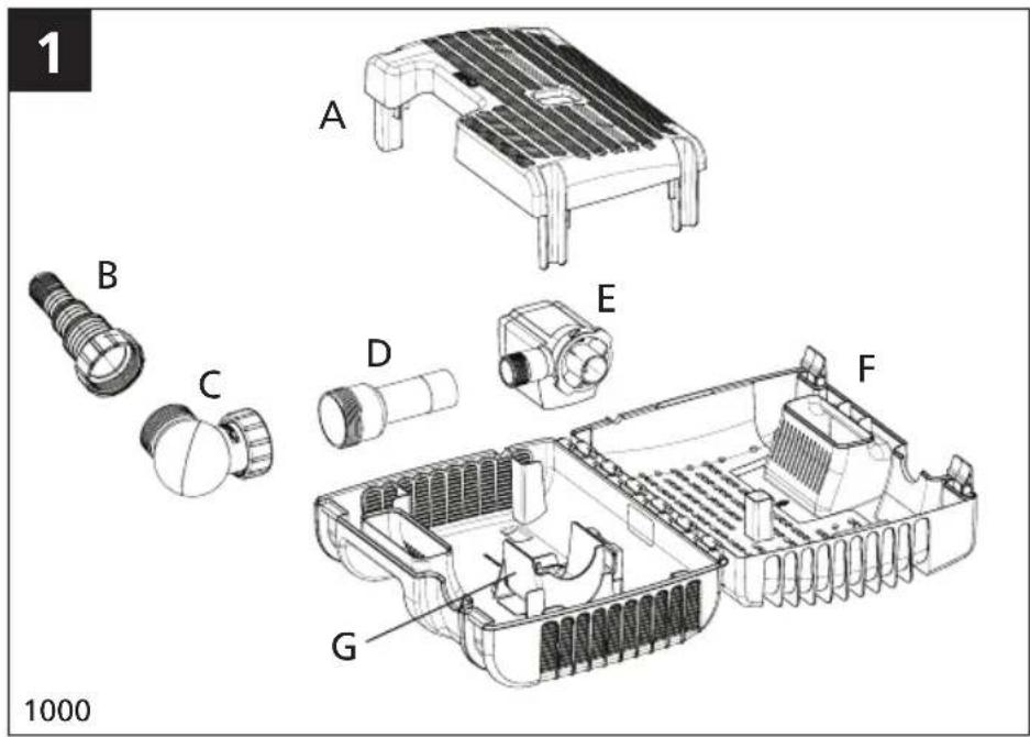
text_image
1 A B C D E F G 1000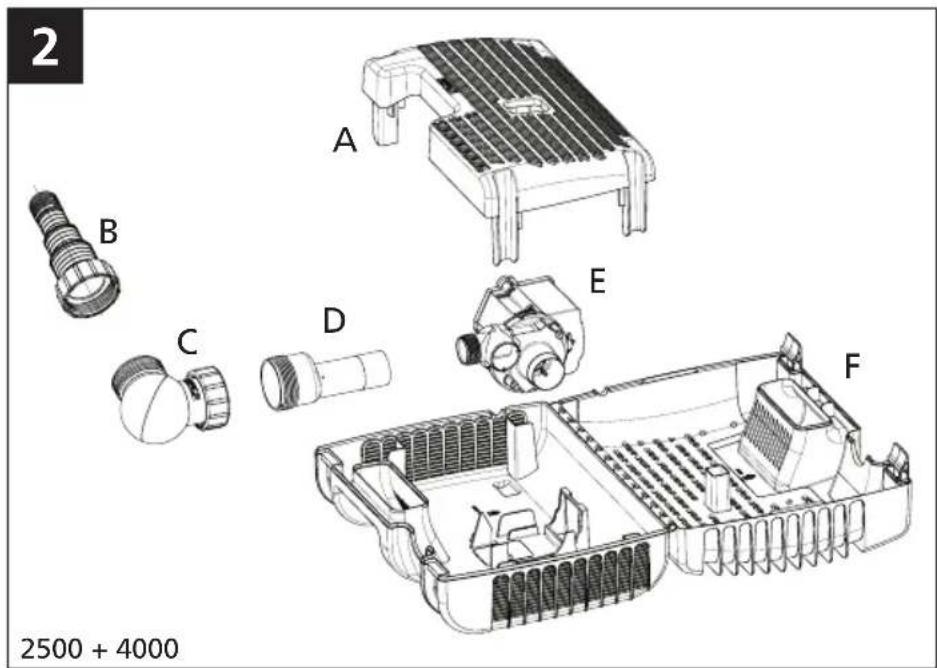
text_image
2 A B C D E F 2500 + 4000
natural_image
Black-and-white illustration of a pond with lily pads, a small container, and surrounding rocks and plants (no text or symbols)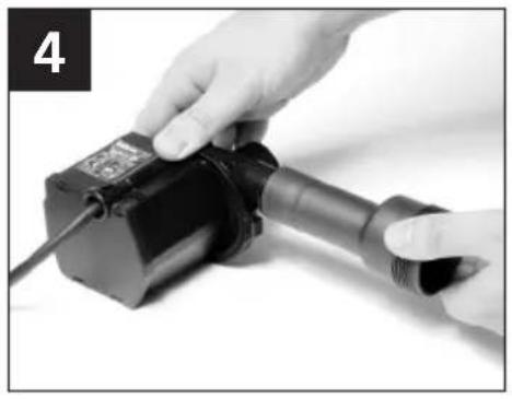
natural_image
Close-up of hands operating a black industrial sensor device with a cable (no visible text or symbols)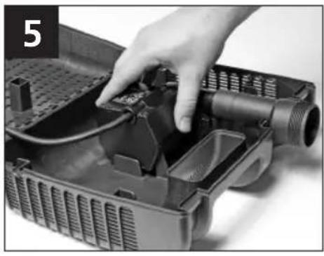
natural_image
Close-up of a hand installing or adjusting a mechanical component into a plastic housing (no visible text or symbols)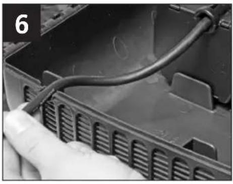
natural_image
Close-up of a hand holding a black cable inserted into a plastic housing (no visible text or symbols)
natural_image
Close-up of a hand pressing down on a mechanical device component (no visible text or symbols)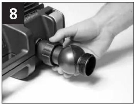
natural_image
Close-up of a hand holding a metallic connector with threaded port (no visible text or symbols)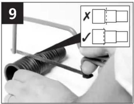
text_image
9 X ✓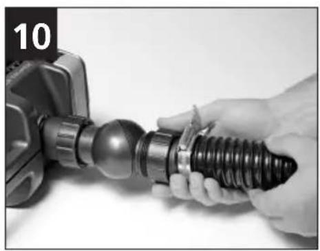
natural_image
Close-up of hands holding a black threaded connector with a mechanical component (no visible text or symbols)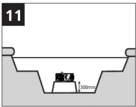
text_image
11 300mm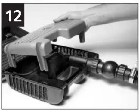
natural_image
Close-up of a robotic device with a hand adjusting a tray, no visible text or symbols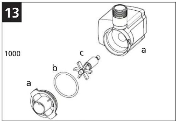
text_image
13 1000 a b c a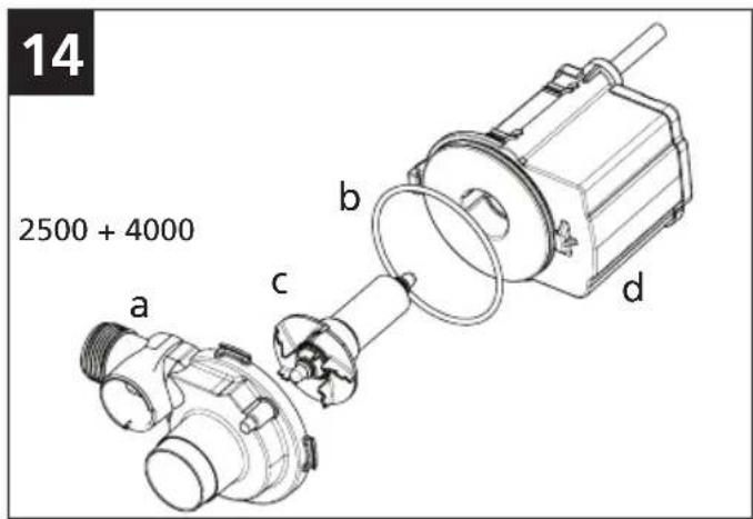
text_image
14 2500 + 4000 a b c d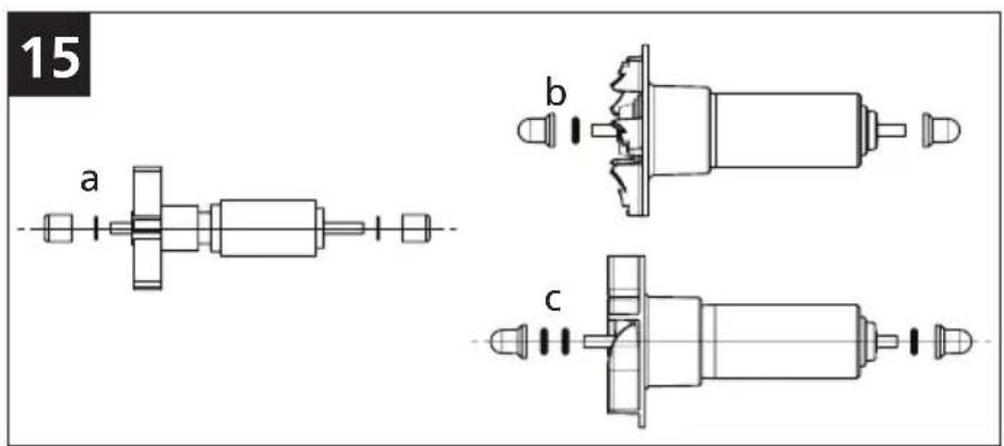
text_image
15 a b cINSTALLATION AND OPERATING INSTRUCTIONS. READ INSTRUCTIONS CAREFULLY BEFORE ATTEMPTING INSTALLATION. KEEP THESE INSTRUCTIONS FOR FUTURE REFERENCE
a. Wildlife Protection system
b. Hosetail & Nut
c. Ball Joint
d. Outlet adaptor
e. Pump
f. Filter Cage
g. Pump cradle (Aquaforce 1000 only)
Introduction
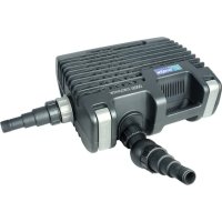
The pump is electrically operated and is designed to pump solid particles up to 6mm in diameter with minimal pre-strainer maintenance.
These types of pumps are particularly suitable for pumping water to external filters or for use in high flow waterfalls or watercourse applications where low maintenance is important. The pump does not use oil or grease for lubrication and can be used safely in ponds containing fish or plants. The motor consists of a sealed stator and water-cooled rotor. All electrical components are isolated from the water.
ATTENTION
AUTOMATIC CUT-OUT
To help ensure your pump's long life and to prevent damage, it is fitted with automatic thermal overload protection. This switches off the pump if it overheats. If this occurs, switch off the power at the mains supply to the pump. Check for the cause. Usually it will be debris blocking the inlets of the pump or obstructing the impeller. Remove the obstruction and wait for the pump to cool down. Then switch on the pump again.
NOTE (AQUAFORCE 2500 & 4000): YOU MUST SWITCH OFF THE MAINS SUPPLY BEFORE THE PUMP WILL RESET.
General Safety Guidelines
Failure to observe the following notices may result in injury, product damage or loss of fish.
-
This pump has been designed for the use with ponds only. Only use this pump for the operation of pond filter systems, water displays, waterfalls etc. Do not use this pump for any other use (i.e. do not use this pump in swimming pools, bathrooms, central heating systems etc). Using the product for any other application may result in injury or product damage.
-
This appliance is not intended for use by persons (including children) with reduced physical, sensory or mental capabilities, or lack of experience and knowledge, unless they have been given supervision or instruction concerning use of the appliance by a person responsible for their safety. Children should be supervised to ensure that they do not play with the appliance. (Australia & NZ only) This appliance is not intended for use by young children or infirm persons unless they have been adequately supervised by a responsible person to ensure that they can use the
appliance safely. Young children should be supervised to ensure that they do not play with the appliance.
-
WARNING: Always unplug or disconnect all appliances in the pond from the electricity supply before putting your hands in the water whilst equipment is being installed, repaired, maintained or handled.
-
Never use the mains supply cable to lift the pump, as this may cause damage. We recommend fitting a lifting cord to the handle on the strainer cage when the pump is installed in deep water.
-
Do not operate or leave the pump in freezing conditions.
-
Protect the pump from direct sunlight. Direct sunlight may overheat the motor.
-
Never allow the pump to run dry.
-
Do not operate this pump without the strainer cage properly attached. Using the pump without the strainer cage may invalidate your warranty.
-
ATTENTION: This product is not suitable for water temperatures above 35°C.
-
ATTENTION: Do not operate this product if the mains supply cable or the motor has become damaged in any way. The supply cable cannot be replaced as it is permanently encased in the motor housing and should therefore be disposed of according to local regulations.
-
If you live in a hard water area (water with high calcium or limescale content), the pump, rotor assembly and inside of motor should be cleaned at regular intervals (See MAINTENANCE).
-
Only use accessories which have been designed for use with this product. The use of any other accessories may invalidate your guarantee.
UK ONLY: Installing this product in the garden is classed as 'notifiable' in the revised Building Regulations for England and Wales. The Regulations require you to tell your local authority building control department that you intend to install this product before installation.
Your local authority will let you know how you can get your installation approved.
Electrical Connections
-
WARNING: Always unplug or disconnect all appliances in the pond from the electricity supply before putting your hands in the water whilst equipment is being installed, repaired, maintained or handled.
-
Check that the voltage marked on the unit corresponds to the mains supply.
-
The pump is supplied with 10m of 3 core electric cable which is permanently connected and sealed to the motor.
The supply cable cannot be replaced. If the cable is damaged, the pump should be discarded.
The plug supplied with this product is not waterproof and must be housed in a dry, waterproof enclosure.
-
A 10mA or 30mA Residual Current Device (RCD) must be fitted to the mains supply.
-
The installation must conform to the National and Local wiring regulations which could include the use of plastic or metal conduit to protect the cable.
-
WARNING: This appliance must be connected to an earthed supply.
-
The pump cable (and extension cable) should be positioned and adequately protected against damage especially where contact with gardening equipment,
(lawn mowers, forks etc..) children and domestic animals may occur.
Typical Installation
(Fig 3)
Pump Assembly & Installation
ASSEMBLY
- Open the clips at either end of the strainer cage and open the cage.
- Remove the Wildlife Protection system (Fig1 - a).
- Remove & unpack the ball joint, hosetails & outlet adaptor (Fig 1 – b, c & d).
- Remove the mains supply cable and unwind.
- Screw the outlet adaptor onto the outlet of the pump. Do not over tighten (Fig 4).
- Locate the pump onto its mounting area ensuring that the outlet adaptor rests in the recess in the lower part of the cage (Fig 5).
Note: 1000 model: The pump locates into a cradle that is fixed to the lower cage (Fig 1 - g).
-
Locate the mains supply cable into the recess on the side of the cage. Ensure it is seated in the correct position so that the cable does not get trapped when the cage is closed. (Fig 6).
-
Close the cage lid and secure by pressing in the centre of the clips (Fig 7).
-
Checking that the ball joint's inlet and outlet bosses are in line, firmly screw the nut on to the screw thread on the outlet adaptor (Fig 8).
-
Using small bore hoses leads to excessive restriction of the water flow. The larger the diameter of hose that you use the better the performance of the pump will be, especially over long hose runs. The hosetail supplied with this unit will accommodate 25mm (1"), 32mm (1.25") and 40mm (1.6") hose as well a 34 BSP screw thread for attaching fountain accessories. We would always recommend that on pumps of this size, that the 40mm diameter hose should be used when using the pump as a waterfall pump or in combination with a filter (Fig 3). Once you have selected the hose diameter you wish to use, cut the steps off the hosetail which are smaller than the hose diameter to eliminate restriction (Fig 9). Attach a suitable length hose to the hosetail and secure with a suitable hose clip and position the outlet end of the hose in the desired position.
-
Screw the hosetail directly onto the outlet boss of the ball joint (Fig 10). The ball joint can be rotated to allow the hose to be directed away from the pump.
Pond Pump Position
- For the best results, the pump should be positioned in the deepest part of the pond.
This will ensure the best circulation of water in the pond and when being used as a filtration pump, its solids handling capability will be maximised.
For best results, the pump should not be placed directly on the bottom of the pond. We recommend that the pump be installed on a flat level platform which is raised approximately 300mm above the bottom of pond. This will ensure that sufficient water remains in the pond in the event of accidental leakage of pond water (See fig 11).
Never use the mains supply cable to lift the pump, as this may cause damage. We recommend fitting a lifting cord to the handle on the strainer cage when the pump is installed in deep water.
Wildlife Protection System (WPS)
- If you have fish or other wildlife in your pond, there are periods in the year during which they may breed. At this time the fish 'fry' are small and can be sucked into the pump. To minimise this possibility, the Aquaforce range of pumps has a unique Wildlife Protection System (WPS), which reduces the inlet strainer hole size down to 2mm at this critical time in fishes' life cycle. To use this feature, locate the WPS's 4 legs into the corresponding area in the lower cage as shown in Fig 12 ensuring that the WPS is the correct way round. Close the top of the cage and secure the clips. Whilst the WPS is in use, you may need to unblock the Strainer Cage more frequently. Once the fish or other wildlife have grown to a sufficient size you can then remove the WPS from your pump's cage and return the strainer size to its maximum 6mm size.
Maintenance
The Hozelock Cyprio range of Aquaforce pumps have been designed to allow fast and easy maintenance. To prolong the life of your pump and keep your pump in peak condition, you should follow these maintenance guidelines.
Caution: Always unplug or disconnect ALL appliances in the pond from the electricity supply before putting your hands in the water or starting maintenance.
- When the pump is newly installed, you should check your pump daily that it is performing correctly.
- If you notice a drop in performance (low flow) you should clean the strainer cage. Cleaning intervals will vary depending on the condition of your pond's water. This could be as often as weekly in the summer months. To clean the strainer cage, open the clips and remove the pump. The cage can then be wiped clean of debris blocking the strainer holes and washed in clean water. You should also check that the pump chamber & rotor are not blocked with debris.
- At least once a year you should completely disassemble the pump including the rotor assembly as described below and wash all components in clean, fresh water. Replace worn or broken parts.
Pump Dismantling & Assembly
(Fig. 13 (1000) - Fig 14 (2500 & 4000))
a. Switch off the pump and remove the strainer cage as described above and remove the pump.
b. Ensure the pump is cool before dismantling it.
c. Release the pump chamber (a) by rotating it until the two retaining tongues are clear of the lugs on the motor body.
d. Gently pull the pump chamber squarely away from the motor body (d).
e. Pull the rotor assembly (c) out of the motor body (d).
Important! Take extra care so as to not drop any of the small components. See Fig 15-a for assembly of the 1000 rotor, Fig 15-b for the assembly of the 2500 rotor and Fig 15-c for assembly of the 4000 rotor.
f. Wash out all of the components in clean water. Do not use detergents or other chemical cleaners.
g. Replace the rotor assembly into the motor body, refit the pump chamber and return the pump to the strainer cage.
4. If you live in a hard water area (water with high levels of calcium or limescale content), the pump, rotor assembly
and the inside of the motor should be cleaned at regular intervals. The cleaning interval required will vary depending on the hardness of your water, so you should inspect for signs of calcium build up regularly.
To clean off calcium or limescale deposits a small nylon bristled brush (such as a toothbrush) may be used. Dismantle the pump as described above and remove the rotor. Clean the limescale deposits from the rotor using fresh clean water.
If excessive calcium deposits build up, the thermal overload protection may be activated (See INTRODUCTION).
Winter Care
- Your pump should be removed from your pond during the autumn.
- Clean the pump as described above.
- During winter, we recommend storing the pump in a bucket of water. This is to prevent the bearings from drying out and potentially seizing. This is especially important if you have been using your pump in a hard water area. The bucket of water containing the pump should be stored in a frost protected area.
Troubleshooting / Fault Finding
Important - Please keep this section for reference.
LOW FLOW FROM PUMP
- Ensure that the strainer cage is clean.
- A small diameter outlet pipe will restrict outlet flow.
- Ensure that there is no blockage within the pump chamber.
NO FLOW FROM PUMP
- Check the power supply is on.
- Check the fuse, RCD and wiring.
- Check that the rotor assembly is not jammed, blocked, damaged or showing signs of excessive wear.
- Ensure that the strainer cage is clean.
- The thermal overload protection has tripped. (see INTRODUCTION).
Hozelock Cyprio 3+2 Year Guarantee
If this pump, excluding the rotor assembly, becomes unserviceable within 3 years of the date of purchase it will be repaired or replaced at our option free of charge, unless in our opinion it has been damaged or misused. To extend this guarantee to 5 years please register at http://register.hozelock.com.
Liability is not accepted for damage due to accident, improper installation or use. Liability is limited to replacement of a faulty pump.
This guarantee is not transferable. It does not affect your statutory rights. To obtain the benefits of the guarantee, firstly contact
Hazelock Cyprio Consumer Services who may request that the pump is sent along with proof of purchase directly to the address below.
Hozelock Cyprio Ltd.
Midpoint Park, Birmingham
B76 1AB. England
Telephone: 0121 313 1122
www.hozelock.com
| SPARE PARTS |
| Contact the Consumer Services Helpline on 0121 313 1122Part NoModel no. 1000 2500 4000 |
| Spares1. Pump Chamber Assembly and Seal. Z10005 Z10006 Z100072. Rotor Assembly. 1680 1681 Z100003. Threaded Outlet Adaptor 1682 1682 16824. Ball Joint Z10013 Z10013 Z100135. Stepped Hosetail & Nut Z10012 Z10012 Z10012 |
| Performance* | |||||||
| Aquaforce | 1000 | 2500 | 4000 | 6000 | 8000 | 12000 | 15000 |
| Saleable Part number | 1580 | 1581 | 1582 | 1583 | 1584 | 1585 | 1586 |
| Volts (V) | 230V 50Hz | 230V 50Hz | 230V 50Hz | 230V 50Hz | 230V 50Hz | 230V 50Hz | 230V 50Hz |
| Power (W) | 25 | 30 | 50 | 65 | 95 | 130 | 180 |
| Max Flow, QMax, (l/hr) | 1000 | 2500 | 4000 | 6000 | 8000 | 12000 | 15000 |
| Max Head, HMax, (m) | 1.5 | 2.1 | 2.5 | 3.5 | 4.0 | 5.0 | 5.7 |
| IP Rating | IPX8 | IPX8 | IPX8 | IPX8 | IPX8 | IPX8 | IPX8 |
| Max submersion depth, (m) | 2.5 | 2.5 | 2.5 | 2.0 | 2.0 | 2.0 | 2.0 |
| Max Water Temperature TMax, (°C) | 35°C | 35°C | 35°C | 35°C | 35°C | 35°C | 35°C |
| Amphibious use | ✗ | ✗ | ✗ | √ | √ | √ | √ |
* Measured under controlled conditions
F

MODE D'EMPLOI POUR L'INSTALLATION ET LE FONCTIONNEMENT. LISEZ CES INSTRUCTIONS
ATTENTIVEMENT AVANT D'ENTREPRENDRE L'INSTALLATION. CONSERVEZ CES INSTRUCTIONS POUR REFERENCE
- Screw the hosetail directly onto the outlet boss of the ball joint (Fig 10). The ball joint can be rotated to allow the hose to be directed away from the pump.
text_image
Warning sign with crossed-out trash bin and prohibition symbolWEEE
Do not dispose of electrical appliances as unsorted municipal waste, use separate collection facilities. Contact you local government for information regarding the collection systems available. If electrical appliances are disposed of in landfills or dumps, hazardous substances can leak into the groundwater and get into the food chain, damaging your health and well-being. In the EU, when replacing old appliances with new ones, the retailer is legally obligated to take back your old appliance for disposals at least free of charge.
WEEE
Midpoint Park, Birmingham B76 1AB. England.
Tel: +44 (0)121 313 1122
www.hozelock.com
The Aquatics Division of Hozelock Group