
Stella 4311 - Barbecue BARBECOOK - Free user manual and instructions
Find the device manual for free Stella 4311 BARBECOOK in PDF.
User questions about Stella 4311 BARBECOOK
0 question about this device. Answer the ones you know or ask your own.
Ask a new question about this device
Download the instructions for your Barbecue in PDF format for free! Find your manual Stella 4311 - BARBECOOK and take your electronic device back in hand. On this page are published all the documents necessary for the use of your device. Stella 4311 by BARBECOOK.
USER MANUAL Stella 4311 BARBECOOK
text_image
QR code image containing encoded data, with a central logo or watermarkGO TO WWW.BARBECOOK.COM, REGISTER YOUR BARBECOOK AND YOUR BARBECOOK EXPERIENCE WILL BE FURTHER IMPROVED!
THIS IS YOUR UNIQUE SERIAL N°
[EN] Go to barbecook.com, register your Barbecook and your Barbecook experience will be further improved!
1 Register your appliance ....6
2 About this manual ....6
3 Important safety instructions ....6
- Read and follow the instructions....6
- Be cautious with gas......6
- Select an appropriate location ....6
• Use your common sense ....6
4 Recurrent concepts....6
- Venturis....6
- Burner hoods....7
- Enamel....7
- Flare-ups ....7
5 Assembling the appliance....7
- Safety instructions....7
• To assemble the appliance....7
6 Connecting gas to the appliance ....7
- Which cylinder, hose and regulator?......7
- Safety instructions......8
- Connecting the hose to the appliance ....8
- Connecting the hose and cylinder to the regulator .....9
- Replacing the cylinder....9
7 Checking for gas leaks....9
• Why check for gas leaks? 9
- When check for gas leaks? 9
- Safety instructions....9
- Which materials do I need?......9
• To check for gas leaks....9
• In case of a gas leak.....10
8 Getting the appliance ready for use....10
- Before each use ....10
• Before first use (in a long time)....10
• Burning in the appliance....10
9 Lighting the burners ....11
- Safety instructions....11
- Lighting the main burners....11
• Lighting the infra-red burner....11 - Switching the burners off ....12
- Relighting the burners ......12
- Checking the flames....12
10 Useful tips and tricks ....13
• Preheating the appliance ....13
• Preventing food from sticking ....13
• Direct and indirect grilling .....13
• Grilling with closed lid....13
- Watching the temperature....13
• Making optimal use of the heat....13
• Taking advantage of the heat zones .....13
- Avoiding flare-ups ....14
11 Maintaining the appliance....14
• Cleaning the grill ....14
• Cleaning the bowl ....14
• Cleaning the burners and venturis....14
- Maintaining enamel, stainless steel and powder coated parts ....15
• Storing the appliance ....15
• Storing gas cylinders....15
• Ordering spare parts ....16
12 Warranty....16
• Covered.....16
• Not covered....16
13 Technical specifications....16
• Type label ....16
- Injector diameters ....16
14 Troubleshooting....17
1 REGISTER YOUR APPLIANCE
Thank you for purchasing a Barbecook appliance! We are sure it will bring you lots of happy barbecue moments.
To optimize your experience, register your appliance at www.barbecook.com. It takes only a few minutes and yields some major benefits:
- You get access to our personalized after sales service. This allows you, for example, to quickly find spare parts for your appliance or to profit from an optimal warranty service.
• We can inform you about interesting product updates and direct you to the product information and specifications that are relevant for your appliance.

For more information about registering your appliance, refer to www.barbecook.com.

Barbecook respects your privacy. Your data will not be sold, distributed or shared with third parties.
2 ABOUT THIS MANUAL
This manual is composed of two parts:
- The first part is the part that you are reading now. It includes instructions for the assembly, use and maintenance of your appliance.
- The second part starts on page 379. It includes all kinds of illustrations (exploded views, assembly drawings...) of the appliances that are described in this manual.
3 IMPORTANT SAFETY INSTRUCTIONS
3.1 Read and follow the instructions
Read the instructions before using the appliance. Always follow the instructions carefully. Assembling or using the appliance differently can cause fires and material damage.

Damages caused by not following the instructions (improper assembly, misuse, inadequate maintenance...) are not covered by the warranty.
3.2 Be cautious with gas
Working with gas is perfectly safe, but requires some extra caution:
- Always store gas cylinders outdoors, in a well-ventilated area. Make sure they are not exposed to excessive heat or direct sunlight.
- Never store your gas cylinder or spare gas cylinder in the cabinet of your appliance.
- While in use, put your gas cylinder in the cylinder cart at the side of the appliance.
- Never store your spare gas cylinder near a gas appliance in use.
• Always turn off the gas supply at the gas cylinder after use. - Never smoke near a gas appliance in use or near a gas cylinder (full/empty).

If you smell gas, immediately close the gas supply, extinguish all flames and open the lid of the appliance. If the smell lasts, call your gas supplier or the fire department.
3.3 Select an appropriate location
Use the appliance outdoors only. Using it indoors, even in a garage or shed, can cause carbon monoxide poisoning.
When selecting an outdoor location, always:
- Place the appliance at least three meters away from any building, in an open and well-ventilated area.
- Make sure there is a free air flow to the burners and the vent holes in the cabinet at all times.
- Make sure the appliance is not under an overhanging structure (a porch, a shelter...) or under foliage.
- Put the appliance on a firm and stable surface. Never put it on a moving vehicle (a boat, a trailer...).
3.4 Use your common sense
Always use your common sense when using the appliance:
- Use outdoors only.
- Do not move the appliance during use.
- Do not leave the appliance unattended during use, especially in the presence of children and animals.
- WARNING! Some accessible parts may become very hot. Keep young children away.
- Use appropriate protection when handling hot parts (lid, grill...).
- The appliance must be kept away from flammable materials during use.
- Keep flammable materials, flammable liquids and dissoluble objects away from an appliance in use.
- Do not use wood, charcoal, lava rocks or ceramic briquettes on a gas appliance.
- Do not use the appliance when you have consumed alcohol or taken drugs.
- Do not modify the appliance.
4 RECURRENT CONCEPTS
This part includes definitions of some less familiar concepts. These concepts are used in several topics of the manual.
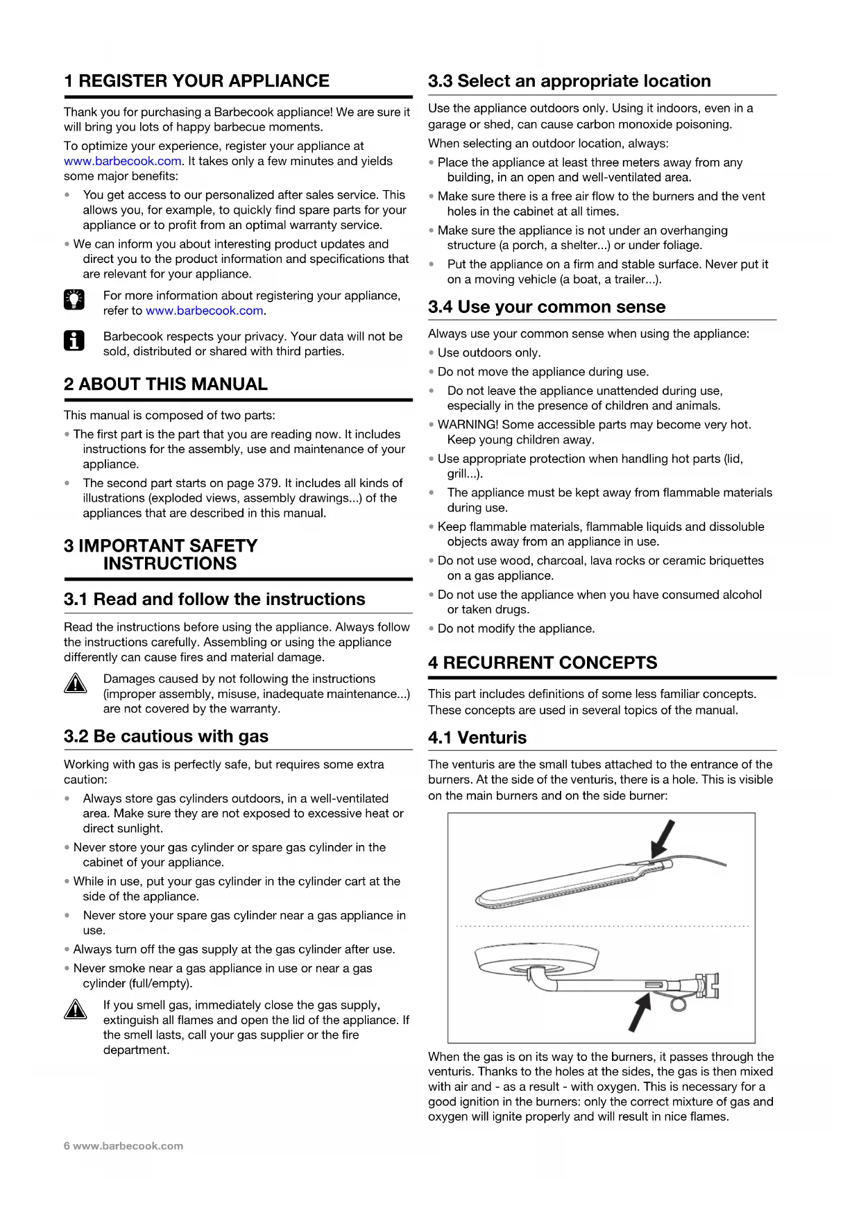
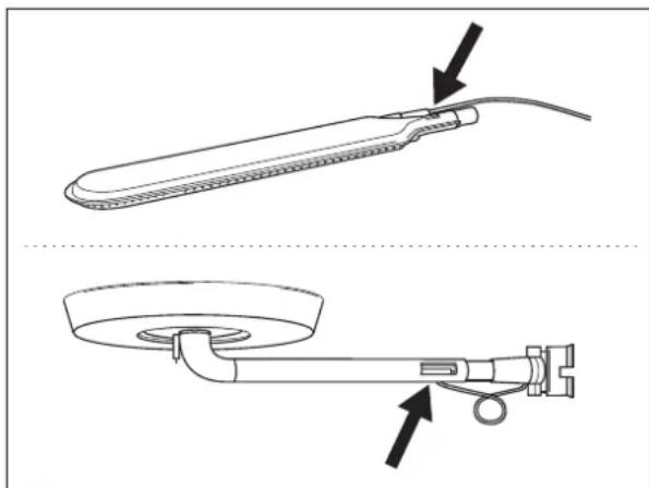
4.1 Venturis
The venturis are the small tubes attached to the entrance of the burners. At the side of the venturis, there is a hole. This is visible on the main burners and on the side burner:
natural_image
Technical line drawing of a medical device with two views: top shows a cylindrical device with cable, bottom shows a circular device with a ring and attached tubing (no text or symbols)When the gas is on its way to the burners, it passes through the venturis. Thanks to the holes at the sides, the gas is then mixed with air and - as a result - with oxygen. This is necessary for a good ignition in the burners: only the correct mixture of gas and oxygen will ignite properly and will result in nice flames.
4.2 Burner hoods
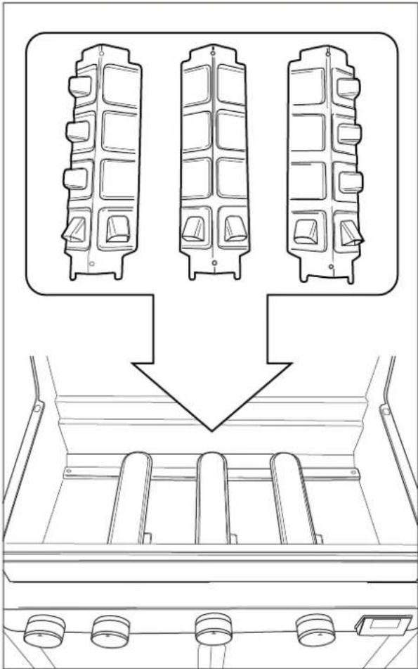
The burner hoods are the hoods that you mount above the burners of your appliance. They protect the burners from dripping fat and play a crucial role in the Turbo Heating System. The roofed holes at the sides of the hoods distribute the heat over the grill, so it is heated much faster and more evenly.

Pay special attention to the burner hoods when assembling your appliance. The Turbo Heating System can only function properly if each hood is mounted above the correct burner.
natural_image
Technical line drawing of a mechanical component with three top views and a downward arrow indicating assembly or disassembly (no text or symbols present)4.3 Enamel
Some parts of the appliance are covered in a layer of melted glass, called enamel. This enamel protects the underlying metal from corrosion. Enamel is a high-quality material: it is resistant to rust, does not fade under the influence of high temperatures and is very easy to maintain.

Because the enamel is less flexible than the metal which it covers, pieces of enamel can chip off when you handle the appliance incorrectly. To avoid problems, be careful when assembling enamelled parts and always maintain the enamel as described further in this manual.
4.4 Flare-ups
Flare-ups are sudden flames that spark from the bowl when you are grilling. They are usually caused by dripping fat or marinade.
5 ASSEMBLING THE APPLIANCE
5.1 Safety instructions
- Do not modify the appliance when assembling it. It is very dangerous and not allowed to alter parts that are pre-assembled and/or sealed by the manufacturer.
• Always follow the assembly instructions carefully. - The user is responsible for the correct assembly of the appliance. Damages caused by improper assembly are not covered by the warranty.
5.2 To assemble the appliance
You need a cross-slotted screwdriver, a flat-slotted screwdriver and an AA battery (electrical igniter). If your appliance comes with a spit burner, you also need two D batteries (spit burner engine). There are no batteries supplied with the appliance.
1 Put the appliance on a flat and clean surface.
2 Assemble the appliance as shown on the assembly drawings. You find them in the second part of this manual, after the exploded view of your appliance.

Be careful when assembling enamelled parts. The tools and screws may damage the enamel. Use the provided fiber washers to protect the enamel around the screws.

The blister packs can contain more screws than necessary. Screws can be left over after the assembly.
6 CONNECTING GAS TO THE APPLIANCE
6.1 Which cylinder, hose and regulator?
Before you can connect gas to the appliance, you have to buy a gas cylinder, hose and pressure regulator. Always buy materials that comply with all national standards and with the gas type(s) and nominal pressure(s) mentioned on the appliance.
The table below shows you which cylinder, hose and regulator you have to use. In Belgium (BE), for example, you have to use a propane cylinder with a hose and regulator for 37 mbar or a butane cylinder with a hose and regulator for 28-30 mbar.
| Country Cylinder, hose and regulator | |
| DK, GR, NO, SE, EE, LT, LV, CZ, PL, MT, HU, SI, SK | Propane, 30 mbar / Butane, 30 mbar |
| ES, GB, IE, PT, BE, FR, LU, IT | Propane, 37 mbar / Butane, 28-30 mbar |
| NL Propane, 30 or 50 | mbar / Butane, 30 mbar |
| CY Propane, 30 or 37 | mbar / Butane, 28-30 mbar |

We recommend connecting the appliance to propane. Propane offers a high-quality combustion and is less sensitive to frost.

Buy your pressure regulator and gas cylinder together. Not all regulators fit all cylinders.
6.2 Safety instructions
- Never connect the cylinder directly to the appliance. Always mount a pressure regulator on the cylinder first.
- Never modify pre-assembled or sealed parts of the cylinder, the hose or the pressure regulator.
- Keep the hose as short as possible (1,5 m maximum) to prevent it from dragging on the ground.
- While connecting the cylinder, hose and pressure regulator:
- Never distort the hose.
- Always keep the cylinder in an upright position.
- Never open the gas supply.
- Check for leaks each time you make changes to the gas connection. See "7 Checking for gas leaks".
6.3 Connecting the hose to the appliance
To connect the gas hose to the appliance, you have to mount a coupling on the gas tube of the appliance. The appliance comes with two couplings, both intended for particular countries:
| Country Coupling | |
| BE, CH, CZ, DK, ES, FI, GB, IE, IT, PT, SI Coupling A | |
| FR Coupling B |

If your country is not in the table, use the coupling that complies with your national standards.

text_image
A B6.3.1 C OUPLING A
You need a 19 mm spanner and a cross-slotted screwdriver.
1 Screw the coupling on the gas tube of the appliance (A) and tighten it with a 19 mm spanner (B).

natural_image
Mechanical diagram showing a bolt and nut assembly with an upward arrow indicating motion (no text or symbols)
natural_image
Mechanical diagram showing a screw being inserted into a housing with a curved arrow indicating rotation (no text or symbols)2 Slide the hose over the coupling (C) and tighten the clamping ring with a cross-slotted screwdriver (D).

natural_image
Mechanical diagram showing a pipe fitting with a threaded connector and an upward arrow indicating motion (no text or symbols)
natural_image
Pure diagram of a pipe fitting with labeled components (no text or symbols)6.3.2 C OUPLING B
You need a 22 mm spanner and an adjustable spanner.
1 Screw the coupling on the gas tube of the appliance (A) and tighten it with a 22 mm spanner (B).

text_image
A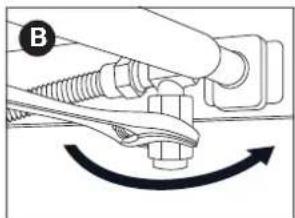
natural_image
Diagram of a hand holding a screw and nut with a curved arrow indicating rotation (no text or symbols)2 Screw the gas hose on the coupling (C) and tighten it with two spanners. Hold the coupling with a 22 mm spanner, while turning the hose with an adjustable spanner (D).

natural_image
Diagram of a mechanical or fluidic device with a valve and fitting, showing no text or symbols.
natural_image
Mechanical diagram showing a lever mechanism with a star symbol and curved arrow indicating rotation (no text or labels)6.4 Connecting the hose and cylinder to the regulator
Depending on the type of pressure regulator you use, you need a cross-slotted screwdriver and/or an adjustable spanner.
1 Connect the hose to the pressure regulator. Do one of the following:
- If the hose has a clamping ring, slide the hose over the regulator and tighten the clamping ring with a cross-slotted screwdriver (A).
- If the hose has a nut, screw the hose on the regulator and tighten the nut with an adjustable spanner (B).

natural_image
Diagram of a mechanical measurement setup with a tool and rotating component (no text or symbols)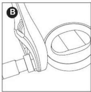
natural_image
Technical line drawing of a mechanical assembly with no visible text or symbols2 Connect the pressure regulator to the gas cylinder. Do one of the following:
- If the regulator has a nut, screw the regulator clockwise on the cylinder and tighten the nut with an adjustable spanner (C).
- If the regulator has a screw thread, screw the regulator counter-clockwise on the cylinder (D).

natural_image
Technical line drawing of a mechanical device with no visible text or symbols
natural_image
Line drawing of a medical or laboratory setup with a device and tubing (no text or symbols)6.5 Replacing the cylinder
1 Close the gas supply and set all control knobs to OFF.
2 Disconnect the empty cylinder and connect the full cylinder.
3 Check the cylinder, the hose and all gas connections for leaks. See "7 Checking for gas leaks".
7 CHECKING FOR GAS LEAKS
7.1 Why check for gas leaks?
Propane and butane are heavier than air. As a result, they do not float away when leaking from the appliance. Especially on windless days, a leak can cause the gas to collect in and around the appliance. That accumulated gas can then ignite and explode.
7.2 When check for gas leaks?
- Before the first use or before the first use after a long period of non-use.

Also check for gas leaks if your appliance was assembled by your dealer.
• Each time you replace a gas component.
- At least once a year, preferably at the beginning of the season.
7.3 Safety instructions
- Put the appliance outdoors, in a well-ventilated area. Make sure there are no flames or heat sources near the appliance.
• Never use a lighter or match to check for gas leaks. - Do not smoke and do not light the burners when checking for gas leaks.
7.4 Which materials do I need?
To check for gas leaks, you need:
- A testing liquid. You can use a ready-made leak spray or a mixture of water (50%) and dish-washing soap (50%).
- The leak test tool that came with your appliance. You use it to suck up the testing liquid and apply it to the gas component or connection that you want to check.

natural_image
Line drawing of a toothbrush with 'barbecook' label on the head (no other text or symbols)7.5 To check for gas leaks
You check for gas leaks by applying a testing liquid to all gas components and connections. If the bubbles on a particular component or connection grow, there is gas leak:

natural_image
Pure mechanical diagram showing a lever and pivot point without any text or symbols
natural_image
Simple line drawing of a hand holding a tool with a cross mark (no text or symbols)To check for gas leaks, proceed as follows:
1 Put the appliance outside.
2 Get your leak test tool and testing liquid (leak spray or water/soap mixture).
3 Open the lid and set all control knobs to OFF.
4 Open the gas supply slightly. Turn the valve of the gas cylinder only once.
5 Suck up some testing liquid with the leak test tool and apply it to the area that you want to check. You have to check:
• The welds of the gas cylinder (A)
• The hose (B)
- The connections between the cylinder and the pressure regulator and between the pressure regulator and the hose (C)
• The connection between the hose and the appliance (D)

natural_image
Line drawing of a gas cylinder with inlet/outlet ports and two arrows indicating flow direction (no text or symbols)
text_image
barbecock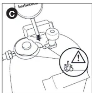
text_image
barbecue C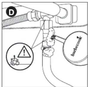
text_image
D batbecookYour pressure regulator and coupling may be different from the ones in the illustrations.
6 Do one of the following:
- If you detect a leak, continue as described in “In case of a gas leak”.
- If there are no leaks, close the gas supply, rinse all components thoroughly with water and dry them well.
7.6 In case of a gas leak
1 Close the gas supply and do one of the following:
- If you detected a leak on one of the connections, tighten that connection.
- If you detected a leak on the cylinder or hose, replace the cylinder or hose.
2 Recheck the connection or component on which you detected the leak.
3 If the leak is not repaired, contact a Barbecook dealer. Do not use the appliance until the leak is repaired.

For a list of nearby Barbecook dealers, refer to www.barbecook.com.
8 GETTING THE APPLIANCE READY FOR USE
8.1 Before each use
Each time you use the appliance, make sure that:
- T he appliance is in an appropriate location. See "3.3 Select an appropriate location".
- The gas hose does not drag on the ground and cannot come into contact with a hot surface or with dripping fat.
- The bowl is clean. We recommend putting a new Leaf® in the bowl before each use. See "11.2 Cleaning the bowl".
- The b urners and venturis are not blocked by insect nests or spider webs. See "11.3 Cleaning the burners and venturis".
-
The appliance is assembled correctly. Pay special attention to:
-
The burner hoods. Each hood has to be placed above the correct burner. See "4.2 Burner hoods".
- The venturis of the burners. They have to be placed over the openings of the gas valves.

natural_image
Diagram of a mechanical component with a shaft and housing, showing a directional arrow (no text or symbols)
If you want to be absolutely sure that your gas connection is okay, you can check your appliance on gas leaks before each use. See "7 Checking for gas leaks".
8.2 Before first use (in a long time)
If you use the appliance for the first time or for the first time after a long period of non-use, you have to execute some extra checks:
- Make sure that you have read, understood and checked all the instructions in this manual (only before first use).
- Check the appliance for gas leaks. See "7 Checking for gas leaks".

Also check for gas leaks if your appliance was assembled by your dealer.
- Clean the burners and venturis (only before first use in a long time). See “11.3 Cleaning the burners and venturis”.
- B urn in the appliance before you put any food on it (only before first use). See "8.3 Burning in the appliance".
8.3 Burning in the appliance
By burning in the appliance before the first use, you remove remaining manufacturing greases from the appliance. Proceed as follows:
1 Light the main burners and set their control knobs to HIGH. See "9.2 Lighting the main burners".
2 Close the lid and let the appliance burn for 15 minutes. Do not put any food on the grill yet.
3 After 15 minutes, open the lid and let the appliance burn for another 5 minutes (control knobs still set to HIGH).
4 After 5 minutes, the appliance is ready for use. You can now put food on the grill.
To light the burners with the electrical igniter, you have to install an AA battery in the igniter. That battery is not supplied with the appliance. You find the battery case of the igniter inside the cabinet of your appliance.
9.1 Safety instructions
- Before you light the appliance, execute all checks listed in "8 Getting the appliance ready for use".
• Make sure the lid is always open when you light a burner. - Never bend directly over a burner when lighting it.
9.2 Lighting the main burners
9.2.1 U SING THE IGNITER
1 Open the lid and set the control knobs of the main burners to OFF.
2 If no other burner is lit yet, open the gas supply and wait ten seconds. This allows the gas to stabilize.
3 Push in the control knob of one burner, set it to HIGH and hold it for a moment. The build-in igniter will cause sparks, which will light the burner.

Always light one main burner to start with. Never light all main burners at the same time.
4 If the burner does not light after three attempts, set its control knob to OFF, close the gas supply and wait 5 minutes. This allows any accumulated gas to escape.
5 Retry lighting the burner. If it still does not light, try lighting it with a match or refer to "14 Troubleshooting" to determine the cause of the problem.
9.2.2 U SING A MATCH
1 Place a match in the match holder.

natural_image
Simple line drawing of a lever with two circular ends and a central dot (no text or symbols)2 Open the lid and set the control knobs of the main burners to OFF.
3 If no other burner is lit yet, open the gas supply and wait ten seconds. This allows the gas to stabilize.
4 Light the match and hold it about 13 mm from the burner.

natural_image
Technical line drawing of a mechanical component with internal compartments and a hanging hook (no text or symbols)5 Set the control knob of one burner to HIGH.

Always light one main burner to start with. Never light all main burners at the same time.
6 If the burner does not light within 5 seconds, set its control knob to OFF, close the gas supply and wait 5 minutes. This allows any accumulated gas to escape.
7 Retry lighting the burner. If it still does not light, refer to "14 Troubleshooting" to determine the cause of the problem.
9.3 Lighting the infra-red burner
9.31 USING THE IGNITER
1 Open the lid and set the control knob of the infra-red burner to OFF.
2 If no other burner is lit yet, open the gas supply and wait ten seconds. This allows the gas to stabilize.
3 Push in the control knob of the infra-red burner, set it to HIGH and hold it for a moment. The build-in igniter will cause sparks, which will light the infra-red burner.
4 If the burner does not light after three attempts, set its control knob to OFF, close the gas supply and wait 5 minutes. This allows any accumulated gas to escape.
5 Retry lighting the infra-red burner. If it still does not light, try lighting it with a match or refer to "14 Troubleshooting" to determine the cause of the problem.
9.3.2 USING A MATCH
1 Place a match in the match holder.
2 Open the lid and set the control knob of the infra-red burner to OFF.
3 If no other burner is lit yet, open the gas supply and wait ten seconds. This allows the gas to stabilize.
4 Light the match and hold it to the left of the infra-red burner.
5 Set the control knob of the infra-red burner to HIGH.
6 If the burner does not light within 5 seconds, set its control knob to OFF, close the gas supply and wait 5 minutes. This allows any accumulated gas to escape.
7 Retry lighting the infra-red burner. If it still does not light, refer to "14 Troubleshooting" to determine the cause of the problem.
9.4 Switching the burners off
If you no longer use the burners, you have to switch them off. Proceed as follows:
1 Close the gas supply.
2 Set the control knobs of the burners to OFF.

By closing the gas supply first, you make sure there is no gas left in the appliance.
9.5 Relighting the burners
If a burner goes out while in use, proceed as follows:
1 Open the lid and close the gas supply.
2 Set all control knobs to OFF and wait 5 minutes. This allows any accumulated gas to escape.
3 Relight the burner(s).
9.6 Checking the flames
Each time you light a burner, you have to check its flames. A perfect flame is almost completely blue, with some yellow at the top. Sporadic yellow flames are normal and not harmful.
If there is something wrong with the flames, do one of the following to solve the problem:
| If the flames are... Do the following... | |
| Low and entirely yellow | 1 Immediately close the gas supply and set all control knobs to OFF.2 Refer to “14 Troubleshooting” to determine the cause of the problem. Most likely, the venturis are blocked. |
| Higher than the bowl | 1 Immediately close the gas supply and set all control knobs to OFF.2 Wait 5 minutes to allow any accumulated gas to escape.3 Relight the burner(s).4 If the problem persists, refer to “14 Troubleshooting” to determine the cause of the problem. |

text_image
LOW HIGH10.1 Preheating the appliance
By preheating your appliance, you make sure the grill is hot enough by the time you put food on it. Proceed as follows:
1 Light the burner(s) and set their control knob(s) to HIGH.
2 Close the lid and leave the appliance for ten minutes.
3 After ten minutes, open the lid and put your food on the grill.
4 If you need less heat now, set the control knob(s) to a lower position.
10.2 Preventing food from sticking
To prevent your food from sticking to the grill:
- Oil the food lightly with a brush before you put it on the grill. You can also oil the grill itself.
- Preheat the appliance. The warmer the grill when you put food on it, the less the food will stick.
- Do not turn the food too quickly. Let it catch some heat first.
10.3 Direct and indirect grilling
Depending on the type of food you are preparing and on how you want to prepare it, you can grill directly or indirectly:
| Method Description Use | ||
| Direct Put your food directly above a lit burner, set that burner to a high position and keep the lid open. | To sear meat and vegetables | |
| Indirect Put your food next to a lit burner, set that burner to a medium/low position and close the lid. | To further cook seared meat | |

When grilling under a closed lid, always keep an eye on the lid thermometer to make sure the appliance does not get too hot. See "10.5 Watching the temperature".
10.4 Grilling with closed lid
Closing the lid while grilling has some important advantages:
- The temperature of the grill is higher and remains more constant.
- You reduce the cooking time of your food and keep your food more moist.
- You reduce flare-ups and save gas.

When grilling under a closed lid, always keep an eye on the lid thermometer to make sure the appliance does not get too hot. See "10.5 Watching the temperature".
10.5 Watching the temperature
Your appliance is equipped with powerful burners, so it heats up rapidly and you can keep the temperature steady. When grilling under a closed lid, however, you have to make sure that the appliance does not get too hot. Keep an eye on the lid thermometer and take into account the following guidelines:
- A normal cooking temperature is about 210^ . At higher temperatures, dripping and accumulated fat can ignite.
- The temperature should never be over 300 °C for more than five minutes. This can damage and deform the appliance.

If the appliance gets too hot, cool it down by opening the lid and setting the burners to a lower position.
10.6 Making optimal use of the heat
The central part of the bowl is hotter than the sides. To allow you to use that hottest part to its full potential, the appliance is equipped with grills of different sizes. It comes with:
• One large grill, to be placed in the centre of the bowl.
- Two smaller grills, to be placed at the sides of the bowl. If you place the grills correctly in the bowl and light all the burners, the entire central grill will be heated to the maximum. Like that, you expand the hottest part of the bowl and you can make optimal use of the grill surface of your appliance.

natural_image
Three identical wire mesh panels arranged horizontally, each with a central slot and two small circular cutouts (no text or symbols)10.7 Taking advantage of the heat zones
When all burners are lit, the burner hoods distribute the heat as evenly as possible over the grill. Despite this even heating, some zones are still hotter than others. You can take advantage of these heat zones to grill your food to perfection:
| Zone Hot? Use to... | ||
| Front Hot | Grill delicate food (prawns, fish...) | |
| Centre | Hotter | Prepare food that needs some time to cook (e.g. sausages, chicken ties...) |
| Back Hottest | Sear meat and vegetables | |

You can also create heat zones by playing with the power of the burners. You can, for example, set a burner to a lower position and use the zone above that burner for delicate food or food that needs some time to cook.
10.8 Avoiding flare-ups
During grilling, some flare-ups are normal. Too many flare-ups, however, increase the temperature in the appliance and can ignite accumulated fat. To avoid flare-ups:
- Make sure the bowl is clean when you start grilling. We recommend putting a new Leaf® in the bowl before each use. See "11.2 Cleaning the bowl".
- Regularly check if the fat drain hole is not blocked and if the fat drip tray or cup is not full yet.
- When grilling fatty meat, trim excess fat, close the lid and set the burners to a medium or low position.
11 MAINTAINING THE APPLIANCE
11.1 Cleaning the grill
We recommend cleaning the grill after each use, with the Barbecook cleaner. Proceed as follows:
1 Spray the foam on the grill and let it act for a while.
The foam discolours, as it soaks off the dirt and greases.
2 Remove the foam with a soft sponge and water and rinse the grill thoroughly.
3 Dry the grill well and store it in a dry place. This prevents formation of rust.

You can also clean the grill with a soft detergent or with sodium bicarbonate. Never use oven cleaners on the grill.
11.2 Cleaning the bowl
We recommend cleaning the bowl after each use. The easiest way to do this is by putting a Leaf ^® in the bowl before you start grilling. The Leaf ^® is a foil that fits the bowl perfectly and that catches all residues and greases. When the appliance cooled down, just remove the Leaf ^® and the bowl is clean.

Register your appliance at www.barbecook.com to find out which type of Leaf® you need.
11.3 Cleaning the burners and venturis
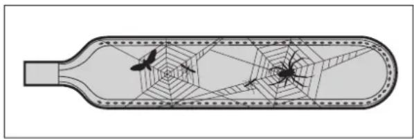
11.3.1 WHY CLEAN THE BURNERS AND VENTURIS?
Spiders and insects can make webs and nests in the burners and venturis. This may block the gas supply to the burners. As a result:
- You cannot light the burners. If you manage to light them anyway, they will only produce smoky and yellow flames.
- The gas can start burning outside the venturis, at the control knobs. These fires are called flash-backs and can result in serious injuries and material damage.
natural_image
Diagram of a bottle with spiderweb and spider inside, showing internal structure (no text or labels)
Damages caused by blocked burners and venturis are regarded as inadequate maintenance and are not covered by the warranty.
11.3.2 WHEN CLEAN THE BURNERS AND VENTURIS?
You have to clean the burners and venturis of your appliance:
- Before the first use after a long period of non-use.
- At least twice a year, of which once at the beginning of the season.
11.3.3 TO CLEAN THE BURNERS AND VENTURIS
1 Remove the burners from the appliance as shown on the illustrations. If you notice that a burner is damaged, you have to replace it.

natural_image
Technical diagram of a car gear shift lever with wrench and nut (no text or symbols)
natural_image
Technical line drawing of a mechanical assembly with directional arrows indicating motion (no text or symbols)
natural_image
Technical line drawing of a mechanical assembly with three curved components and rotational arrows indicating motion (no text or symbols)2 Clean the burners and venturis with a small brush or a homemade pipe cleaner (an unfolded paperclip, a pipe brush...).
3 Put the burners back. Make sure to place the venturis over the openings of the gas valves.
11.4 Maintaining enamel, stainless steel and powder coated parts
The appliance is composed of enamelled, stainless steel and powder coated parts. Each material has to be maintained differently:
| Material How to maintain this material | |
| Enamel | Do not use sharp objects and do not knock against a hard surface.Avoid contact with cold liquids while still hot.You can use metal sponges and abrasive detergents. |
| Material How to maintain this material | |
| Stainless steel | Do not use aggressive, abrasive or metal detergents.Use soft detergents and let them act on the steel.Use a soft sponge or cloth.Rinse thoroughly after cleaning and dry well before storing. |
| Powder coated | Do not use sharp objects. Use soft detergents and a soft sponge or cloth.Rinse thoroughly after cleaning and dry well before storing. |

To prevent formation of rust on stainless steel, avoid contact with chlorine, salt and iron. We recommend not using the appliance near the coast, near railways or near swimming pools.

Damages caused by not following these instructions are regarded as inadequate maintenance and are not covered by the warranty.
Below the exploded view of your appliance (second part of the manual), you find a list with all parts of which the appliance is composed. This list includes a symbol that specifies the material of each part, so you can use it to check how you have to maintain a particular part. The parts list uses the following symbols:
| Symbol Material | |
| ● | Enamel |
| ■ | Stainless steel |
| ★ | Powder coated |
11.5 Storing the appliance
If you do not use your appliance for a longer period of time, store it in a dry place. Before you store the appliance:
- Disconnect the gas cylinder. Never store your appliance indoors (not even in a garage or shed) as long as it is connected to the gas cylinder.
- Clean the burners and the grills, rub them with oil and wrap them in paper.
- If your appliance is equipped with a spit burner, remove the spit burner engine and store it in a dry place.
- Cover your appliance with a Barbecook cover. Register your appliance at www.barbecook.com to find out which cover you need.
11.6 Storing gas cylinders
These instructions apply to both empty and full gas cylinders.
- Always store gas cylinders outdoors, in a well-ventilated area. Make sure they are not exposed to excessive heat or direct sunlight.
- Never store a gas cylinder in an area that can become very hot (in a car, on a boat...).
- Never store your gas cylinder or spare gas cylinder in the cabinet of your appliance.
- Never store your spare gas cylinder near a gas appliance in use.
• Always store gas cylinders outside the reach of children.
• Always store and transport gas cylinders in upright position.
11.7 Ordering spare parts
Parts that are directly exposed to fire or intense heat have to be replaced from time to time. To order a spare part:
1 Look up the reference number of the part you need. You find a list of all reference numbers below the exploded views in the second part of this manual and on www.barbecook.com.

If you registered your appliance online, you will automatically be guided to the correct list.
2 Order the spare part at your point of sale. You can order parts both under and outside warranty.
12 WARRANTY
12.1 Covered
Your appliance comes with a warranty of two years, starting from the date of purchase. This warranty covers all manufacturing defects, provided that:
- You used, assembled and maintained your appliance according to the instructions in this manual. Damages caused by misuse, incorrect assembly or inadequate maintenance are not regarded as manufacturing defects.
- You can present the receipt and the unique serial number of your appliance. This serial number starts with a G, followed by 15 digits. You can find it:
- On this manual and on the starter pack that included the manual.
- On the packaging of the appliance.
- On the type label on the inside of the cabinet door.
- The Barbecook quality department confirms that the parts are defective and that they proved defective under normal use, correct assembly and adequate maintenance.
If one of the above conditions is not met, you cannot claim any form of contribution. In all cases, the warranty is limited to the repair or replacement of the defective part(s).
12.2 Not covered
The following damages and defects are not covered by the warranty:
- Normal wear and tear (rusting, distortion, discolouration...) of parts that are directly exposed to fire or intense heat. It is normal to replace these parts from time to time.
- Visual irregularities that are inherent to the manufacturing process. These irregularities are not regarded as manufacturing defects.
- All damages caused by inadequate maintenance, incorrect storage, improper assembly or modifications made to pre-assembled parts.
- All damages caused by misuse and abuse of the appliance (not using it according to the instructions in this manual, using it for commercial purposes...).
- All consequential damages caused by careless or non-compliant use of the appliance.
- Rust or discolouration caused by external influences, the use of aggressive detergents, exposure to chlorine... These damages are not regarded as manufacturing defects.
13 TECHNICAL SPECIFICATIONS
13.1 Type label
The type label lists all the technical specifications of your appliance. You can find it:
• In the second part of this manual.
- On the inside of the cabinet door.
13.2 Injector diameters
• Main burner: 0,89 mm
• Infra-red burner: 0,82 mm
| Problem Probable cause(s) Solution(s) | ||
| Not enough heat | Gas supply not openVenturis not placed over openings of gas valvesBurner openings blockedGas cylinder (almost) emptyPressure regulator not connected correctly to cylinder and/or hose | Open gas supplyPlace venturis over openings of gas valvesClean burner openings or replace burnersReplace gas cylinderReconnect pressure regulator to cylinder and/or hose |
| Excessive heat and/or flare-ups | Food too fattyFat drain hole blocked, fat in bowl and/or fat on burnersBurner hoods not mounted correctlyTemperature too high | Trim excess fat or set burners to a low positionClean fat drain hole, bowl and burnersMount burner hoods correctlySet burners to a lower temperature and/or grill food indirectly |
| Heat not distributed evenly over grill surface | Some heat differences are normal, see “11.6 Making optimal use of the heat” and “11.7 Taking advantage of the heat zones”. Probable cause(s) for big heat differences:Burners hoods not mounted correctlyAppliance not preheated | Mount burner hoods correctlyPreheat appliance |
| Yellow flames | Burners or venturis blockedSalt on burnersAppliance connected to butane | Clean burners and venturisClean burnersConnect appliance to propane, using an appropriate pressure regulator |
| Incomplete flame Burner blocked | pierced or rusted Clean or replace burner | |
| Flash-backs (flames outside venturis/at control knobs) | Burners or venturis blocked | 1 Close gas supply and set burners to OFF.2 Let appliance cool down.3 Clean burners and venturis. |
| Flames higher than edge of bowl | Lots of windGas cylinder (almost) emptyFat in bowl and/or on burners | Put appliance with rear side towards windReplace gas cylinderClean bowl, clean burners and replace Leaf ^® |
| Pressure regulator hums | Hot weatherNew (full) gas cylinder | Not a hazard or defect. Should stop automatically after a while. |
| Burner whistles when set to LOW | Gas injector, venturi and/or burner dirty Clean gas injector, venturi and burner | |
| Impossible to light burner (using either igniter or match) | Burner or venturi blockedNo gas supply | Clean burner and venturiOpen gas supply and press safety knob on pressure regulator (not present on all regulators) |
| Impossible to light burner with igniter | No battery installed or battery not installed correctlyIgniter wiring not mounted correctlyElectrode damagedFaulty groundFaulty igniter | (Re)install battery, with terminals positioned correctlyCheck and re-assemble all igniter connectionsReplace electrodeCheck and re-assemble electrodes, burners and igniterReplace igniter |
| No sparks nor sound when pressing igniter | No battery installed or battery not installed correctlyEmpty batteryIgniter button not assembled correctlyFaulty spark generator | (Re)install battery, with terminals positioned correctlyReplace batteryRe-assemble igniter buttonReplace spark generator |
natural_image
Technical line drawing of a medical device with two views: top shows a curved tube, bottom shows a circular component with a handle (no text or symbols)natural_image
Technical line drawing of a mechanical component with three top views and a base view (no text or symbols)4.3 Email
natural_image
Mechanical diagram showing a bolt and nut assembly with an upward arrow indicating motion (no text or symbols)
natural_image
Mechanical diagram showing a screw being inserted into a housing with an arrow indicating rotational motion (no text or symbols)natural_image
Technical diagram of a mechanical assembly with a threaded pipe and valve, showing an upward force arrow (no text or symbols present)
text_image
D C6.3.2 K OPPELING B
natural_image
Diagram of a mechanical assembly with a threaded pipe and valve, showing an upward arrow (no text or symbols present)
natural_image
Mechanical diagram showing a lever mechanism with a curved arrow indicating rotational motion (no text or symbols present)natural_image
Mechanical assembly diagram showing a valve and fitting with an upward arrow indicating motion (no text or symbols)
natural_image
Mechanical diagram showing a valve mechanism with rotating components and a star symbol (no text or labels)natural_image
Technical line drawing of a mechanical assembly with a tool and ring component (no text or symbols)
natural_image
Technical line drawing of a mechanical assembly with no visible text or symbolsnatural_image
Technical line drawing of a mechanical assembly with no visible text or symbols
natural_image
Line drawing of a mechanical device with a circular component and a rectangular housing (no text or symbols)natural_image
Line drawing of a bathtub with a handle and textured body (no text or symbols)7.5 Controleren op gaslekken
natural_image
Line drawing of a mechanical component with a circular mark and a checkmark, no text or symbols present
natural_image
Simple line drawing of a mechanical or biological structure with no visible text, numbers, or symbols.natural_image
Line drawing of a gas cylinder with two arrows indicating direction (no text or symbols)
text_image
barbecue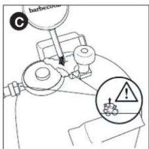
text_image
barbecue C
text_image
D ! barbecownatural_image
Diagram of a mechanical component with a lever and directional arrow (no text or symbols)
natural_image
Simple line drawing of a lever with two circular ends and a central dot (no text or symbols)natural_image
Technical line drawing of a mechanical component with internal compartments and a black arrow indicating a directional change (no text or symbols)natural_image
Three identical wire mesh panels arranged horizontally, each with a central slot and two small circular cutouts (no text or symbols)10.7 De warmtezones benutten
natural_image
Diagram of a bottle with spiderweb pattern and two small insects inside (no text or labels)
natural_image
Diagram of a car interior showing a lever mechanism with a wrench and screwdriver (no text or symbols)
natural_image
Technical line drawing of a mechanical component with directional arrows indicating motion (no text or symbols)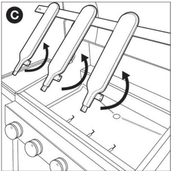
natural_image
Technical line drawing of a mechanical assembly with three curved components and directional arrows indicating motion (no text or symbols)natural_image
Technical line drawing of a medical device with two views: top shows a cylindrical device with a cable, bottom shows a circular device with a handle and connector (no text or symbols)natural_image
Technical line drawing of a mechanical component with three top views and a base view (no text or symbols)4.3 Émail
natural_image
Mechanical assembly diagram showing a bolt and nut assembly with an upward arrow indicator (no text or symbols)
natural_image
Mechanical diagram showing a screw being inserted into a housing with an arrow indicating rotational motion (no text or symbols)natural_image
Diagram of a mechanical assembly with a threaded pipe and a vertical rod, showing an upward arrow (no text or symbols present)
text_image
D C6.3.2 M ANCHON B
natural_image
Diagram of a mechanical assembly with a threaded pipe and valve, showing an upward arrow (no text or symbols present)
natural_image
Mechanical diagram showing a lever mechanism with a curved arrow indicating rotational motion (no text or symbols present)natural_image
Mechanical assembly diagram showing a connector with threaded shaft and valve, no text or symbols present
natural_image
Mechanical diagram showing a lever mechanism with a star symbol and curved arrow indicating rotation (no text or labels)natural_image
Diagram of a mechanical measuring tool interacting with a cylindrical component (no text or symbols visible)
natural_image
Technical line drawing of a mechanical assembly with no visible text or symbolsnatural_image
Technical line drawing of a mechanical assembly with no visible text or symbols
natural_image
Line drawing of a mechanical device with a circular component and lever (no text or symbols)natural_image
Line drawing of a bamboo-cook matchbox with a wooden stick (no text or symbols)natural_image
Line drawing of a pipe joint with a checkmark indicating a detail (no text or symbols present)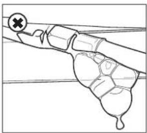
natural_image
Simple line drawing of a hand holding a small object, with no text or symbols present.natural_image
Line drawing of a gas cylinder with inlet/outlet ports and two arrows indicating flow direction (no text or symbols)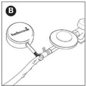
text_image
barbecock B
text_image
barbecue C
text_image
D ! barbecownatural_image
Diagram of a mechanical component with a shaft and housing, showing a directional arrow (no text or symbols)
natural_image
Simple line drawing of a lever with two circular ends and a central dot (no text or symbols)natural_image
Technical line drawing of a mechanical component with internal compartments and a black arrow indicating a directional change (no text or symbols)natural_image
Three identical wire mesh panels arranged horizontally, each with a central slot and two small circular cutouts (no text or symbols)natural_image
Diagram of a bottle with spiderweb pattern inside, showing internal structure (no text or symbols)
natural_image
Technical line drawing of a mechanical assembly with a wrench and screwdriver (no text or symbols)
natural_image
Technical line drawing of a mechanical assembly with directional arrows indicating motion (no text or symbols)
natural_image
Technical line drawing of a mechanical assembly with three curved components and directional arrows indicating motion (no text or symbols)natural_image
Technical line drawing of a medical device with two views: top shows a tool inserted into a tube, bottom shows a mechanical component with a knob (no text or symbols)natural_image
Technical line drawing of a mechanical component with three top views and a base view (no text or symbols)4.3 Emaille
natural_image
Diagram of a mechanical assembly with a threaded component and an upward arrow indicating motion (no text or symbols)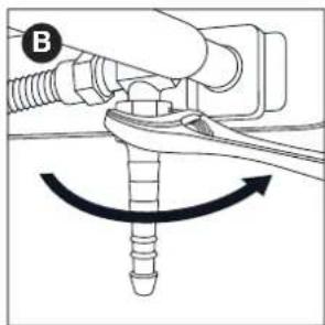
natural_image
Mechanical diagram showing a screw being inserted into a housing with a curved arrow indicating rotation (no text or symbols)natural_image
Technical diagram of a mechanical assembly with no visible text or symbols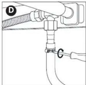
text_image
D C6.3.2 A NSCHLUSS B
natural_image
Diagram of a mechanical assembly with a threaded pipe and valve, showing an upward force arrow (no text or symbols)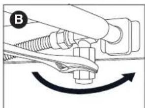
natural_image
Mechanical diagram showing a hand connecting a bolt to a connector with a curved arrow indicating rotation (no text or symbols)natural_image
Mechanical assembly diagram showing a connector with threaded shaft and valve, no text or symbols present
text_image
Diagram showing mechanical assembly with labeled component D and rotation arrownatural_image
Diagram of a mechanical measurement setup with a pipette and rotating component (no text or symbols)
natural_image
Technical line drawing of a mechanical assembly with a circular component and a handle (no text or symbols)natural_image
Technical line drawing of a mechanical assembly with no visible text or symbols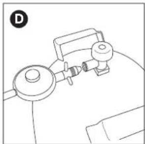
natural_image
Line drawing of a mechanical device with a circular component and a rectangular housing (no text or symbols)natural_image
Line drawing of a toothpaste brush with 'barbecook' label on the head (no other text or symbols)natural_image
Pure mechanical diagram showing a lever mechanism with no text or symbols
natural_image
Simple line drawing of a mechanical component or tool with no visible text, numbers, or symbols.natural_image
Line drawing of a gas cylinder with two arrows indicating direction (no text or symbols)
text_image
barbecue B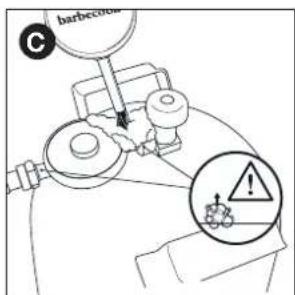
text_image
barbecue C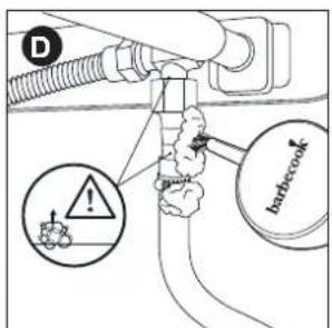
text_image
D barbecooknatural_image
Diagram of a mechanical component with a shaft and housing, showing a directional arrow (no text or symbols)
natural_image
Simple line drawing of a lever with two circular ends and a central pivot point (no text or symbols)natural_image
Technical line drawing of a vehicle battery pack with internal compartments and a black arrow indicating a component (no text or symbols)natural_image
Three identical wire mesh panels arranged horizontally, each with a central slot and two small circular cutouts (no text or symbols)natural_image
Diagram of a bottle with internal spiderweb structure and two insect-like figures (no text or labels)
natural_image
Technical line drawing of a mechanical assembly with a wrench and screwdriver (no text or symbols)
natural_image
Technical line drawing of a mechanical component with directional arrows indicating motion (no text or symbols)
natural_image
Technical line drawing of a mechanical assembly with three curved components and rotational arrows indicating motion (no text or symbols)natural_image
Technical line drawing of a medical device with two views: top shows a cylindrical device with internal structure, bottom shows a circular device with a handle and connector (no text or symbols)text_image
Technical diagram showing three mechanical components with a downward arrow indicating assembly or disassembly process.4.3 Esmalte
natural_image
Diagram of a mechanical assembly with a threaded component and an upward arrow, no text or symbols present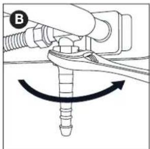
natural_image
Mechanical diagram showing a hand adjusting a screw with a curved arrow indicating rotation (no text or symbols)natural_image
Mechanical diagram showing a threaded fastener inserted into a pipe with an upward arrow indicating force (no text or symbols present)
natural_image
Pure diagram of a pipe fitting with a valve and connector (no text or symbols)6.3.2 A COPLAMIENTO B
natural_image
Mechanical diagram showing a fastener or clamp mechanism with rotational arrow (no text or symbols)natural_image
Diagram of a mechanical valve assembly with a threaded connector and directional arrow (no text or labels)
natural_image
Diagram of a mechanical assembly with a valve and rotating component (no text or symbols)natural_image
Diagram of a mechanical device with a spring scale and labeled section A (no text or symbols present)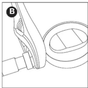
natural_image
Technical line drawing of a mechanical assembly with no visible text or symbolsnatural_image
Technical line drawing of a mechanical assembly with no visible text or symbols
natural_image
Line drawing of a medical or laboratory device with no visible text, numbers, or symbols6.5 Sustituir la bombona
natural_image
Line drawing of a decorative lamp with 'barbecook' text on the lid (no other text or symbols)7.5 Para comprobar si hay fugas de gas
natural_image
Line drawing of a hand holding a tool with a circular checkmark (no text or symbols)
natural_image
Diagram of a hand holding a tool with a cross mark and a circular symbol (no text or labels)natural_image
Line drawing of a gas cylinder with inlet/outlet ports and two arrows indicating flow direction (no text or symbols)
text_image
B barbecue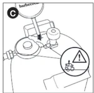
text_image
barbecue C
text_image
D barbecooknatural_image
Diagram of a mechanical component with a lever and shaft, showing directional movement (no text or symbols)natural_image
Simple line drawing of a lever with two circular ends and a central dot (no text or symbols)natural_image
Technical line drawing of a vehicle battery pack with an arrow indicating the direction (no text or symbols present)natural_image
Three identical wire mesh panels arranged horizontally, each with a central slot and small circular cutouts (no text or symbols)natural_image
Diagram of a bottle with spiderweb structure and two butterflies inside (no text or labels)
natural_image
Technical diagram of a mechanical assembly with a tool and spring, no visible text or symbols
natural_image
Technical line drawing of a mechanical assembly with directional arrows indicating motion (no text or symbols)
natural_image
Technical line drawing of a mechanical assembly with three curved components and rotational arrows indicating motion (no text or symbols)natural_image
Technical line drawing of a medical device with two views: top shows a cylindrical device with attached cable, bottom shows a circular device with a handle and connector (no text or symbols)text_image
Technical diagram showing three mechanical components with a downward arrow indicating assembly or disassembly process.natural_image
Mechanical assembly diagram showing a threaded bolt inserted into a housing with an upward arrow indicating motion (no text or symbols)
natural_image
Mechanical diagram showing a screw being inserted into a housing with a curved arrow indicating rotation (no text or symbols)natural_image
Mechanical diagram showing a pipe fitting with a valve and directional arrow (no text or symbols)
natural_image
Pure diagram of a pipe fitting with labeled components (no text or symbols)6.3.2 R ACCORDO B
natural_image
Diagram of a hand holding a screw and nut with a curved arrow indicating rotation (no text or symbols)natural_image
Mechanical diagram showing a pipe fitting with a valve and directional arrow (no text or symbols)
natural_image
Mechanical diagram showing a lever mechanism with a star symbol and curved motion arrow (no text or labels)natural_image
Diagram of a mechanical measurement setup with a tool and rotating component (no text or symbols)
natural_image
Technical line drawing of a mechanical assembly with no visible text or symbolsnatural_image
Technical line drawing of a mechanical assembly with no visible text or symbols
natural_image
Line drawing of a medical device with a bulb and connector (no text or symbols)natural_image
Line drawing of a decorative lamp with 'barbecook' text on the lid (no other text or symbols)natural_image
Pure mechanical diagram showing a lever mechanism with a circular checkmark (no text or symbols)
natural_image
Diagram of a mechanical joint or connector with a cross symbol and a plus sign, no readable text or labels present.natural_image
Line drawing of a gas cylinder with inlet and outlet ports, no text or symbols present
text_image
barbcock B
text_image
barbecue C
text_image
D ! barbecownatural_image
Diagram of a mechanical component with a shaft and housing, showing a directional arrow (no text or symbols)natural_image
Simple line drawing of a lever with two circular ends and a central dot (no text or symbols)natural_image
Technical line drawing of a mechanical component with internal compartments and a directional arrow indicating motion (no text or symbols)natural_image
Three identical wire mesh panels arranged horizontally, each with a central slot and two small circular cutouts (no text or symbols)10.7 Sfruttare le zone calde
natural_image
Diagram of a bottle with spiderweb and spider, showing internal structure (no text or symbols)
natural_image
Technical diagram of a car gear shift lever with wrench and nut (no text or symbols)
natural_image
Technical line drawing of a mechanical assembly with directional arrows indicating motion (no text or symbols)
natural_image
Technical diagram of a mechanical assembly with three curved components and rotational arrows indicating motion (no text or symbols)natural_image
Technical line drawing of a medical device with two views: top shows a cylindrical device with attached cable, bottom shows a circular device with a handle and connector (no text or symbols)natural_image
Technical line drawing of a mechanical component with three top views and a base view (no text or symbols)4.3 Esmalte
natural_image
Mechanical assembly diagram showing a threaded connector with an upward arrow indicating motion (no text or symbols)
natural_image
Mechanical diagram showing a lever mechanism with a rotating screw and guide pin (no text or symbols)natural_image
Diagram of a mechanical assembly with a threaded pipe and a vertical rod, showing an upward arrow (no text or symbols present)
text_image
D Cnatural_image
Mechanical diagram showing a hand connecting a spring and nut to a connector with an arrow indicating rotational motion (no text or symbols)natural_image
Mechanical assembly diagram showing a valve and fitting with an upward arrow indicating motion (no text or symbols)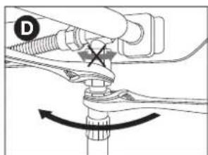
text_image
Technical diagram showing mechanical assembly with labeled component D and rotation arrownatural_image
Technical line drawing of a mechanical assembly with a tool and ring component (no text or symbols)
natural_image
Technical line drawing of a mechanical component with no visible text or symbolsnatural_image
Technical line drawing of a mechanical device with no visible text or symbols
natural_image
Line drawing of a medical or laboratory setup with a device and tubing (no text or symbols)6.5 Substituir o cilindro
natural_image
Line drawing of a toothpaste brush with 'barbecook' branding on the head (no other text or symbols)natural_image
Technical line drawing of a mechanical component with a circular indicator and a scale bar (no text or symbols)
natural_image
Simple line drawing of a mechanical component or tool with no visible text, numbers, or symbols.natural_image
Line drawing of a gas cylinder with inlet/outlet ports and two arrows indicating flow direction (no text or symbols)
text_image
barbecue B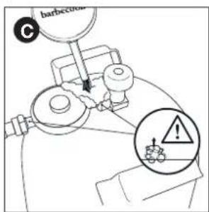
text_image
barbecue C
text_image
D ! barbecownatural_image
Diagram of a mechanical component with a shaft and housing, showing a directional arrow (no text or symbols)
natural_image
Simple line drawing of a lever with two circular ends and a central rod (no text or symbols)natural_image
Technical line drawing of a mechanical component with internal compartments and a directional arrow indicating motion (no text or symbols)9.6 Verificar as chamas
natural_image
Four identical rectangular metal grates with internal parallel grooves and small circular cutouts, arranged side by side (no text or symbols)natural_image
Diagram of a bottle with spiderweb and insect silhouettes inside, no text or symbols presentnatural_image
Technical line drawing of a mechanical assembly with a wrench and nut, no text or symbols present
natural_image
Technical line drawing of a mechanical component with directional arrows indicating motion (no text or symbols)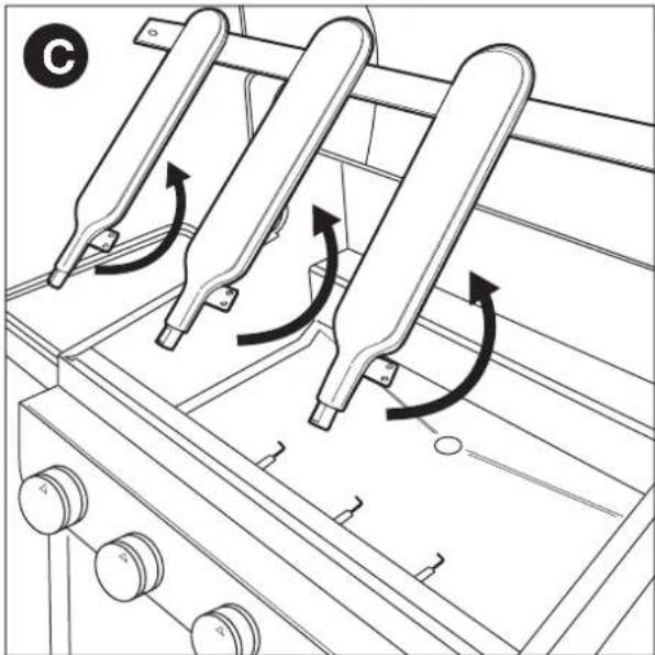
natural_image
Technical line drawing of a mechanical assembly with three curved components and rotational arrows indicating motion (no text or symbols)natural_image
Technical line drawing of a medical device with two views: top shows a tool inserted into a tube, bottom shows a mechanical component with a handle (no text or symbols)natural_image
Technical line drawing of a mechanical component with three top views and a downward arrow indicating process (no text or symbols)4.3 Emalj
natural_image
Diagram of a mechanical assembly with a threaded bolt and connector (no text or symbols)
natural_image
Mechanical diagram showing a screw being inserted into a pipe with a curved arrow indicating rotation (no text or symbols)natural_image
Mechanical diagram showing a pipe fitting with a threaded connector and an upward arrow indicating motion (no text or symbols)
text_image
Technical diagram showing pipe connection with labeled components D and G6.3.2 K OPPLING B
natural_image
Mechanical diagram showing a hand holding a screw and nut with a curved arrow indicating rotation (no text or symbols)natural_image
Mechanical diagram showing a valve assembly with a threaded connector and directional arrow (no text or labels)
natural_image
Mechanical diagram showing a lever mechanism with a star symbol and curved arrow indicating rotation (no text or labels)natural_image
Technical line drawing of a mechanical measurement setup with a tool and ring (no text or symbols)
natural_image
Technical line drawing of a mechanical assembly with no visible text or symbolsnatural_image
Technical line drawing of a mechanical device with no visible text or symbols
natural_image
Line drawing of a mechanical device with a circular component and a rectangular housing (no text or symbols)natural_image
Line drawing of a toothpaste brush with 'barbecook' branding on the head (no other text or symbols)natural_image
Line drawing of a mechanical joint or pipe fitting with a circular gauge and checkmark (no text or symbols)
natural_image
Simple line drawing of a hand holding a tool or device, with no text or symbols present.natural_image
Line drawing of a gas cylinder with internal components and directional arrows (no text or symbols)
text_image
barbecook B
text_image
barbecue C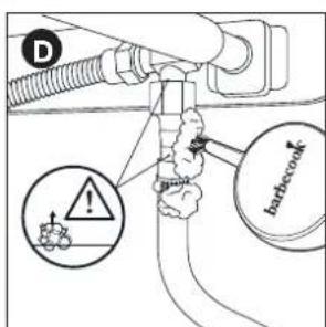
text_image
D hardcock
natural_image
Diagram of a mechanical component with a shaft and housing, showing a directional arrow (no text or symbols)
natural_image
Simple line drawing of a lever with two circular ends and a central pivot point (no text or symbols)natural_image
Technical line drawing of a mechanical component with internal compartments and a black arrow indicating a specific section (no text or symbols present)natural_image
Three identical wire mesh panels arranged horizontally, each with a central slot and two small circular cutouts (no text or symbols)natural_image
Diagram of a bottle with spiderweb pattern inside, showing internal structure (no text or symbols)
natural_image
Technical diagram of a car interior showing a lever mechanism with wrench and screwdriver (no text or symbols)
natural_image
Technical line drawing of a mechanical component with directional arrows indicating motion (no text or symbols)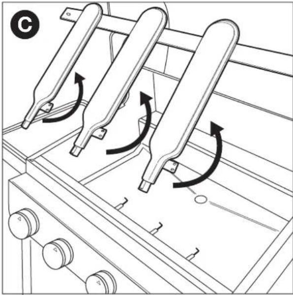
natural_image
Technical line drawing of a mechanical device with three curved components and rotational arrows indicating motion (no text or symbols)text_image
QR code image with a central logo, likely linking to a digital resource or website.GO TO WWW.BARBECOOK.COM, REGISTER YOUR BARBECOOK AND YOUR BARBECOOK EXPERIENCE WILL BE FURTHER IMPROVED!
THIS IS YOUR UNIQUE SERIAL N°
DA - BRUGERVEJLEDNING
1 Registrering af din enhed....138
3 V I G T I G E SIKKERHEDSANVISNINGER
natural_image
Technical line drawing of a medical device with two views: top shows a cylindrical device with internal structure, bottom shows a circular device with a handle and connector (no text or symbols)natural_image
Technical line drawing of a mechanical component with three top views and a downward arrow indicating assembly or disassembly (no text or symbols present)4.3 Emalje
| Land Sammenkobling | |
| BE, CH, CZ, DK, ES, FI, GB, IE, IT, PT, SI Sammenkobling | A |
| FR Sammenkobling | B |

natural_image
Diagram of a mechanical assembly with a threaded bolt and connector (no text or symbols)
natural_image
Mechanical diagram showing a screw being inserted into a housing with an arrow indicating rotation (no text or symbols)natural_image
Mechanical diagram showing a pipe fitting with a valve and directional arrow (no text or symbols)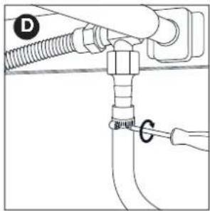
text_image
D G6.3.2 S AMMENKOBLING B
natural_image
Diagram of a mechanical assembly with a threaded pipe and valve, showing an upward force arrow (no text or symbols present)
natural_image
Mechanical diagram showing a lever mechanism with a curved arrow indicating rotational motion (no text or symbols present)natural_image
Mechanical diagram showing a connector with threaded tube and valve, no text or symbols present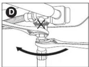
natural_image
Mechanical diagram showing a lever mechanism with a star symbol and curved arrow indicating rotation (no text or labels)natural_image
Diagram of a mechanical assembly with a tool and rotating component (no text or symbols)
natural_image
Technical line drawing of a mechanical assembly with no visible text or symbolsnatural_image
Technical line drawing of a mechanical assembly with no visible text or symbols
natural_image
Line drawing of a medical or laboratory setup with a device and tubing (no text or symbols)natural_image
Line drawing of a toothbrush with 'barbecook' branding on the head (no other text or symbols)natural_image
Line drawing of a mechanical joint or pipe fitting with a circular gauge (no text or symbols)
natural_image
Simple line drawing of a hand holding a tool with a cross mark, no text or symbols presentnatural_image
Line drawing of a gas cylinder with inlet/outlet ports and two arrows indicating flow direction (no text or symbols)
text_image
B barbcock
text_image
barbecue C
text_image
D barbecowDin trykregulator og sammenkobling kan afvige fra de viste i illustrationen.
natural_image
Diagram of a mechanical component with a shaft and threaded end, showing a directional arrow (no text or symbols)natural_image
Simple line drawing of a lever with two circular ends and a central pivot point (no text or symbols)natural_image
Technical line drawing of a vehicle battery pack with an arrow indicating a component (no text or symbols present)natural_image
Three identical wire mesh panels arranged horizontally, each with vertical slats and small circular cutouts (no text or symbols)natural_image
Diagram of a bottle with spiderweb pattern inside, showing internal structure (no text or symbols)
natural_image
Technical diagram of a mechanical assembly with a wrench and screwdriver inserted into a component (no text or symbols)
natural_image
Technical line drawing of a mechanical component with directional arrows indicating motion (no text or symbols)
natural_image
Technical line drawing of a mechanical assembly with three curved components and directional arrows indicating motion (no text or symbols)natural_image
Technical line drawing of a medical device with two views: top shows a cylindrical device with attached cable, bottom shows a circular device with a handle and connector (no text or symbols)natural_image
Technical line drawing of a mechanical component with three top views and a downward arrow indicating process (no text or symbols)4.3 Emali
natural_image
Diagram of a mechanical assembly with a threaded component and an upward arrow indicating motion (no text or symbols)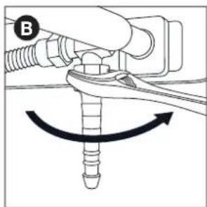
natural_image
Mechanical diagram showing a screw being inserted into a connector with a curved arrow indicating rotation (no text or symbols)natural_image
Mechanical diagram showing a pipe fitting with a threaded connector and an upward arrow indicating motion (no text or symbols)
text_image
Technical diagram showing pipe connection with labeled components D and G6.3.2 L IITIN B
natural_image
Mechanical diagram showing a hand adjusting a bolt with a curved arrow indicating rotational motion (no text or symbols)natural_image
Mechanical diagram showing a valve assembly with a threaded connector and directional arrow (no text or symbols)
natural_image
Mechanical diagram showing a lever mechanism with a star symbol and curved arrow indicating rotation (no text or labels)natural_image
Technical line drawing of a mechanical assembly with a tool and ring (no text or symbols)
natural_image
Technical line drawing of a mechanical assembly with no visible text or symbolsnatural_image
Technical line drawing of a mechanical component with no visible text or symbols
natural_image
Line drawing of a medical or laboratory setup with a device and tubing (no text or symbols)6.5 Säiliön vaihto
natural_image
Line drawing of a toothpaste brush with 'barbecook' label on the head (no other text or symbols)natural_image
Line drawing of a mechanical component with a circular mark and checkmark, no text or symbols present
natural_image
Simple line drawing of a hand holding a tool with a cross mark and a plus symbol (no text or labels)natural_image
Line drawing of a gas cylinder with labeled arrows (no text or symbols on the diagram itself)
text_image
barbecueck B
text_image
barbecue C
text_image
D barbecook
natural_image
Diagram of a mechanical component with a shaft and housing, showing a directional arrow (no text or symbols)
natural_image
Simple line drawing of a lever with two circular ends and a central pivot point (no text or symbols)natural_image
Line drawing of a vehicle battery pack with an arrow indicating the direction of cooling (no text or symbols present)natural_image
Three identical wire mesh panels arranged horizontally, each with a central slot and two small circular cutouts (no text or symbols)natural_image
Diagram of a bottle with spiderweb pattern inside, showing internal structure (no text or symbols)natural_image
Technical diagram of a mechanical assembly with a wrench and screwdriver inserted into a component (no text or symbols)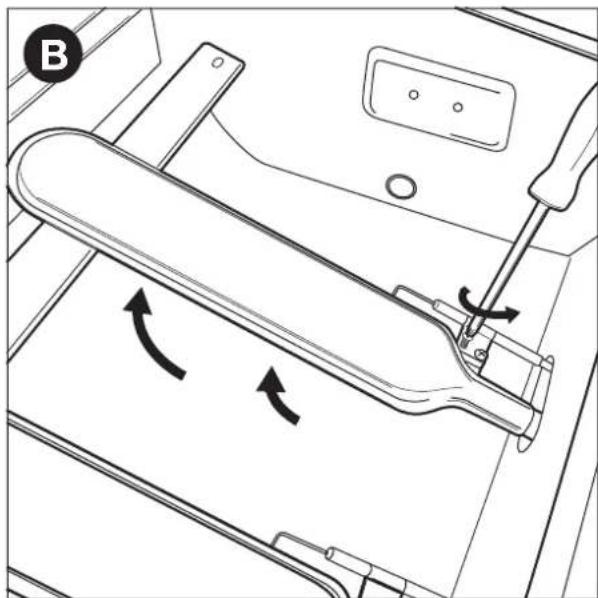
natural_image
Technical line drawing of a mechanical assembly with directional arrows indicating motion (no text or symbols)
natural_image
Technical line drawing of a mechanical assembly with three curved components and rotational arrows indicating motion (no text or symbols)natural_image
Technical line drawing of a medical device with two views: top shows a cylindrical device with cable, bottom shows a circular device with a ring and attached tubing (no text or symbols)natural_image
Technical line drawing of a mechanical component with three top views and a downward arrow indicating assembly or disassembly (no text or symbols present)4.3 Emalje
6 TILKOBLING AV GASS TIL APPARATET
6.1 Hvilken flaske, slange, regulator
natural_image
Diagram of a mechanical assembly with a threaded component and an upward arrow, no text or symbols present.
natural_image
Mechanical diagram showing a screw being inserted into a plug, with an arrow indicating rotational motion (no text or symbols)natural_image
Mechanical diagram showing a pipe fitting with a threaded connector and an upward arrow indicating motion (no text or symbols)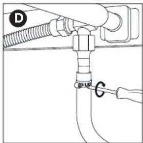
text_image
Technical diagram showing pipe connection with labeled components D and G6.3.2 K OBLING B
natural_image
Mechanical diagram showing a hand holding a screw and nut with a curved arrow indicating rotation (no text or symbols)2 Skru gasslangen på koblingen (C) og skru den fast med to fastnøkler. Hold koblingen med en 22 mm fastnøkkel, mens du dreier slangen med en skiftenøkkel (D).

natural_image
Mechanical diagram showing a pipe fitting with a valve and directional arrow (no text or symbols)
natural_image
Mechanical diagram showing a lever mechanism with a star symbol and curved arrow indicating rotation (no text or labels)natural_image
Technical line drawing of a mechanical measurement setup with a tool and ring (no text or symbols)
natural_image
Technical line drawing of a mechanical assembly with no visible text or symbolsnatural_image
Technical line drawing of a mechanical device with no visible text or symbols
natural_image
Line drawing of a mechanical device with a circular component and a rectangular housing (no text or symbols)6.5 Skifte flasken
7 SJEKKING FOR GASSLEKKASJE
natural_image
Line drawing of a toothpaste brush with 'barbecook' label on the head (no other text or symbols)natural_image
Line drawing of a mechanical component with a circular mark and checkmark, no text or symbols present
natural_image
Simple line drawing of a hand holding a tool with a cross mark and a droplet, no text or symbols present.natural_image
Line drawing of a gas cylinder with directional arrows indicating flow or movement (no text or symbols)
text_image
B barbecook
text_image
barbecue C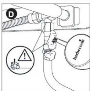
text_image
D barbecocknatural_image
Diagram of a mechanical component with a shaft and housing, showing a directional arrow (no text or symbols)natural_image
Simple line drawing of a lever with two circular ends and a central pivot point (no text or symbols)natural_image
Technical line drawing of a vehicle battery pack with internal compartments and a black arrow indicating a component (no text or symbols)natural_image
Three identical wire mesh panels arranged horizontally, each with a central hole and a curved cutout (no text or symbols)11 VEDLIKEHOLD AV APPARATET
natural_image
Diagram of a bottle with internal spiderweb structure and two insect-like insects (no text or labels)
natural_image
Diagram of a car interior showing a lever mechanism with a wrench and screwdriver (no text or symbols)
natural_image
Technical line drawing of a mechanical assembly with directional arrows indicating motion (no text or symbols)
natural_image
Technical line drawing of a mechanical assembly with three curved components and rotational arrows indicating motion (no text or symbols)natural_image
Technical line drawing of a mechanical device with two views: top shows a cylindrical component being inserted, bottom shows a circular component with a handle and mounting bracket (no text or symbols)natural_image
Technical line drawing of a mechanical component with three top views and a downward arrow indicating assembly or disassembly (no text or symbols present)4.3 Zománc
natural_image
Mechanical diagram showing a threaded connector with an upward arrow indicating motion (no text or symbols)
natural_image
Mechanical diagram showing a screw being inserted into a pipe with a curved arrow indicating rotation (no text or symbols)natural_image
Technical diagram of a mechanical assembly with threaded pipe and valve (no text or symbols)
text_image
D G6.3.2 B CSATLAKOZÓ
natural_image
Mechanical diagram showing a hand connecting a spring and nut to a bracket with an arrow indicating rotational motion (no text or symbols)natural_image
Mechanical diagram showing a pipe fitting with a valve and directional arrow (no text or symbols)
text_image
Diagram showing mechanical assembly with labeled component D and directional arrow indicating rotation or movementnatural_image
Diagram of a mechanical measurement setup with a tool and rotating component (no text or symbols)
natural_image
Technical line drawing of a mechanical assembly with no visible text or symbolsnatural_image
Technical line drawing of a mechanical assembly with no visible text or symbols
natural_image
Line drawing of a mechanical device with a circular component and lever (no text or symbols)natural_image
Line drawing of a toothbrush with 'barbecook' branding on the lid (no additional text or symbols)natural_image
Line drawing of a mechanical joint or pipe assembly with a circular gauge and a curved handle (no text or symbols)
natural_image
Simple line drawing of a hand holding a tool, no text or symbols presentnatural_image
Line drawing of a gas cylinder with inlet/outlet ports and directional arrows indicating flow (no text or symbols)
text_image
barbecook B
text_image
barbecue C
text_image
D barbecownatural_image
Diagram of a mechanical component with a tool inserted into a housing, showing a shaft and housing (no text or symbols)
natural_image
Simple line drawing of a lever with two circular ends and a central dot (no text or symbols)natural_image
Technical line drawing of a mechanical component with internal compartments and a directional arrow indicating motion (no text or symbols)natural_image
Three identical wire mesh panels arranged horizontally, each with a central hole and a small circular cutout (no text or symbols)natural_image
Diagram of a cylindrical container with internal spiderweb structure and two small insects inside (no text or labels)
natural_image
Technical diagram of a mechanical assembly with a wrench and screwdriver inserted into a component (no text or symbols)
natural_image
Technical line drawing of a mechanical component with directional arrows indicating motion (no text or symbols)
natural_image
Technical line drawing of a mechanical assembly with three curved components and directional arrows indicating motion (no text or symbols)natural_image
Technical line drawing of a medical device with two views: top shows a flexible tube, bottom shows a circular component with a handle (no text or symbols)natural_image
Technical line drawing of a mechanical component with three top views and a downward arrow indicating assembly or disassembly (no text or symbols present)4.3 Email
natural_image
Mechanical diagram showing a threaded fastener inserted into a pipe with an upward arrow indicating force (no text or symbols present)
natural_image
Mechanical diagram showing a screw being inserted into a housing with a curved arrow indicating rotation (no text or symbols)natural_image
Technical diagram of a mechanical assembly with threaded pipe and valve (no text or symbols)
natural_image
Pure diagram of a pipe fitting with labeled parts (D and C), no text or symbols present6.3.2 C UPLAJUL B
natural_image
Diagram of a mechanical assembly with a hand holding a bolt and a curved arrow indicating rotation (no text or symbols)natural_image
Mechanical diagram showing a valve assembly with a threaded connector and a directional arrow (no text or symbols)
natural_image
Diagram of a mechanical assembly with a star-shaped component and curved arrows indicating motion (no text or symbols)natural_image
Diagram of a mechanical measurement setup with a tool and rotating component (no text or symbols)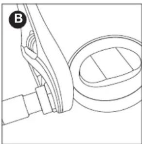
natural_image
Technical line drawing of a mechanical assembly with no visible text or symbolsnatural_image
Technical line drawing of a mechanical assembly with no visible text or symbols
natural_image
Line drawing of a medical device with a central device and surrounding components (no text or symbols)natural_image
Line drawing of a toothpaste brush with 'barbecook' branding on the head (no additional text or symbols)natural_image
Pure mechanical diagram showing a lever mechanism with a circular indicator (no text or symbols)
natural_image
Diagram of a mechanical joint or connector with a cross symbol and a plus sign, no readable text or labels present.natural_image
Line drawing of a gas cylinder with inlet/outlet ports and two arrows indicating flow direction (no text or symbols)
text_image
barbcock B
text_image
barbecue C
text_image
D badcoaknatural_image
Diagram of a mechanical component with a shaft and housing, showing a directional arrow (no text or symbols)natural_image
Simple line drawing of a lever with two circular ends and a central pivot point (no text or symbols)natural_image
Technical line drawing of a mechanical component with internal compartments and a directional arrow indicating motion (no text or symbols)natural_image
Three identical wire mesh grating panels arranged horizontally (no text or symbols)natural_image
Diagram of a bottle with spiderweb and butterfly, no text or symbols present
natural_image
Technical line drawing of a mechanical assembly with a wrench and screwdriver (no text or symbols)
natural_image
Technical line drawing of a mechanical component with directional arrows indicating motion (no text or symbols)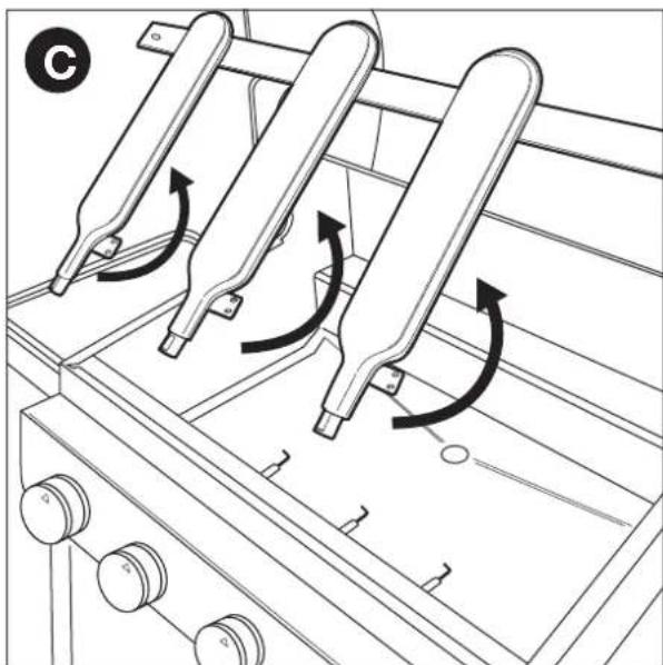
natural_image
Technical line drawing of a mechanical assembly with three curved components and rotational arrows indicating motion (no text or symbols)natural_image
Technical line drawing of a mechanical device with two views: top shows a cylindrical component being inserted, bottom shows a circular component with a handle and mounting bracket (no text or symbols)natural_image
Technical line drawing of a mechanical component with three top views and a downward arrow indicating process (no text or symbols)4.3 Smalt
natural_image
Mechanical diagram showing a threaded component inserted into a pipe with an upward arrow indicating motion (no text or symbols)
natural_image
Mechanical diagram showing a screw being inserted into a pipe with a curved arrow indicating rotation (no text or symbols)natural_image
Technical diagram of a mechanical assembly with a threaded component and an upward arrow indicator (no text or symbols present)
text_image
D G6.3.2 S POJKA B
natural_image
Mechanical diagram showing a hand connecting a spring and nut to a bracket with an arrow indicating rotational motion (no text or symbols)natural_image
Mechanical diagram showing a pipe fitting with a valve and directional arrow (no text or symbols)
text_image
Diagram showing mechanical assembly with labeled component D and directional arrow indicating rotation or movementnatural_image
Technical line drawing of a mechanical assembly with a tool and ring (no text or symbols)
natural_image
Technical line drawing of a mechanical assembly with no visible text or symbolsnatural_image
Technical line drawing of a mechanical device with no visible text or symbols
natural_image
Line drawing of a medical or laboratory setup with a device and tubing (no text or symbols)natural_image
Line drawing of a toothpaste brush with 'barbecook' branding on the head (no other text or symbols)natural_image
Pure mechanical diagram showing a lever mechanism with no text or symbols
natural_image
Diagram of a mechanical or biological structure with no visible text, numbers, or symbolsnatural_image
Line drawing of a gas cylinder with inlet/outlet ports and two arrows indicating flow direction (no text or symbols)
text_image
B barbcock
text_image
barbecue C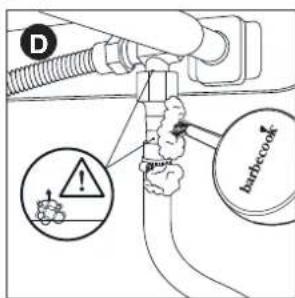
text_image
D barbecownatural_image
Diagram of a mechanical component with a tool inserted into a housing, showing a force direction (no text or symbols)natural_image
Simple line drawing of a lever with two circular ends and a central pivot point (no text or symbols)natural_image
Technical line drawing of a mechanical component with internal compartments and a directional arrow indicating motion (no text or symbols)natural_image
Three identical wire mesh panels arranged horizontally, each with a central slot and two small circular cutouts (no text or symbols)natural_image
Diagram of a bottle with spiderweb structure and two butterflies inside (no text or labels)
natural_image
Technical diagram of a mechanical assembly with a wrench and screwdriver inserted into a component (no text or symbols)
natural_image
Technical line drawing of a mechanical component with directional arrows indicating motion (no text or symbols)
natural_image
Technical line drawing of a mechanical assembly with three curved components and rotational arrows indicating motion (no text or symbols)natural_image
Technical line drawing of a medical device with two views: top shows a tool inserted into a tube, bottom shows a mechanical component with a handle (no text or symbols)natural_image
Technical line drawing of a mechanical component with three top views and a base view (no text or symbols)4.3 Εμαγιέ
natural_image
Diagram of a mechanical assembly with a threaded connector and an upward arrow indicating motion (no text or symbols)
natural_image
Mechanical diagram showing a screw being inserted into a housing with a curved arrow indicating rotation (no text or symbols)natural_image
Mechanical diagram showing a bolt and pipe assembly with an upward arrow indicating motion (no text or symbols)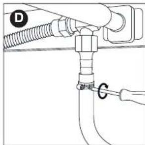
text_image
D C6.3.2 Σ YZEYEH B
natural_image
Mechanical diagram showing a hand holding a bolt with a curved arrow indicating rotational motion (no text or symbols)natural_image
Mechanical assembly diagram showing a valve and fitting with an upward arrow indicating motion (no text or symbols)
natural_image
Mechanical diagram showing a lever mechanism with a valve and rotating component (no text or symbols)natural_image
Technical line drawing of a mechanical assembly with a tool and ring (no text or symbols)
natural_image
Technical line drawing of a mechanical assembly with no visible text or symbolsnatural_image
Technical line drawing of a mechanical device with no visible text or symbols
natural_image
Line drawing of a mechanical device with a circular component and a rectangular housing (no text or symbols)natural_image
Line drawing of a toothpaste brush with 'barbecook' branding on the head (no additional text or symbols)natural_image
Pure technical diagram of a pipe fitting with a checkmark indicating a detail (no text or symbols)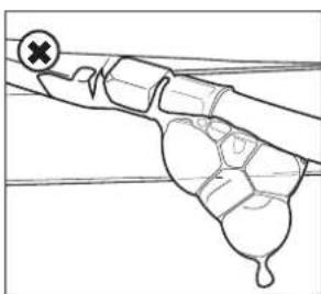
natural_image
Diagram of a hand holding a tool with a cross mark and a plus symbol (no text or labels)natural_image
Line drawing of a gas cylinder with inlet/outlet ports and two arrows indicating flow direction (no text or symbols)
text_image
barbecock B
text_image
barbecue C
text_image
D barbecownatural_image
Technical line drawing of a mechanical component with a lever and shaft, showing no text or symbols
9 'ANAMMA TΩN KΛΙΒ'ΑΝΩΝ

natural_image
Simple line drawing of a lever with two circular ends and a central pivot point (no text or symbols)natural_image
Technical line drawing of a vehicle battery pack with internal compartments and a black arrow indicating a component (no text or symbols present)natural_image
Three identical wire mesh grating panels arranged horizontally (no text or symbols)natural_image
Diagram of a bottle with spiderweb and insect, no text or symbols present
natural_image
Technical diagram of a mechanical assembly with a wrench and screwdriver inserted into a component (no text or symbols)
natural_image
Technical line drawing of a mechanical component with directional arrows indicating motion (no text or symbols)
natural_image
Technical line drawing of a mechanical assembly with three curved components and rotational arrows indicating motion (no text or symbols)3 DÔLEŽITÉ BEZPEČNOSTNÉ POKYNY
3.1 Prečítajte si a dodržiavajte pokyny
natural_image
Technical line drawing of a medical device with two views: top shows a cylindrical device with attached cable, bottom shows a circular device with a handle and connector (no text or symbols)natural_image
Technical line drawing of a mechanical component with three top views and a downward arrow indicating assembly or disassembly (no text or symbols present)4.3 Smalt
natural_image
Mechanical diagram showing a threaded fastener inserted into a pipe with an upward arrow indicating force (no text or symbols present)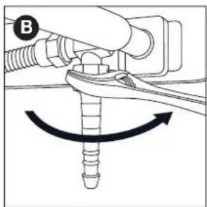
natural_image
Mechanical diagram showing a screw being inserted into a housing with a curved arrow indicating rotation (no text or symbols)2 Nasuňte hadicu na spojku (C) a dotiahnite eskapásku pomocou krížového skrutkovača (D).

natural_image
Diagram of a mechanical assembly with a threaded pipe and directional arrow (no text or labels)
natural_image
Pure diagram of a pipe fitting with labeled components (no text or symbols)6.3.2 S POJKA TYPU B
natural_image
Diagram of a hand holding a screw and nut with a curved arrow indicating rotation (no text or symbols)natural_image
Diagram of a mechanical or fluidic component with a valve and fitting, showing no text or symbols.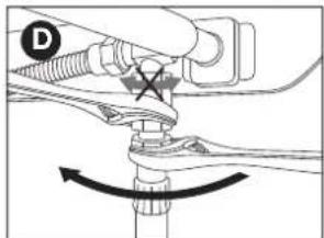
natural_image
Mechanical diagram showing a lever mechanism with a star symbol and curved arrow indicating rotation (no text or labels)6.4 Pripojenie hadice a flaše k regulátoru
natural_image
Technical line drawing of a mechanical assembly with a tool and curved component (no text or symbols)
natural_image
Technical line drawing of a mechanical assembly with no visible text or symbolsnatural_image
Technical line drawing of a mechanical device with no visible text or symbols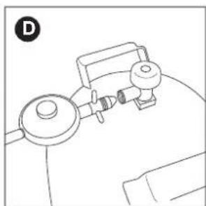
natural_image
Line drawing of a mechanical device with no visible text or symbols6.5 Výmena fláše
natural_image
Line drawing of a toothbrush with 'barbecook' text on the lid (no other text or symbols)7.5 Kontrola úniku plynu
natural_image
Pure mechanical diagram showing a pipe fitting with a checkmark indicating a detail (no text or symbols)
natural_image
Diagram of a mechanical joint or connector with a cross symbol and a plus sign, no readable text or labels present.natural_image
Line drawing of a gas cylinder with inlet/outlet ports and two arrows indicating flow direction (no text or symbols)
text_image
barbcock B
text_image
barbecue C
text_image
D badbecownatural_image
Diagram of a mechanical component with a shaft and housing, showing a directional arrow (no text or symbols)9.2.1 P OMOCOU ZAPAL'OVAČA
natural_image
Simple line drawing of a lever with two circular ends and a central pivot point (no text or symbols)natural_image
Technical line drawing of a mechanical component with internal compartments and a directional arrow indicating motion (no text or symbols)natural_image
Three identical wire mesh panels arranged horizontally, each with a central hole and no text or symbols.natural_image
Diagram of a cylindrical container with spiderweb pattern and two small insects inside (no text or symbols)
natural_image
Diagram of a car interior showing a lever mechanism with a wrench and screwdriver (no text or symbols)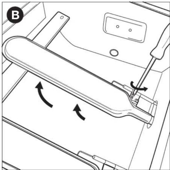
natural_image
Technical line drawing of a mechanical component with directional arrows indicating motion (no text or symbols)
natural_image
Technical line drawing of a mechanical assembly with three curved components and rotational arrows indicating motion (no text or symbols)3 Olulised ohutusjuhised....266
3 OLULISED OHUTUSJUHISED
natural_image
Technical line drawing of a medical device with two views: top shows a cylindrical device with internal structure, bottom shows a circular device with a handle and connector (no text or symbols)natural_image
Technical line drawing of a mechanical component with three top views and a downward arrow indicating assembly or disassembly (no text or symbols present)4.3 Email
natural_image
Mechanical diagram showing a threaded fastener inserted into a pipe with an upward arrow indicating force (no text or symbols present)
natural_image
Mechanical diagram showing a screw being inserted into a housing with a curved arrow indicating rotation (no text or symbols)natural_image
Technical diagram of a mechanical assembly with threaded pipe and valve (no text or symbols)
natural_image
Pure diagram of a pipe fitting with labeled parts (D and C), no text or symbols present.6.3.2 M UHV B
natural_image
Mechanical diagram showing a hand holding a bolt with a curved arrow indicating rotational motion (no text or symbols)natural_image
Diagram of a mechanical valve assembly with a threaded connector and directional arrow (no text or labels)
natural_image
Mechanical diagram showing a lever mechanism with a star-shaped component and curved arrows indicating motion (no text or symbols)natural_image
Technical line drawing of a mechanical assembly with a tool and ring component (no text or symbols)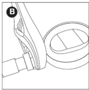
natural_image
Technical line drawing of a mechanical component with a curved bracket and circular housing (no text or symbols)natural_image
Technical line drawing of a mechanical assembly with no visible text or symbols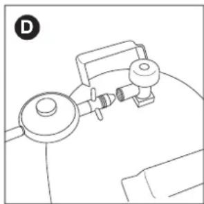
natural_image
Line drawing of a medical or laboratory setup with a device and tubing (no text or symbols)6.5 Ballooni asendamine
natural_image
Line drawing of a toothpaste brush with 'barbecook' branding on the head (no additional text or symbols)7.5 Gaasilekete kontrollimiseks
natural_image
Technical line drawing of a mechanical component with a circular indicator and crosshair (no text or symbols)
natural_image
Diagram of a hand holding a tool with a cross symbol, no text or labels presentnatural_image
Line drawing of a gas cylinder with inlet/outlet ports and two arrows indicating flow direction (no text or symbols)
text_image
barbcock
text_image
barbecue C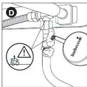
text_image
D barbecuenatural_image
Diagram of a mechanical component with a tool inserted into a shaft, showing motion direction (no text or symbols)text_image
QR code image containing encoded data, with a central logo or watermarkGO TO WWW.BARBECOOK.COM, REGISTER YOUR BARBECOOK AND YOUR BARBECOOK EXPERIENCE WILL BE FURTHER IMPROVED!
THIS IS YOUR UNIQUE SERIAL N°
natural_image
Simple line drawing of a mechanical lever with two circular ends and a central pivot point (no text or symbols)natural_image
Technical line drawing of a mechanical component with internal compartments and a directional arrow indicating motion (no text or symbols)natural_image
Three identical wire mesh panels arranged horizontally, each with a central square cutout and two small circular holes (no text or symbols)natural_image
Diagram of a cylindrical container with spiderweb and insect silhouettes inside, no text or symbols present
natural_image
Technical line drawing of a mechanical assembly with a wrench and screwdriver (no text or symbols)
natural_image
Technical diagram of a mechanical assembly with directional arrows indicating motion (no text or symbols)
natural_image
Technical line drawing of a mechanical assembly with three curved components and directional arrows indicating motion (no text or symbols)natural_image
Technical line drawing of a medical device with two views: top shows a curved tube with cable, bottom shows a circular component with a handle and connector (no text or symbols)natural_image
Technical line drawing of a mechanical component with three top views and a downward arrow indicating assembly or disassembly (no text or symbols present)4.3 Emalis
natural_image
Diagram of a mechanical assembly with a threaded component and an upward arrow indicating motion (no text or symbols)
natural_image
Mechanical diagram showing a screw being inserted into a plug, with an arrow indicating rotational motion (no text or symbols)natural_image
Mechanical diagram showing a pipe fitting with a threaded connector and an upward arrow indicating motion (no text or symbols)
text_image
Technical diagram showing pipe connection with labeled components D and G6.3.2 B MOVA
natural_image
Mechanical diagram showing a lever mechanism with a curved arrow indicating rotational motion (no text or symbols present)natural_image
Mechanical diagram showing a pipe fitting with a valve and directional arrow (no text or symbols)
natural_image
Mechanical diagram showing a lever mechanism with rotating components and a star symbol (no text or labels)natural_image
Technical line drawing of a mechanical measuring tool interacting with a cylindrical component (no text or symbols)
natural_image
Technical line drawing of a mechanical assembly with no visible text or symbolsnatural_image
Technical line drawing of a mechanical device with no visible text or symbols
natural_image
Line drawing of a medical or laboratory setup with a device and tubing (no text or symbols)6.5 Baliono keitimas
natural_image
Line drawing of a decorative lamp with 'barbecook' branding on the body (no other text or symbols)7.5 Norint patikrinti, ar néra duju nuotëkio
natural_image
Simple line drawing of a hand holding a tool with a cross mark, no text or symbols presentnatural_image
Line drawing of a gas cylinder with inlet/outlet ports and two arrows indicating flow direction (no text or symbols)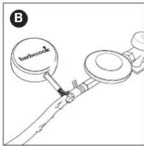
text_image
barbcock B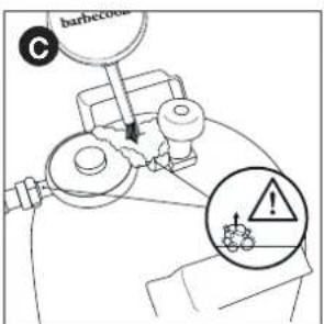
text_image
barbecue C
text_image
D badbecownatural_image
Diagram of a mechanical component with a tool inserted into a housing, showing a force direction (no text or symbols)natural_image
Simple line drawing of a lever with two circular ends and a central pivot point (no text or symbols)natural_image
Technical line drawing of a mechanical component with internal compartments and a directional arrow indicating motion (no text or symbols)natural_image
Three identical wire mesh grating panels arranged horizontally (no text or symbols)natural_image
Diagram of a cylindrical container with internal wireframe structure and two small insects (no text or symbols)natural_image
Technical diagram showing a mechanical assembly with a wrench and screwdriver inserted into a component (no text or symbols present)
natural_image
Technical line drawing of a mechanical component with directional arrows indicating motion (no text or symbols)
natural_image
Technical line drawing of a mechanical assembly with three curved components and directional arrows indicating motion (no text or symbols)natural_image
Technical line drawing of a mechanical device with two views: top shows a cylindrical component being inserted, bottom shows a circular component with a handle and mounting bracket (no text or symbols)natural_image
Technical line drawing of a mechanical component with three top views and a base view (no text or symbols)4.3 Emalja
natural_image
Diagram of a mechanical assembly with a threaded component and an upward arrow indicating motion (no text or symbols)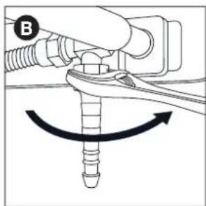
natural_image
Mechanical diagram showing a screw being inserted into a plug, with an arrow indicating rotational motion (no text or symbols)natural_image
Mechanical diagram showing a pipe fitting with a threaded connector and an upward arrow indicating motion (no text or symbols)
text_image
Technical diagram showing pipe connection with labeled components D and G6.3.2 B SAVIENOJUMS
Nepieciešama 22 mm uzgriežnatslega un bīdatslega.
natural_image
Mechanical diagram showing a lever mechanism with a curved arrow indicating rotational motion (no text or symbols present)natural_image
Mechanical diagram showing a pipe fitting with a valve and directional arrow (no text or symbols)
natural_image
Mechanical diagram showing a lever mechanism with rotating components and a star symbol (no text or labels)6.4 Šlūtenes un balona pievienošana regulatoram
natural_image
Technical line drawing of a mechanical measuring tool interacting with a cylindrical component (no text or symbols)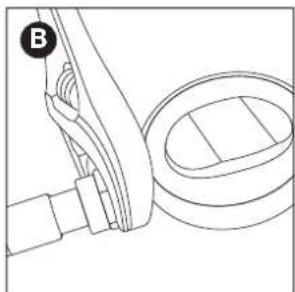
natural_image
Technical line drawing of a mechanical assembly with no visible text or symbolsnatural_image
Technical line drawing of a mechanical device with no visible text or symbols
natural_image
Line drawing of a medical or laboratory setup with a device and tubing (no text or symbols)natural_image
Line drawing of a decorative lamp with 'barbecook' branding on the body (no other text or symbols)natural_image
Simple line drawing of a hand holding a tool with a cross mark, no text or symbols presentnatural_image
Line drawing of a gas cylinder with inlet/outlet ports and two arrows indicating flow direction (no text or symbols)
text_image
barbcock B
text_image
barbecue C
text_image
D badcooknatural_image
Diagram of a mechanical component with a shaft and threaded end, showing a directional arrow (no text or symbols)natural_image
Simple line drawing of a lever with two circular ends and a central rod (no text or symbols)natural_image
Technical line drawing of a mechanical component with internal compartments and a directional arrow indicating motion (no text or symbols)natural_image
Three identical wire mesh panels arranged horizontally, each with a central slot and two small circular cutouts (no text or symbols)natural_image
Diagram of a cylindrical container with spiderweb and spider inside, no text or symbols presentnatural_image
Technical diagram of a mechanical assembly with a wrench and screwdriver inserted into a component (no text or symbols)
natural_image
Technical line drawing of a mechanical component with directional arrows indicating motion (no text or symbols)
natural_image
Technical line drawing of a mechanical assembly with three curved components and rotational arrows indicating motion (no text or symbols)natural_image
Technical line drawing of a medical device with two views: top shows a cylindrical device with attached cable, bottom shows a circular device with a handle and connector (no text or symbols)natural_image
Technical line drawing of a mechanical component with three top views and a base view (no text or symbols)4.3 Emalia
natural_image
Mechanical assembly diagram showing a threaded connector with an upward arrow indicating motion (no text or symbols)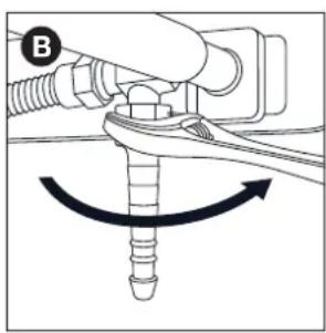
natural_image
Mechanical diagram showing a screw being inserted into a housing with an arrow indicating rotational motion (no text or symbols)natural_image
Technical diagram of a mechanical assembly with a threaded pipe and valve, showing an upward force arrow (no text or symbols present)
text_image
D C6.3.2 Z ŁACZKA B
natural_image
Diagram of a mechanical assembly with a threaded pipe and valve, showing an upward force arrow (no text or symbols present)
natural_image
Diagram of a mechanical assembly with a tool and rotating component (no text or symbols)natural_image
Mechanical assembly diagram showing a connector with threaded shaft and valve, no text or symbols present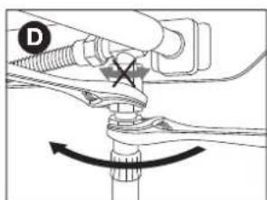
natural_image
Mechanical diagram showing a lever mechanism with rotating components and a star symbol (no text or labels)natural_image
Diagram of a mechanical measurement setup with a tool and rotating component (no text or symbols)
natural_image
Technical line drawing of a mechanical assembly with no visible text or symbolsnatural_image
Line drawing of a mechanical device with no visible text or symbols
natural_image
Line drawing of a mechanical device with a circular component and a rectangular housing (no text or symbols)6.5 Wymiana butli
natural_image
Line drawing of a toothpaste brush with 'barbecook' branding on the head (no additional text or symbols)text_image
Technical diagram showing a pipe fitting with a checkmark indicating a specific part, likely for installation or inspection.
natural_image
Diagram of a biological structure with a cross mark and arrow, no readable text or symbols presentnatural_image
Line drawing of a gas cylinder with inlet/outlet ports and two arrows indicating flow direction (no text or symbols)
text_image
barbecock B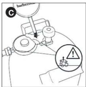
text_image
barbecue C
text_image
D barbecownatural_image
Diagram of a mechanical component with a shaft and housing, showing a directional arrow (no text or symbols)
natural_image
Simple line drawing of a lever with two circular ends and a central pivot point (no text or symbols)natural_image
Technical line drawing of a mechanical component with internal compartments and a black arrow indicating a directional change (no text or symbols)natural_image
Three identical wire mesh grating panels arranged horizontally (no text or symbols)natural_image
Diagram of a bottle with spiderweb pattern and insect silhouettes inside (no text or labels)natural_image
Technical diagram of a mechanical assembly with a wrench and screwdriver inserted into a component (no text or symbols)
natural_image
Technical line drawing of a mechanical component with directional arrows indicating motion (no text or symbols)
natural_image
Technical line drawing of a mechanical assembly with three curved components and directional arrows indicating motion (no text or symbols)natural_image
Technical line drawing of a medical device with two views: top shows a curved tool, bottom shows a cylindrical device with a handle (no text or symbols)natural_image
Technical line drawing of a mechanical component with three top views and a base view (no text or symbols)4.3 Емайл
natural_image
Diagram of a mechanical assembly with a threaded connector and an upward arrow indicating motion (no text or symbols)
natural_image
Mechanical diagram showing a screw being inserted into a housing with an arrow indicating rotational motion (no text or symbols)natural_image
Mechanical diagram showing a pipe fitting with a bolt and valve, no text or symbols present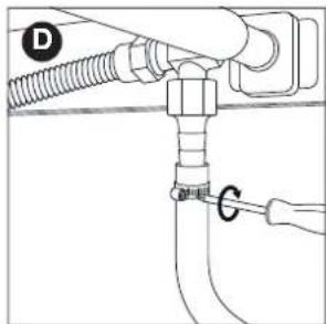
text_image
D C6.3.2 K уплунг В
natural_image
Mechanical diagram showing a lever mechanism with a curved arrow indicating rotational motion (no text or symbols present)natural_image
Mechanical assembly diagram showing a valve and fitting with an upward arrow indicating motion (no text or symbols)
natural_image
Mechanical diagram showing a lever mechanism with a star symbol and curved arrow indicating rotation (no text or labels)natural_image
Technical line drawing of a mechanical measurement setup with a tool and ring (no text or symbols)
natural_image
Technical line drawing of a mechanical assembly with no visible text or symbolsnatural_image
Technical line drawing of a mechanical assembly with no visible text or symbols
natural_image
Line drawing of a mechanical device with a circular component and lever (no text or symbols)natural_image
Line drawing of a bamboo-cook matchbox with a wooden stick (no text or symbols)natural_image
Line drawing of a pipe joint with a checkmark indicating a detail (no text or symbols present)
natural_image
Simple line drawing of a mechanical or biological structure with no visible text, numbers, or symbols.natural_image
Line drawing of a gas cylinder with two arrows indicating flow direction (no text or symbols)
text_image
barbecue B
text_image
barbecue C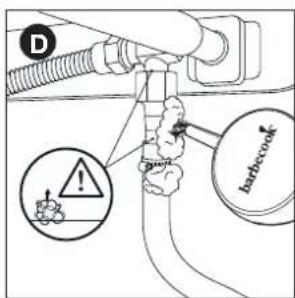
text_image
D ! barbecownatural_image
Diagram of a mechanical component with a shaft and housing, showing a directional arrow (no text or symbols)
natural_image
Simple line drawing of a mechanical lever or rod with two circular ends and a central shaft (no text or symbols)natural_image
Technical line drawing of a mechanical component with internal compartments and a directional arrow indicating motion (no text or symbols)natural_image
Three identical wire mesh panels arranged horizontally, each with a central hole and a small circular cutout (no text or symbols)natural_image
Diagram of a bottle with internal spiderweb structure and two insect-like insects (no text or labels)
natural_image
Technical diagram of a mechanical assembly with a wrench and screwdriver inserted into a component (no text or symbols)
natural_image
Technical line drawing of a mechanical component with directional arrows indicating motion (no text or symbols)
natural_image
Technical line drawing of a mechanical assembly with three curved components and directional arrows indicating motion (no text or symbols)natural_image
Technical line drawing of a mechanical device with two views: top shows a cylindrical component with a cable, bottom shows a circular component with a handle and mounting bracket (no text or symbols)natural_image
Technical line drawing of a mechanical component with three top views and a downward arrow indicating process (no text or symbols)4.3 Emajl
6.1 Katero jeklenko, cev in regulator?
natural_image
Diagram of a mechanical assembly with a threaded component and an upward arrow indicating motion (no text or symbols)
natural_image
Mechanical diagram showing a screw being inserted into a plug, with an arrow indicating rotational motion (no text or symbols)natural_image
Mechanical diagram showing a pipe fitting with a threaded connector and an upward arrow indicating motion (no text or symbols)
text_image
Technical diagram showing pipe connection with labeled components D and G6.3.2 S POJKA B
natural_image
Mechanical diagram showing a lever mechanism with a curved arrow indicating rotational motion (no text or symbols present)2 Plinsko cev privijte na spojko (C) in jo zategnite z dvema ključema. Spojko držite z 22 mm ključem in medtem cev privijajte s francozom (D).

natural_image
Mechanical diagram showing a pipe fitting with a valve and directional arrow (no text or symbols)
natural_image
Mechanical diagram showing a lever mechanism with rotating components and a star symbol (no text or labels)6.4 Priključitev cevi in jeklenke na regulator
natural_image
Diagram of a micrometer measuring a cylindrical object with a pointer (no text or symbols)
natural_image
Technical line drawing of a mechanical assembly with a tool and component (no text or symbols)natural_image
Technical line drawing of a mechanical device with no visible text or symbols
natural_image
Line drawing of a mechanical device with a circular component and a rectangular housing (no text or symbols)6.5 Zamenjava jeklenke
1 Zaustavite dovajanje plina in vse upravljalne gumbe nastavite na OFF (lzklop).
2 Odklopite prazno jeklenko in priklopite polno jeklenko.
3 Preverite jeklenko, cev in vse plinske priključke, će kje morda uhaja plin. Glejte "7 Preverjanje uhajanja plina".
7 PREVERJANJE UHAJANJA PLINA
7.1 Zakaj preveriti uhajanje plina?
natural_image
Line drawing of a bamboo-cook singing instrument with a wooden stick (no text or symbols)7.5 Kako preveriti uhajanje plina
natural_image
Pure mechanical diagram showing a lever mechanism with a circular head and a curved handle (no text or symbols)
natural_image
Diagram of a hand holding a tool with a cross symbol, no text or labels presentnatural_image
Line drawing of a gas cylinder with labeled parts and directional arrows (no text or symbols)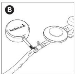
text_image
B barbecue
text_image
barbecue C
text_image
D barbecuenatural_image
Technical line drawing of a mechanical component with a shaft and housing, showing a directional arrow (no text or symbols)
natural_image
Simple line drawing of a lever with two circular ends and a central pivot point (no text or symbols)natural_image
Technical line drawing of a mechanical component with internal compartments and a directional arrow indicating motion (no text or symbols)5 Upravljalni gumb enega gorilnika nastavite na HIGH (Visoko).

natural_image
Three identical wire mesh panels arranged horizontally, each with a central slot and two small circular holes (no text or symbols)natural_image
Diagram of a bottle with spiderweb pattern and two butterflies (no text or symbols)
natural_image
Diagram of a car interior showing a lever mechanism with a wrench and screwdriver (no text or symbols)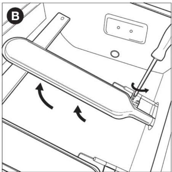
natural_image
Technical line drawing of a mechanical component with directional arrows indicating motion (no text or symbols)
natural_image
Technical line drawing of a mechanical assembly with three curved components and rotational arrows indicating motion (no text or symbols)2 Gorilnike in venturijeve cevi očistite z majhno krtačo ali z doma narejenim pripomočkom za čiščenje cevi (raztegnjeno sponko za papir, krtačo za cevi itd.).
natural_image
Technical line drawing of a medical device with two views: top shows a cylindrical device with attached cable, bottom shows a circular device with a ring and connector (no text or symbols)natural_image
Technical line drawing of a mechanical component with three top views and a downward arrow indicating assembly or disassembly (no text or symbols present)4.3 Emajl
natural_image
Diagram of a mechanical assembly with threaded connectors and an upward arrow indicating motion (no text or symbols)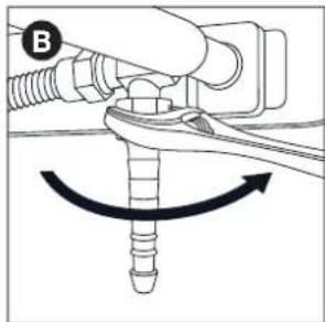
natural_image
Mechanical diagram showing a screw being inserted into a pipe with a curved arrow indicating rotation (no text or symbols)2 Nataknite crijevo na spojku (C) i pritegnite stezni prsten pomoću križnog odvijača (D).

natural_image
Mechanical diagram showing a pipe fitting with a threaded connector and an upward arrow indicating motion (no text or symbols)
text_image
Technical diagram showing pipe connection with labeled components D and G6.3.2 S POJKA B
Potreban Vam je ključ od 22 mm i podesivi ključ.
natural_image
Mechanical diagram showing a lever mechanism with a curved arrow indicating rotational motion (no text or symbols present)natural_image
Mechanical diagram showing a pipe fitting with a valve and directional arrow (no text or symbols)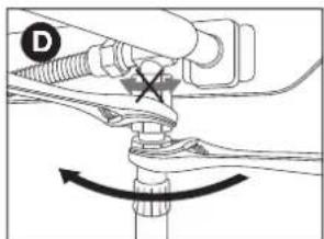
natural_image
Mechanical diagram showing a lever mechanism with rotating components and a star symbol (no text or labels)natural_image
Technical line drawing of a mechanical measurement setup with a tool and ring (no text or symbols)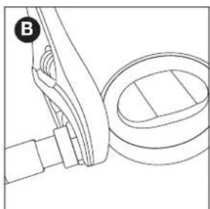
natural_image
Line drawing of a mechanical assembly with a lever and housing (no text or symbols)2 Priključite regulator pritiska na spremnik s plinom. Učinite jedno od navedenog:
natural_image
Technical line drawing of a mechanical assembly with no visible text or symbols
natural_image
Line drawing of a mechanical device with no visible text or symbols6.5 Zamjena spremnika
1 Zatvorite dovod plina i postavite sve kontrolne čvorove na OFF.
2 Odspojite prazni spremnik i priključite puni spremnik.
3 Provjerite spremnik, crijeva i sve plinske spojeve zbog curenja. Pogledajte "7 Provjera curenja plina".
7 PROVJERA CURENJA PLINA
natural_image
Line drawing of a toothpaste brush with 'barbecook' label on the head (no other text or symbols)7.5 Kako biste provjerili curenje plina
natural_image
Pure mechanical diagram showing a lever mechanism with no text or symbols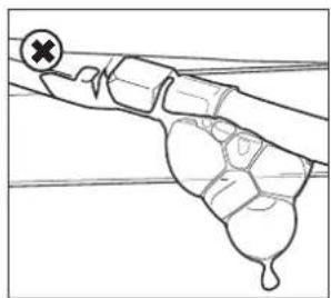
natural_image
Simple line drawing of a hand holding a tool or device against a horizontal line, with no text or symbols present.Kako biste provjerili curenje plina postupite na sljedeći način:
natural_image
Line drawing of a gas cylinder with a side cover and two arrows indicating flow direction (no text or symbols)
text_image
B barbecue
text_image
barbecue C
text_image
D barbecockVaš regulator pritiska i spojka mogu biti drugačiji od onih prikazanih na slikama.
6 Učinite jedno od navedenog:
natural_image
Diagram of a mechanical component with a lever and directional arrow (no text or symbols)natural_image
Simple line drawing of a lever with two circular ends and a central rod (no text or symbols)2 Otvorite poklopac i postavite kontrolne čvorove glavnih plamenika na OFF.
3 Ako nijedan plamenik još nije upaljen, otvorite dovod plina i pričekajte deset sekundi. Na taj način se plin stigne stabilizirati.
4 Zapalite šibicu i držite je otprilike 13 mm od plamenika.

natural_image
Technical line drawing of a mechanical component with internal compartments and a directional arrow (no text or symbols)5 Postavite kontrolni čvor jednog plamenika na HIGH.

Uvijek za početak upalite jedan glavni plamenik. Nikad nemojte paliti sve glavne plamenike odjednom.
natural_image
Three identical wire mesh grating panels arranged horizontally (no text or symbols)10.7 Iskorištavanje toplinskih zona
natural_image
Diagram of a cylindrical container with internal spiderweb structure and two small insects (no text or symbols)
Oštećenja nastala zbog blokiranih plamenika i redukcijskih cijevi smatraju se neodgovarajućim načinom održavanja i nisu pokrivena jamstvom.
11.3.2 KADA JE POTREBNO ČISTITI PLAMENIKE I REDUKCIJSKE CIJEVI?
Morate čistiti plamenike i redukcijske cijevi Vašeg uređaja:
- Prije prve uporabe nakon dugog razdoblja nekorištenja.
- Najmanje dvaput godišnje, od čega jednom na početku sezone.
11.3.3 KAKO BISTE OČISTILI PLAMENIKE I REDUKCIJSKE CIJEVI
natural_image
Technical diagram of a mechanical assembly with a wrench and screwdriver inserted into a component (no text or symbols)
natural_image
Technical diagram of a mechanical assembly with directional arrows indicating motion (no text or symbols)
natural_image
Technical line drawing of a mechanical assembly with three curved components and rotational arrows indicating motion (no text or symbols)text_image
Exploded view diagram of a solar panel assembly with numbered parts for identification and assembly reference.STELLA 4311
223.9423.000
| 1 22 | 7.9420.010 41 | ● | 227.9420.450 | ● | ||
| 2 | 227.9421.010 | 42 | 227.9423.100 | |||
| 3 | 227.9320.090 | 43 | 227.9420.130 | ★ | ||
| 4 | 227.9420.260 | 44 | 227.9423.110 | |||
| 5 | 227.9420.060 | |||||
| 6 | 227.9900.082 | ■ | ||||
| 7 | 227.9421.020 | |||||
| 8 | 227.9421.030 | ● | ||||
| 9 | 227.9423.010 | ● | ||||
| 10 | 227.9423.020 | ● | ||||
| 11 | 227.9423.030 | ● | ||||
| 12 | 227.9421.070 | ● | ||||
| 13 | 227.9420.040 | ● | ||||
| 14 | 227.9421.080 | ● | ||||
| 15 | 227.9421.090 | ● | ||||
| 16 | 227.9423.040 | ■ | ||||
| 17 | 227.9421.100 | ■ | ||||
| 18 | 227.9900.210 | |||||
| 19 | 227.9900.230 | |||||
| 20 | 227.9423.050 | |||||
| 21 | 227.9900.710 | |||||
| 22 | 227.9900.670 | |||||
| 23 | 227.9900.690 | |||||
| 24 | 227.9420.570 | ■ | ||||
| 25 | 227.9423.060 | |||||
| 26 | 227.9420.580 | |||||
| 27 | 227.9423.070 | ■ | ||||
| 28 | N/A | |||||
| 29 | 227.9900.755 | ■ | ||||
| 30 | 227.9423.080 | ★■ | ||||
| 31 | 227.9423.090 | |||||
| 32 | 227.9900.400 | ■ | ||||
| 33 | 227.9900.440 | |||||
| 34 | 227.9420.460 | ■ | ||||
| 35 | 227.9420.430 | ★■ | ||||
| 36 | 227.9420.440 | ★ | ||||
| 37 | 227.9900.570 | ● | ||||
| 38 | 227.9900.630 | |||||
| 39 | 227.9400.090 | |||||
| 40 | 227.9400.100 |
1

2

text_image
D X8 E X83
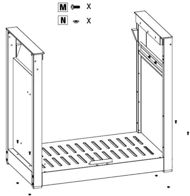
text_image
M X N X4

natural_image
Technical line drawing of a metal enclosure with internal compartments and mounting brackets (no text or symbols)5
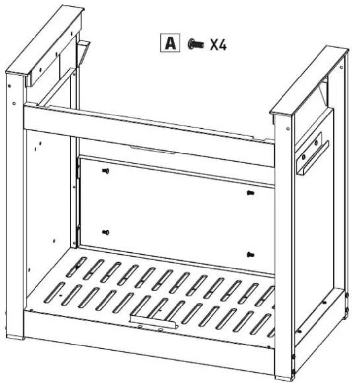
natural_image
Technical line drawing of a metal enclosure with perforated base and support frame (no text or symbols)6

text_image
1ST 2ND 3RD7

natural_image
Line drawing of a portable electric grill with control panel and wheels (no text or symbols)8

natural_image
Technical line drawing of a mechanical device with wheels and a curved top component (no text or symbols)9
A X4
E X4
H ⊙ X4

text_image
Technical diagram of a portable electric stove with labeled components and close-up insets showing internal wiring connections.10
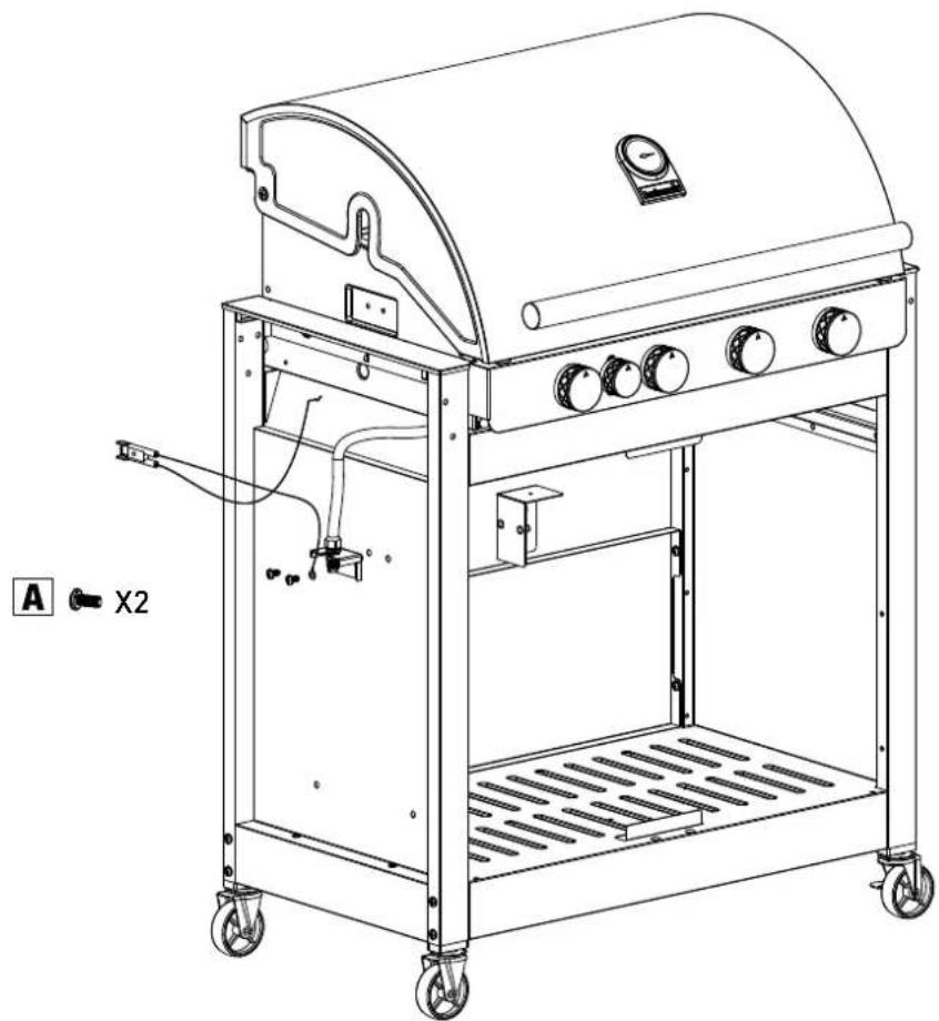
natural_image
Technical line drawing of a portable gas stove with wheels and control panel (no text or symbols)11

text_image
S X112

natural_image
Technical line drawing of a rectangular enclosure with internal components and a curved handle (no text or symbols)13

text_image
I X2 J X2 E X214

natural_image
Line drawing of a portable electric grill with wheels and control panel (no text or symbols)15
U X6

natural_image
Technical line drawing of a mechanical housing or enclosure with mounting holes and internal components (no text or symbols)16
M X4
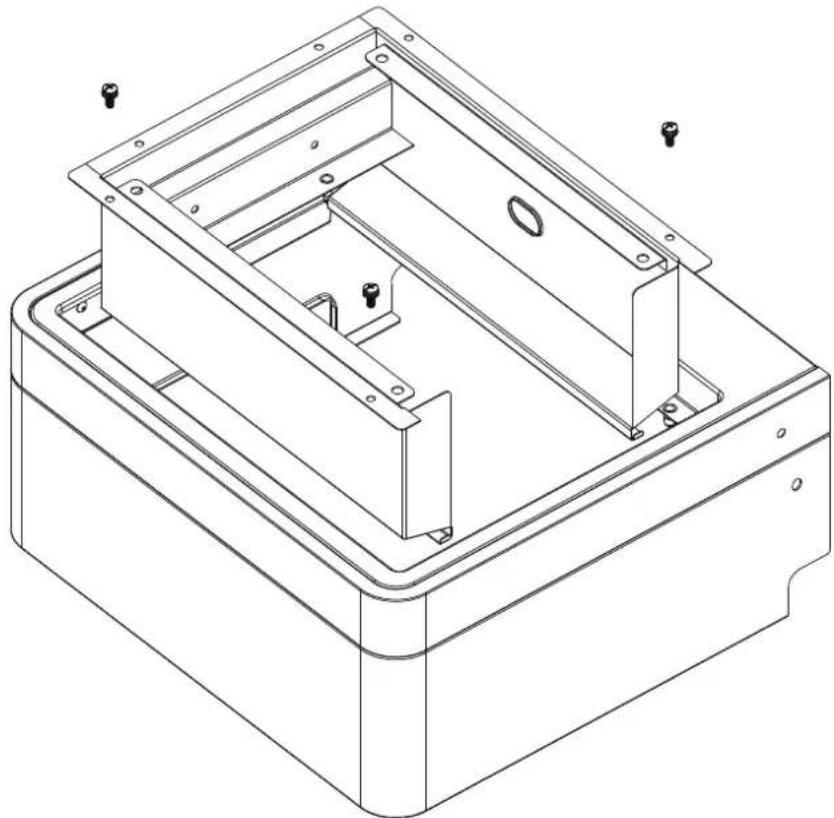
natural_image
Technical line drawing of a mechanical housing or enclosure with mounting brackets and mounting holes (no text or symbols)17

natural_image
Technical line drawing of a mechanical device with an open lid and internal compartments (no text or symbols)18

natural_image
Line drawing of a gas stove grater with control panel and wheels (no text or symbols)19

text_image
R I R I X2 I X3 E X520

text_image
M X2 2ND 1ST21
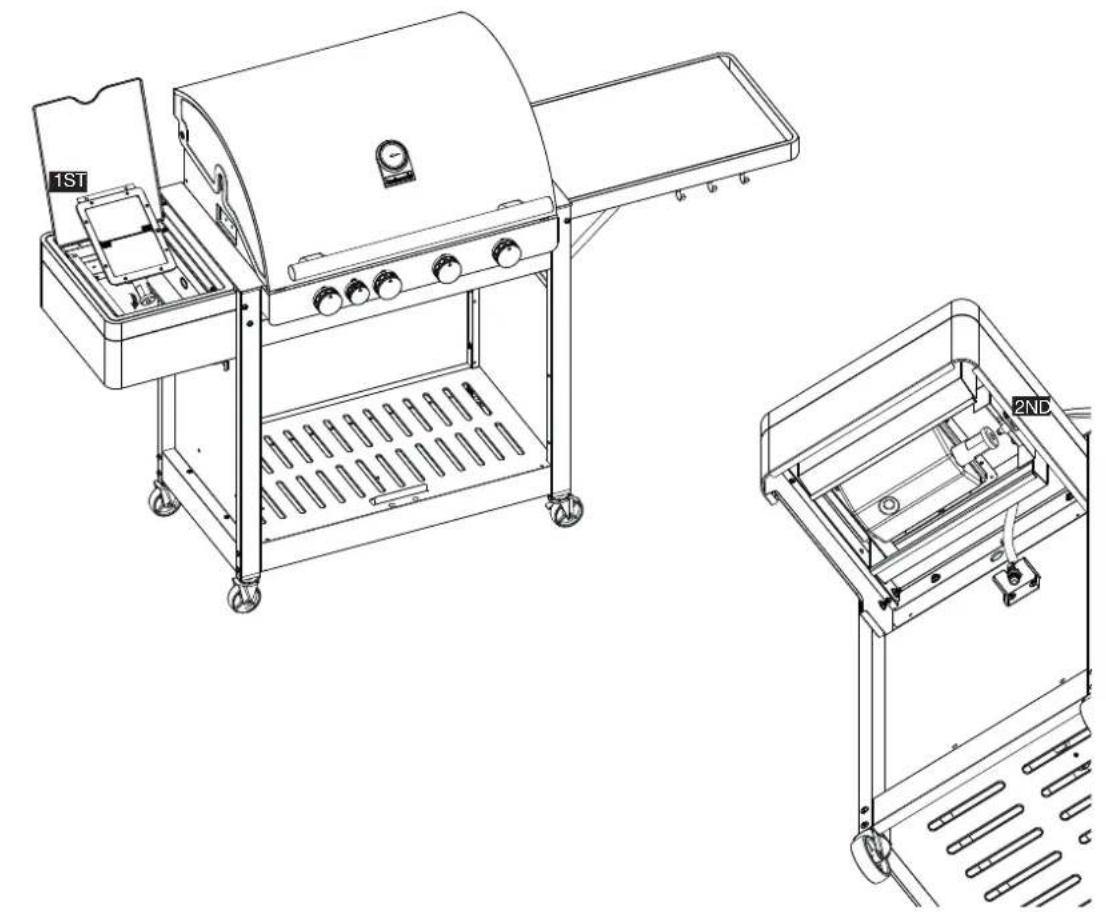
natural_image
Technical line drawing of a two-tiered outdoor grill with labeled components (1ST and 2ND), no text or symbols present.22

text_image
M X223
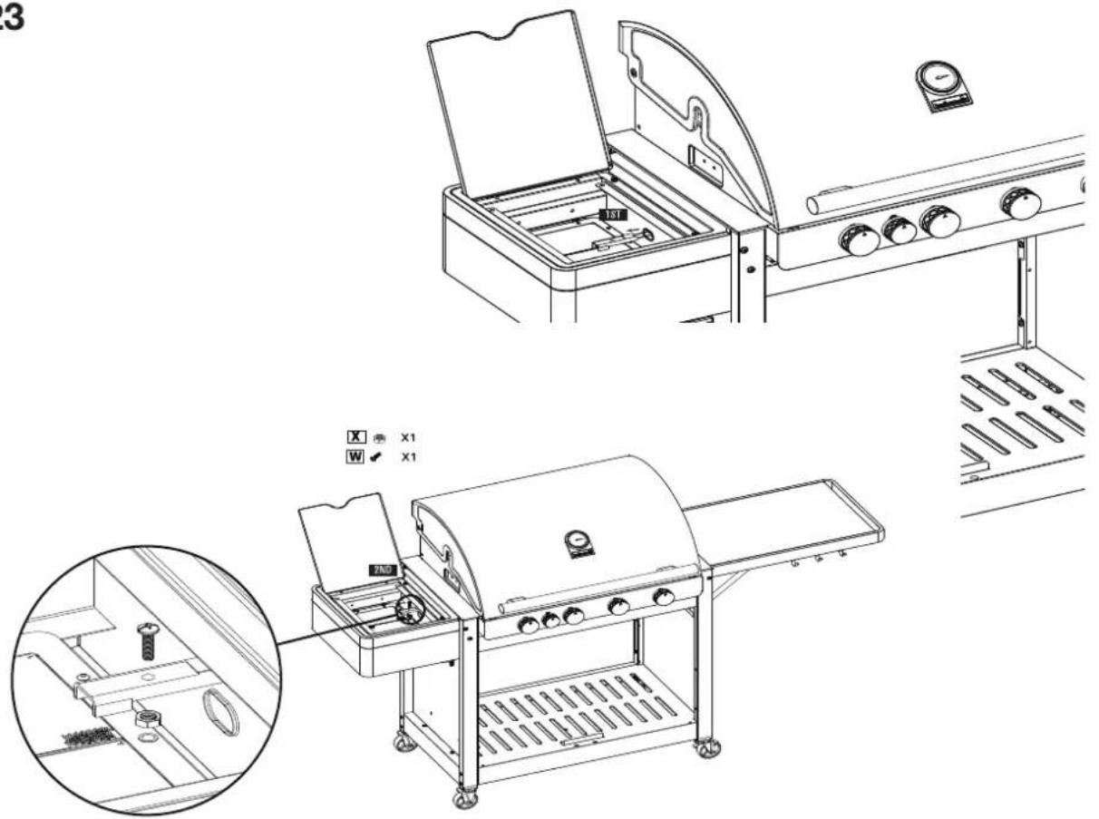
text_image
Technical line drawing of a gas stove with labeled components and cross-sectional views24
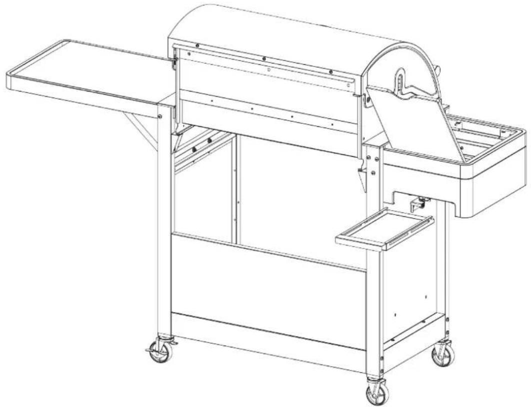
natural_image
Technical line drawing of a mechanical device with wheels and a curved handle (no text or symbols)25

natural_image
Line drawing of a standard electric grill with control panel and wheels (no text or symbols)26
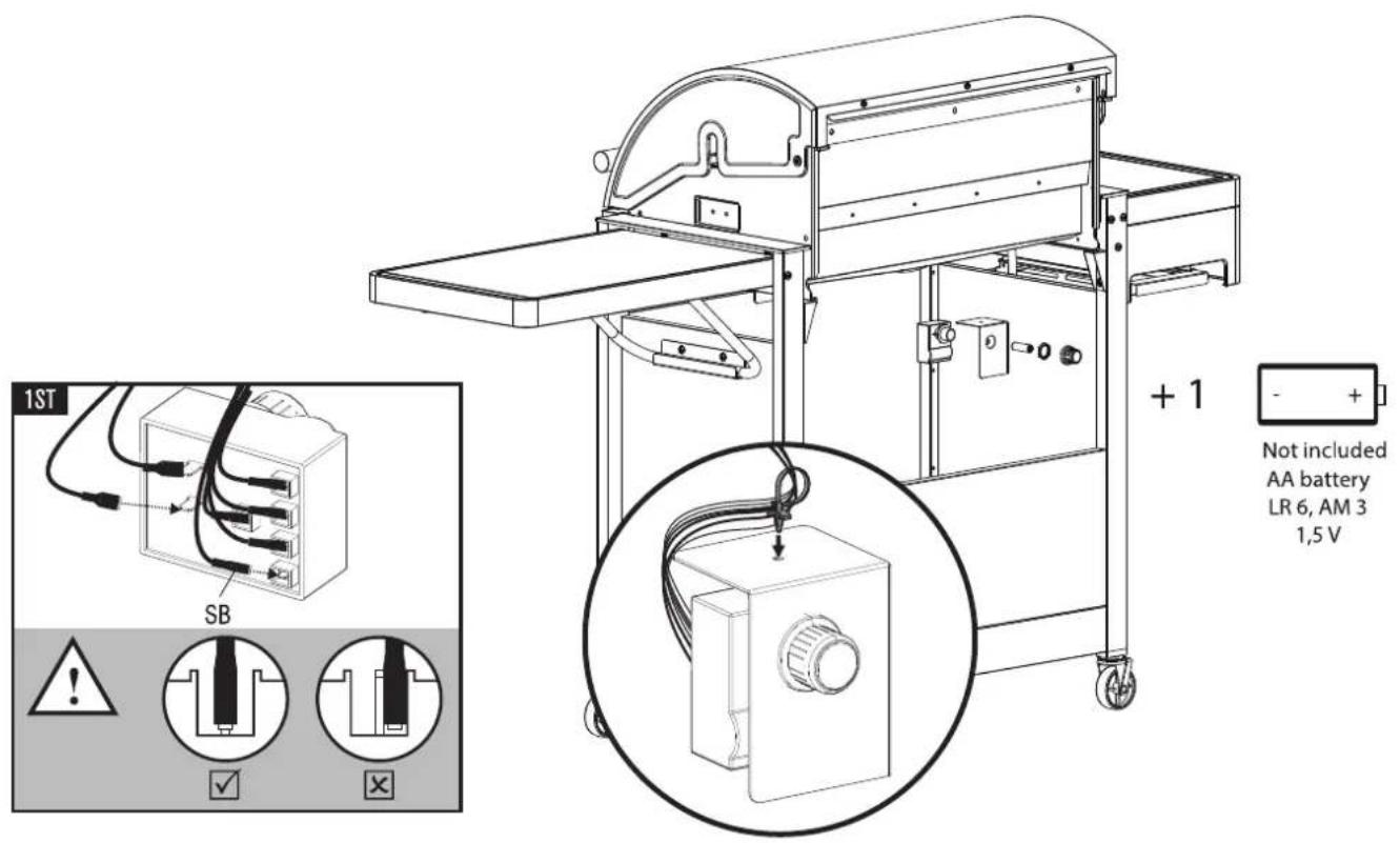
text_image
1ST SB + 1 Not included AA battery LR 6, AM 3 1,5 V27

natural_image
Technical line drawing of a mechanical cart with wheels and a curved top component (no text or symbols)28

natural_image
Line drawing of a portable electric grill with open doors and wheels, showing internal components and a close-up inset (no text or symbols)29
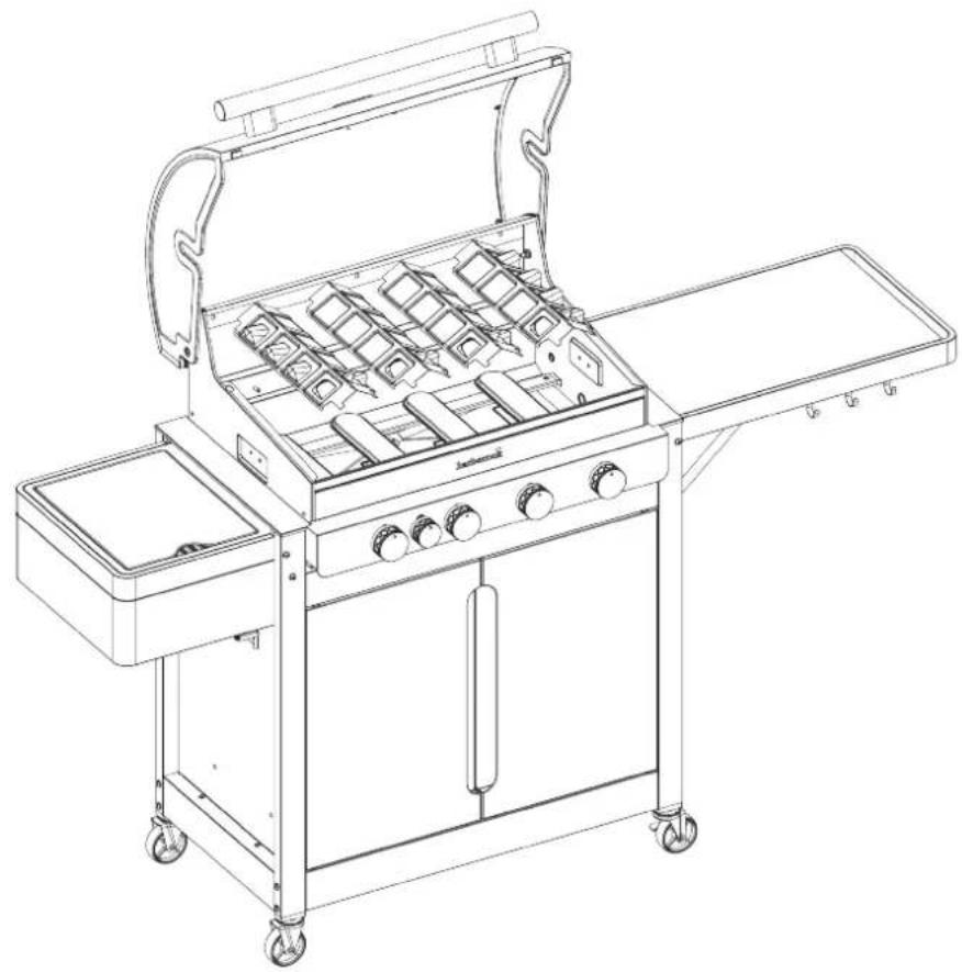
natural_image
Line drawing of a standard electric grill with open doors, grilles, and wheels (no text or symbols)30

natural_image
Line drawing of a 3D grill with grating and side table, no text or symbols present
natural_image
Line drawing of a standard electric grill with open lid, grilles, and wheels (no text or symbols)31

natural_image
Line drawing of a standard electric grill with open lid, grating tray, and wheels (no text or symbols)32

natural_image
Line drawing of a standard 3D grill with mounted dish, wheels, and control panel (no text or symbols)
natural_image
Line drawing of a portable electric stove with wheels and control panel (no text or symbols)| A | B | C | D | E | F | G | H | I | J | ||||||
| G30 | G31 | G30 | G31 | G30 | G31 | ||||||||||
| barbecook® | STELLA 4311 (G43921) Gas barbecue | LU - NL - DK - FI - SE - CY - CZ - EE - LT - MT - SK - SI - BG - IS - NO TR - HR - RO - IT - HU - LV | 28-30 mbar | propane, butane or their mixtures | I 3 B/P (30) | 1,5 V battery (not included) | 15.5 kW | 1128 g/h | 1108 g/h | 12.8 kW | 931 g/h | 915 g/h | 2.7 kW | 196 g/h | 193 g/h |
| BE - FR - IT - LU - IE - GB - GR - PT - ES - CY - CZ - LT - SK - CH SI - LV | 28-30 mbar | butane | I 3 + (28-30/37) | 15.5 kW | 1128 g/h | 1108 g/h | 12.8 kW | 931 g/h | 915 g/h | 2.7 kW | 196 g/h | 193 g/h | |||
| 37 mbar | propane | ||||||||||||||
Insulter hoofdbrander - Injecteur brûleur principale - Injector main burner - Injektor Hauptarenner - Iniettore bruclatore capo - Inyector para hornilla principal - Injector quelimador lateral - Insprutningspumpen head gasbrännaren - Den store branders dysetype - Suutin pääpolittimen - Tryska hlavnich hořakú - Tryska bocnych hořakov Type - Typ - Tipo - Typppi: 0,89 (28-30-37 mbar) Insulter zilbrander - Injecteur brûleur latérale - Injector side burner - Injektor Seitenkocher - Iniettore bruclatore laterale - Inyector para hornilla lateral - Injector quelimador lateral - Insprutningspumpen side gasbrännaren - Side branders dysetype - Suutin sivupoltimen - Tryska bocniho hořaku - Tryska bocnych hořakov - Type - Typ - Tipo - Typppi: 0,82 (28-30-37 mbar)
A: Merk - Marque - Marke - Brand - Mapka - Značka - Marke - Mórko - Marca - Kaubamárk - Tuctemerkki - robná marka - Márka - Ženklas - Prećzíme - Merke - Marka - Marca - Marca - Značka - Znamka - Márke B: Model - Appliance model - Modell des Geräts - Appliance model - Model na yreda - Model zařízeni - Maskinens model - Movršlo duokkuřík - Modelo de aparato - Seadme mudel - Laitteen malli - model uređaja - A keszůlek típusa - Modello apparecchio - Prietaiso modelis - líricos modelis - Modell - Model stosowania - Modelo do aparolho - Modelul aparatului - Model zariadenia - Model naprave - Anordningsmodell
C: Land van bestemming : Pays de destination - Landesbezeichnung - Country indentifikation - Vijmefikaapija ká čtrpanařa - Identifikace země - Identifikationsland - Xúpa tautotolönç - Identificador de país - Rligitáhs - Maan tunnistus - država za identifikaciju - Származási ország - Paese - Identifikuojama šalis - Identifikácijas valsts - Opprinnelseland - Identifikacja kraju - Identificação do país - Tara de identificare - Identifikacija krajiny - Identifikacija država - Landsidentifikation D: Gas druk - Pression de gaz - Gasdruck - Gas Pressure - raa pod náhrane - Tlak plynu - gastryk - H mison aspíou - La presión del gas - gaasi rôhik - kaasun paine - tlak plina - Gáznyomás - duju slégló reguliavimo - gazes spledlena - gasstrykk - preslone gaz - pressione del gas - pressão do gás - tlak plynu - pritisk plina - Gastryck
TYP-STELLA 4311-BBC190805.A

Home & Garden
Blokkestraat 41A
B-8550, Zwevegem, Belgium
- 用 10% 乘
CE 2531/19 PIN: 2531CS-0076
text_image
GRILL MASTER barbecookREGISTER NOW & GET ACCESS TO:

text_image
barbcss MY PRODUCERS / BARBDCODEN EOGON BLACK ACCESSORIES SPRING PRAVE NOMBLES MINTANTY• Online Product Manuals
• Personalised Grillspiration
• Product Tips & Tricks
• Barbecook Challenges
- Spare Parts Lists
...
WWW.BARBECOOK.COM
Barbecook® is a registered trade mark of SAEY Home & Garden N.V. Blokkestraat 41A, B-8550, Zwevegem, Belgium
