SST1800 - Saw STANLEY - Free user manual and instructions
Find the device manual for free SST1800 STANLEY in PDF.
| Product Type | Table Saw |
| Brand | STANLEY |
| Model | SST1800 |
| Input Voltage | 230 V AC, 50 Hz |
| Rated Power Input | 1800 W |
| No-Load Speed | 4800 min⁻¹ |
| Blade Diameter | 254 mm |
| Arbor Size | 30 mm |
| Max Cutting Depth at 90° | 80 mm |
| Max Cutting Depth at 45° | 50 mm |
| Blade Bevel Range | 0 - 45° |
| Table Dimensions | 560 x 680 mm |
| Weight | 28.8 kg |
| Sound Pressure Level (L_PA) | 87.5 dB(A) |
| Sound Power Level (L_WA) | 103.5 dB(A) |
| Sound Uncertainty (K) | 3 dB(A) |
| Safety Devices | Blade guard, riving knife, anti-kickback, overload protection |
| Main Functions | Rip cuts, cross cuts, bevel cuts, dado cuts (with accessories) |
| Package Contents | Table saw, 60-tooth blade, blade guard, miter gauge, rip fence, dust extraction hose, adapter, wrenches, push stick, fine work guard, manual |
| Maintenance and Cleaning | Clean with a dry cloth, blow out ventilation openings, do not use solvents |
| Spare Parts and Repairability | Have repairs done by an authorized service center, use identical replacement parts |
| Compliance Standards | 2006/42/EC, EN62841-1, EN62841-3-1, 2014/30/EU, 2011/65/EU |
Frequently Asked Questions - SST1800 STANLEY
User questions about SST1800 STANLEY
0 question about this device. Answer the ones you know or ask your own.
Ask a new question about this device
Download the instructions for your Saw in PDF format for free! Find your manual SST1800 - STANLEY and take your electronic device back in hand. On this page are published all the documents necessary for the use of your device. SST1800 by STANLEY.
USER MANUAL SST1800 STANLEY
English (original instructions) 29
text_image
Technical diagram of a STAGLEY coordinate system with numbered components for identificationnatural_image
Technical line drawing of a mechanical assembly with no visible text or symbolsFig. R
text_image
21 6 4 22Fig. S
natural_image
Technical line drawing of a mechanical device with labeled components (no readable text or symbols)Fig. T
text_image
Technical diagram of a mechanical device with numbered components and labeled partsFig. U
text_image
0476.00 23BORDSAV
SST1800
Tillykke!
Director – Outdoor Products Group
STANLEY Europe, Egide Walschaertsstraat14-18,
2800 Mechelen, Belgien
03.08.2021

Symbol for sikkerhedsadvarsel
/min. Omdrejninger eller reciprociteter i minuttet

You have chosen a STANLEY tool. Years of experience, thorough product development and innovation make STANLEY one of the most reliable partners for professional power tool users.
Technical Data
| SST1800 | ||
| Voltage V | AC | 230 |
| Type | 2 | |
| Frequency Hz 50 | ||
| Power input W 1800 | ||
| No load speed min | -1 | 4800 |
| Blade diameter mm 254 | ||
| Bore Size mm 30 | ||
| Blade kerf mm 2.8 | ||
| Blade body thickness mm 1.8 | ||
| Riving knife thickness mm 2.5 | ||
| Table size | mm | 560x680 |
| Max. cutting depth at 45° | mm 50 | |
| Max. cutting depth at 90° | mm 80 | |
| Blade bevel range | ° | 0–45° |
| Weight | kg 28.8 | |
| Noise values and/or vibration values (triax vector sum) according to EN62841-3-1: | ||
| L_PA (emission sound pressure level) | dB(A) | 87.5 |
| L_WA (sound power level) | dB(A) | 103.5 |
| K(uncertainty for the given sound level) | dB(A) | 3 |
The vibration and/or noise emission level given in this information sheet has been measured in accordance with a standardised test given in EN62841 and may be used to compare one tool with another. It may be used for a preliminary assessment of exposure.
WARNING: The declared vibration and/or noise emission is represents the main applications of the tool. However if the tool is used for different applications, with different accessories or poorly maintained, the vibration and/or noise emission may differ. This may significantly increase the exposure level over the total working period.
An estimation of the level of exposure to vibration and/or noise should also take into account the times when the tool is switched off or when it is running but not actually doing the job. This may significantly reduce the exposure level over the total working period.
Identify additional safety measures to protect the operator from the effects of vibration and/or noise such as: maintain the tool and the accessories, keep the hands warm (relevant for vibration), organisation of work patterns.
EC-Declaration of Conformity
Machinery Directive

Table Saw
SST1800
STANLEY declares that these products described under
Technical Data are in compliance with:
2006/42/EC,EN62841-1:2015+AC:2015,EN62841-3-
1:2014+AC:2015+A11:2017.
These products also comply with Directive 2014/30/EU and 2011/65/EU. For more information, please contact STANLEY at the following address or refer to the back of the manual.
The undersigned is responsible for compilation of the technical file and makes this declaration on behalf of STANLEY.

Becky Cotsworth
Director – Outdoor Products Group
STANLEY Europe, Egide Walschaertsstraat14-18,
2800 Mechelen, Belgium
03.08.2021

WARNING: To reduce the risk of injury, read the
instruction manual.
Definitions: Safety Guidelines
The definitions below describe the level of severity for each signal word. Please read the manual and pay attention to these symbols.
DANGER: Indicates an imminently hazardous solution which, if not avoided, will result in death or serious injury.
WARNING: Indicates a potentially hazardous situation, if not avoided, could result in death or serious injury.
CANTION: Indicates a potentially hazardous situation which, if not avoided, may result in minor or moderate injury.
NOTICE: Indicates a practice not related to personal injury which, if not avoided, may result in property damage.
Davates risk of electric shock.
Diabetes risk of fire.
GENERAL POWER TOOL SAFETY WARNINGS
WARNING: Read all safety warnings, instructions, illustrations and specifications provided with this power tool. Failure to follow all instructions listed below may result in electric shock, fire and/or serious injury.
SAVE ALL WARNINGS AND INSTRUCTIONS FOR FUTURE REFERENCE
The term "power tool" in the warnings refers to your mains-operated (corded) power tool or battery-operated (cordless) power tool.
1) Work Area Safety
a) Keep work area clean and well lit. Cluttered or dark areas invite accidents.
b) Do not operate power tools in explosive atmospheres, such as in the presence of flammable liquids, gases or dust. Power tools create sparks which may ignite the dust or fumes.
c) Keep children and bystanders away while operating a power tool. Distractions can cause you to lose control.
2) Electrical Safety
a) Power tool plugs must match the outlet. Never modify the plug in any way. Do not use any adapter plugs with earthed (grounded) power tools.
Unmodified plugs and matching outlets will reduce risk of electric shock.
b) Avoid body contact with earthed or grounded surfaces, such as pipes, radiators, ranges and refrigerators. There is an increased risk of electric shock if your body is earthed or grounded.
c) Do not expose power tools to rain or wet conditions. Water entering a power tool will increase the risk of electric shock.
d) Do not abuse the cord. Never use the cord for carrying, pulling or unplugging the power tool. Keep cord away from heat, oil, sharp edges or moving parts. Damaged or entangled cords increase the risk of electric shock.
e) When operating a power tool outdoors, use an extension cord suitable for outdoor use. Use of a cord suitable for outdoor use reduces the risk of electric shock.
f) If operating a power tool in a damp location is unavoidable, use a residual current device (RCD) protected supply. Use of an RCD reduces the risk of electric shock.
3) Personal Safety
a) Stay alert, watch what you are doing and use common sense when operating a power tool. Do not use a power tool while you are tired or under the influence of drugs, alcohol or medication. A moment of inattention while operating power tools may result in serious personal injury.
b) Use personal protective equipment. Always wear eye protection. Protective equipment such as a dust mask, non-skid safety shoes, hard hat or hearing protection used for appropriate conditions will reduce personal injuries.
c) Prevent unintentional starting. Ensure the switch is in the off-position before connecting to power source and/or battery pack, picking up or carrying the tool. Carrying power tools with your finger on the switch or energising power tools that have the switch on invites accidents.
d) Remove any adjusting key or wrench before turning the power tool on. A wrench or a key left attached to a rotating part of the power tool may result in personal injury.
e) Do not overreach. Keep proper footing and balance at all times. This enables better control of the power tool in unexpected situations.
f) Dress properly. Do not wear loose clothing or jewellery. Keep your hair and clothing away from moving parts. Loose clothes, jewellery or long hair can be caught in moving parts.
g) If devices are provided for the connection of dust extraction and collection facilities, ensure these are connected and properly used. Use of dust collection can reduce dust-related hazards.
h) Do not let familiarity gained from frequent use of tools allow you to become complacent and ignore tool safety principles. A careless action can cause severe injury within a fraction of a second.
4) Power Tool Use and Care
a) Do not force the power tool. Use the correct power tool for your application. The correct power tool will do the job better and safer at the rate for which it was designed.
b) Do not use the power tool if the switch does not turn it on and off. Any power tool that cannot be controlled with the switch is dangerous and must be repaired.
c) Disconnect the plug from the power source and/or remove the battery pack, if detachable, from the power tool before making any adjustments, changing accessories, or storing power tools. Such preventive safety measures reduce the risk of starting the power tool accidentally.
d) Store idle power tools out of the reach of children and do not allow persons unfamiliar with the power tool or these instructions to operate the power tool. Power tools are dangerous in the hands of untrained users.
e) Maintain power tools and accessories. Check for misalignment or binding of moving parts, breakage of parts and any other condition that may affect the power tool's operation. If damaged, have the power tool repaired before use. Many accidents are caused by poorly maintained power tools.
f) Keep cutting tools sharp and clean. Properly maintained cutting tools with sharp cutting edges are less likely to bind and are easier to control.
g) Use the power tool, accessories and tool bits etc. in accordance with these instructions, taking into account the working conditions and the work to be performed. Use of the power tool for operations different from those intended could result in a hazardous situation.
h) Keep handles and grasping surfaces dry, clean and free from oil and grease. Slippery handles and grasping surfaces do not allow for safe handling and control of the tool in unexpected situations.
5) Service
a) Have your power tool serviced by a qualified repair person using only identical replacement parts. This will ensure that the safety of the power tool is maintained.
Safety Instructions for Table Saws
1) Guarding Related Warnings
a) Keep guards in place. Guards must be in working order and be properly mounted. A guard that is loose, damaged, or is not functioning correctly must be repaired or replaced.
b) Always use saw blade guard, riving knife and anti-kickback pawls for every through-cutting operation. For through-cutting operations where the saw blade cuts completely through the thickness of the workpiece, the guard and other safety devices help reduce the risk of injury.
c) Immediately reattach the guarding system after completing an operation (such as rabbeting cuts) which requires removal of the guard, riving knife and/or anti-kickback device. The guard, riving knife, and anti-kickback device help to reduce the risk of injury.
d) Make sure the saw blade is not contacting the guard, riving knife or the workpiece before the switch is turned on. Inadvertent contact of these items with the saw blade could cause a hazardous condition.
e) Adjust the riving knife as described in this instruction manual. Incorrect spacing, positioning and alignment can make the riving knife ineffective in reducing the likelihood of kickback.
f) For the riving knife and anti-kickback pawls to work, they must be engaged in the workpiece. The riving knife and anti-kickback pawls are ineffective when cutting workpieces that are too short to be engaged with the riving knife and anti-kickback pawls. Under these conditions a kickback cannot be prevented by the riving knife and anti-kickback pawls.
g) Use the appropriate saw blade for the riving knife. For the riving knife to function properly, the saw blade diameter must match the appropriate riving knife and the body of the saw blade must be thinner than the thickness of the riving knife and the cutting width of the saw blade must be wider than the thickness of the riving knife.
2) Cutting Procedures Warnings
a)

DANGER: Never place your fingers or hands in the vicinity or in line with the saw blade. A moment of inattention or a slip could direct your hand towards the saw blade and result in serious personal injury.
b) Feed the workpiece into the saw blade or cutter only against the direction of rotation. Feeding the
workpiece in the same direction that the saw blade is rotating above the table may result in the workpiece, and your hand, being pulled into the saw blade.
c) Never use the mitre gauge to feed the workpiece when ripping and do not use the rip fence as a length stop when cross cutting with the mitre gauge.
Guiding the workpiece with the rip fence and the mitre gauge at the same time increases the likelihood of saw blade binding and kickback.
d) When ripping, always apply the workpiece feeding force between the fence and the saw blade. Use a push stick when the distance between the fence and the saw blade is less than 150 mm, and use a push block when this distance is less than 50 mm. "Work helping" devices will keep your hand at a safe distance from the saw blade.
e) Use only the push stick provided by the manufacturer or constructed in accordance with the instructions. This push stick provides sufficient distance of the hand from the saw blade.
f) Never use a damaged or cut push stick. A damaged push stick may break causing your hand to slip into the saw blade.
g) Do not perform any operation "freehand". Always use either the rip fence or the mitre gauge to position and guide the workpiece. "Freehand" means using your hands to support or guide the workpiece, in lieu of a rip fence or mitre gauge. Freehand sawing leads to misalignment, binding and kickback.
h) Never reach around or over a rotating saw blade. Reaching for a workpiece may lead to accidental contact with the moving saw blade.
i) Provide auxiliary workpiece support to the rear and/or sides of the saw table for long and/or wide workpieces to keep them level. A long and/or wide workpiece has a tendency to pivot on the table's edge, causing loss of control, saw blade binding and kickback.
j) Feed workpiece at an even pace. Do not bend or twist the workpiece. If jamming occurs, turn the tool off immediately, unplug the tool then clear the jam. Jamming the saw blade by the workpiece can cause kickback or stall the motor.
k) Do not remove pieces of cut-off material while the saw is running. The material may become trapped between the fence or inside the saw blade guard and the saw blade pulling your fingers into the saw blade. Turn the saw off and wait until the saw blade stops before removing material.
1) Use an auxiliary fence in contact with the table top when ripping workpieces less than 2 mm thick. A thin workpiece may wedge under the rip fence and create a kickback.
3) Kickback Causes and Related Warnings
Kickback is a sudden reaction of the workpiece due to a pinched, jammed saw blade or misaligned line of cut in the workpiece with
respect to the saw blade or when a part of the workpiece binds between the saw blade and the rip fence or other fixed object.
Most frequently during kickback, the workpiece is lifted from the table by the rear portion of the saw blade and is propelled towards the operator.
Kickback is the result of saw misuse and/or incorrect operating procedures or conditions and can be avoided by taking proper precautions as given below.
a) Never stand directly in line with the saw blade. Always position your body on the same side of the saw blade as the fence. Kickback may propel the workpiece at high velocity towards anyone standing in front and in line with the saw blade.
b) Never reach over or in back of the saw blade to pull or to support the workpiece. Accidental contact with the saw blade may occur or kickback may drag your fingers into the saw blade.
c) Never hold and press the workpiece that is being cut off against the rotating saw blade. Pressing the workpiece being cut off against the saw blade will create a binding condition and kickback.
d) Align the fence to be parallel with the saw blade. A misaligned fence will pinch the workpiece against the saw blade and create kickback.
e) Use a featherboard to guide the workpiece against the table and fence when making non-through cuts such as rabbeting cuts. A featherboard helps to control the workpiece in the event of a kickback.
f) Support large panels to minimise the risk of saw blade pinching and kickback. Large panels tend to sag under their own weight. Support(s) must be placed under all portions of the panel overhanging the table top.
g) Use extra caution when cutting a workpiece that is twisted, knotted, warped or does not have a straight edge to guide it with a mitre gauge or along the fence. A warped, knotted, or twisted workpiece is unstable and causes misalignment of the kerf with the saw blade, binding and kickback.
h) Never cut more than one workpiece, stacked vertically or horizontally. The saw blade could pick up one or more pieces and cause kickback.
i) When restarting the saw with the saw blade in the workpiece, centre the saw blade in the kerf so that the saw teeth are not engaged in the material. If the saw blade binds, it may lift up the workpiece and cause kickback when the saw is restarted.
j) Keep saw blades clean, sharp, and with sufficient set. Never use warped saw blades or saw blades with cracked or broken teeth. Sharp and properly set saw blades minimise binding, stalling and kickback.
4) Table Saw Operating Procedure Warnings
a) Turn off the table saw and disconnect from the power source when removing the table insert, changing the saw blade or making adjustments to the riving knife, anti-kickback pawls or saw blade
guard, and when the machine is left unattended. Precautionary measures will avoid accidents.
b) Never leave the table saw running unattended. Turn it off and don't leave the tool until it comes to a complete stop. An unattended running saw is an uncontrolled hazard.
c) Locate the table saw in a well-lit and level area where you can maintain good footing and balance. It should be installed in an area that provides enough room to easily handle the size of your workpiece. Cramped, dark areas, and uneven slippery floors invite accidents.
d) Frequently clean and remove sawdust from under the saw table and/or the dust collection device. Accumulated sawdust is combustible and may self-ignite.
e) The table saw must be secured. A table saw that is not properly secured may move or tip over.
f) Remove tools, wood scraps, etc. from the table before the table saw is turned on. Distraction or a potential jam can be dangerous.
g) Always use saw blades with correct size and shape (diamond versus round) of arbour holes. Saw blades that do not match the mounting hardware of the saw will run off-centre, causing loss of control.
h) Never use damaged or incorrect saw blade mounting means such as flanges, saw blade washers, bolts or nuts. These mounting means were specially designed for your saw, for safe operation and optimum performance.
i) Never stand on the table saw, do not use it as a stepping stool. Serious injury could occur if the tool is tipped or if the cutting tool is accidentally contacted.
j) Make sure that the saw blade is installed to rotate in the proper direction. Do not use grinding wheels, wire brushes, or abrasive wheels on a table saw. Improper saw blade installation or use of accessories not recommended may cause serious injury.
Additional Safety Rules for Saw Benches
WARNING: Cutting plastics, sap coated wood, and other materials may cause melted material to accumulate on the blade tips and the body of the saw blade, increasing the risk of blade overheating and binding while cutting.
- Make sure that the blade rotates in the correct direction and that the teeth are pointing to the front of the saw bench.
- Be sure all clamp handles are tight before starting any operation.
- Be sure all blade and flanges are clean and the larger face of the clamp washer is against the blade. Tighten the arbor nut securely.
- Make sure that the riving knife is adjusted to the correct distance from the blade.
- Never operate the saw without the upper and lower guards in place.
- Do not apply lubricants to the blade when it is running.
• Always keep the push stick in its store place when not in use.
- Do not use the guard for handling or transportation.
- Do not exert side pressure on the saw blade.
- Never cut light alloy. The machine is not designed for this application.
- Do not use abrasive disc or diamond cutting wheels.
- Rabbeting, slotting or grooving is not allowed.
- In case of machine failure, immediately switch the machine off and remove from the power source. Report the failure and mark the machine in suitable form which prevents that other persons use the defective machine.
- When the saw blade is blocked due to abnormal feed force during cutting, ALWAYS switch the machine off and remove from the power source. Remove the workpiece and ensure that the saw blade runs free. Turn the machine on and start a new cutting operation with reduced feed force.
- NEVER attempt to cut a stack of loose pieces of material which could cause loss of control or kickback. Support all materials securely.
• Take care that the blade guard is properly positioned. When sawing, it must always face against the workpiece.
Saw Blades
- Do not use saw blades that do not conform to the dimensions stated in the Technical Data. Do not use any spacers to make a blade fit onto the spindle. Use only the blades specified in this manual, complying with EN847-1, if intended for wood and similar materials.
- The maximum speed of the saw blade shall always be greater than or at least equal to the speed marked on the rating plate of the tool.
- The saw blade diameter must be in accordance with the markings on rating plate of the tool.
- Consider applying specially designed noisereduction blades.
- Do not use high steel (HS) saw blades.
- Do not use cracked or damaged saw blades.
- Ensure that the chosen saw blade is suitable for the material to be cut.
• Always wear gloves for handling saw blades and rough material. Saw blades should be carried in a holder wherever practicable.
Power connections
Before connecting the machine to the power line, make sure the switch (8) is in the "OFF" position and be sure that the electric current is of the same characteristics as indicated on the machine. All line connections should make good contact. Running on low voltage will damage the machine.
DANGER! Do not expose the machine to rain or operate the machine in damp locations.
Before connecting the machine to the power source, make sure the switch is in the "OFF" position.
SAFETY OF OTHERS
- This appliance is not intended for use by persons (including children) with reduced physical, sensory or mental capabilities,
or lack of experience and knowledge, unless they have been given supervision or instruction concerning use of the appliance by a person responsible for their safety.
• Children should be supervised to ensure that they do not play with the appliance.
Residual Risks
WARNING: We recommend the use of a residual current device with a residual current rating of 30mA or less.
In spite of the application of the relevant safety regulations and the implementation of safety devices, certain residual risks cannot be avoided. These are:
- Impairment of hearing.
- Risk of personal injury due to flying particles.
- Risk of burns due to accessories becoming hot during operation.
- Risk of personal injury due to prolonged use.
SAVE THESE INSTRUCTIONS
Electrical Safety
The electric motor has been designed for one voltage only. Always check that the power supply corresponds to the voltage on the rating plate.

Your STANLEY tool is double insulated in accordance with EN62841; therefore no earth wire is required.
This product is intended to be used with a safety transformer manufactured to BSEN61558 and BS4343. Never work without this transformer in place.
If the supply cord is damaged, it must be replaced only by STANLEY or an authorised service organisation.
Mains Plug Replacement (U.K. & Ireland Only)
If a new mains plug needs to be fitted:
- Safely dispose of the old plug.
- Connect the brown lead to the live terminal in the plug.
- Connect the blue lead to the neutral terminal.
WARNING: No connection is to be made to the earth terminal.
Follow the fitting instructions supplied with good quality plugs. Recommended fuse: 13 A.
Using an Extension Cable
If an extension cable is required, use an approved 3-core extension cable suitable for the power input of this tool (see
Technical Data). The minimum conductor size is 1.5 mm ^2 ; the maximum length is 30 m.
When using a cable reel, always unwind the cable completely.
Package Contents
The package contains:
1Tablesaw
1 60T saw blade
ENGLISH
1Bladeguard
1 Mitergauge
1Ripfence
1Extractionhose
1 Hoseadapter
2Spannerwrench
1Pushstick
1 Narrow Material Fence
1 Instructionmanual
- Check for damage to the tool, parts or accessories which may have occurred during transport.
• Take the time to thoroughly read and understand this manual prior to operation.
Markings on Tool
The following pictograms are shown on the tool:

Read instruction manual before use.

Wear ear protection.

Wear eye protection.
V Volts
A Amperes
Hz Hertz
Watts
min minutes

Alternating current

Direct current

No-load speed

Class II Construction

Earthing terminal

Safety alert symbol
/min. Revolutions or Reciprocations per minute

Caution! Read the instruction manual for the correct adjustment and locking procedure for the Guard and Riving knife.
Description (Fig. A)
WARNING: Never modify the power tool or any part of it. Damage or personal injury could result.
1 Saw table
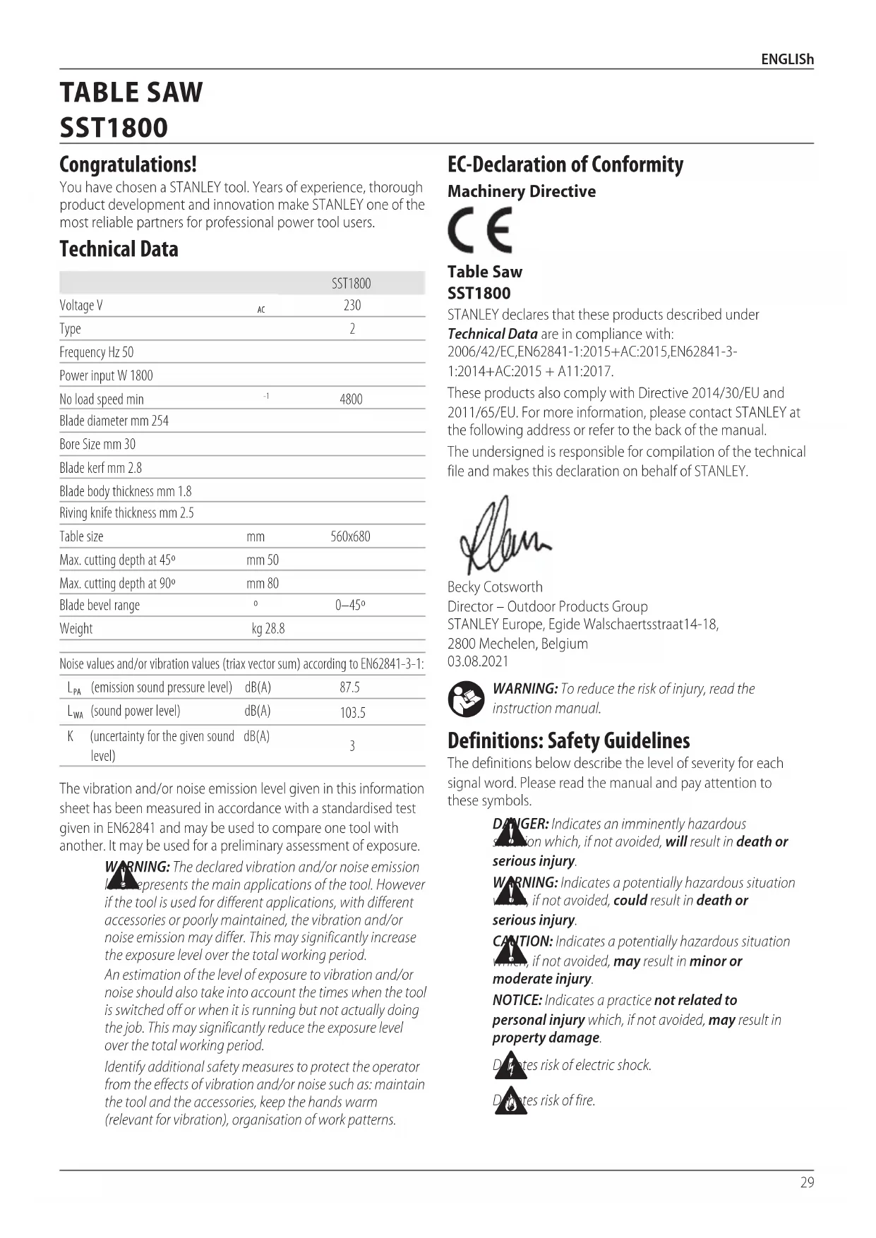
2 Blade guard
3 Riving knife
4 Saw blade
5 Rip fence
6 Mitre guage
7 Transportation wheels
8 On/Off switch
9 Leg stand
10 Bevel adjustment locking knob
11 Blade elevation handle
12 Leg stand locking knob
13 Blade tilting wheel
14 Locking handle for extension table
15 Locking handle for rip fence
16 Extension table
17 Spanner wrench
18 Guide rail
19 Push stick
20 Table insert
21 Groove (a)
22 Groove (b)
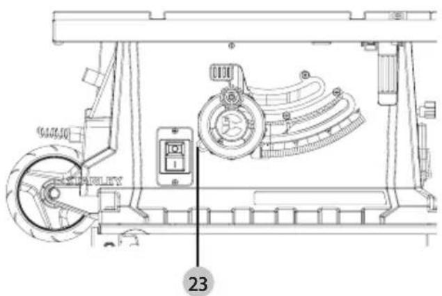
23 Overloaded protector
Intended Use
The SST1800 table saw is designed for professional ripping, cross-cutting, mitreing and bevelling with various materials as wood, wood composite materials and plastics.
DO NOT use under wet conditions or in the presence of flammable liquids or gases.
DO NOT use for cutting metal, cement board, or masonry.
DO NOT use shaping cutter heads on this saw.
DO NOT perform tapered cuts without a tapered jig accessory.
DO NOT use the saw for plunge or cove cutting.
These table saws are professional power tools.
DO NOT let children come into contact with the tool.
Supervision is required when inexperienced operators use this tool.
- Young children and the infirm. This appliance is not intended for use by young children or infirm persons without supervision.
- This product is not intended for use by persons (including children) suffering from diminished physical, sensory or mental abilities; lack of experience, knowledge or skills unless they are supervised by a person responsible for their safety. Children should never be left alone with this product.
ASSEMBLY AND ADJUSTMENTS
WARNING: To reduce the risk of serious personal injury, turn tool off and disconnect tool from power source before making any adjustments or removing/installing attachments or accessories. An accidental start-up can cause injury.
ASSEMBLY (Fig. A1, A2, A3, A4)
There are three positions on the machine for different use, standing, folding and transporting. The legs are locked using twist knobs which lock/unlock in either direction and have a central unlocked position.
- Start with the saw standing on its wheels (Fig. A1), unlock the upper legs. Swing up the legs and lock (Fig. A2) then unlock the lower legs.
- Lift the table from the end (Fig. A3), allowing the lower leg to swing into place. Swing the leg fully into place and lock (Fig. A4).
- There is a adjustable spring leg as shown in Fig. A5. You can rotate it clockwise or anti-clockwise for your desired length. (Fig. A5).
Folding Instructions (Fig. B1, B2, B3, B4)
Hold and support the table edge, unlock the legs at the wheel end (Fig. B1). Lower the wheels to the ground, allowing the legs to swing under (Fig. B2). Stand the table on end, fold up and lock the lower legs, unlock the upper legs (Fig. B3). Swing down the legs and lock (Fig. B4).
To Transport the Table Saw (Fig. C1, C2)
WARNING! Cover the upper part of the saw blade during transportation, for example by the guard.
The upper legs could be locked in the vertical position for use as a trolley handle.
Blade Elevation Handle Assembly (Fig. D)
Place washer 24, housing 25, washer 26 and hex nut 27 on the bolt 28 to assemble the blade elevation handle 11.
Riving Knife Set-Up (Fig. E, F, G)
WARNING! Disconnect the mains cable! The setup of the ring knife 3 must be checked before each use.
WARNING! The riving knife 3 should be delivered in the last position for through cutting. However, before first use and before connecting the machine to the power, make sure the riving knife is secure, in-line with the blade and the correct distance from the blade (refer to Fig F). Only work with the machine if the riving knife 3 is in the upper position unless the saw is being used for slitting operations. THE GUARD MUST BE REMOVED FOR SLITTING OPERATIONS. IMMEDIATELY RAISE THE RIVING KNIFE AND REATTACH THE GUARD AFTER COMPLETING ANY OPERATION WHICH REQUIRES REMOVAL OF THE GUARD OR LOWERING OF THE RIVING KNIFE.
- Set the saw blade 4 to the max. cutting depth, put it at 00 position and lock it.
- Remove the table insert 20 (Fig. E).
WARNING! For transport reasons, the riving knife 3 was found in the lower position before initial commissioning.
Only work with the machine if the riving knife is in the upper position. Fitting the riving knife in the upper position is as follows:
- Loosen the locking handle 29 and push the riving knife 3 in the upper position (Fig. F).
- The gap between the saw blade 4 teeth and the riving knife should be around 3 mm to 5 mm (Fig. G).
- Retighten the mounting screw 29 and fix the table insert 20.
WARNING! Ensure the machine is disconnected from the power source. Never use the machine without the table insert; Immediately replace the table insert when worn or damaged.
WARNING! If the locking handle cannot be positioned in a lower quadrant locked position the riving knife may not be correctly located. Reposition the riving knife and reset the locking handle in the lower quadrant position.
WARNING! The locking handle must be in the lower quadrant, below horizontal position, to be fully locked. Check this carefully.
Saw Blade Guard Assembly (Fig. H)
WARNING! The riving knife must be locked in the upper position before fitting the guard.
The guard must not be fitted when the riving knife is located and locked in the lower position.
- The blade guard 2 is supplied with a spring-loaded locking pin 39 to locate and secure the guard to the riving knife 3. The guard must be fitted when making through cuts to reduce the risk of injury.
- Raise the saw blade and riving knife assembly by turning the blade elevation handle 11 anti-clockwise as shown in figure E.
- Locate the bar in the rear of the guard 2 downwards and to the rear of the riving knife location.
- Press the locking pin 39 and lower the guard to align with the riving knife front location.
- Release the locking pin and confirm the guard is secure on the riving knife.
- The operator should only be able to remove the guard from the riving knife by depressing the locking pin 39 and then lifting the guard upwards.
- Gently tug the guard up from riving knife to ensure this is fully fitted.
Saw Blade Assembly/Replacement (Fig. E, H, I)
WARNING! Always check alignment of riving knife and function ality of guards after any maintenance.
WARNING! Always check the Riving knife is locked in position and aligned with the blade before each use and after any maintenance. The guard must be fitted when making through cuts.
WARNING: Ensure the machine is disconnected from the power source. Wear the safety gloves.
WARNING: Do not run saw if the dust door has been removed.
WARNING: Keep the ring in place during replacement the blade.
- Disassemble the saw blade guard 2 (Fig. H.)
- Remove the table insert 20 (Fig. E).
- Loosen the nut by placing the spanner wrench 17 on the nut and countering with another spanner wrench 17 on the flange (Fig. I).
WARNING! Turn the nut in the rotational direction of the sow blade. - Remove the outer flange and take out the saw blade from the inner flange, with diagonally downwards movement.
- Carefully clean the flange with a cloth before fixing the new saw blade.
- Insert the new saw blade and fasten the outer flange. The outer flange has a 30mm raised boss which fits in side the blade bore.
WARNING! The teeth of a new blade are very sharp and can be dangerous. Make sure the teeth point down at the front of the table, aligned with the arrow marked on the saw blade guard 2.
-
Attach the table insert 20 and the saw blade guard 2 again and set them.
-
Before working, check the functionality of the guards.
On/Off Switch (Fig. J)
• To switch the machine on, press the green start "I" button.
- To switch the machine off, press the red stop "O" button.
Cutting Depth (Fig. J)
Turn the blade elevation handle 11 to set the blade to the required cutting depth.
- Turn anti-clockwise; to increase the cutting depth
- Turn clockwise; to reduce the cutting depth
After each new adjustment it is advisable to carry out a trial cut in order to check the set dimensions.
Setting the Angle (Fig. J)
Set the required bevel angle from 0 to 45 degree before cutting, ensure the saw blade 4 and mitre gauge 6 no collision.
- Loose the bevel adjustment locking knob 10.
- Set up the desired angle then lock the knob again.
Narrow Material Fence Mounting (Fig. K)
- The narrow material fence 32 of the rip fence 5 has two guiding surface with different heights.
- Depending on the thickness of the material to be cut, the higher side of the narrow material fence 32 has to be used for thick material (work piece thickness above 25 ~mm ) and the lower side of the fence rail for thin material (work piece thickness below 25 ~mm ).
- For the adjustment, loosen the bolts on the side of the rip fence 5 and push the narrow material fence 32 on the guide, depending on the required position.
- Tighten the bolts again.
Rip Fence Mounting (Fig. L)
• Fix the rip fence 5 at the back side and press the locking handle 15 downwards.
- When disassembling, pull the locking handle up and remove the rip fence 5.
- The rip fence could be locked setting with the rear knurled nut.
Setting the Cutting Width (Fig. M)
• The rip fence 5 is used for lengthwise cutting of wood.
- Place the rip fence 5 on the guide rail 18 to the right or left of the saw blade.
• 2 scales 33 34 on the guide rail 18 to show the gap between fence rail and saw blade 4
When the cutting width less than 300 mm, means table no extended, refer to scale 33. The red mark of sight-glass 35 shows the required cutting width setup;
When cutting width more than 300 mm need table extended, refer to scale 34. Ensure the red mark of sight-glass 35 at 300 mm and lock the rip fence, then the pointer 36 aim at scale 34 value shows the required cutting width setup.
Extension Table (Fig. N)
• The extension table 16 could be used for particularly wide workpieces.
- Loosen the locking handle 14 and pull out the table width extension.
Cross Stop (Fig. 0)
- Push the miter gauge 6 into a slot 21 22 on the saw table.
- Loosen the locking handle 37.
- Rotate the miter gauge 6 until the required angle is set. The scale 38 shows the set angle.
• Re-tighten the locking handle 37
OPERATION
Instructions for Use
WARNING: Always observe the safety instructions and applicable regulations. WARNING: To reduce the risk of serious personal injury, turn tool off and disconnect tool from power source before making any adjustments or removing/installing attachments or accessories. An accidental start-up can cause injury.
Working Instructions
After each new adjustment it is advisable to carry out a trial in order to check the set dimensions. After switching on the saw, wait for the blade to reach its maximum speed of rotation before commencing with the cut.
Secure long workpiece against falling off at the end of the cut (e.g. with a roller stand etc.) Take extra care when starting the cut! Never use the equipment without the suction function. Regularly check and clean the suction channels.
Making Longitudinal Cuts (Fig. P)
Longitudinal cutting (also known as slitting) is when you use the saw to cut along the grain of the wood. Press one edge of the workpiece against the rip fence 5 while the flat side on the saw table 1.
The blade guard 2 must always be lowered over the workpiece. When you make a longitudinal cut, never adopt a working position that is in line with cutting direction.
- Set the fence in accordance with the workpiece height and the desired width.
- Switch on the saw.
- Place your hands (with fingers closed) flat on the workpiece and push the workpiece along the and into the blade 4.
- Guide at the side with your left or right hand (depending on the position) only as far as the front edge of the saw blade guard 2.
• Always push the workpiece through to the end of the riving knife 3. - The offcut piece remains on the saw table 4 until the blade 4 is back in its position of rest.
- Secure long workpieces against falling off at the end of the cut with a roller stand etc.
Caution (Fig. Q)
• Always use the push stick 19 when ripping small workpieces (Fig. Q)
- Do not cut excessively small workpieces.
Cross Cutting
- Lock the miter gauge 6 at 0 degrees.
- Set the bevel angle to 0 degrees.
- Adjust the saw blade 4 height.
- Hold the workpiece flat on the table 1 and against the fence. Keep the workpiece away from the blade.
- Keep both hands away from the path of the saw blade.
- Switch the machine on and allow the saw blade to reach full speed.
- Hold the workpiece tightly again the fence and slowly move the workpiece together with the fence assembly until the workpiece comes underneath the upper blade guard. Allow the teeth to cut, and do not force the workpiece through the saw blade. The saw blade speed should be kept constant.
• After completing the cut, switch the machine off, allow the saw blade to stop and remove the workpiece
IMPORTANT: Never push or hold the cut-off-side workpiece.
Bevel Cuts (Fig. R)
Bevel cuts must always be made using the rip fence 5.
- Set the blade 4 to the desired angle.
• Proceed as for cross cutting.
Cutting Particle Boards
To prevent the cutting edges from cracking when working with particle boards, the saw blade must be higher than the workpiece height.
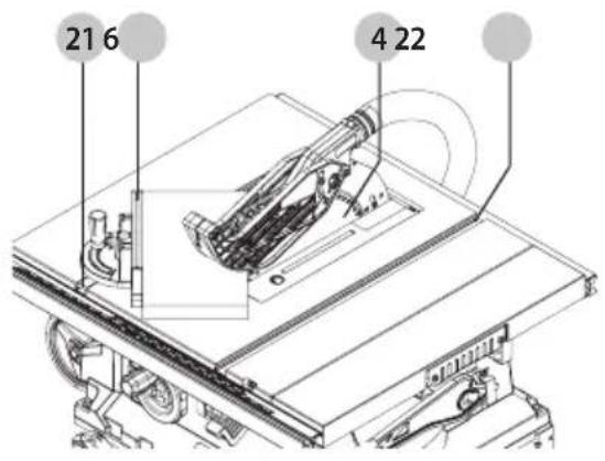
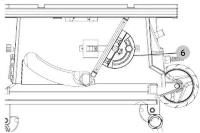
Auxiliary Tools Storage (Fig. S, T)
Auxiliary tools can be stored on the machine. The miter gauge 6 could be put on hook as Fig. S shows. The blade guard 2 and push stick 19 could be put on hook as Fig. T shows.
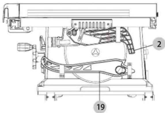
Blade Jamming Handling (Fig. U)
- Ensure the machine is disconnected from the power source.
- Remove the workpiece at first. WARNING: Be careful of your hands not touching the saw blade.
- Press the overloaded protector 23 and connect the plug again, the machine can be resumed to work. (Fig. U)
Applications
- Make sure the kerf is made on the scrap side of the measuring line.
- Cut the wood with the finished side up.
• Always have a proper support for the wood as it comes out of the blade.
• Make a test cut for important cuts. - Always use the correct blade depth setting. The top of the blade teeth should clear the top of the material being cut by 3 mm to 6 mm.
- Inspect the work-piece for knots or nails before beginning a cut. Remove any loose knots with a hammer.
• Always use clean, sharp, properly-set blades. Never make a cut with a dull blade. - When making a cut, use steady, even pressure. Never force a cut.
• DO NOT cut wet or warped lumber.
• Always hold your work-piece firmly with both hands or use a push stick.
MAINTENANCE
Your power tool has been designed to operate over a long period of time with a minimum of maintenance. Continuous satisfactory operation depends upon proper tool care and regular cleaning.
WARNING: To reduce the risk of serious personal injury, turn tool off and disconnect tool from power source before making any adjustments or removing/installing attachments or accessories. An accidental start-up can cause injury.
Remove the plug from the socket before carrying out any adjustment, servicing or maintenance. Keep tools sharp and clean for better and safer performane. Inspect tool cords periodically and if damaged, have repaired by an authorized service facility. Your power tool requires no additional lubrication or maintenance. There are no user serviceable parts in your power tool. Never use water or chemical cleaners to
clean your power tool. Wipe clean with a dry cloth. Always store your power tool in a dry place. Keep the motor ventilation slots clean. Keep all working controls free of dust. If you see some sparks flashing in the ventilation slots, this is normal and will not damage your power tool. If the supply cord is damaged, it must be replaced by the manufacturer, its service agent or similarly qualified persons in order to avoid a hazard.
Dust Extraction
Dust from materials such as lead-containing coatings and some wood types, can be harmful to one's health. Breathing-in the dust can cause allergic reactions and/or lead to respiratory infections of the user or bystanders. Certain dust, such as oak or beech dust, is considered carcinogenic, especially in connection with woodtreatment additives.
Observe the relevant regulations in your country for the materials to be worked.
The vacuum cleaner must be suitable for the material being worked.
When vacuuming dry dust that is especially detrimental to health or carcinogenic, use dust class M vacuum cleaner.
The machine is provided with a dust collection port at the rear of the machine suitable for use with dust extraction equipment featuring 35 mm nozzles. The blade guard assembly also features a dust collection port for 35 mm nozzles.
- During all operations, connect a dust extraction device designed in accordance with the relevant regulations regarding dust emission.
- Ensure that the dust extraction hose in use is suitable for the application and material being cut. Ensure proper hose management.
- A splitter accessory is available to connect both ports to a single dust extractor.
- Be aware that man-made materials such as chipboard or MDF produce more dust particles during cutting than natural timber.

Lubrication
Your power tool requires no additional lubrication.
Cleaning (Fig. A)
WARNING: Blow dirt and dust out of the main housing is dry air as often as dirt is seen collecting in and around the air vents. Wear approved eye protection and approved dust mask when performing this procedure.
WARNING: Never use solvents or other harsh chemicals for cleaning the non-metallic parts of the tool. These chemicals may weaken the materials used in these parts. Use a cloth dampened only with water and mild soap. Never let any liquid get inside the tool; never immerse any part of the tool into a liquid.
WARNING: To reduce the risk of injury, regularly clean the top and ventilation slots.
WARNING: To reduce the risk of injury, regularly clean the dust collection system.
WARNING: To reduce the risk of serious personal injury, do not reduce the saw without reattaching the dust access door.
The blade guard 2 and throat plate must be placed in position before operating the saw.
Before use, carefully inspect upper and lower blade guards as well as the dust extraction tube to determine that it will operate properly. Ensure that chips, dust or work piece particles cannot lead to blockage of one of the functions.
In case workpiece fragments are jammed between saw blade and guards, disconnect the machine from the power supply and follow the instructions given in Saw blade Assembly/Replacement. Remove the jammed parts and reassemble the saw blade.
Keep the ventilation slots clear and regularly clean the housing with a soft cloth.
Regularly clean the dust collection system.
Optional Accessories
WARNING: Since accessories, other than those offered by STANLEY, have not been tested with this product, use of such accessories with this tool could be hazardous. To reduce the risk of injury, only STANLEY recommended accessories should be used with this product.
Consult your dealer for further information on the appropriate accessories.
Replace the blade guard or carbon brush when worn. Contact your local Stanley service centre for details on a blade guard or carbon brush replacement.
Protecting the Environment
Separate collection. Products marked with this symbol must not be disposed of with normal household waste. Products contain materials that can be recovered or recycled reducing the demand for raw materials.
Please recycle electrical products according to local provisions.
Further information is available at www.2helpU.com.
SIERRA DE MESA
SST1800
¡Enhorabuena!
Director – Outdoor Products Group
STANLEY Europe, Egide Walschaertsstraat14-18,
WAARSCHUWING: Lees alle
BEWAAR ALLE WAARSCHUWINGEN EN INSTRUCTIES ALS TOEKOMSTIG REFERENTIEMATERIAA
Director – Outdoor Products Group
STANLEY Europe, Egide Walschaertsstraat14-18, 2800 Mechelen, Belgia
03.08.2021

ADVARSEL: For å redusere skaderisikoen, les bruksanvisningen.
2) Advarsler for saging
a)

Director – Outdoor Products Group
STANLEY Europe, Egide Walschaertsstraat14-18,
2800 Mechelen, Belgia
03.08.2021

Director – Outdoor Products Group
STANLEY Europe, Egide Walschaertsstraat14-18,
2800 Mechelen, Belgien
03.08.2021