
SFMCS701 - Saw STANLEY - Free user manual and instructions
Find the device manual for free SFMCS701 STANLEY in PDF.
| Product type | Cordless Sliding Compound Miter Saw |
| Brand | STANLEY |
| Model | SFMCS701 |
| Rated voltage | 18 V (Li-Ion battery) |
| No-load speed | 3800 rpm |
| Blade diameter | 190 mm |
| Arbor | 16 mm |
| Cutting capacity (0° horizontal miter) | 50 x 216 mm |
| Cutting capacity (0° vertical miter) | 90 x 15 mm |
| Miter range | 47° left / 47° right |
| Bevel range | From 0° to 47° left |
| Weight (without battery) | 10 kg |
| Compatible battery type | STANLEY FATMAX Li-Ion (SFMCB201, 202, 204, 206) |
| Charger type | SFMCB11, SFMCB12, SFMCB14 (230 V AC) |
| Sound pressure level (LpA) | 83.0 dB(A) (uncertainty K=3 dB) |
| Sound power level (LWA) | 94.5 dB(A) |
| Guidance system | Blade shadow guide |
| Blade brake | Automatic electric (stop < 5 s) |
| Compatible materials | Wood, plastic, non-ferrous metals |
| Maintenance and cleaning | Regularly clean the table and rails; do not use solvents on the protective guard |
| Spare parts and repairability | Have repairs done only by an STANLEY FATMAX authorized service center; use original parts |
| Warranty | 12 months |
Frequently Asked Questions - SFMCS701 STANLEY
User questions about SFMCS701 STANLEY
0 question about this device. Answer the ones you know or ask your own.
Ask a new question about this device
Download the instructions for your Saw in PDF format for free! Find your manual SFMCS701 - STANLEY and take your electronic device back in hand. On this page are published all the documents necessary for the use of your device. SFMCS701 by STANLEY.
USER MANUAL SFMCS701 STANLEY
Your STANLEY FATMAX SFMCS701 sliding compound mitresaw has been designed for sawing wood, plastic and nonferrous metal only. This tool is intended for professional and private, non professional users.
Safety instructions
General power tool safety warnings

Warning! Read all safety warnings, instructions, illustrations and specifications provided with power tool. Failure to follow the warnings and instructions listed below may result in electric shock, fire and/or serious injur
Save all warnings and instructions for future reference.
The term "power tool" in all of the warnings listed below refers to your mains operated (corded) power tool or battery operated (cordless) power tool.
1. Work area safety
a. Keep work area clean and well lit. Cluttered or dark areas invite accidents.
b. Do not operate power tools in explosive atmospheres, such as in the presence of flammable liquids, gases or dust. Power tools create sparks which may ignite the dust or fumes.
c. Keep children and bystanders away while operating a power tool. Distractions can cause you to lose control.
2. Electrical safety
a. Power tool plugs must match the outlet. Never modify the plug in any way. Do not use any adapter plugs with earthed (grounded) power tools. Unmodified plugs and matching outlets will reduce risk of electric shock.
b. Avoid body contact with earthed or grounded surfaces such as pipes, radiators, ranges and refrigerators. There is an increased risk of electric shock if your body is earthed or grounded.
c. Do not expose power tools to rain or wet conditions. Water entering a power tool will increase the risk of electric shock.
d. Do not abuse the cord. Never use the cord for carrying, pulling or unplugging the power tool. Keep cord away from heat, oil, sharp edges or moving parts. Damaged or entangled cords increase the risk of electric shock.
e. When operating a power tool outdoors, use an extension cord suitable for outdoor use. Use of a cord suitable for outdoor use reduces the risk of electric shock.
f. If operating a power tool in a damp location is unavoidable, use a residual current device (RCD) protected supply. Use of an RCD reduces the risk of electric shock.
3. Personal safety
a. Stay alert, watch what you are doing and use common sense when operating a power tool. Do not use a power tool while you are tired or under the influence of drugs, alcohol or medication. A moment of inattention while operating power tools may result in serious personal injury.
b. Use personal protective equipment. Always wear eye protection. Protective equipment such as dust mask, non-skid safety shoes, hard hat, or hearing protection used for appropriate conditions will reduce personal injuries.
c. Prevent unintentional starting. Ensure the switch is in the off-position before connecting to power source and/or battery pack, picking up or carrying the tool. Carrying power tools with your finger on the switch or energising power tools that have the switch on invites accidents.
d. Remove any adjusting key or wrench before turning the power tool on. A wrench or a key left attached to a rotating part of the power tool may result in personal injury.
e. Do not overreach. Keep proper footing and balance at all times. This enables better control of the power tool in unexpected situations.
f. Dress properly. Do not wear loose clothing or jewellery. Keep your hair, clothing and gloves away from moving parts. Loose clothes, jewellery or long hair can be caught in moving parts.
g. If devices are provided for the connection of dust extraction and collection facilities, ensure these are connected and properly used. Use of dust collection can reduce dust-related hazards.
h. Do not let familiarity gained from frequent use of tools allow you to become complacent and ignore tool safety principles. A careless action can cause severe injury within a fraction of a second.
4. Power tool use and care
a. Do not force the power tool. Use the correct power tool for your application. The correct power tool will do the job better and safer at the rate for which it was designed.
b. Do not use the power tool if the switch does not turn it on and off. Any power tool that cannot be controlled with the switch is dangerous and must be repaired.
c. Disconnect the plug from the power source and/or the battery pack from the power tool before making any adjustments, changing accessories, or storing power tools. Such preventive safety measures reduce the risk of starting the power tool accidentally.
d. Store idle power tools out of the reach of children and do not allow persons unfamiliar with the power tool or these instructions to operate the power tool. Power tools are dangerous in the hands of untrained users.
e. Maintain power tools and accessories. Check for misalignment or binding of moving parts, breakage of parts and any other condition that may affect the power tools operation. If damaged, have the power tool repaired before use. Many accidents are caused by poorly maintained power tools.
f. Keep cutting tools sharp and clean. Properly maintained cutting tools with sharp cutting edges are less likely to bind and are easier to control.
g. Use the power tool, accessories and tool bits etc. in accordance with these instructions, taking into account the working conditions and the work to be performed. Use of the power tool for operations different from those intended could result in a hazardous situation.
h. Keep handles and grasping surfaces dry, clean and free from oil and grease. Slippery handles and greasy surfaces do not allow for safe handling and control of the tool in unexpected situations.
5. Battery tool use and care
a. Recharge only with the charger specified by the manufacturer. A charger that is suitable for one type of battery pack may create a risk of fire when used with another battery pack.
b. Use power tools only with specifically designated battery packs. Use of any other battery packs may create a risk of injury and fire.
c. When battery pack is not in use, keep it away from other metal objects, like paper clips, coins, keys, nails, screws, or other small metal objects, that can make a connection from one terminal to another.
Shorting the battery terminals together may cause burns or a fire.
d. Under abusive conditions, liquid may be ejected from the battery; avoid contact. If contact accidentally occurs, flush with water. If liquid contacts eyes, additionally seek medical help. Liquid ejected from the battery may cause irritation or burns.
e. Do not use a battery pack or tool that is damaged or modified. Damaged or modified batteries may exhibit unpredictable behaviour resulting in fire, explosion or risk of injury.
f. Do not expose a battery pack or tool to fire or excessive temperature. Exposure to fire or temperature above 130^ may cause explosion.
g. Follow all charging instructions and do not charge the battery pack or tool outside the temperature range specified in the instructions. Charging improperly or at temperatures outside the specified range may damage the battery and increase the risk of fire.
- Service
a. Have your power tool serviced by a qualified repair person using only identical replacement parts. This will ensure that the safety of the power tool is maintained.
b. Never service damaged battery packs. Service of battery packs should only be performed by the manufacturer or authorised service providers.
Safety instructions for metre saws
Mitre saws are intended to cut wood or wood-like products, they cannot be used with abrasive cut-off wheels for cutting ferrous material such as bars, rods, studs, etc. Abrasive dust causes moving parts such as the lower guard to jam. Sparkts from abrasive cutting will burn the lower guard, the kerf insert and other plastic parts.
Use clamps to support the workpiece whenever possible. If supporting the workpiece by hand, you must always keep your hand at least 100~mm from either side of the saw blade. Do not use this saw to cut pieces that are too small to be securely clamped or held by hand. If your hand is placed too close to the saw blade, there is an increased risk of injury from blade contact.
The workpiece must be stationary and clamped or held against both the fence and the table. Do not feed the workpiece into the blade or cut "freehand" in any way. Unrestrained or moving workpieces could be thrown at high speeds, causing injury.
Push the saw through the workpiece. Do not pull the saw through the workpiece.
ENGLISH
(Original instructions)
To make a cut, raise the saw head and pull it out over the workpiece without cutting, start the motor, press the saw head down and push the saw through the workpiece. Cutting on the pull stroke is likely to cause the saw blade to climb on top of the workpiece and violently throw the blade assembly towards the operator.
Never cross your hand over the intended line of cutting either in front or behind the saw blade. Supporting the workpiece "cross handed" i.e. holding the workpiece to the right of the saw blade with your left hand or vice versa is very dangerous.
Do not reach behind the fence with either hand closer than 100~mm from either side of the saw blade, to remove wood scraps, or for any other reason while the blade is spinning. The proximity of the spinning saw blade to your hand may not be obvious and you may be seriously injured.
Inspect your workpiece before cutting. If the workpiece is bowed or warped, clamp it with the outside bowed face toward the fence. Always make certain that there is no gap between the workpiece, fence and table along the line of the cut. Bent or warped workpieces can twist or shift and may cause binding on the spinning saw blade while cutting. There should be no nails or foreign objects in the workpiece.
Do not use the saw until the table is clear of all tools, wood scraps, etc., except for the workpiece. Small debris or loose pieces of wood or other objects that contact the revolving blade can be thrown with high speed.
Cut only one workpiece at a time. Stacked multiple workpieces cannot be adequately clamped or braced and may bind on the blade or shift during cutting.
Ensure the litre saw is mounted or placed on a level, firm work surface before use. A level and firm work surface reduces the risk of the litre saw becoming unstable.
Plan your work. Every time you change the bevel or metre angle setting, make sure the adjustable fence is set correctly to support the workpiece and will not interfere with the blade or the guarding system. Without turning the tool "ON" and with no workpiece on the table, move the saw blade through a complete simulated cut to assure there will be no interference or danger of cutting the fence.
Provide adequate support such as table extensions, saw horses, etc. for a workpiece that is wider or longer than the table top. Workpieces longer or wider than the metre saw table can tip if not securely supported. If the cut-off piece or workpiece tips, it can lift the lower guard or be thrown by the spinning blade.
Do not use another person as a substitute for a table extension or as additional support.
Unstable support for the workpiece can cause the blade to bind or the workpiece to shift during the cutting operation pulling you and the helper into the spinning blade.
The cut-off piece must not be jammed or pressed by any means against the spinning saw blade. If confined, i.e. using length stops, the cut-off piece could get wedged against the blade and thrown violently.
Always use a clamp or a fixture designed to properly support round material such as rods or tubing. Rods have a tendency to roll while being cut, causing the blade to "bite" and pull the work with your hand into the blade.
Let the blade reach full speed before contacting the workpiece. This will reduce the risk of the workpiece being thrown.
If the workpiece or blade becomes jammed, turn the mitre saw off. Wait for all moving parts to stop and disconnect the plug from the power source and/or remove the battery pack. Then work to free the jammed material. Continued sawing with a jammed workpiece could cause loss of control or damage to the mitre saw.
After finishing the cut, release the switch, hold the saw head down and wait for the blade to stop before removing the cut-off piece. Reaching with your hand near the coasting blade is dangerous.
Additional safety instructions for litre saws
The intended use is described in this instruction manual. The use of any accessory or attachment or performance of any operation with this tool other than those recommended in this instruction manual may present a risk of personal injury and/or damage to property.
Do not use cracked/bent/damaged/deformed saw blades.
Replace the kerf plate when worn.
Do not use blades of larger or smaller diameter than recommended. For the proper blade rating refer to the technical data. Use only the blades specified in this manual, complying with EN 847-1.
Do not use High Speed Steel (HSS) saw blades.

Warning! Contact with or inhalation of dusts arising from sawing applications may endanger the health of the operator and possible bystanders. Wear a dust mask specifically designed for protection against dust and fumes and ensure that persons within or entering the work area are also protected.
Do not work with material containing asbestos. Asbestos is considered to be carcinogenic.
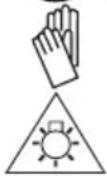
Wear gloves when handling saw blades and rough material (saw blades should be carried in a holder when practicable).
Wear hearing protection to reduce the risk of induced hearing loss.
Consider using specially designed noise-reduction blades.
Wear eye protection to reduce the risk of personal injury.
Use the dust bag provided when sawing wood.
Hold power tool by insulated gripping surfaces when performing an operation where the cutting accessory may contact hidden wiring or its own cord. Cutting accessory contacting a "live" wire may make exposed metal parts of the power tool "live" and could give the operator an electric shock
Select the correct blade for the material to be cut.
Do not operate the machine without the guard in position. Do not operate the machine if the guard does not function or is not maintained properly.
Ensure that the arm is securely fixed when performing bevel cuts.
Before each cut ensure that the machine is stable.
Keep handles dry, clean and free from oil and grease.
Keep the surrounding area of the machine well maintained and free of loose materials, e.g. chips and off-cuts.
Ensure the machine and the work area are provided with adequate general or localised lighting.
Do not allow untrained people to operate this machine.
Ensure that the blade is mounted correctly before use. Make sure that the blade rotates in the correct direction. Keep the blade sharp. Follow instruction for lubricating and changing accessories.
Ensure the speed marked on the saw blade is at least equal to the speed marked on the saw.
Ensure that any spacers and spindle rings used are suitable for the purpose as stated by STANLEY FATMAX.
Repairs to the cut line guidance system should be carried out by authorised repair agents or STANLEY FATMAX service staff.
Remove the battery from the machine before carrying out any maintenance or when changing the blade.
- Never perform any cleaning, maintenance, removal of any off-cuts or other parts of the work piece form the cutting area when the machine is running and the saw head is not in the rest position.
When possible, always mount the machine to a bench.
Make sure all locking knobs and handles are tight before starting any operation.
Never use your saw without the table insert.
- Never attempt to stop the machine in motion rapidly by jamming a tool or other means against the blade; serious accidents can be caused unintentionally in this way.
Before using or fitting any accessory consult the instruction manual. The improper use of an accessory can cause damage.
Raise the blade from the table insert in the work piece prior to releasing the on/of switch.
Do not wedge anything against the fan to hold the motor shaft.
The blade guard on your saw will automatically raise when the arm is brought down; it will lower over the blade when the arm is raised. The guard can be raised by hand when installing or removing saw blades or for inspection of the saw. Never raise the blade guard manually unless the machine is switched off.
- Check periodically that the motor air slots are clean and free of chips.
Never make the warning signs on the power tool unrecognisable.
- Never stand on the power tool. Serious injuries could occur when the power tool tips over or when coming in contact with the saw blade.
Do not take hold of the saw blade after working before it has cooled. The saw blade becomes very hot while working.
To avoid injury from materials being thrown, remove the battery from saw to avoid accidental starting, and then remove small materials.
Before use and after any maintenance the blade guard must be checked to ensure proper function. This test must be performed with the saw switched off and the battery removed. The arm must be raised and lowered to ensure the guard covers the blade and the blade does not contact the guard. If the guard fails to operate correctly, have your power tool serviced by a qualified repair agent. Call STANLEY FATMAX customer services for you nearest service agent.
This litre saw has been designed for sawing wood, plastic and nonferrous metal only. Do not use the saw to cut other materials than those recommended by the manufacturer.
Do not take hold of the saw blade after working before it has cooled. The saw blade becomes very hot while working.

Warning! Cutting plastics, sap coated wood, and other materials may cause melted material to accumulate on the blade tips and the body of the saw blade, increasing the risk of the blade overheating and binding while cutting.
Safety of others
This charger can be used by children aged from 8 years and above and persons with reduced physical, sensory or mental capabilities or lack of experience and knowledge if they have been given supervision or instruction concerning use of the appliance in a safe way and understand the hazards involved.
Children shall not play with the appliance. Cleaning and user maintenance shall not be made by children without supervision.
ENGLISH
(Original instructions)
Residual risks
The following risks are inherent to the use of saws:
Even with the application of the relevant safety regulations and the implementation of safety devices, certain residual risks can not be avoided. These include:
Injuries caused by touching any rotating/moving parts.
Impairment of hearing.
Risk of accidents caused by the uncovered parts of the rotating saw blade.
Risk of injury when changing any parts, blades or accessories.
Risk of squeezing fingers when opening the guards.
Health hazards caused by breathing dust developed when sawing wood, especially oak, beech and MDF.
Injuries caused by prolonged use of a tool. When using any tool for prolonged periods ensure you take regular breaks.
Noise
The declared noise emission values have beenmeasured in accordance with a standard test method and may be used for comparing one tool with another.
The declared noise emission values may also be used in a preliminary assessment of exposure.
Warning! The noise emissions during actual use of the power tool can differ from the declared values depending on the ways in which the tool is used especially what kind of workpiece is processed.
Warning! Always wear proper personal hearing protection. Under some conditions and duration of use, noise from this product may contribute to hearing loss. Be aware of the following factors influencing exposure to noise:
Use saw blades designed to reduce the emitted noise,
Use only well sharpened saw blades, and
Use specifically designed noise-reduction saw blades.
Labels on tool
The following pictograms along with the date code are shown on the tool:


Warning! To reduce the risk of injury, the user must read the instruction manual.
Wear safety glasses or goggles
Wear ear protection
Wear a dust mask
This product is not to be used by children under 16

Keep hands away from blade
No Hands Zone - Keep fingers and arms away from rotational saw blades
Wear gloves when handling saw blades
Do not stare at operating lamp
Additional safety instructions for batteries and chargers
Warning! The appliance is only to be used with the power supply unit provided with the appliance.
Note: The tool's operating temperature range is recommended at 4^ to 40^ .
Batteries
Never attempt to open for any reason.
Do not expose the battery to water.
Do not store in locations where the temperature may exceed 40^
Charge only at ambient temperatures between 10^ and 40^ .
Charge only using the charger provided with the tool.
When disposing of batteries, follow the instructions given in the section "Protecting the environment".

Do not attempt to charge damaged batteries.
Chargers
Use your Stanley FatMax charger only to charge the battery in the tool with which it was supplied. Other batteries could burst, causing personal injury and damage.
Never attempt to charge non-rechargeable batteries.
Have defective cords replaced immediately.
Do not expose the charger to water.
Do not open the charger.
Do not probe the charger.

The charger is intended for indoor use only.

Read the instruction manual before use.
Electrical safety

Your charger is double insulated; therefore no earth wire is required. Always check that the mains voltage corresponds to the voltage on the rating plate. Never attempt to replace the charger unit with a regular mains plug.
- If the supply cord is damaged, it must be replaced by the manufacturer or an authorised Stanley FatMax Service Centre in order to avoid a hazard.
Features
This tool includes some or all of the following features.
- Trigger switch
- Operating handle
- Mounting holes
- Lower Guard
- Mitre locking knob
- Mitre latch button
- Kerf plate
- Mitre scale
- Mitre scale indicator
- Carry grips
- Fence
- Bevel lock knob
- Rails
13a.Velcro strap
- Dust port
- Battery pack
- Work light switch
- Lock off lever
- Rail lock screw
- Clamp mounting hole
- Lock down pin
Assembly (Fig. A)
Your litre saw is part assembled in the carton.
Open the box and lift the saw out by using the carry grips (10) in the base of the saw (Fig. A).
Place the saw on a smooth, flat surface such as a workbench or strong table.
Examine Assembly diagram on page 2 of this manual to become familiar with the saw and its various parts. The section on adjustments will refer to these terms and you must know what and where the parts are.
The mitre locking knob (5) is not assembled for shipping. Remove the mitre locking knob (5) from the packaging and screw onto the saw, see figure G and J for position.
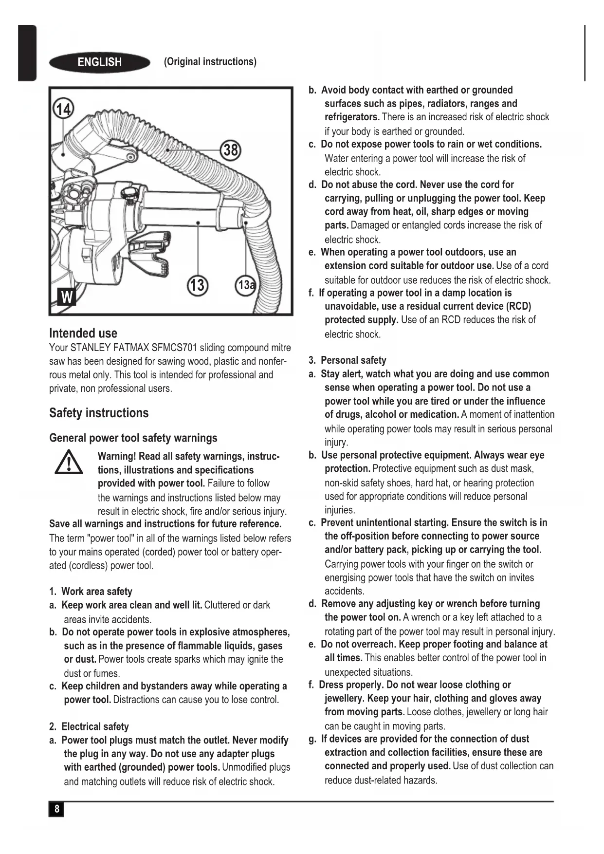
- Your saw has a built-in dust port (14) that allows either the supplied, but not assembled, dust bag (35) or shop vacuum system to be connected (Fig. N).
Kerf plate (Fig. J)
The kerf plate (7) is mounted to the table by 6 screws. The kerf plate (7) height is not adjustable.
Note: If the kerf plate (7) is worn, damaged or needs to be replaced, repairs should be carried out by authorised repair agents or STANLEY FATMAX service staff.
Lock down pin (Fig. F)
Warning! The lock down pin should be used ONLY when carrying or storing the saw. NEVER use the lock down pin for any cutting operation.
Note: To lift, carry and support the litre saw during transport use the two carrying handles (10) located on both sides of the litre saw base (Fig. A).
To lock the saw head in the down position, push the saw head down, push the lock down pin (20) in and release the saw head. This will hold the saw head safely down for transporting the saw from place to place. To release, press the saw head down and pull the pin out.
Warning! Always be sure that the tool is switched off and the battery is removed from the tool before adjusting or checking the tools function.
Charging a battery (fig. B)
The battery needs to be charged before first use and whenever it fails to produce sufficient power on jobs that were easily done before.
The battery may become warm while charging; this is normal and does not indicate a problem.
Warning! Do not charge the battery at ambient temperatures below 10^ or above 40^ . Recommended charging temperature: approx. 24^ .
Note: The charger will not charge a battery if the cell temperature is below approximately 10^ or above 40^ .
The battery should be left in the charger and the charger will begin to charge automatically when the cell temperature warms up or cools down.
Note: To ensure maximum performance and life of lithium-ion battery packs, charge the battery pack fully before first use.
Plug the charger (21) into an appropriate outlet before inserting battery pack (15).
- The green charging light (21a) will blink continuously indicating that the charging process has started.
- The completion of charge will be indicated by the green charging light (21a) remaining ON continuously. The battery pack (15) is fully charged and may be removed and used at this time or left in the charger (21).
Charge discharged batteries within 1 week. Battery life will be greatly diminished if stored in a discharged state.
Charger LED Modes
| Charging: Green LED Intermittent |

Fully Charged:
Green LED Solid

Hot/Cold Pack Delay:
Green LED Intermittent
Red LED Solid

Note: The compatible charger(s) will not charge a faulty battery pack. The charger will indicate a faulty battery pack by refusing to light.
Note: This could also mean a problem with a charger. If the charger indicates a problem, take the charger and battery pack to be tested at an authorized service centre.
Leaving the battery in the charger
The charger and battery pack can be left connected with the LED glowing indefinitely. The charger will keep the battery pack fresh and fully charged.
Hot/Cold Pack Delay
When the charger detects a battery that is too hot or too cold, it automatically starts a Hot/Cold Pack Delay, the green LED (21a) will flash intermittently, while the red LED (21b) will remain on continuously, suspending charging until the battery has reached an appropriate temperature. The charger then automatically switches to the pack charging mode. This feature ensures maximum battery life.
Battery state of charge indicator (Fig. C)
The battery includes a state of charge indicator to quickly determine the extent of battery life as shown in figure B. By pressing the state of charge button (15a) you can easily view the charge remaining in the battery as illustrated in figure C.

Fitting and removing the battery (fig. D, E)
To fit the battery (15), line it up with the receptacle on the tool (22). Slide the battery into the receptacle and push until the battery snaps into place.
To remove the battery, push the battery release button (15b) while at the same time pulling the battery out of the receptacle as shown in figure E.
Changing or Installing a New Saw Blade (Fig. G, H, I)
Warning! To reduce the risk of serious personal injury, turn tool off and remove the battery pack before transporting, making any adjustments or removing/installing attachments or accessories. An accidental start-up can cause injury.
Removing the Blade
Remove battery pack (15) from the saw.
Raise the arm to the upper position and raise the lower guard (4) as far as possible.
Loosen, but do not remove the guard bracket front screw (24) until the bracket (25) can be raised far enough to access the blade screw (26). Lower guard will remain raised due to the position of the guard bracket screw.
Depress the spindle lock button (28) while carefully rotating the saw blade (29) by hand until the lock engages.
Keeping the button depressed, use the other hand and the hex side of the wrench provided to loosen the blade screw (26). (Turn clockwise, left-hand threads.)
Remove the blade screw (26) using the hex side of the wrench provided, the outer clamp washer (30) and blade (29). The inner clamp washer (31) may be left on the spindle (32).
Installing a Blade
Remove battery pack (15) from the saw.
With the arm raised, the lower guard (4) held open and the guard bracket (25) raised, place the blade (29) on the spindle (32) and against the inner blade clamp (31) with the teeth on the blade pointing in the direction of rotation as marked on the saw.
Assemble the outer clamp washer (30) onto the spindle (32).
Install the blade screw (26) and, engaging the spindle lock (28), tighten the screw (26) firmly with wrench provided (turn counterclockwise, left-hand threads).
Return the guard bracket (25) to its original full down position and firmly tighten the guard bracket screw (24) to hold bracket in place.
Cut line guidance system
Warning! Do not stare into work light. Serious eye injury could result.
Note: The battery must be charged and connected to the litre saw.
The cut line guidance system can only be turned On or Off by the work light switch (16).
To cut through an existing pencil line on a piece of wood, turn on the cut line guidance system using the work light switch (16) (not with the main trigger), then pull down on the operating handle (2) to bring the saw blade close to the wood.
The shadow of the blade will appear on the wood. This shadow line represents the material that the blade will remove when performing a cut.
To correctly locate your cut to the pencil line, align the pencil line with the edge of the blade's shadow. Keep in mind that you may have to adjust the metre or bevel angles in order to match the pencil line exactly.
Your saw is equipped with a battery fault feature. The work light begins to flash when the battery is near the end of its useful charge, or when the battery is too hot. Charge the battery prior to continuing cutting applications. Refer to charging procedure under Important safety instructions for battery packs for battery charging instructions.
Mitre control (Fig. J)
The metre lock knob (5) and metre latch button (6) allow you to metre your saw to 47^ right and 47^ left. The metre latch will automatically locate at 0^ , 15^ , 22.5^ , 31.6^ and 45^ both left and right. To metre the saw, unlock the metre lock mechanism by turning the metre lock knob (5) anti clockwise to unlock and clockwise to lock. Pull the metre latch button (6) up, and set the metre angle desired on the metre scale (8). Lock the metre lock knob (5) by turning clockwise.
Bevel Lock Knob (Fig. K)
The bevel lock allows you to bevel the saw 48^ to the left. To adjust the bevel setting, turn the bevel lock knob (12) counterclockwise to loosen. To tighten, turn the bevel lock knob clockwise.
Caution! Pinch hazard. Be sure to tighten bevel lock knob before adjusting overrides.
Trigger Switch (Fig. L)
To turn the saw on, push the lock-off lever (17) to the left, then depress the trigger switch (1). The saw will run while the switch is depressed. Allow the blade to spin up to full operating speed before making the cut. To turn the saw off, release the switch. Allow the blade to stop before raising the saw head. There is no provision for locking the switch on. A hole (1a) is provided in the trigger for insertion of a padlock to lock the switch off.
Your saw is not equipped with an automatic electric blade brake, but the saw blade should stop within 5 seconds of trigger release. This is not adjustable. If the stop time repeatedly exceeds 5 seconds, have the tool serviced by an authorised Stanley FatMax service centre.
Always be sure the blade has stopped before removing it from the kerf.
Dust Extraction (Fig. M)
Warning! To reduce the risk of serious personal injury, turn tool off and remove the battery pack before transporting, making any adjustments or removing/installing attachments or accessories. An accidental start-up can cause injury. Your saw has a built-in dust port (14) that allows either the supplied dust bag (35) or a shop vacuum system to be connected.
To attach the dust bag
Fit the dust bag (35) to the dust port (14) as shown in Figure M.
A vacuum tube (38 - not provided) can be fitted to the dust port (14) rather than the dust bag (35). This can be done by fitting your vacuum tube (38) in place of the dust bag (35), see figure M.
Use the velcro strap (13a) to hold your vacuum tube (38) clear from the sliding rails (13) whilst operating the saw.
Note: The velcro strap (13a) is not a carrying handle and should not be used to move or transport the saw.
To empty the dust bag
Remove dust bag (35) from the saw and gently shake or tap the dust bag to empty.
Reattach the dust bag back onto the dust port (14).
You may notice that all the dust will not come free from the bag. This will not affect cutting performance but will reduce the saw's dust collection efficiency. To restore your saw's dust collection efficiency, depress the spring inside the dust bag when you are emptying it and tap it on the side of the trash can or dust receptacle.
Warning! Never operate this saw unless the dust bag is in place. Wood dust may create a breathing hazard.
Cutting with your saw
If the slide feature is not used, ensure the saw head is pushed back as far as possible and the rail lock screw (18) is tightened. This will prevent the saw from sliding along its rails as the workpiece is engaged.
Note: DO NOT CUT FERROUS METALS OR MASONRY WITH THIS SAW (NON FERROUS METALS CAN BE CUT BY THIS SAW. Do not use any abrasive blades.
Note: Refer to guard actuation and visibility in the adjustments section for important information about the lower guard before cutting.
Crosscuts (fig. N)
A crosscut is made by cutting wood across the grain at any angle. A straight crosscut is made with the metre arm at the zero degree position. Set and lock the metre arm at zero, hold the wood firmly on the table and against the fence. With the rail lock screw (18) tightened, turn on the saw by squeezing the trigger switch (1).
When the saw comes up to speed (about 1 second) lower the arm smoothly and slowly to cut through the wood. Let the blade come to a full stop before raising arm.
When cutting anything larger than a 2 × 4 (51 x 102), use an out-down-back motion with the rail lock screw (18) loosened. Pull the saw out, toward you, lower the saw head down toward the work piece, and slowly push the saw back to complete the cut. Do not allow the saw blade to contact the top of the work piece while pulling out. The saw may run toward you, possibly causing personal injury or damage to the work piece.
ENGLISH
(Original instructions)
Warning! Always use a work clamp to maintain control and reduce the risk of work piece damage and personal injury, if your hands are required to be within 6^ (152 mm) of the blade during the cut.
Note! The rail lock screw (18) must be loose to allow the saw to slide along its rails.
Mitre crosscuts are made with the litre arm at some angle other than zero.
This angle is often 45^ for making corners, but can be set anywhere from zero to 47^ left or 47^ right. Make the cut as described above.
When performing a metre cut on work pieces wider than a 2 x 6 that are shorter in length, always place the longer side against the fence (Fig. O).
To cut through an existing pencil line on a piece of wood, match the angle as close as possible. Cut the wood a little too long and measure from the pencil line to the cut edge to determine which direction to adjust the metre angle and recut. This will take some practice, but it is a commonly used technique.
Bevel cuts
A bevel cut is a crosscut made with the saw blade leaning at an angle to the wood. In order to set the bevel, loosen the bevel lock knob (12), and move the saw to the left as desired. Once the desired bevel angle has been set, tighten the bevel lock firmly. Bevel angles can be set from 3^ right to 48^ left.
Quality of cut
The smoothness of any cut depends on a number of variables. Things like material being cut, blade type, blade sharpness and rate of cut all contribute to the quality of the cut. When smoothest cuts are desired for moulding and other precision work, a sharp (60 tooth carbide tip) blade and a slower, even cutting rate will produce the desired results.
Ensure that the material does not move or creep while cutting; clamp it securely in place.
Always let the blade come to a full stop before raising arm. If small fibres of wood still split out at the rear of the work piece, stick a piece of masking tape on the wood where the cut will be made. Saw through the tape and carefully remove tape when finished.
For varied cutting applications, refer to the list of recommended saw blades for your saw and select the one that best fits your needs. Refer to Saw Blades under Optional Accessories.
Body and hand position (fig. O1-O4)
Proper positioning of your body and hands when operating the litre saw will make cutting easier, more accurate and safer. Never place hands near cutting area. Place hands no closer than 6^ (152 mm) from the blade. Hold the work piece tightly to the table and the fence when cutting. Keep hands in position until the trigger has been released and the blade has completely stopped.
ALWAYS MAKE DRY RUNS (UN-POWERED) BEFORE FINISH CUTS SO THAT YOU CAN CHECK THE PATH OF THE BLADE. DO NOT CROSS HANDS, AS SHOWN IN FIGURE O3.
Keep both feet firmly on the floor and maintain proper balance. As you move the metre arm left and right, follow it and stand slightly to the side of the saw blade. Sight through the guard louvres when following a pencil line.
Clamping the work piece
Warning! To reduce the risk of serious personal injury, turn tool off and remove the battery pack before transporting, making any adjustments or removing/installing attachments or accessories. An accidental start-up can cause injury.
Warning! A work piece that is clamped, balanced and secure before a cut may become unbalanced after a cut is completed. An unbalanced load may tip the saw or anything the saw is attached to, such as a table or workbench. When making a cut that may become unbalanced, properly support the work piece and ensure the saw is firmly bolted to a stable surface. Personal injury may occur.
Warning! The clamp foot must remain clamped above the base of the saw whenever the clamp is used. Always clamp the work piece to the base of the saw – not to any other part of the work area. Ensure the clamp foot is not clamped on the edge of the base of the saw.
Warning! Always use a work clamp to maintain control and reduce the risk of work piece damage and personal injury, if your hands are required to be within 6'' (152 mm) of the blade during the cut. If you cannot secure the work piece on the table and against the fence by hand (irregular shape, etc.), or your hand would be less than 6'' (152 mm) from the blade, a clamp or other fixture must be used.
Use the material clamp provided with your saw. To purchase a material clamp, contact your local retailer or Stanley FatMax service centre.
- Other aids such as spring clamps, bar clamps or C-clamps may be appropriate for certain sizes and shapes of material. Use care in selecting and placing these clamps. Take time to make a dry run before making the cut.
To install clamp (fig. P)
Insert the clamp (37) into the hole (19) behind the fence. The clamp should be facing toward the back of the mitre saw. The groove on the clamp rod should be fully inserted into the base. Ensure this groove is fully inserted into the base of the mitre saw. If the groove is visible, the clamp will not be secure.
Rotate the clamp 180^ toward the front of the metre saw.
Loosen the knob to adjust the clamp up or down, then use the fine adjust knob to firmly clamp the work piece.
Note: Place the clamp on the opposite side of the base when bevelling. ALWAYS MAKE DRY RUNS (UN-POWERED) BEFORE FINISH CUTS TO CHECK THE PATH OF THE BLADE. ENSURE THE CLAMP DOES NOT INTERFERE WITH THE ACTION OF THE SAW OR GUARDS.
Adjustments
Your litre saw is fully and accurately adjusted at the factory at the time of manufacture. If readjustment due to shipping and handling or any other reason is required, follow the instructions below to adjust your saw.
Once made, these adjustments should remain accurate. Take a little time now to follow these directions carefully to maintain the accuracy of which your saw is capable.
Mitre scale adjustment (fig. Q1)
Lock the arm in the down position. Unlock the metre lock knob (5) and swing the metre arm until the metre latch button (6) locks it at the 0^ metre position. Do not lock the metre lock knob. Place a square against the saw's fence and blade, as shown. (Do not touch the tips of the blade teeth with the square. To do so will cause an inaccurate measurement.) If the saw blade is not exactly perpendicular to the fence, loosen and move the material fence until the blade is perpendicular to the fence, as measured with the square. Pay no attention to the reading of the metre pointer at this time.
Bevel square to table adjustment (Fig. Q2)
To align the blade square to the table, lock the arm in the down position with the lock down pin (20). Place a square against the blade, ensuring the square is not on top of a tooth. Loosen the bevel lock knob (5) and ensure the arm is firmly against the 0^ bevel stop. Rotate the 0^ bevel adjustment screw with the 1/2'' (12.7 mm) socket (not provided) as necessary so that the blade is at 0^ bevel to the table, as measured with the square.
Guard actuation and visibility (Fig. V)
Warning! Pinch hazard. To reduce the risk of injury, keep thumb underneath the operating handle when pulling the handle down. The lower guard will move up as the operating handle is pulled down, which could cause pinching.
The lower guard (4) on your saw has been designed to automatically uncover the blade when the arm is brought down and to cover the blade when the arm is raised.
Before each use or after making adjustments, cycle the arm (un-powered) and make sure the guard opens smoothly and closes fully. It should not contact the blade. With the arm up, raise the guard (un-powered) as shown in Figure V and release. The guard should fully close rapidly.
Do not operate the saw if the guard does not move freely and fully close rapidly. Never clamp or tie the guard in an open position when operating the saw.
The guard can be raised by hand when installing or removing saw blades or for inspection of the saw.
NEVER RAISE THE LOWER GUARD MANUALLY UNLESS THE BLADE IS STOPPED.
Note: Certain special cuts of large material will require that you manually raise the guard. Refer to cutting large material under special cuts.
The front section of the guard is louvred for visibility while cutting. Although the louvres dramatically reduce flying debris, they are openings in the guard and safety glasses should be worn at all times.
Rail Guide
Periodically check the rails (13) for any play or clearance. The rails can be cleaned with a dry clean cloth.
Cutting Picture Frames, Shadow Boxes And Other Four-Sided Projects (Fig. R1, R2)
To best understand how to make the items listed here, we suggest that you try a few simple projects using scrap wood until you develop a "feel" for your saw.
Your saw is the perfect tool for mitreing corners like the one shown in Figure R1. Sketch A in Figure R2 shows a joint made by using the bevel adjustment to bevel the edges of the two boards at 45^ each to produce a 90^ corner. For this joint the metre arm was locked in the zero position and the bevel adjustment was locked at 45^ . The wood was positioned with the broad flat side against the table and the narrow edge against the fence. The cut could also be made by mitreing right and left with the broad surface against the fence.
Cutting trim moulding and other frames (fig. R2)
Sketch B in Figure R2 shows a joint made by setting the mitre arm at 45^ to metre the two boards to form a 90^ corner. To make this type of joint, set the bevel adjustment to zero and the metre arm to 45^ . Once again, position the wood with the broad flat side on the table and the narrow edge against the fence.
Figures R1 and R2 are for four-sided objects only.
As the number of sides changes, so do the metre and bevel angles. The chart below gives the proper angles for a variety of shapes.
Examples
| Number of Sides Mitre or Bavel Angle | |
| 4 45° | |
| 5 36° | |
| 6 30° | |
| 7 25.7° | |
| 8 22.5° | |
| 920° | |
| 1018° | |
The chart assumes that all sides are of equal length. For a shape that is not shown in the chart, use the following formula: 180^ divided by the number of sides equals the metre (if the material is cut vertically) or bevel angle (if the material is cut laying flat).
Cutting compound mitres (fig. R3)
A compound litre is a cut made using a litre angle and a bevel angle at the same time. This is the type of cut used to make frames or boxes with slanting sides like the one shown in figure R3.
Note: If the cutting angle varies from cut to cut, check that the bevel lock knob and the litre lock handle are securely locked. These must be locked after making any changes in bevel or litre. The chart at the end of this manual (Table 1) will assist you in selecting the proper bevel and litre settings for common compound litre cuts. To use the chart, select the desired angle A (Fig. R3) of your project and locate that angle on the appropriate arc in the chart. From that point follow the chart straight down to find the correct bevel angle and straight across to find the correct litre angle.
Set your saw to the prescribed angles and make a few trial cuts. Practice fitting the cut pieces together until you develop a feel for this procedure and feel comfortable with it.
Example: To make a 4-sided box with 26^ exterior angles (Angle A, Fig. R3), use the upper right arc. Find 26^ on the arc scale. Follow the horizontal intersecting line to either side to get litre angle setting on saw (42^) . Likewise, follow the vertical intersecting line to the top or bottom to get the bevel angle setting on the saw (18^) . Always try cuts on a few scrap pieces of wood to verify the settings on the saw.
Cutting base moulding (fig. S)
Straight 90^ cuts:
Position the wood against the fence and hold it in place as shown in Figure S. Turn on the saw, allow the blade to reach full speed and lower the arm smoothly through the cut.
Cutting base moulding up to 3.5'' (90 mm) high vertically against the Fence
Position material as shown in Figure S. All cuts should be made with the back of the moulding against the fence and with the bottom of the moulding against the table.
| Inside Corner Outs | de Corner | |
| Left Side | Mitre left 45° Save left side of cut | Mitre right 45° Save left side of cut |
| Right Side | Mitre right 45° Save right side of cut | Mitre left 45° Save right side of cut |
Material up to 3.5'' (90 mm) can be cut as described above.
Cutting crown moulding
In order to fit properly, crown moulding must be compound mitred with extreme accuracy.
The two flat surfaces on a given piece of crown moulding are at angles that, when added together, equal exactly 90^ . Most, but not all, crown moulding has a top rear angle (the section that fits flat against the ceiling) of 52^ and a bottom rear angle (the part that fits flat against the wall) of 38^ .
Your litre saw has special preset litre detent points at 31.6^ left and right for cutting crown moulding at the proper angle. There is also a mark on the bevel scale at 33.8^ .
The Bevel Setting/Type of Cut chart gives the proper settings for cutting crown moulding. (The numbers for the litre and bevel settings are very precise and are not easy to accurately set on your saw.) Since most rooms do not have angles of precisely 90^ , you will have to fine tune your settings anyway.
Instructions for cutting crown moulding laying flat and using the compound features
Lay the moulding with broad back surface down flat on saw table (36) (fig. T1).
The settings below are for all Standard crown moulding with 52^ and 38^ angles.
| Bevel Setting Type Of Cut | |
| 33.8° | LEFT SIDE, INSIDE CORNER: 1. Top of moulding against fence 2. Mitre table set right 31.62° 3. Save left end of cut |
| 33.8° | RIGHT SIDE, INSIDE CORNER: 1. Bottom of moulding against fence 2. Mitre table set left 31.62° 3. Save left end of cut |
| 33.8° | LEFT SIDE, OUTSIDE CORNER: 1. Bottom of moulding against fence 2. Mitre table set left 31.62° 3. Save right end of cut |
| 33.8° | RIGHT SIDE, OUTSIDE CORNER: 1. Top of moulding against fence 2. Mitre table set right 31.62° 3. Save right end of cut |
Note: When setting bevel and litre angles for all compound mires, remember that the angles presented for crown mouldings are very precise and difficult to set exactly. Since they can easily shift slightly and very few rooms have exactly square corners, all settings should be tested on scrap moulding.
Alternative method for cutting crown moulding
Place the moulding at an angle between the fence (11) and the saw table (36), with the top side of the moulding on the table and the bottom side of the moulding on the fence as shown in figure T1.
The advantage to cutting crown moulding using this method is that no bevel cut is required.
Minute changes in the litre angle can be made without affecting the bevel angle. This way, when corners other than 90^ are encountered, the saw can be quickly and easily adjusted for them.
Instructions for cutting crown moulding angled between the fence and base of the saw for all cuts
This saw can cut up to 9/16" (14 mm) x 3-5/8" (92 mm) crown moulding nested.
Angle the moulding so the bottom of the moulding (part which goes against the wall when installed) is against the fence (11) and the top of the moulding is resting on the saw table (36), as shown in figure T2.
The angled "flats" on the back of the moulding must rest squarely on the fence and saw table (36).
| Inside Corner Outside | Corner | |
| Left Side | Mitre right at 45° Save right side of cut | Mitre left at 45° Save right side of cut |
| Right Side | Mitre left at 45° Save left side of cut | Mitre right at 45° Save left side of cut |
Special Cuts
Never make any cut unless the material is secured on the table and against the fence.
Bowed material (fig. U1, U2)
When cutting bowed material always position it as shown in figure U1 and never like that shown in figure U2. Positioning the material incorrectly will cause it to pinch the blade near the completion of the cut.
Cutting round material
Rounded material should be clamped or held firmly to the fence to keep It from rolling. This is extremely important when making angle cuts.
Cutting large material (fig. V)
Occasionally you will encounter a piece of wood a little too large to fit beneath the lower guard. To clear the guard over the wood, with the saw off and your right hand on the operating handle, place your right thumb outside of the upper portion of the guard and roll the guard up just enough to clear the wood, as shown in figure V. Release the guard prior to starting the motor. The guard mechanism will function properly during the cut. Only do this when necessary.
NEVER TIE, TAPE, OR OTHERWISE HOLD THE GUARD OPEN WHEN OPERATING THIS SAW.
Maintenance
Warning! To reduce the risk of serious personal injury, turn tool off and remove the battery pack before transporting, making any adjustments or removing/installing attachments or accessories. An accidental start-up can cause injury.
Warning! To reduce the risk of serious personal injury, DO NOT touch the sharp points on the blade with fingers or hands while performing any maintenance.
DO NOT use lubricants or cleaners (particularly spray or aerosol) in the vicinity of the plastic guard. The polycarbonate material used in the guard is subject to attack by certain chemicals.
All bearings are sealed. They are lubricated for life and need no further maintenance.
Periodically clean all dust and wood chips from around AND UNDER the base and the rotary table. Even though slots are provided to allow debris to pass through, some dust will accumulate.
The brushes are designed to give you several years of use. If they ever need replacement, return the tool to the nearest service centre for repair.
Troubleshooting
| Problem Pos | sible Cause Solution | |
| Saw will not start. | Battery not installed. | Install battery. Refer to Installing and Removing Battery Pack. |
| Battery not charged. | Charge battery. Refer to Charging Procedure. | |
| Brushes worn out | Have brushes replaced by authorised service centre. | |
| Saw makes unsatisfactory cuts. | Dull blade. | Replace blade. Refer to Changing or Installing a New Saw Blade. |
| Blade mounted backwards. | Turn blade around. Refer to Changing or Installing a New Saw Blade. | |
| Gum or pitch on blade. | Remove blade and clean with coarse steel wool and turpentine or household oven cleaner. | |
| Incorrect blade for work being done. | Change the blade type. | |
| Work light is flashing. | Battery not charged | Charge battery. Refer to Charging Procedure. |
| Machine vibrates excessively. | Saw not mounted securely to stand or work bench. | Tighten all mounting hardware. Refer to Bench Mounting |
| Stand or bench on uneven floor. | Reposition on flat level surface. | |
| Damaged saw blade. | Replace blade. Refer to Changing or Installing a New Saw Blade. | |
| Does not make accurate metre cuts. | Mitre scale not adjusted correctly. | Check and adjust. Refer to Mitre Scale Adjustment under Adjustments. |
| Blade is not square to fence. | Check and adjust. Refer to Mitre Scale Adjustment under Adjustments. | |
| Blade is not perpendicular to table. | Check and adjust fence. Refer to Bevel Square to Table Adjustment under Adjustments. | |
| Work piece moving | Clamp work piece securely to fence or glue 120 grit sandpaper to fence with rubber cement. | |
| Kerf plate worn or damaged. | Take to authorised service centre. | |
| Material pinches blade. | Cutting bowed material. | Refer to Bowed Material under Special Cuts. |
Protecting the environment

Separate collection. Products and batteries marked with this symbol must not be disposed of with normal household waste.
Products and batteries contain materials that can be recovered or recycled reducing the demand for raw materials.
Please recycle electrical products and batteries according to local provisions. Further information is available at www.2helpU.com
Technical data
| SFMCS701 (H1) | ||||
| Voltage V 18 | ||||
| Speed /min 3,800 | ||||
| Blade outer diameter mm 190 | ||||
| Bore diameter mm 16 | ||||
| Blade max. kerf mm 1.8 | ||||
| Weight without battery kg 10 | ||||
| Blade thickness mm 1.0 | ||||
| Mitre (max. positions)° | 47 | |||
| Bevel (max. positions) | ° | 47 | ||
| 0 deg. metre | horizontal | mm 50 | ×216 | |
| vertical | mm | 90 x 15 | ||
| 45 deg. metre right | horizontal | mm 50 | ×152 | |
| vertical | mm | 90 x 15 | ||
| 45 deg. metre left | horizontal | mm 50 | ×152 | |
| vertical | mm | 90 x 15 | ||
| 45 deg. bevel left | horizontal | mm 50 | ×152 | |
| vertical | mm | 50 x 15 | ||
| Battery | SFMCB201 | SFMCB202 | SFMCB204 | SFMCB206 | |
| Voltage | VDC | 18 | 18 | 18 | 18 |
| Capacity | Ah | 1.5 | 2.0 | 4.0 | 6.0 |
| Type | Li-Ion | Li-Ion | Li-Ion | Li-Ion |
| Charger | SFMCB11 | SFMCB12 | SFMCB14 | |
| Input Voltage | \( V_{AC} \) | 230 | 230 | 230 |
| Output Voltage | \( V_{DC} \) | 18 | 18 | 18 |
| Current | A | 1.25 | 2 | 4 |
| Level of sound pressure according to EN 62841: |
| LDA的声音 pressure) 83.0 dB(A), Uncertainty (K) 3 dB(A) |
| LWA的声音 power) 94.5 dB(A), Uncertainty (K) 3 dB(A) |
EC declaration of conformity
MACHINERY DIRECTIVE

SFMCS701 Sliding Compound Mitre Saw
Stanley Europe declares that these products described under "technical data" are in compliance with: EN62841-1:2015, EN62841-3-9:2015+A11:2017
These products also comply with Directive 2006/42/EC, 2014/30/EU and 2011/65/EU.
For more information, please contact STANLEY FATMAX at the following address or refer to the back of the manual.
The undersigned is responsible for compilation of the technical file and makes this declaration on behalf of STANLEY FATMAX.

Ed Higgins
Director - Consumer Power Tools
Stanley Europe, Egide Walschaertsstraat14-18,
2800 Mechelen, Belgium
08/05/2020
Guarantee
Stanley Europe is confident of the quality of its products and offers consumers a 12 month guarantee from the date of purchase. This guarantee is in addition to and in no way prejudices your statutory rights. The guarantee is valid within the territories of the Member States of the European Union and the European Free Trade Area.
To claim on the guarantee, the claim must be in accordance with STANLEY FATMAX Terms and Conditions and you will need to submit proof of purchase to the seller or an authorised repair agent. Terms and conditions of the Stanley Europe 1 year guarantee and the location of your nearest authorised repair agent can be obtained on the Internet at www.2helpU.com, or
by contacting your local Stanley Europe office at the address indicated in this manual.
Please visit our website www.stanley.eu/3 to register your new STANLEY FATMAX product and receive updates on new products and special offers.
Verwendungszweck
Director - Consumer Power Tools
Stanley Europe, Egide Walschaertsstraat14-18,
2800 Mechelen, Belgien
08/05/2020
Garantie
Director - Outils electriques grand public
Stanley Europe, Egide Walschaertsstraat14-18, 2800 Mechelen, Belgique
08/05/2020
FRANÇAIS
Colocaremoverabateria(Fig.D,E)
Instalar os gramos (Fig P)
Stovsuging (figur M)
Director - Consumer Power Tools
Stanley Europe, Egide Walschaertsstraat14-18,
2800 Tessenderlo, Belgia
08/05/2020
Garanti
Stanley Europe er trygg på kvaliteten av produitene sine og tilbyr en 12 maneders garanti fra kjoppsdata. Denne garantien er et tilegg og endrer ikke dine rettigheter i henhold til loven. Garantien er gyldig innen områdene tilhorende medlemslandene i den Europeiske Union (EU) og det Europeiske Frihandelsområdet (EFTA).
For a ta garantien i bruk ma kravet vare i samsvar med kjopsbetingelsene fra STANLEY FATMAX og du mà vise kjopskvittering til forhandleren ell er til et autorisert serviceverksted. Betingelsene for Stanley Europes1-àrs garanti og adressen til din nærmeste autorisierte serviceverksted kan du finne på Internet under www.2helpU. com, ell er ved à kontakte ditt lokale Stanley Europe-kontor, adressen er angitt i dette braksanvisingen.
Ooyniec aogaaeia yia qaalootpiova
Ta qaaTcnpiova npoopiciovtai ia kottn eulou n Tpoiovv Tnapooiwve 5uO kai dev mtopovv va Xpnoiopoioinboov uaeiaavtkouc tpoxouc kottns VIA TIV KOITN OIDnpouxuv uikowv otws oidepviou onlaoou,paobov,muouzoviuv KAT. H aKovn atto tn Aiavor npokalei to kollma kivoueuv Eapntmuatw ovwc ivai o katw Tpoquaaktnpac. OI OTIVhpeC atTO TIV KOITN PE Aiavor tha kauovv To katw Tpoquaaktnpa, TO Evbeto Evtoins KOTNS KAI aaAATAEAPNTmata.
Na xpnoiopoioite ie ophiyktnpes yia nvyuotnpiou avtikeiEvou epyaia, otav auto eivai eipkto.
Av uooptnpieTe to avtkeiuevo epyaiae To xepi, Tpentei va kpatate To xepi oac toulaxiotov 100 mm ato otioaonote nleupa tns aeioiae Tpioviou. Mn xpoaiotoiite auto to Tpiovi yia va koxyte TEaia Tou eivai trolu mikpa yia va otepeewoou v Kpatnouv Me To xepi Me aoeia.Av toTIOeioe To xepi oac Tiolu kovta otn aeioia Tpioviu, utapxie auenevo c Kovouoc Tpaumatioou ato tv Etnaipn e Tn aeia.


- Safety instructions
- General power tool safety warnings
- Work area safety
- Electrical safety
- Personal safety
- Safety instructions for metre saws
- ENGLISH
- (Original instructions)
- Additional safety instructions for litre saws
- Safety of others
- Residual risks
- Noise
- Labels on tool
- Additional safety instructions for batteries and chargers
- Batteries
- Chargers
- Electrical safety
- Features
- Assembly (Fig. A)
- Kerf plate (Fig. J)
- Lock down pin (Fig. F)
- Charging a battery (fig. B)
- Fully Charged:
- Hot/Cold Pack Delay:
- Leaving the battery in the charger
- Hot/Cold Pack Delay
- Battery state of charge indicator (Fig. C)
- Fitting and removing the battery (fig. D, E)
- Changing or Installing a New Saw Blade (Fig. G, H, I)
- Removing the Blade
- Installing a Blade
- Cut line guidance system
- Mitre control (Fig. J)
- Bevel Lock Knob (Fig. K)
- Trigger Switch (Fig. L)
- Dust Extraction (Fig. M)
- To attach the dust bag
- To empty the dust bag
- Cutting with your saw
- Note: DO NOT CUT FERROUS METALS OR MASONRY WITH THIS SAW (NON FERROUS METALS CAN BE CUT BY THIS SAW. Do not use any abrasive blades.
- Crosscuts (fig. N)
- Bevel cuts
- Quality of cut
- Body and hand position (fig. O1-O4)
- ALWAYS MAKE DRY RUNS (UN-POWERED) BEFORE FINISH CUTS SO THAT YOU CAN CHECK THE PATH OF THE BLADE. DO NOT CROSS HANDS, AS SHOWN IN FIGURE O3.
- Clamping the work piece
- To install clamp (fig. P)
- Adjustments
- Mitre scale adjustment (fig. Q1)
- Bevel square to table adjustment (Fig. Q2)
- Guard actuation and visibility (Fig. V)
- Rail Guide
- Cutting Picture Frames, Shadow Boxes And Other Four-Sided Projects (Fig. R1, R2)
- Cutting trim moulding and other frames (fig. R2)
- Cutting compound mitres (fig. R3)
- Cutting base moulding (fig. S)
- Straight 90° cuts:
- Cutting base moulding up to 3.5'' (90 mm) high vertically against the Fence
- Cutting crown moulding
- Instructions for cutting crown moulding laying flat and using the compound features
- Alternative method for cutting crown moulding
- Instructions for cutting crown moulding angled between the fence and base of the saw for all cuts
- Special Cuts
- Bowed material (fig. U1, U2)
- Cutting round material
- Cutting large material (fig. V)
- Maintenance
- Protecting the environment
- EC declaration of conformity
- MACHINERY DIRECTIVE
- Guarantee
- Verwendungszweck
- Garantie
- FRANÇAIS
- Colocaremoverabateria(Fig.D,E)
- Instalar os gramos (Fig P)
- Stovsuging (figur M)
- Garanti
- Ooyniec aogaaeia yia qaalootpiova
Brand : STANLEY
Model : SFMCS701
Category : Saw