GRIT GXC - Sander Fein - Free user manual and instructions
Find the device manual for free GRIT GXC Fein in PDF.
| Product type | Radius sanding module for belt sander |
| Compatible model | Fein GX75 (belt sander) |
| Admissible pipe diameter | 10–100 mm |
| Machinable materials | Steel, light metal, solid steel (pipes and rounds) |
| Power supply | Connection to three-phase AC mains (3~) |
| No-load speed (brake wheel) | 3000 rpm |
| Sound pressure level (LpA) | 83.5 dB(A) (uncertainty 4 dB) |
| Sound power level (LwA) | 93.5 dB(A) (uncertainty 2.5 dB) |
| Abrasive belt used | 75 x 2000 mm |
| Coolant reservoir capacity | 10–15 liters |
| Main functions | Sanding and polishing of circular and round steel pipes |
| Daily maintenance | Empty and clean cooling reservoir, clean the tank, blow with compressed air |
| Emergency stop | Red button, stop in about 50 s |
| Required personal protection | Eye, hearing, dust protection, gloves, apron |
| Spare parts | List available at www.fein.com |
| Warranty | According to country's legal regulations + FEIN manufacturer warranty |
| Compliance standards | CE, UKCA |
| Weight | Not specified in the manual |
Frequently Asked Questions - GRIT GXC Fein
User questions about GRIT GXC Fein
0 question about this device. Answer the ones you know or ask your own.
Ask a new question about this device
Download the instructions for your Sander in PDF format for free! Find your manual GRIT GXC - Fein and take your electronic device back in hand. On this page are published all the documents necessary for the use of your device. GRIT GXC by Fein.
USER MANUAL GRIT GXC Fein
text_image
GRIT® by FEIN
natural_image
Technical illustration of a mechanical device with two views: one showing a coiled spring and cable, the other showing a motor assembly mounted on a platform (no text or symbols visible)GXC (**) 7 901 ...
GXC2V (**) 7 901 ...
GXW (**) 7 901 ...
GXW2V (**) 7 901 ...
| GXC (**) | GXC (**) | GXC2V (**) | GXC2V (**) | |
| 7 901 ... 7 901 ... 7 901 ... 7 901 ... | ||||
| n | /min 1 440 1 725 1 440 1 725 | |||
| P_1 | W 180 180 180 180 | |||
| UV 3 x 400 | 3 x 440 | 3 x 230 | 3 x 220 | |
| 3~ | 3~ | 3~ | 3~ | |
| fHz 50 60 50 60 | ||||
| kg 40 40 40 40 | ||||
| ⊕ | 1 | 1 | 1 | |
| GXW (**) | GXW (**) | GXW2V (**) | GXW2V (**) | |
| 7 901 ... 7 901 ... 7 901 ... 7 901 ... | ||||
| P_1 | W 60 60 60 60 | |||
| UV | 3 | x | 4 | 3 x 4400 |
| 3~ | 3~ | 3~ | ||
| f | Hz | 50 | 60 | 50 |
| ↔ | l/min | 23 | 28 | 23 |
| kg | 9 | 9 | 9 | |
| ⊕ | 1 | 1 | 1 | |

text_image
de 6 es 33 sv 59 pl 84 en 11 pt 38 fi 64 ru 90 fr 16 el 43 hu 69 zh (CM) 96 it 22 da 49 cs 74 nl 28 no 54 sk 79
text_image
Technical diagram of an industrial machine with numbered components and exploded view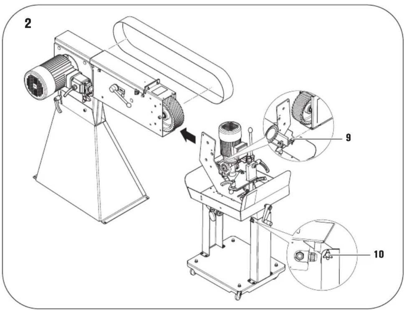
text_image
2 9 10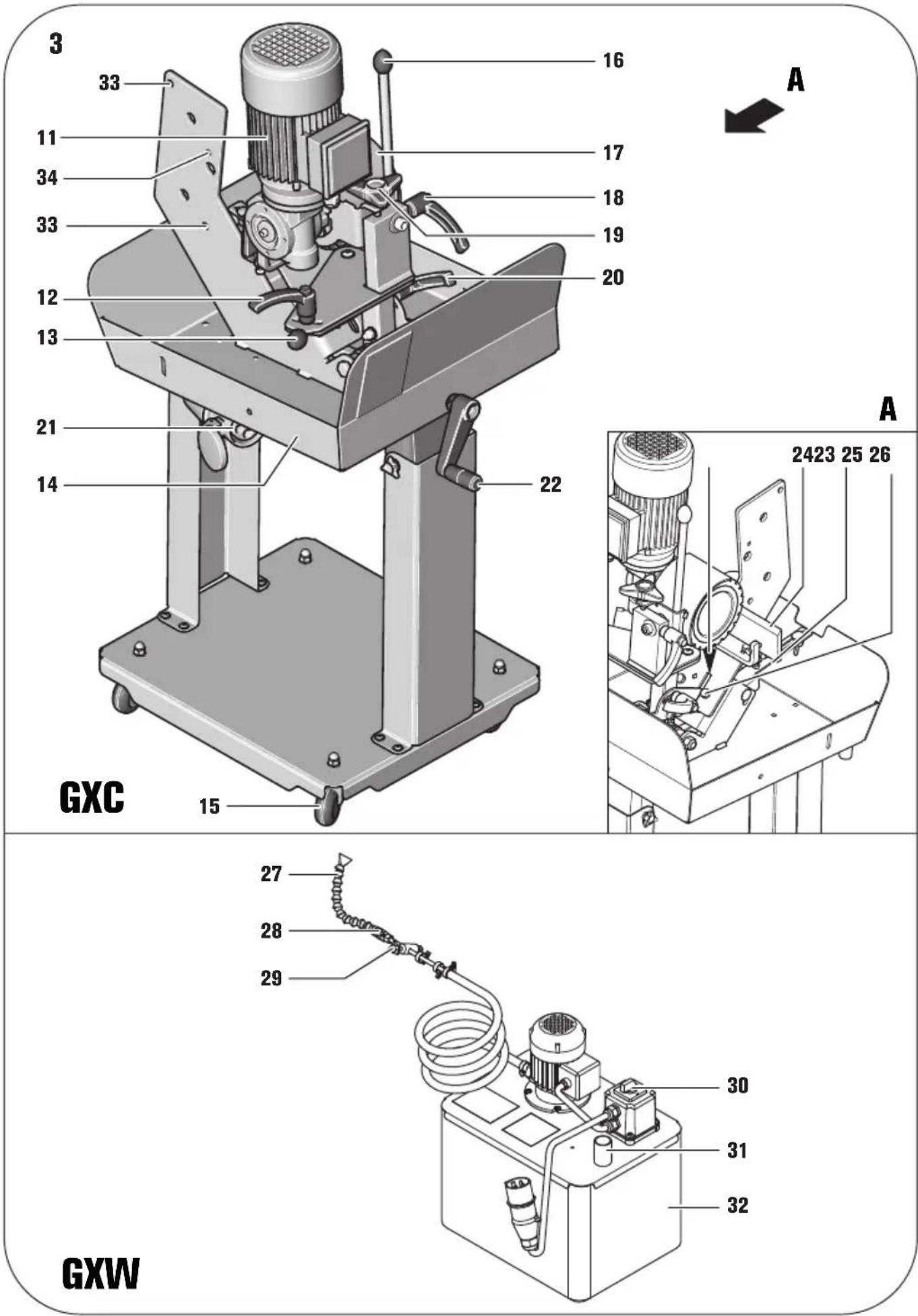
4

natural_image
Technical line drawing of a mechanical device with gears and control panels (no text or symbols)5

text_image
φ10D = 12-100 mm D = 10-12 mm 1.2.
text_image
ca 1/3R R ca 1/2R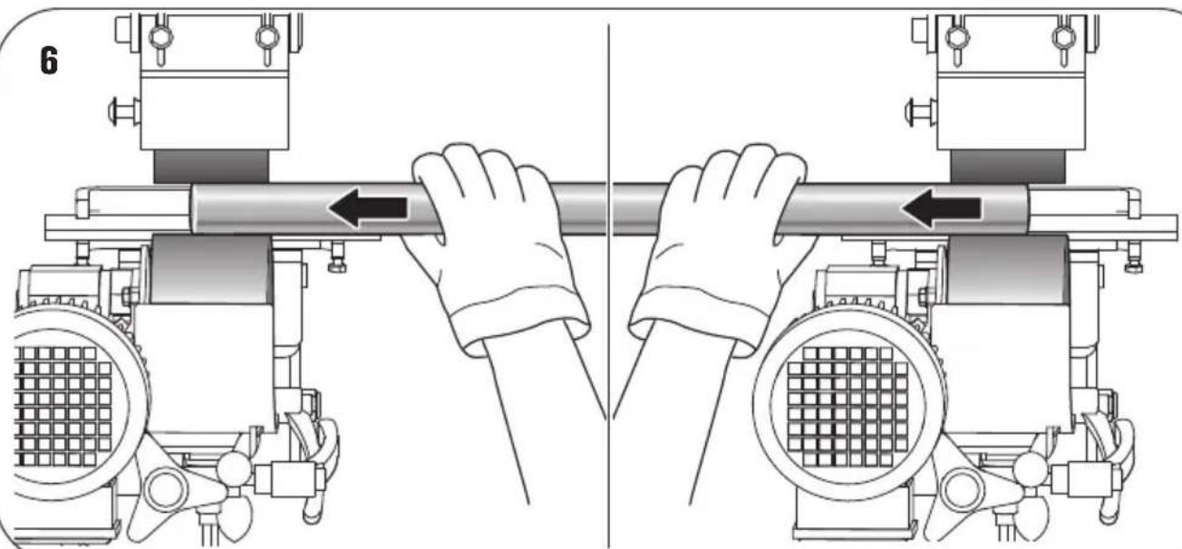
natural_image
Illustration of two hands operating a cylindrical mechanical component with directional arrows indicating movement (no text or symbols present)Translation of the Original Instructions.
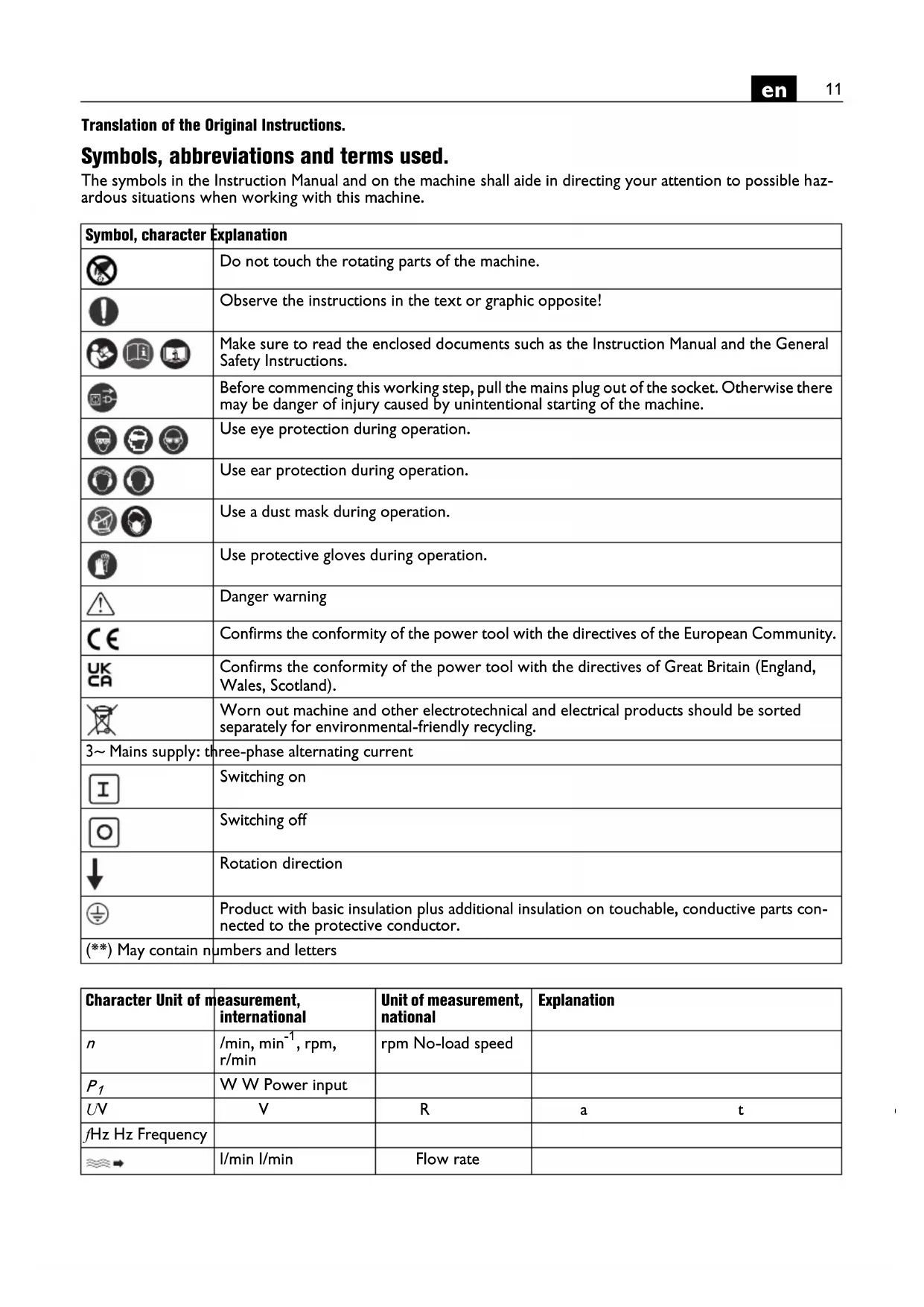
Symbols, abbreviations and terms used.
The symbols in the Instruction Manual and on the machine shall aide in directing your attention to possible hazardous situations when working with this machine.
| Symbol, character | Explanation |
 | Do not touch the rotating parts of the machine. |
 | Observe the instructions in the text or graphic opposite! |
   | Make sure to read the enclosed documents such as the Instruction Manual and the General Safety Instructions. |
 | Before commencing this working step, pull the mains plug out of the socket. Otherwise there may be danger of injury caused by unintentional starting of the machine. |
   | Use eye protection during operation. |
 | Use ear protection during operation. |
  | Use a dust mask during operation. |
 | Use protective gloves during operation. |
 | Danger warning |
 | Confirms the conformity of the power tool with the directives of the European Community. |
 | Confirms the conformity of the power tool with the directives of Great Britain (England, Wales, Scotland). |
 | Worn out machine and other electrotechnical and electrical products should be sorted separately for environmental-friendly recycling. |
| 3~ Mains supply: three-phase alternating current | |
 | Switching on |
 | Switching off |
| [8794] | Rotation direction |
 | Product with basic insulation plus additional insulation on touchable, conductive parts connected to the protective conductor. |
| (**) May contain numbers and letters | |
| Character Unit of measurement, international | Unit of measurement, national | Explanation |
| n/min, min ^-1 , rpm, r/min | rpm No-load speed | |
| P1W W Power input | ||
| UVV | R | a t |
| fHz Hz Frequency | ||
| ↔l/min l/min | Flow rate | |
| kg kg Weight according to EPTA-Procedure 01 | ||
| m, s, kg, A, mm, V, W, Hz, N, °C, dB, min, m/s^2 | Basic and derived units of measurement from the international system of units SI. |
For your safety.

Do not use this machine before you have thoroughly read and completely understood these operating instructions, including the figures, specifications, and safety regulations.
Please also observe the relevant national industrial safety regulations (e.g. in Germany: BGV A2, BGR 500).
Non-observance of the safety instructions in the said documentation can lead to an electric shock, burns and/or severe injuries.
This Instruction Manual should be kept for later use and enclosed with the power tool, should it be passed on or sold.

Read and observe the operating instructions of the belt grinder GX75, which is to be mounted to this machine.
For assembly of the cylindrical grinding device to the belt grinder, use only the fastening material provided.
Faulty assembly can cause the cylindrical grinding device to loosen from the belt grinder during operation and lead to serious accidents.
Intended use of the machine.
The cylindrical grinding device GXC is to be used together with the belt grinder GX75 exclusively for grinding and polishing round steel pipes, light metal pipes as well as solid round stock with diameters D = 10–100 mm using the application tools and accessories recommended by FEIN in weather-protected environments.
The cooling unit GXW is intended for cooling of the workpiece.
Special safety instructions.
Wear personal protective equipment. Depending on application, use face shield, safety goggles or safety glasses. Where appropriate, wear dust mask, hearing protectors, gloves and workshop apron capable of stopping small abrasive or workpiece fragments. The eye protection must be capable of stopping flying debris generated by various operations. The dust mask or respirator must be capable of filtrating particles generated by your operation. Prolonged exposure to high intensity noise may cause hearing loss.
While working, do not wear loose clothing, jewellery or open, long hair. Despite protective devices, loose objects can be snagged or caught by moving parts and lead to injury.
Before switching on, make sure that no workpiece is inserted in the cylindrical grinding device. The workpiece can be thrown from the machine and cause serious accidents.

Never touch the running grinding belt. Danger of injury.
In situations of danger, immediately press the safety pushbutton. The machine runs on for approx. 50 seconds.
Clean the ventilation openings on the power tool at regular intervals using non-metal tools. The blower of the motor draws dust into the housing. An excessive accumulation of metallic dust can cause an electrical hazard.
The mains plug of the machine may be mounted only by a qualified electrician. The protective conductor in the mains socket outlet must be connected with the protective earthing of the mains supply.
Pull out the mains plug for maintenance and repair! Switching the machine on unintentionally can lead to serious injuries.
Have the electrical safety of the machine checked regularly in accordance with statutory regulations. For machines that have not been checked, there may be danger of electrical shock!
Check the rotation direction of the motor before starting the operation of the machine for the first time. If the rotation direction of the motor is incorrect, the workpiece can be thrown from the machine and cause an accident. The rotation direction may be changed only by a qualifiedelectrician.
Always work with great care and attention, especially when inserting and removing the material. If your attention fades, your hands may be seriously injured.
The surface being worked can become very hot. Do not touch it with your hands.
Be careful when working short or thin material. When inserting and removing, your hands may be caught by the grinding belt or brake wheel, causing serious injury.
For longer pipes and round stock, we recommend the using the pipe guide GXIS-1/GXIS-2.
Exercise caution after switching off. The machine runs on for approx. 50 seconds. Carry out adjustments and maintenance only when the grinding belt is stopped.
Handling hazardous dusts
For work procedures with this power tool where material is removed, dusts develop that can be hazardous to one's health.
Contact with or inhaling some dust types, e. g. asbestos and asbestos-containing materials, lead-containing coatings, metal, some wood types, minerals, silicate particles from materials containing stone, paint solvents, wood preservatives, antifouling paints for vessels, can trigger allergic reactions to the operator or bystanders and/or lead to respiratory infections, cancer, birth defects or other reproductive harm. The risk from inhaling dusts depends on the exposition. Use dust extraction matched appropriately for the developing dust, as well as personal protective equipment and provide for good ventilation of the workplace. Leave the processing of asbestos-containing materials to specialists.
Wood and light-metal dust, hot mixtures of grinding dust and chemical materials can self-ignite under unfavourable conditions or cause an explosion. Avoid sparking in the direction of the dust collector as well as overheating of the power tool and the materials being sanded, empty the dust collector/container in time, observe the material manufacturer's working instructions, as well as the relevant regulations in your country for the materials being worked.
At a glance.
1 Grinding belt tensioning device (GX75)
2 Cover/stop (GX75)
3 Spark guard (GX75)
4 Star-knob bolt, chip/grinding-dust box (GX75)
5 Grinding rest (GX75)
6 Dust collector (GX75)
7 Lever for tilting device (GX75)
8 Side cover (GX75)
9 Wing bolt
10 Star-knob bolt for adjustment of GXC
11 Brake-wheel drive motor
12 Star-knob bolts for brake-wheel parallelism
13 Handle
14 Basin
15 Casters
16 Lever for applying brake wheel against the workpiece
17 Brake wheel
18 Clamping lever
19 Star-knob bolt for brake-wheel inclination
20 Star-knob bolt for brake-wheel clearance
21 Connection socket
22 Crank for adjusting the feed pressure
23 Gap opening
24 Guide rail
25 Screw/wing nut
26 Screw for guide-rail adjustment
27 Coolant hose with nozzle
28 Shut-off valve
29 Magnetic holder
30 On/off switch for coolant pump
31 Drain hose for coolant return
32 Coolant tank
33 Drill hole
34 Threaded hole
Assembly instructions (figures 1-3).
Belt grinder GX75.

Before any work on the machine itself, pull the mains plug.
Dismount the spark guard (3).
Dismount the grinding rest (5), the chip/grinding-dust box (6) and the star-knob bolt (4).
Open side cover (8).
Loosen the tensioning device (1) and remove the grinding belt.
Shut the side cover.
Loosen the lever of tilting device (7) and set the belt grinder to a horizontal position.
Cylindrical grinding device GXC(figure 2).
Remove the unit from its packaging and fit the accessories as described in the data sheet.
Position the cylindrical grinding device against the belt grinder and align the drill holes (33).
Connect both machines with the two levers as well as the screws with wing nuts (9).
Lightly tilt the device toward the front.
Tighten the levers of the tilting device (7).
Loosen the four star-knob bolts (10) below basin (14) and align the bottom part of the cylindrical grinding device at the floor.
Tighten the four star-knob bolts (10) below basin (14) again.

The power cable must be connected by a qualified electrician to the connection point in the switch of the belt grinder GX75 according to the wiring diagram (see Appendix).
Coolant unit GXW (figures 3+4).
Position the tank on the base plate of the cylindrical grinding device.
Fill approx. 10–15 liters of coolant into the coolant tank.
Place the lid with the pump unit onto the tank and mount the drain hose (31) to the connection sleeve of the tank (14).
Mount coolant hose (27) on the cylindrical grinding device with magnetic holder (29) in the threaded hole (34).

The coolant hose must be mounted in such a manner that the brake wheel or workpiece cannot catch hold of it.
Plug the plug of the coolant unit into socket outlet (21).
Mounting/replacing the grinding belt

Before any work on the machine itself, pull the mains plug.
Loosen the tensioning device (1) and mount a 75 x 2000 mm long grinding belt.

The running-direction marking of the grinding belt must correspond with the rotation direction.
Tension the grinding belt with the tensioning device (1).
Move the grinding belt manually and observe, if it moves off towards the left or right of the contact roller. Adjust the guidance of the drive wheel on the belt grinder such that the grinding belt runs centrally. The exact calibration is carried out while the machine is running.
Switch the belt grinder on. Check if the contact pulley rotates in the direction of the arrow.
Switch the belt grinder off again.

If the contact disc rotates in the opposite direction of the arrow, the motor's direction of rotation must be changed by a qualified electrician.
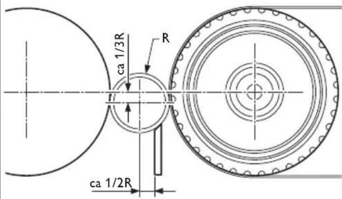
Adjusting the guide rail (figures 3A+5).

Before any work on the machine itself, pull the mains plug.
Loosen both screws (26) and adjust the clearance of the guide rail to the brake wheel:
- Pipe diameter 10–12 mm: Adjustment according to figure "1".
- Pipe diameter 12–100 mm: Adjustment according to figure "2".
Tighten screws (26) again.
Adjusting the brake wheel (figure 3).

Before any work on the machine itself, pull the mains plug.
Adjusting the parallelism.
Loosen star-knob bolt (12) and adjust the brake wheel (17) with handle (13) in such a manner that it runs parallel to the contact disc when viewed from above. This helps to achieve a uniform feed pressure and a uniform grinding pattern. The optimal setting must be determined by practical testing.
Adjusting the incline.
Release the clamping lever (18) and adjust the brake wheel (17) with the star-knob bolt (19) in such a manner that is lightly inclined to the left with reference to the workpiece.

The more the brake wheel is inclined, the higher the feed speed. The optimal setting must be determined by practical testing.
Setting the clearance between brake wheel, workpiece and contact roller.
Loosen star-knob bolt (9).
Tilt the drive unit back with lever (16).
Place in the workpiece to be ground.
Tilt the drive unit toward the front again so that the brake wheel faces against the workpiece.
Adjust the gap clearance (23) to 1 mm.
Tighten star-knob bolt (20) again.
Adjusting the feed pressure.
Adjust the feed pressure of the brake wheel against the workpiece with crank (22):
- Turning in clockwise direction: High feed pressure.
- Turning in anticlockwise direction: Low feed pressure.
Excessive feed pressure can lead to increased wear of the brake wheel and the grinding belt!
Operating instructions.
Switching on and off.

Do not switch the machine on until all required settings have been made. Make sure that no workpiece is inserted in the machine.
Plug the plug of the cylindrical grinding device into the socket outlet on the belt grinder.
Switching the belt grinder/cylindrical grinding device on/off.
GX75\*
Switching on:
Disengage and fold up the safety pushbutton (15 ^* ).
Press pushbutton "I" (17*).

The cylindrical grinding device is switched on automatically.

Check the rotation direction of the brake wheel. The rotation direction of the motor may only be reversed by a qualified electrician.
Switching off:
Fold up safety pushbutton (15 ^ ). Press pushbutton "0" (17 ^ ).
The cylindrical grinding device is switched off automatically.

After switching off, the machine runs on for approx. 50 seconds.
(* see operating instructions of the machine)
Safety pushbutton.
In situations of danger, press the safety pushbutton to switch the machine off.
Switching the coolant pump on/off.
Set the switch to position "1". The coolant pump must always be switched on for high removal rates.

Wear safety glasses/goggles.

Before starting work, make sure that all settings described above have been correctly made and checked.
Grinding pipes (figures 5+6).
Tilt the brake wheel back with lever (16).
Insert the workpiece at least 30 mm deep into the pipe guide.
Open the coolant valve (28). Regulate the coolant rate with shut-off valve (28).
Tilt the brake wheel forward again with lever (16) so that the workpiece rotates and runs through the machine.
Pull lever (16) back again when the workpiece is still approx. 30 mm in the pipe guide.
Take the workpiece out of the machine.

If the feed speed is too high or too low, the inclination of the brake wheel must be changed.
Noise emission values.
Idle Sanding
A-weighted emission pressure power level measured at the workplace L_pA (re 20 Pa), in decibels 83.5 94
Measuring uncertainty K_pA , in decibels 4 4 Measured A-weighted sound power level L_wA (re 1 pW), in decibels 93.5 100.5
Measuring uncertainty K_wA , in decibels 2.5 2.5
Operating conditions
| Speed (rpm) | 3000 | 3000 |
| Material | - | Stainless steel |
| Dimension | Pipe, diameter | |
| - | 42.4 mm | |
| Grinding belt | GRIT by Fein | |
| - | 120R | |
REMARK: The sum of the measured emission value and respective measuring inaccuracy represents the upper limit of the values that can occur during measuring.


Wear hearing protection!
Measured values determined in accordance with the corresponding product standard (see last page in this Instruction Manual).
Repair and customer service.

Before any work on the machine itself, pull the mains plug.

Repairs may be carried out only by qualified persons in conformity with the valid regulations.
For repairs, we recommend our FEIN customer service centre, the FEIN authorised service centres and FEIN agencies.
When the machine's power supply cable is damaged, it must be replaced using a specially prepared power supply cable, available from your FEIN customer service agent.
The current spare parts list of this machine can be found on the Internet under www.fein.com.
Daily maintenance
Empty the coolant tank. Separate and dispose of coolant and metal dust.
Clean the basin (14). If required, remove any clogs in the drain system.
Cleaning the exterior of the machine with compressed air.
Warranty and liability.
The warranty for the product is valid in accordance with the legal regulations in the country where it is marketed. In addition, FEIN also provides a guarantee in accordance with the FEIN manufacturer's warranty declaration.
The delivery scope of your machine may include only a part of the accessories described or shown in this instruction manual.
Declaration of conformity.
This CE declaration is only valid for European Union and EFTA (European Free Trade Association) countries and only for products intended for the EU- or EFTA market. After placing the product on the EU market the UKCA mark loses its mark validity.
The UKCA declaration is only valid for the Great Britain market (England, Wales and Scotland) and only for products intended for the Great Britain market. After placing the product on the Great Britain market the CE mark loses its mark validity.
FEIN declares itself solely responsible for this product conforming with the relevant provisions given on the last page of this Instruction Manual.
Technical documents at: C. & E. Fein GmbH, D-73529 Schwäbisch Gmünd
Environmental protection, disposal.
Packaging, worn out machines and accessories should be sorted for environment-friendly recycling.
Connection diagrams.
Type GXC Page 102
Type GXC2V Page 103
Type GXW Page 104
Type GXW2V Page 105
rato L_WA (re 1 pW), in
decibel 93,5 100,5
Schuurband GRIT by Fein
- 120R
Correia abrasiva GRIT by Fein
- 120R
Slipebånd GRIT by Fein - 120R
China RoHS Status Certificate
中国 RoHS 认证概况
Table of Toxic and Hazardous Substances/Elements and their Content
as required by China's Management Methods for Controlling Pollution by Electronic Information Products
有毒有害物质 / 成分及其含量表
This CE declaration is only valid for European Union and EFTA (European Free Trade Association) countries and only for products intended for the EU or EFTA market. After placing the product on the EU market the UKCA mark loses its mark validity.

EN ISO 3744:2010
EN ISO 11202:2010
EN ISO 4871:2009
EN ISO 12100:2011
2011/65/EU, 2006/42/EG
U. Hergosell
i. V. S. Böhm i. V. Dr. M. Hergesell
Director of Quality Director of Product Management Development
The UKCA declaration is only valid for the Great Britain market (England, Wales and Scotland) and only for products intended for the Great Britain market. After placing the product on the Great Britain market the CE mark loses its mark validity.

EN ISO 3744:2010
EN ISO 11202:2010
EN ISO 4871:2009
EN ISO 12100:2011
Supply of Machinery Regulations 2008,
The Restriction of the Use of Certain Hazardous Substances in Electrical and Electronic Equipment
Regulations 2012
U. Hergosell
i. V. S. Böhm i. V. Dr. M. Hergesell
Director of Quality
Management Development
Director of Product