WPO 10-25 E Set - Sander Fein - Free user manual and instructions
Find the device manual for free WPO 10-25 E Set Fein in PDF.

| Brand | Fein |
| Model | WPO 10-25 E Set |
| Product Type | Power Polisher / Sander |
| Category | Random Orbital Sander |
| Rated Voltage | 230 V |
| Frequency | 50/60 Hz |
| Power Consumption | 1100 W |
| No-Load Speed | 1000 – 2500 rpm |
| Pad Type | Self-adhesive and hook-and-loop |
| Weight (according to EPTA) | 2.8 kg |
| Insulation | Double insulation |
| Sound Pressure Level LpA | 85 dB(A) |
| Sound Power Level LwA | 96 dB(A) |
| Vibration Value (polishing) a_h,P | 2.5 m/s² |
| Vibration Value (sanding) a_h,DS | 3.5 m/s² |
| Max. Accessory Diameter | 125 mm |
| Clamping Flange Thread | M14 |
| Cable Length | 4 m |
| Warranty | Compliant with legal regulations |
| Included Accessories | Lambswool pad, self-adhesive pad, abrasive sheets, brushes, polishing discs |
Frequently Asked Questions - WPO 10-25 E Set Fein
User questions about WPO 10-25 E Set Fein
0 question about this device. Answer the ones you know or ask your own.
Ask a new question about this device
Download the instructions for your Sander in PDF format for free! Find your manual WPO 10-25 E Set - Fein and take your electronic device back in hand. On this page are published all the documents necessary for the use of your device. WPO 10-25 E Set by Fein.
USER MANUAL WPO 10-25 E Set Fein
OBJ DOKU-000001711-002.6m Page 1 Tuesday, January 21, 2014 10:36 AM

▶WP010-25E 7 221 63
▶WP014-15E 7 221 48
▶WP014-25E 7 221 49

CE
EN 60745, EN 55014, EN 61000-3-2, EN 61000-3-3 2011/65/EU, 2006/42/EG, 2004/108/EG
07.19
Chunib
Hammersdorf
Dr. Schreiber
Quality Manager
Manager of R&D department
FEIN Service
C. & E. FEIN GmbH
Hans-Fein-Straße 81
a C. E. FEN (dual-periods of currency, additional currencies, financial assets, and other) is at 11.00 by 27.00 to 10.
natural_image
3D rendering of a mechanical power tool with a circular base and handle (no text or symbols visible)2
WP010-25E WP014-15E WP014-25E
7 221 63 7 221 48 7 221 49
| P_1 | W 800 1200 1200 |
| P_2 | W 550 750 750 |
| n | /min, min ^-1 ,rpm, r/min 900 – 2500 500 – 1500 900–2500 |

_D mm 150 230 230

MM14 M14 M14
| 1 | m | m | 2 | 0 |
2 0 2

kg 2,2 2,5 2,5

dB 84 84 84

dB 3 3 3

dB 95 95 95

dB 3 3 3

dB 100 100 100

dB 3 3 3


OBJ BUCH-0000000053-002.book Page 4 Tuesday, January 21, 2014 10:37 AM


4


6

flowchart
graph TD
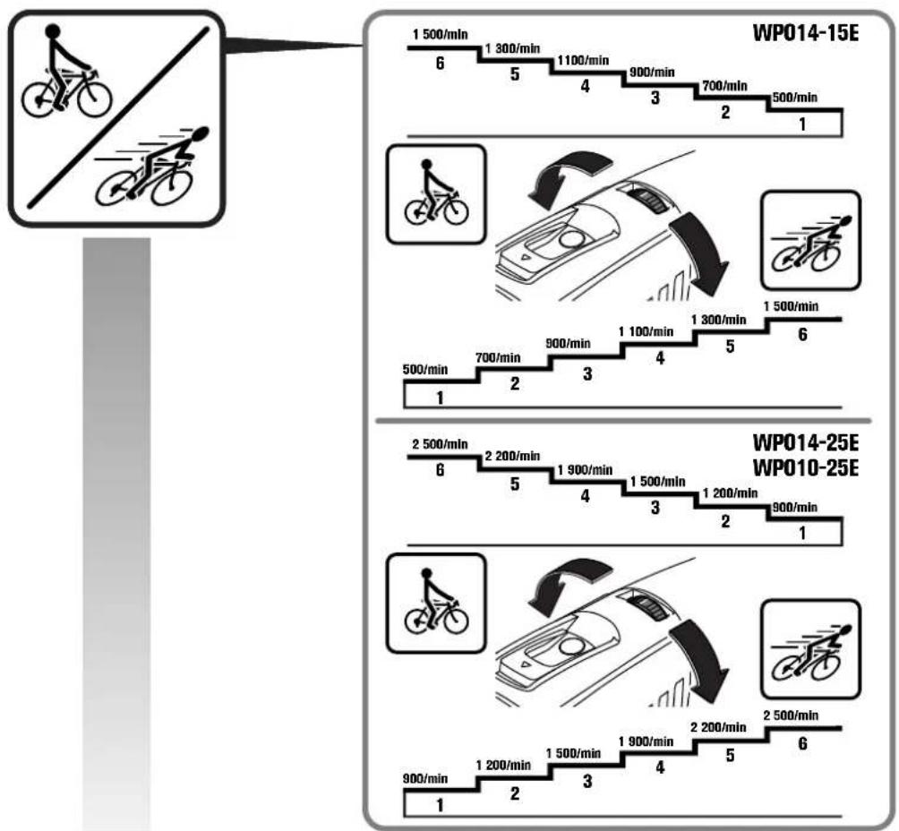
A["WP014-15E"] --> B["1 500/min 6"]
B --> C["1 300/min 5"]
C --> D["1 100/min 4"]
D --> E["900/min 3"]
E --> F["700/min 2"]
F --> G["500/min 1"]
H["WP014-25E"] --> I["2 500/min 6"]
I --> J["2 200/min 5"]
J --> K["1 900/min 4"]
K --> L["1 500/min 3"]
L --> M["1 200/min 2"]
M --> N["900/min 1"]
O["WP010-25E"] --> P["900/min 1"]
P --> Q["1 200/min 2"]
Q --> R["1 500/min 3"]
R --> S["1 900/min 4"]
S --> T["2 200/min 5"]
T --> U["2 500/min 6"]


OBJ BUCH-0000000053-002.book Page 7 Tuesday, January 21, 2014 10:37 AM


7


OBJ BUCH-0000000053-002.book Page 10 Tuesday, January 21, 2014 10:37 AM

10


de
Original Instructions.
Symbols, abbreviations and terms used.
| Symbol, character Explanation | |
| General prohibition sign. This action is prohibited. | |
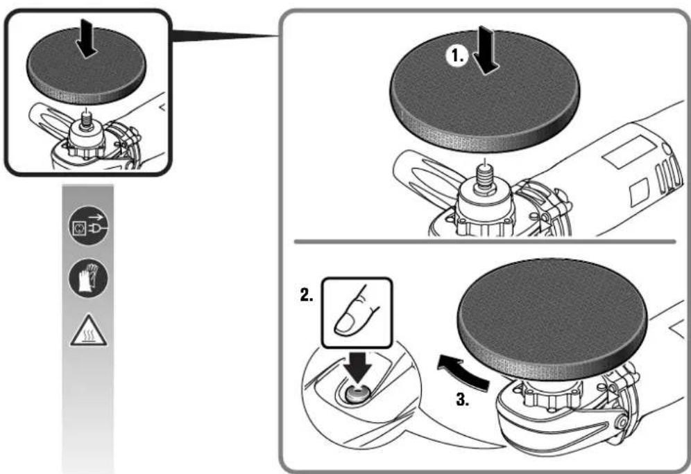
| Do not touch the rotating parts of the power tool. | |
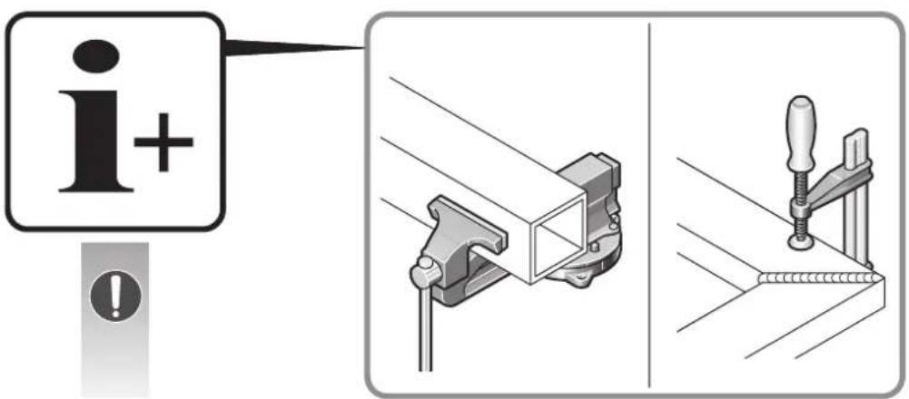
| Observe the instructions in the text or graphic opposite! | |
| Make sure to read the enclosed documents such as the Instruction Manual and the General Safety Instructions. | |
| Before commencing this work step, pull the mains plug out of the socket. Otherwise there will be danger of injury if the power tool should start unintentionally. | |
| Use eye protection during operation. | |
| Use ear protection during operation. | |
| Use protective gloves during operation. | |
| A surface that can be touched may be very hot and thus hazardous. | |
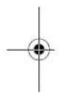
| Gripping surface | |
| Additional information. | |
| CE | Confirms the conformity of the power tool with the directives of the European Community. |
| WARNING | This sign indicates a possible dangerous situation that could cause severe or fatal injury. |
| Worn out power tools and other electrotechnical and electrical products should be sorted separately for environmental-friendly recycling. | |
| Product with double or reinforced insulation | |
| Low speed | |
| High speed | |
| Character Unit of measurement, international | Unit of measurement, national | Explanation |
| n/min, min ^-1 , rpm, r/min | rpm Rated speed | |
| P1W | W | P o |
| P2W W Output | ||
| UVV | R | a t |
| fHz Hz Frequency | ||
| M...mm mm Size of metric thread | ||
| ∅ mm mm Diameter of a round part | ||
| mm mm ∅ | ||
| mm mm M=Thread for clamping flange | D=Max. application tool diameter | |
| l=Length of mounting thread | ||
| kg | kg | |

w
e

en
| Character Unit of measurement, international | Unit of measurement, national | Explanation |
| L_pA | dB dB Sound pressure level | |
| L_wA | dB dB Sound power level | |
| L_pCpeak | dB dB Peak sound pressure level | |
| K... | Uncertainty | |
| a | m/s ^2 | m/s ^2 |
| a_h,P | m/s ^2 | m/s ^2 |
| a_h,DS | m/s ^2 | m/s ^2 |
| m, s, kg, A, mm, V, W, Hz, N, °C, dB, min, m/s ^2 | m, s, kg, A, mm, V, W, Hz, N, °C, dB, min, m/s ^2 |
For your safety.
WARNING
Read all safety warnings and all instructions. Failure to follow the
warnings and instructions may result in electric shock, fire and/or serious injury.
Save all warnings and instructions for future reference.
Do not use this power tool before you have thoroughly read and completely understood this Instruction Manual and the enclosed "General Safety Instructions" (document number
3 41 30 054 06 1). The documents mentioned should be kept for later use and enclosed with the power tool, should it be passed on or sold.
Please also observe the relevant national industrial safety regulations.
Intended use of the power tool:
Hand-guided polisher for dry polishing, sanding with sanding sheets and brushing on surfaces of metal, stone, plastic, wood, composite materials, paint/varnish, filler and similar materials in weather-protected environments with the application tools and accessories recommended by FEIN.
This power tool is also suitable for use with AC generators with sufficient power output that correspond to the Standard ISO 8528, design type G2. This Standard is particularly not complied with when the so-called distortion factor exceeds 10% . When in doubt, please refer to the generator instruction/specification guide.
Safety warnings common for sanding with sanding discs, working with wire brushes and polishing
This power tool is intended to function as a sander, wire brush and polisher. Read all safety warnings, instructions, illustrations and specifications provided with this power tool. Failure the follow all instructions listed below may result in electric shock, fire and/or serious injury.
Operations such as grinding or cutting-off are not recommended to be performed with this power tool. Operations for which the power tool was not designed may create a hazard and cause personal injury.
Do not use accessories which are not specifically designed and recommended by the tool manufacturer. Just because the accessory can be attached to your power tool, it does not assure safe operation.
The rated speed of the accessory must be at least equal to the maximum speed marked on the power tool. Accessories running faster than their rated speed can break and fly apart.
The outside diameter and the thickness of your accessory must be within the capacity rating of your power tool. Incorrectly sized accessories cannot be adequately guarded or controlled.
Application tools with threaded inserts must match the grinder spindle thread. For accessories mounted by flanges, the arbour hole of the accessory must fit the locating diameter of the flange. Accessories that do not match the mounting hardware of the power tool will run out of balance, vibrate excessively and may cause loss of control.
Do not use a damaged accessory. Before each use inspect the accessory such as abrasive wheels for chips and cracks, backing pad for cracks, tear or excess wear, wire brush for loose or cracked wires. If power tool or accessory is dropped, inspect for damage or install an undamaged accessory. After inspecting and installing an accessory, position yourself and bystanders away from the plane of the rotating accessory and run the power tool at maximum no-load speed for one minute. Damaged accessories will normally break apart during this testtime.
Wear personal protective equipment. Depending on application, use face shield, safety goggles or safety glasses. Where appropriate, wear dust mask, hearing protectors, gloves and workshop apron capable of stopping small abrasive or workpiece fragments. The eye protection must be capable of stopping flying debris generated by various operations. The dust mask or respirator must be capable of filtrating particles generated by your operation. Prolonged exposure to high intensity noise may cause hearing loss.
Keep bystanders a safe distance away from work area. Anyone entering the work area must wear personal protective equipment. Fragments of workpiece or of a broken accessory may fly away and cause injury beyond immediate area of operation.
Hold the power tool by insulated gripping surfaces only, when performing an operation where the cutting accessory may contact hidden wiring or its own cord. Cutting accessory contacting a "live" wire may make exposed metal parts of the power tool "live" and could give the operator an electric shock.
Position the cord clear of the spinning accessory. If you lose control of the power tool, the cord may be cut or snagged and your hand or arm may be pulled into the spinning accessory.
Never lay the power tool down until the accessory has come to a complete stop. The spinning accessory may grab the surface and pull the power tool out of your control.
Do not run the power tool while carrying it at your side. Accidental contact with the spinning accessory could snag your clothing, pulling the accessory into your body.
Regularly clean the power tool's air vents. The motor's fan will draw the dust inside the housing and excessive accumulation of powdered metal may cause electrical hazards.
Do not operate the power tool near flammable materials. Sparks could ignite these materials.
Do not use accessories that require liquid coolants. Using water or other liquid coolants may result in electrocution or shock.
Kickback and related warnings
Kickback is a sudden reaction to a pinched or snagged rotating wheel, backing pad, brush or any other accessory. Pinching or snagging causes rapid stalling of the rotating accessory which in turn causes the uncontrolled-power tool to be forced in the direction opposite of the accessory's rotation at the point of the binding.
For example, if an abrasive wheel is snagged or pinched by the workpiece, the edge of the wheel that is entering into the pinch point can dig into the surface of the material causing the wheel to climb out or kick out. The wheel may either jump toward or away from the operator, depending on direction of the wheel's movement at the point of pinching. Abrasive wheels may also break under these conditions.
Kickback is the result of power tool misuse and/or incorrect operating procedures or conditions and can be avoided by taking proper precautions as given below.
Maintain a firm grip on the power tool and position your body and arm to allow you to resist kickback forces.
Always use auxiliary handle, if provided, for maximum control over kickback or torque reaction during start-up. The operator can control torque reactions or kickback forces, if proper precautions are taken.
Never place your hand near the rotating accessory. Accessory may kickback over your hand.
Do not position your body in the area where power tool will move if kickback occurs. Kickback will propel the tool in direction opposite to the wheel's movement at the point of snagging.
Use special care when working corners, sharp edges, etc. Avoid bouncing and snagging the accessory. Corners, sharp edges or bouncing have a tendency to snag the rotating accessory and cause loss of control or kickback. Do not attach a saw chain woodcarving blade or toothed saw blade. Such blades create frequent kickback and loss of control over the power tool.
Safety warnings specific for sanding operations
Do not use excessively oversized sanding disc paper. Follow manufacturers recommendations, when selecting sanding paper. Larger sanding paper extending beyond the sanding pad presents a laceration hazard and may cause snagging, tearing of the disc, or kickback.
Safety warnings specific for polishing operations
Do not allow any loose portion of the polishing bonnet or its attachment strings to spin freely. Tuck away or trim any loose attachment strings. Loose and spinning attachment strings can entangle your fingers or snag on the workpiece.
Safety warnings specific for wire brushing operations
Be aware that wire bristles are thrown by the brush even during ordinary operation. Do not overstress the wires by applying excessive load to the brush. The wire bristles can easily penetrate light clothing and/or skin.
If the use of a guard is recommended for wire brushing, do not allow any interference of the wire wheel or brush with the guard. Wire wheel or brush may expand in diameter due to work load and centrifugal forces.
Further safety warnings
Use elastic spacers/liners when these are provided with the grinding accessory.
Make sure that the application tools are mounted in accordance with the manufacturers instructions. The mounted application tools must be able to rotate freely. Incorrectly mounted application tools can become loose during operation and be thrown from the machine.
Handle grinding accessories carefully and store them according to the manufacturer's instructions. Damaged grinding accessories can develop cracks and burst during operation.
When using application tools with a threaded insert, take care that the thread in the application tool is long enough to hold the spindle length of the power tool. The thread in the application tool must match the thread on the spindle. Incorrectly mounted application tools can loosen during operation and cause injuries.
Do not direct the power tool against yourself, other persons or animals. Danger of injury from sharp or hot application tools.
Use a stationary extraction system, blow out ventilation slots frequently and connect a residual current device (RCD) on the line side. When working metal under extreme operating conditions, it is possible for conductive dust to settle in the interior of the power tool. The total insulation of the power tool can be impaired.
Do not rivet or screw any name-plates or signs onto the power tool. If the insulation is damaged, protection against an electric shock will be ineffective. Adhesive labels are recommended.
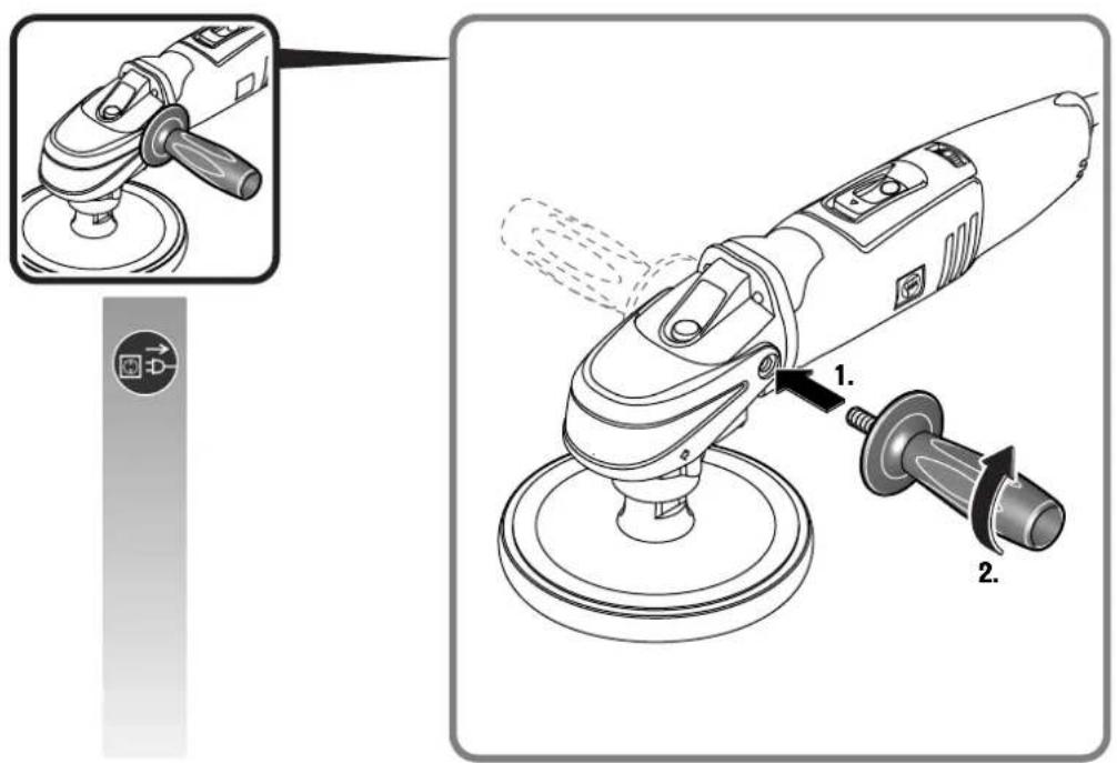
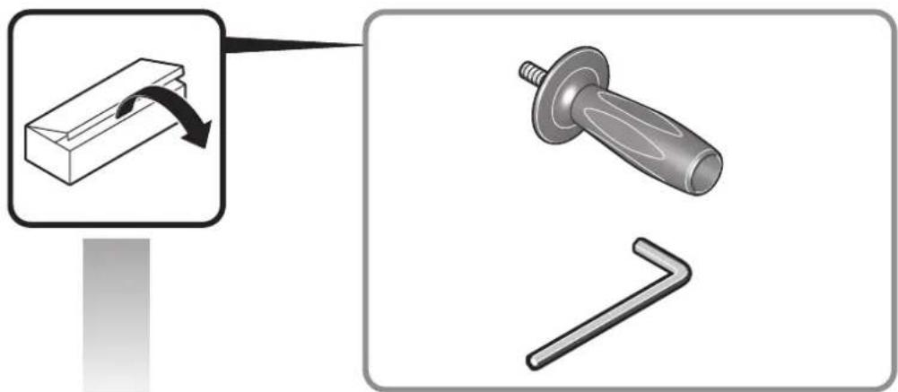
Always work with the auxiliary handle. The auxiliary handle ensures reliable guiding of the power tool.


en
Before putting into operation, check the mains connection and the mains plug for damage.
Recommendation: The tool should always be supplied with power via a residual current device (RCD) with a rated current of 30 mA or less.
Hand/arm vibrations
The vibration emission level given in this information sheet has been measured in accordance with a standardised test given in EN 60745 and may be used to compare one tool with another. It may be used for a preliminary assessment of exposure.
The declared vibration emission level represents the main applications of the tool. However, if the tool is used for different applications, with different accessories or poorly maintained, the vibration emission may differ. This may significantly increase the exposure level over the total working period.
An estimation of the level of exposure to vibration should also take into account the times when the tool is switched off or when it is running but not actually doing the job. This may significantly reduce the exposure level over the total working period.
Identify additional safety measures to protect the operator from the effects of vibration such as: maintain the tool and the accessories, keep the hands warm, organisation of work patterns.
Handling hazardous dusts
For work procedures with this power tool where material is removed, dusts develop that can be hazardous to one's health.
Contact with or inhaling some dust types, e. g. asbestos and asbestos-containing materials, lead-containing coatings, metal, some wood types, minerals, silicate particles from materials containing stone, paint solvents, wood preservatives, antifouling paints for vessels, can trigger allergic reactions to the operator or bystanders and/or lead to respiratory infections, cancer, birth defects or other reproductive harm. The risk from inhaling dusts depends on the exposition. Use dust extraction matched appropriately for the developing dust, as well as personal protective equipment and provide for good ventilation of the workplace. Leave the processing of asbestos-containing materials to specialists.
Wood and light-metal dust, hot mixtures of sanding dust and chemical materials can self-ignite under unfavourable conditions or cause an explosion. Avoid sparking in the direction of the dust collector as well as overheating of the power tool and the materials being sanded, empty the dust collector/container in time, observe the material manufacturer's working instructions, as well as the relevant regulations in your country for the materials being worked.
Operating Instructions.
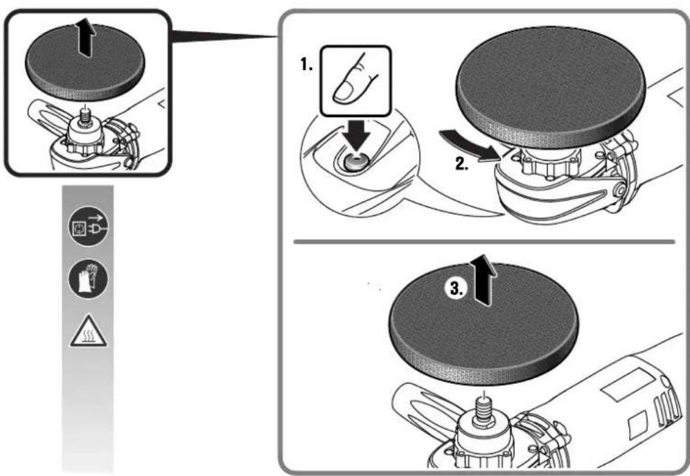
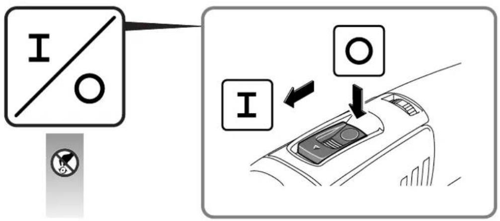
Press the locking button only when the motor is stopped (see page 5).
Repair and customer service.

When working metal under extreme operating conditions, it is possible for conductive dust to settle in the interior of the power tool.
The total insulation of the power tool can be impaired. Blow out the interior of the power tool via the ventilation slots frequently with dry and oil-free compressed air, and connect a residual current device (RCD) on the line side.
If the supply cord of this power tool is damaged, it must be replaced by a specially prepared cord available through the FEIN customer service centre.
The current spare parts list for this power tool can be found in the Internet at www.fein.com.
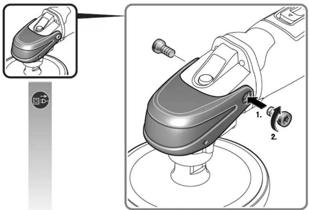
If required, you can change the following parts yourself: Application tools, auxiliary handle, safety guard, work arbors, flanges.
Warranty and liability.
The warranty for the product is valid in accordance with the legal regulations in the country where it is marketed. In addition, FEIN also provides a guarantee in accordance with the FEIN manufacturer's warranty declaration.
The delivery scope of your power tool may include only a part of the accessories described or shown in this Instruction Manual.
Declaration of conformity.
FEIN declares itself solely responsible for this product conforming with the relevant provisions given on the last page of this Instruction Manual.
Technical documents at: C. & E. FEIN GmbH, C-DB_IA, D-73529 Schwäbisch Gmünd
Environmental protection, disposal.
Packaging, worn out power tools and accessories should be sorted for environmental-friendly recycling.
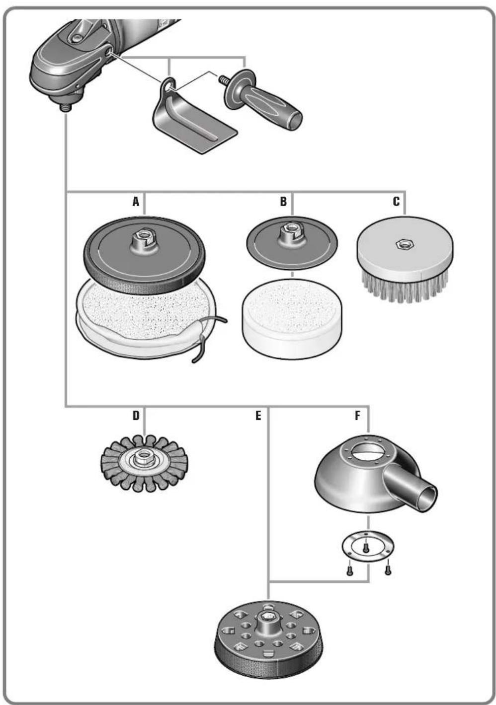
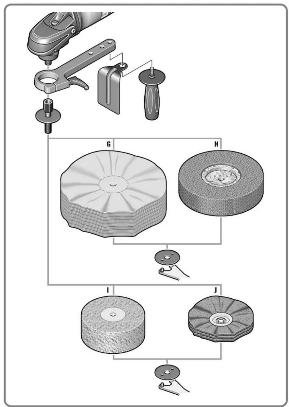
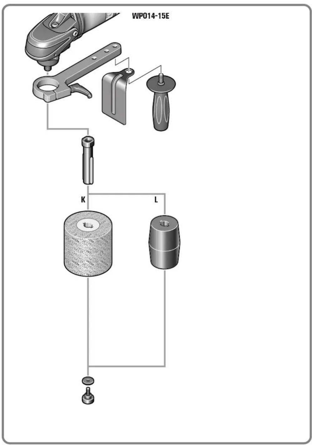
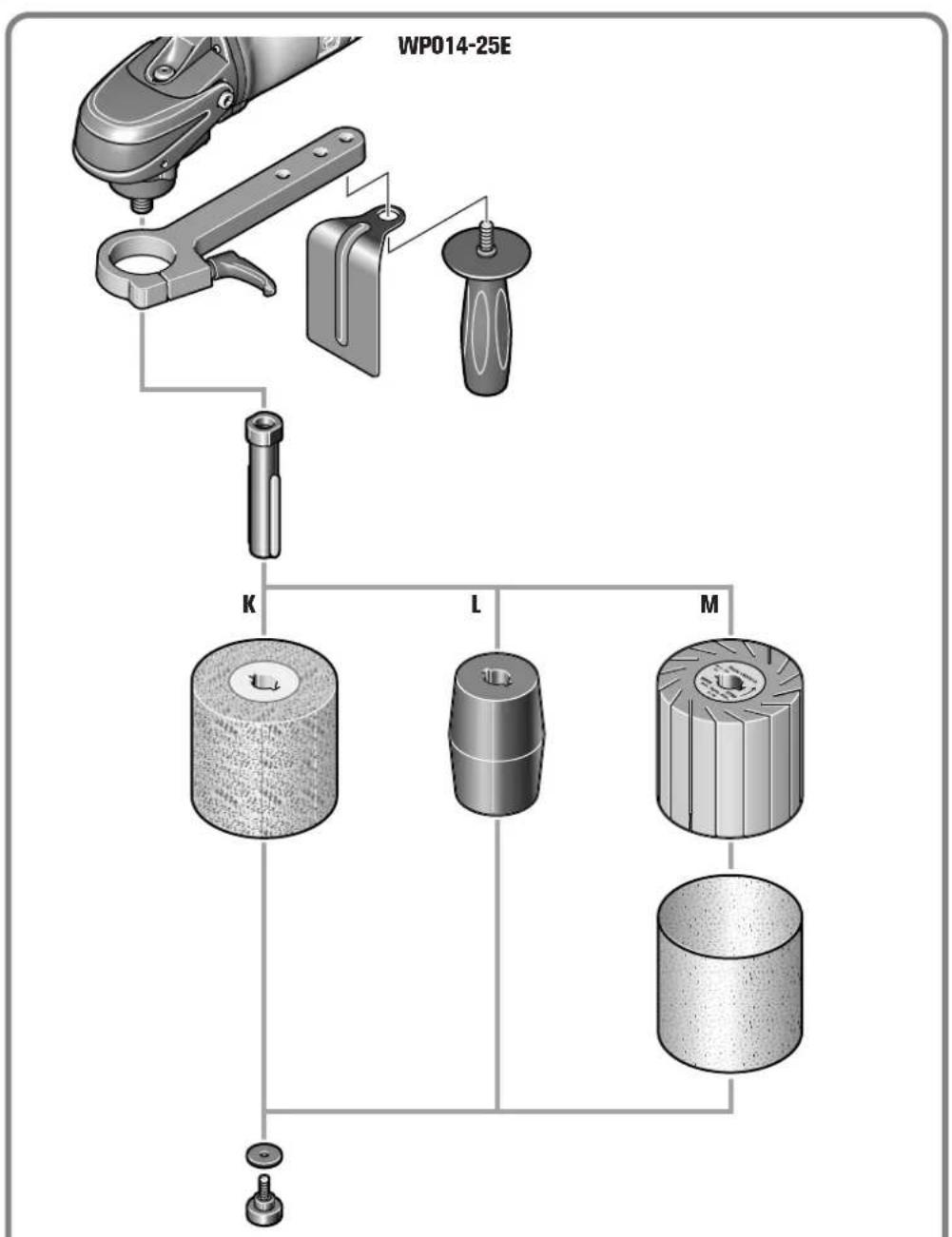
Selection of accessories
(see pages 8 - 11).
Use only original FEIN accessories. The accessories must be intended for the power tool type.
Use accessories A-M with the safety guard mounted.
A Backing pad for lambskin with tensioning cord
B Backing pad with Velcro, Velcro sanding sheets, sanding fleece with Velcro attachment, lambskin
C Cup brush
D Steel wire brush
E Sanding plate
F Extraction hood
G Nettle buffer/Flannel buffer
H Abrasive fleece wheel
I Polishing wheel (felt)
J Sanding fleece, polishing rings
K Elastic sanding cylinder, lamella fleece cylinder
L Sanding strip roll
M Expanding roll for sanding sleeves


Notice originale.
Miljøvern, deponering.
natural_image
Pure geometric diagram with crosshair and circular shapes, no text or symbols presentja
サンディングにおける安全注意事項
A ∪ ∪ ∪ ∪ ∪ ∪ ∪ ∪ ∪ ∪ ∪ ∪ ∪ ∪ ∪ ∪ ∪ ∪ ∪ ∪ ∪ ∪ ∪ ∪ ∪ ∪ ∪ ∪ ∪ ∪ ∪ ∪ ∪ ∪ ∪ ∪ ∪ ∪ ∪ ∪ ∪ ∪ ∪ ∪ ∪ ∪ ∪ ∪ ∪ ∪ ∮