
SLE 200 B2 - Dehumidifier SILVERCREST - Free user manual and instructions
Find the device manual for free SLE 200 B2 SILVERCREST in PDF.
| Product Type | Dehumidifier |
| Brand | SilverCrest |
| Model | SLE 200 B2 |
| Dimensions (W x H x D) | Approx. 40.6 x 27.0 x 20.5 cm |
| Weight | Approx. 8.5 kg |
| Power Supply | 220-240 V ~, 50 Hz, 245 W |
| Rated Current | 1.4 A |
| Airflow Rate | 100 m³/h |
| Water Tank Capacity | Approx. 2.1 l |
| Dehumidification Capacity (24 h) | 10 l at 30 °C / 80 % RH; 5 l at 27 °C / 60 % RH |
| Recommended Room Area | Max. 16 m² (40 m³) |
| Operating Temperature | 5 to 32 °C |
| Refrigerant | R290 (propane), 35 g |
| Main Functions | Dehumidification, laundry drying, timer 1-24 h, auto defrost, overheat protection |
| Filter Maintenance | Clean every 15 days; washable with lukewarm water |
| Tank Maintenance | Clean every 2 weeks with dish soap |
| Drain Hose | Possible with hose or garden hose adapter |
| Safety | Auto shut-off when tank full, overheat protection, auto defrost |
| Warranty | 3 years (France and Belgium) |
| Included Accessories | Hose, garden hose adapter, 4 castors, instruction manual |
| Recycling | Appliance, refrigerant and packaging recyclable (collection points) |
Frequently Asked Questions - SLE 200 B2 SILVERCREST
User questions about SLE 200 B2 SILVERCREST
0 question about this device. Answer the ones you know or ask your own.
Ask a new question about this device
Download the instructions for your Dehumidifier in PDF format for free! Find your manual SLE 200 B2 - SILVERCREST and take your electronic device back in hand. On this page are published all the documents necessary for the use of your device. SLE 200 B2 by SILVERCREST.
USER MANUAL SLE 200 B2 SILVERCREST
natural_image
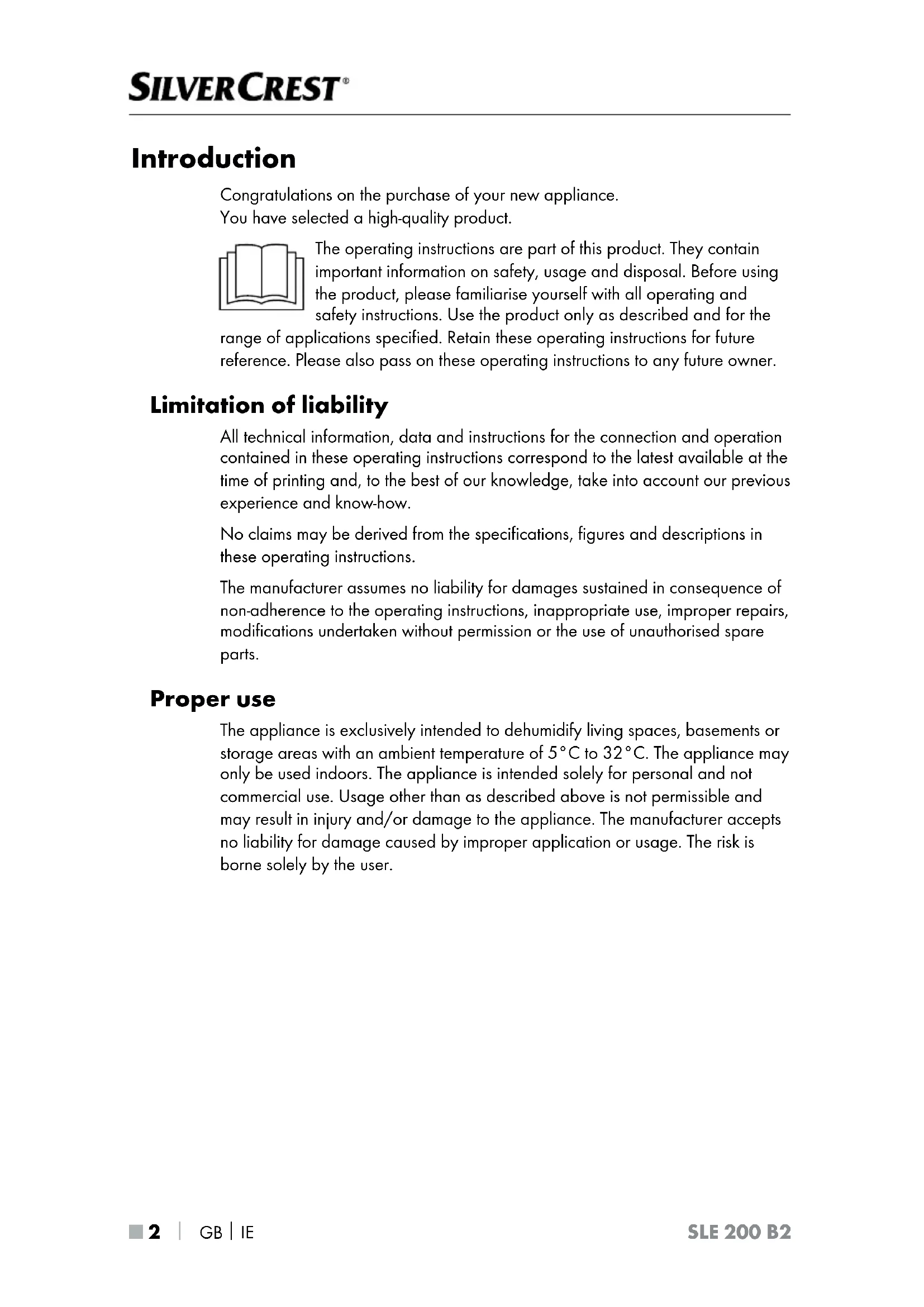
White portable air purifier with ventilation grilles and control panel (no visible text or symbols)DEHUMIDIFIER / LUFTENTFEUCHTER DÉSHUMIDIFICATEUR D'AIR SLE 200 B2
GB IE
DEHUMIDIFIER
Operating instructions
FR BE
DÉSHUMIDIFICATEUR D'AIR
Mode d'emploi
CZ
ODVLHČOVAČ VZDUCHU
Návod k obsluze
SK
ODVLHČOVAČ VZDUCHU
Návod na obsluhu
DK
LUFTAFFUGTER
GB/IE Operating instructions Page 1
Limitation of liability 2
Proper use 2
Warnings and symbols used .... 3
Safety information 4
Basic safety instructions 6
Package contents and transport inspection 9
Appliance description 10
Using the appliance ....1 1
Before initial use 11
Electrical connection 11
Guidelines for operation 11
Automatic defrosting 11
Protection against overheating 12
Assembly 12
Transport ....12
Handling and use 13
Switching the appliance on/off 13
Operating status displays 14
Selecting programmes 14
Timer function 15
Emptying the water tank 16
Hose drainage 17
Cleaning 18
Cleaning the appliance 18
Cleaning the filter 19
Storage 19
Troubleshooting 20
Disposal 21
Disposal of the appliance 21
Disposal of the refrigerant 21
Disposal of the packaging 21
Appendix 22
Technical data 22
Notes on the EU Declaration of Conformity 2 2
Kompernass Handels GmbH warranty 23
Service 24
Importer 24
Introduction
Congratulations on the purchase of your new appliance.
You have selected a high-quality product.

The operating instructions are part of this product. They contain important information on safety, usage and disposal. Before using the product, please familiarise yourself with all operating and safety instructions. Use the product only as described and for the range of applications specified. Retain these operating instructions for future reference. Please also pass on these operating instructions to any future owner.
Limitation of liability
All technical information, data and instructions for the connection and operation contained in these operating instructions correspond to the latest available at the time of printing and, to the best of our knowledge, take into account our previous experience and know-how.
No claims may be derived from the specifications, figures and descriptions in these operating instructions.
The manufacturer assumes no liability for damages sustained in consequence of non-adherence to the operating instructions, inappropriate use, improper repairs, modifications undertaken without permission or the use of unauthorised spare parts.
Proper use
The appliance is exclusively intended to dehumidify living spaces, basements or storage areas with an ambient temperature of 5^ C to 32^ C. The appliance may only be used indoors. The appliance is intended solely for personal and not commercial use. Usage other than as described above is not permissible and may result in injury and/or damage to the appliance. The manufacturer accepts no liability for damage caused by improper application or usage. The risk is borne solely by the user.
Warnings and symbols used
The following warnings and symbols are used in these operating instructions, on the packaging and on the appliance (where applicable):
 | DANGER! A warning with this symbol and the signal word "DANGER" indicates an imminently hazardous situation that will result in death or serious injury if not avoided. |
 | WARNING! A warning with this symbol and the signal word "WARNING" indicates a potentially hazardous situation that could result in death or serious injury if not avoided. |
 | CAUTION! A warning with this symbol and the signal word "CAUTION" indicates a potentially hazardous situation that could result in a minor or moderate injury if not avoided. |
 | ATTENTION! A warning with this symbol and the signal word "ATTENTION" indicates a potential situation that could result in property damage if not avoided. |
 | Note: A note identifies additional information that facilitates the use of the appliance. |
 | AC current/voltage |
 | Caution! Risk of fire! |
 | Observe operating instructions |
| [i] | Instruction manual, operating instructions |
 | Service indicator, refer to the operating instructions |
Safety information
⚠️ DANGER! Risk of fatal injury from electrocution!
Contact with live cables or components can result in a fatal injury!
Please observe the following safety guidelines to prevent electrical hazards.
■ Do not use the appliance if the power cable or the plug is damaged.
■ There is a risk of electrocution if live connections are touched and the electrical and mechanical structure is changed.
■ Do not place the appliance in water, in water pooling areas or puddles.
■ Never operate the appliance near a bath tub, a shower, a filled wash basin or similar structures.
■ Do not immerse appliance, the cabling or the mains plug in water or other fluids.
■ Protect the appliance from water droplets or spray.
In the event that liquid enters the appliance (apart from in the water tank), disconnect the mains plug immediately. Arrange to have the appliance checked before using it again.
■ Do not handle the appliance with damp hands.
■ If the appliance falls into water, disconnect the mains plug immediately. Do not attempt to remove the appliance before you have done so.
Danger of explosion! Risk of fire!
■ Do not use the appliance in a potentially explosive environment containing combustible liquids, gases or dusts. Electrical appliances generate sparks that can ignite the dust or fumes.
■ The appliance contains extremely flammable gas under pressure that may explode if heated.
- Keep the appliance away from heat, hot surfaces, sparks, naked flames and other sources of ignition. Do not smoke.
■ Do not use any items other than those permitted by the manufacturer to speed up the defrosting process.
■ The appliance may only be stored in rooms without permanent sources of ignition (e.g. open flames, a switched-on gas appliance or an electric heater).
■ Do not drill or burn.
■ Remember that refrigerants are odourless.
Risk of disease!
■ The collected water is not suitable for drinking or watering plants. There are potential health hazards.
! ATTENTION! Property damage!
■ Do not use the appliance in swimming pools, wash rooms or similar facilities.
■ The appliance is not suitable for drying lagging. If insulation or lagging materials are damp following a pipe burst, consult an expert.
■ Never expose the appliance to temperatures of 0^ C or lower. Residual water in the lines could freeze and damage the system.
■ Do not use the appliance in a dusty or chlorinated environment.
Basic safety instructions
To ensure safe operation of the appliance, follow the safety guidelines set out below:
■ Check the appliance for visible external damage before use. Do not use an appliance that has been damaged or dropped.
■ To avoid potential risks, damaged mains cables should be replaced by the manufacturer, its customer service department or a similarly qualified person.
■ Do not operate the appliance outdoors.
■ During operation, always keep windows and doors closed so that the appliance can work effectively.
■ Do not operate the appliance in the proximity of highly inflammable gases or materials, near naked flames or in areas prone to oil and water splashing.
This appliance may be used by children aged 8 years and above and by persons with limited physical, sensory or mental capabilities or lack of experience and knowledge, provided that they are under supervision or have been told how to use the appliance safely and are aware of the potential risks. Do not allow children to use the appliance as a toy. Cleaning and user maintenance tasks may not be carried out by children unless under supervision.
■ All repairs must be carried out by authorised specialist companies or by the Customer Service department. Improper repairs can pose significant risks to the user. It will also invalidate any warranty claims.
■ Do not expose the appliance to rain. Protect the appliance against moisture and the ingress of fluids and objects into the casing. Never immerse the appliance in water and do not place objects containing fluids (e.g. vases) on the appliance. The appliance could be irreparably damaged!
■ Do not place heavy objects on the appliance.
■ Do not cover the appliance (e.g. with newspapers, cushions or blankets).
■ Do not insert any objects into the ventilation slits.
■ Avoid direct sunlight.
■ Do not place any naked flames, e.g. burning candles, on or directly next to the appliance.
In the event of malfunctions, and in bad weather, disconnect the plug from the mains power socket.
■ Ensure that the air inlet and air outlet opening remain free of soiling during operation. Never cover the appliance!
■ Always place the appliance on a solid, flat surface so that it cannot tip over.
- Do not permanently install the appliance. Position the appliance so that its side panels have a clearance of at least 20 cm from walls or other objects and ensure a clearance of at least 30 cm from the front, rear and top panels of the appliance in order to ensure good air circulation. Take care not to obstruct the air inlet and outlet opening.
■ The appliance may only be operated in rooms with an ambient temperature of 5^ C to 32^ C.
■ Use the appliance only in rooms up to 16 m².
■ The appliance must be installed, operated and stored in a room with a floor area greater than 4 m^2 .
If the appliance is operated in unventilated areas, these must be designed in such a way that the refrigerant cannot accumulate anywhere in the event of refrigerant leakage. Otherwise, a combustible mixture may be formed.
■ The appliance may only be stored in rooms without permanent sources of ignition (e.g. open flames, a switched-on gas appliance or an electric heater).
■ The appliance must be stored in a way that does not damage it.
■ Clean the air filter before it becomes heavily soiled.
■ While draining via a hose, ensure that it does not become blocked and that the open end of the hose is positioned at a lower level than the outlet aperture. The end of the hose must be positioned above a drain.
■ Operate the appliance only together with the water tank or with the hose installed.
■ Connect the safety plug only to a properly installed, easily accessible plug socket with protected contacts, the voltage of which corresponds to the specifications on the rating plate. The plug socket must remain easily accessible even after connection.
■ Before cleaning, always disconnect the mains plug from the mains power socket.
■ Always transport, operate and store the appliance up-right! The water tank must be emptied before transport.
■ Never pull the device by the power cable when transporting it on its casters.
Package contents and transport inspection
The appliance is supplied with the following components as standard:
- Dehumidifier
- Hose
• EU garden hose adapter
• 4 transport casters
• These operating instructions
i Note
▶ Check the package for completeness and signs of visible damage.
▶ If the delivery is incomplete or damage has occurred as a result of defective packaging or during transport, contact the Service hotline (see section Service).
◆ Remove all packaging materials and all carriage braces from the appliance
◆ Remove the film from the control panel.
Appliance description
(See fold-out page for illustrations)
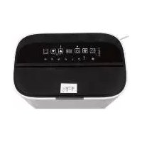
① Control panel
② Air inlet grille
3 Air filter
4 Water tank
⑤ Fill level indicator
6 Transport casters (4x)
⑦ Carrying handle
8 Air outlet
9 Stopper
⑩ Water outlet opening
11 Cable retainer
12 Power cable with mains plug
⑬ MODE button
14 DEHUMIDIFICATION LED
15 DRY LAUNDRY LED
16 DOWN button
17 AUTO DE-ICING LED
18 TIMER LED
19 WATER TANK FULL LED
20 Display (timer/humidity)
21 + UP button
22 STANDBY button
23 Hose
24 EU garden hose adapter
Using the appliance
Before initial use
◆ Place the appliance on a flat, dry and solid surface.
Allow the appliance to remain in the usage position for approx. 30 minutes so that the coolant can settle.
◆ Check that the water tan ^4 is correctly inserted.
◆ Insert the plug12 into a mains power socket.
Electrical connection
! ATTENTION!
▶ Before connecting the appliance, compare the specifications for the required input voltage on the rating plate with the intended voltage source for operation. This data must agree so that the appliance is not damaged.
The power cable must always be easily accessible, so that the appliance can be quickly removed from the mains in the event of an emergency.
▶ Check whether the power cable is undamaged and that it is not routed over hot surfaces and/or sharp edges, otherwise it will become damaged.
▶ Ensure that the power cab12 is not taut or kinked.
Guidelines for operation
If the air in your living spaces is constantly excessively humid, the cause should be identified and addressed. (Sustained - year-round - dehumidifying is generally not a good idea.)
The optimal ambient temperature for dehumidifying the air is 5^ C to 32^ C. Using a dehumidifier at temperatures below 5^ C is redundant, as there is little humidity in the air.
During operation, room temperature can increase by between 1°C and 4°C, depending on the size of the room. This is normal.
Automatic defrosting
To ensure that the appliance does not ice up during sustained operation, it defrosts automatically. The defrosting function is activated automatically and cannot be switched on manually. The appliance cannot be switched off during defrosting. During defrosting, the ⚙️ AUTO DE-ICING LED ⑰ lights up. The lower the ambient temperature at which the appliance is operated, the earlier or more often the automatic defrosting is activated. Once the defrosting process is complete, the appliance resumes operation in the previous selected settings.
Protection against overheating
The appliance has an overheating protection. It switches off automatically if there is a risk of overheating and switches back on once the appliance has fully cooled down. The appliance cannot be used during the cool-down phase.
Check whether external conditions may have triggered the overheating protection (e.g. temperatures above 32^ C or a blockage to the air outlet 8).
Assembly

WARNING!
▶ Do not connect the appliance to a power socket during assembly.
◆ Lay the appliance flat on its side on the floor.
◆ Press the castors ⑥ into the four holes on the bottom of the appliance until they fully click into place (see fig. 1).
natural_image
Pure schematic diagram of a heat exchanger or cooling unit with inlet/outlet ports and internal grid structure (no text or symbols)Fig. 1
◆ Place the appliance on the castors ⑥ after fitting them.
Transport

ATTENTION!
▶ Never pull the appliance by the power cable ^12 when transporting it on its castors ⑥.
▶ Use the castors ⑥ only on even surfaces. Do not roll the appliance over shag-pile carpets (e.g. flokati, tufted). These could block the castors ⑥.
◆ Use the castors ⑥ to move the appliance over even surfaces.
◆ Always hold the appliance by the carrying handle ⑦ when transporting it.
Handling and use
Switching the appliance on/off
Press the ⏻ STANDBY button 22 to switch on the appliance. You will hear a beep and the ⏻ DEHUMIDIFICATION LED 14 or the 15 DRY LAUNDRY LED 15 lights up permanently.
◆ Press the STANDBY button 22 to switch off the appliance. You will hear a beep and the DEHUMIDIFICATION LED 14 or the DRY LAUNDRY LED 15 goes out.
i Note
- The appliance always starts up with the last-selected setting. - If the appliance shuts down due to a power failure, it will automatically restart with the last-selected setting when power is restored.
If a timer has been programmed, the appliance switches off permanently after the specified time has elapsed (1–24 hours).
If the relative humidity value has been set in the DEHUMIDIFICATION program, the appliance switches off as soon as the value is reached. If the value is exceeded, the appliance switches back on again.
When the water tank 4 is full or removed, dehumidification stops. The fan continues to run for approx. 3 minutes and then switches off. If the water tank 4 has been removed or is not correctly inserted, the WATER TANK FULL 19 lights up. If switched on, the appliance will also beep for approx. 20 seconds.
i Note
The water tan ^4 must be completely inserted into the appliance, otherwise the condensation water cannot be properly collected.
Operating status displays
The different operating states are shown on the control panel ① via LEDs and the display ②0:
LED indicators
| LED lit Meaning | |
| [35X0] WATER TANK FULL 19 | The water tank 4 is full or not inserted. |
| [WSTZ] TIMER 18 | A switch-off time has been activated. |
 DEHUMIDIFICATION 14 DEHUMIDIFICATION 14 | Shows the selected programme. |
 DRY LAUNDRY 15 DRY LAUNDRY 15 | |
| [36SA] AUTO DE-ICING 17 | Automatic defrosting is activated. |
Display indicator
| Display Meaning | |
 | During operation, the current relative humidity value is permanently displayed in %. |
i Note
▶ Note that the values for the relative humidity have a tolerance of approx. ± 3 %, and switching on the appliance or dehumidification may be slightly delayed.
Selecting programmes
The appliance has two distinct programmes:
DEHUMIDIFICATION
DRY LAUNDRY
Press the MODE button 13 repeatedly to select the desired programme. The DEHUMIDIFICATION LED 14 or the DRY LAUNDRY LED 15 lights up.
DEHUMIDIFICATION
This programme offers you the option of setting the desired air humidity level that should be achieved yourself.
Press the + UP button 21 or the - DOWN button 16 to set the desired humidity in 5% steps between 30% and 80%. The set value flashes on the display 20 for approx. 5 seconds and then the current relative humidity value is shown again.
Additionally, you also have the option to select the setting if you want to make a setting below 30% relative humidity. This setting allows you to achieve a very low humidity as the dehumidification runs permanently.
i Note
The minimum humidity that can be achieved in 60 mode is dependent on many factors, such as the room size or the ambient temperature, etc. Therefore, it is not possible to define a generally applicable minimum value.
DRY LAUNDRY
You can use this programme to dry damp laundry or textiles faster. Turn the appliance so that the air flow from the air outlet ⑧ is directed towards the garments you want to dry. Changes in the desired humidity are not possible in this programme.
Timer function
The appliance is equipped with a timer function that can be activated for both programmes. One of 24 switch-off times, ranging from 1 to 24 hours, can be selected. Once the set time has elapsed, the appliance switches off permanently.
While the appliance is running, press the UP button 21 and the — DOWN button 16 at the same time. The TIMER LED 18 lights up, and flashes on the display 20.
- Press the UP button 21 or the —DOWN button 16 to set a switch-off time from 1 to 24 hours. The selected switch-off time flashes on the display 20 for approx. 5 seconds and then the current relative humidity value is displayed again.
To stop the timer prematurely, press the UP button 21 and the — DOWN button 16 at the same time again. Then press the + UP button 21 or the — DOWN button 16 to set the timer to 00. After around 5 seconds, the TIMER LED 18 goes out and the display 20 shows the current relative humidity value.
Emptying the water tank
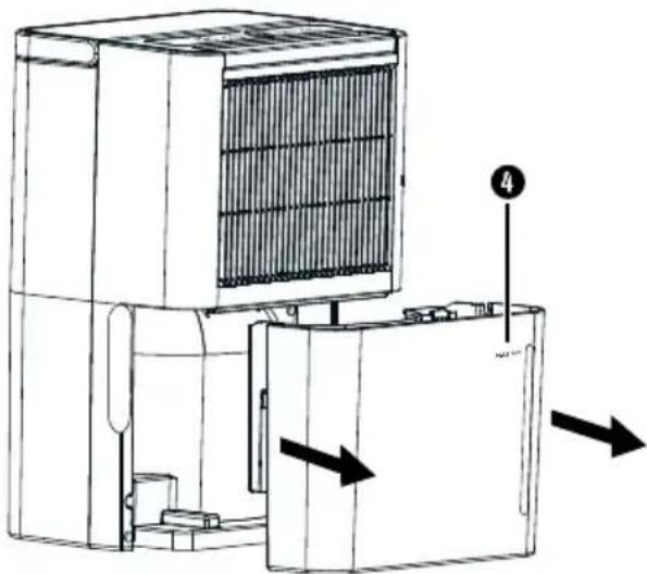
The water tank ④ has a capacity of approx. 2.1 litres. The water level can be checked by means of the fill level indicator ⑤. The appliance can only be operated with the water tank ④ inserted. When the water tank ④ is full, the WATER TANK FULL LED ⑲ lights up. In addition, the appliance will also beep for approx. 20 seconds. The dehumidification stops; the fan continues to run for approx. 3 minutes and then switches itself off.
◆ Carefully pull the water tank ④ out of the appliance using the recessed grips on the side (see figure 2).
natural_image
Technical line drawing of a mechanical device with internal components and directional arrows indicating movement (no text or symbols)Fig. 2
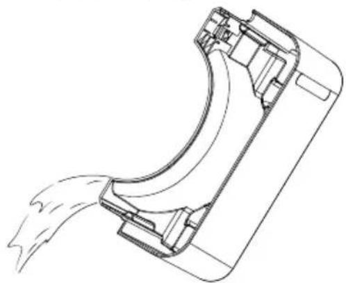
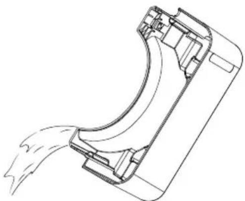
Empty the water tank ④ into a sink (see figure 3) and replace the water tank ④ in the appliance. The appliance resumes operation with the previously selected programme.
natural_image
Technical line drawing of a mechanical component with fluid flow, no text or symbols presentFig. 3
Hose drainage
In very humid rooms, it often makes more sense to drain off the water directly via a hose rather than collect it in the water tank ④. You can use the supplied hose ②3 or the EU garden hose adapter ②4 to set up a permanent drainage outlet.
! ATTENTION!
- When draining via the hose, the appliance runs continuously. When draining via the hose, make sure that it is not kinked and that it runs downwards along the entire length. Otherwise, the water may flow back into the appliance and damage it.
▶ Check the entire connection system regularly for leaks.
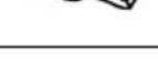
◆ Remove the stopper⑨ from the water outlet opening ⑩.
Connect either the supplied hose ^23 or the EU garden hose adapter ^24 to the water outlet opening ^10 (see figures 4 and 5).
When using the EU garden hose adapter ^24 , screw a garden hose onto the EU garden hose adapter ^24 (see figure 5).
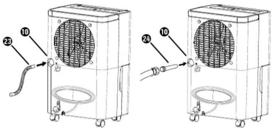
Fig. 4 Fig. 5
ATTENTION!
▶ Screw the EU garden hose adapte ^24 hand-tight only. Do not use a wrench as this may damage the EU garden hose adapter ^24 .
i Note
▶ Depending on the garden hose system you use, you may need an additional adapter. These are available from specialist stores.
- Set up the appliance so that the end of the hose is positioned over a drain. The open end of the hose must lie below the water outlet opening ⑩ of the appliance (i.e. the hose must have a downwards gradient).
Cleaning
Cleaning the appliance
! ATTENTION!
▶ Do not allow any liquids or moisture to get into the appliance.
▶ To avoid irreparable damage to the appliance, never immerse it in water.
▶ Always remove the mains plus 2 from the mains power socket before cleaning the appliance.
▶ Do not use aggressive or abrasive cleaning agents, as these may corrode the surface of the casing.
▶ Do not clean the water tanl ^4 in the dishwasher. Otherwise, it will be damaged.
If required, wipe the casing with a slightly damp cloth.
Remove the water tank and pour the water into a sink. Dry the water tank well inside and outside before replacing it in the appliance.
We recommend cleaning the water tan regularly (every two weeks) to prevent mould and bacteria. Fill the water tank with lukewarm water and add a commercially available detergent. Rinse repeatedly with lukewarm water. We also recommend disinfection following cleaning. To do this, use a standard commercial, alcohol-based disinfecting agent or high-proof alcohol. Both substances are completely harmless if rinsed repeatedly with lukewarm water afterwards.
Remove any accumulations of dust on the air inlet grille and the air outlet grille with a paintbrush, soft brush or a vacuum cleaner.
Cleaning the filter
The performance of the appliance also depends upon how clean the filter is. The air filter ③ should be cleaned every 2 weeks.
The air filter ③ is located behind the air inlet grille ②. Take hold of the grip edge of air filter ③ with your fingers and pull it upwards out of the appliance (see figure 6).

natural_image
Line drawing of a multi-tiered refrigerator with ventilation grilles and an upward arrow indicator (no text or symbols)Fig. 6
◆ Vacuum the air filter ③ or clean it with a soft brush. If the air filter ③ is very dirty, wash it in lukewarm water.
Allow the air filter ③ to dry out completely before replacing it in the appliance.
Storage
◆ Remove the plug 12 from the mains power socket.
◆ Wind the power cable ⑫ around the cable retainer ⑪ on the rear of the appliance.
◆ Empty the water tank ④ if you are not going to use the appliance for a long time.
◆ Always store the appliance in an upright position and in a dry and dust-free environment without direct sunlight.
Troubleshooting
The following table will help you to identify and rectify minor malfunctions. If the solutions below do not resolve the problem, please contact Customer Service (see section Service).
| Fault Possible cause Remedy | ||
| The appliance will not switch on. | The plug 12 is not plugged in. | Insert the plug 12 into the mains power socket. |
| The mains power socket is not supplying power. | Check the house mains fuse. | |
| Safety stop due to missing or incorrectly inserted water tank 4 | Insert the water tank 4 correctly. | |
| The water tank 4 is full. | Empty the water tank 4 and reinsert it. | |
| The appliance stops occasionally (the fan switches off). | The automatic defrosting function is activated. | This is a normal feature of the appliance. |
| The humidity of the room has reached the desired level. | This is a normal feature of the appliance. | |
| The appliance is producing no or too little condensate. | The air inlet (air inlet grille 2) or air outlet 8 openings are contaminated or blocked. | Ensure that the air inlet (air inlet grille 2) and air outlet 8 openings are clean and free of obstructions. |
| The room's windows and doors are open. | Close the windows and doors. | |
| The air ejected is warm. | Heat exchange process | This is a normal feature of the appliance. |
| The error code E 1 flashes on the display 20 | Temperature sensor error/ humidity sensor error | Contact the Customer Service department (see section Service). |
Disposal
Applies only to France:

The product, its packaging and the operating instructions are recyclable. They are subject to an extended manufacturer responsibility and will be collected separately.
Disposal of the appliance
The adjacent symbol of a crossed-out dustbin means that this appliance is subject to Directive 2012/19/EU. This directive states that this appliance may not be disposed of in the normal household waste at the end of its useful life, but must be taken to specially set-up collection locations, recycling depots or disposal companies.
The disposal is free of charge for the user. Protect the environment and dispose of this appliance properly.
If your old appliance has stored any personal data, you are responsible for deleting it yourself before returning it.

Your local community or municipal authorities can provide information on how to dispose of the worn-out product.
Disposal of the refrigerant
This appliance contains R290 (propane) as a refrigerant. The system is hermeticallysealed.
The undamaged refrigerant must be disposed of professionally. Please contact your waste disposal facility if you are in any doubt.
Disposal of the packaging
The packaging materials have been selected for their environmental friendliness and ease of disposal and are therefore recyclable. Dispose of packaging materials that are no longer needed in accordance with applicable local regulations. Dispose of the packaging in an environmentally friendly manner. Note the labelling on the packaging and separate the packaging material components for disposal, if necessary. The packaging material is labelled with abbreviations (a) and numbers (b) with the following meanings: 1-7: plastics, 20-22: paper and cardboard, 80-98: composites.

Appendix
Technical data
| Input voltage 220-240 V~, 50 Hz | |
| Input power 245 W (at 32°C/90% rh) | |
| Nominal current 1.4 A (at 32°C/90% rh) | |
| Air flow rate 100 m3/h | |
| Water tank approx. 2.1 l | |
| Intake pressure 1.2 MPa | |
| Discharge pressure 2.5 MPa | |
| Dehumidification performance/24 h* | 10 l (at 30°C/80% rh)5 l (at 27°C/60% rh) |
| Recommended room size | approx. 16 m2 or approx. 40 m3(at a ceiling height of 2.5 m) |
| Refrigerant R290 | |
| Fill level 35 g | |
| Operating temperature 5°C to 32°C | |
| Dimensions approx. 40.6 x 27.0 x 20.5 cm | |
| Weight approx. 8.5 kg |
* The lower the ambient temperature and the colder the temperature outside becomes, the less moisture accumulates in the air and flows from outside into the room to be dehumidified. For this reason, dehumidification performance steadily decreases when temperatures drop and can come to a standstill. This does not mean that the appliance is defective.
Notes on the EU Declaration of Conformity

In terms of compliance with fundamental specifications and other relevant regulations, this appliance complies with the directive 2014/35/EU, the directive 2014/30/EU and the directive 2009/125/EC.
The complete EU Declaration of Conformity is available from the importer.
This appliance has a 3-year warranty valid from the date of purchase. If this product has any faults, you, the buyer, have certain statutory rights. Your statutory rights are not restricted in any way by the warranty described below.
Warranty conditions
The warranty period starts on the date of purchase. Please keep your receipt in a safe place. This will be required as proof of purchase.
If any material or manufacturing fault occurs within three years of the date of purchase of the product, we will either repair or replace the product for you or refund the purchase price (at our discretion). This warranty service requires that you present the defective appliance and the proof of purchase (receipt) within the three-year warranty period, along with a brief written description of the fault and of when it occurred.
If the defect is covered by the warranty, your product will either be repaired or replaced by us. The repair or replacement of a product does not signify the beginning of a new warranty period.
Warranty period and statutory claims for defects
The warranty period is not prolonged by repairs effected under the warranty. This also applies to replaced and repaired components. Any damage and defects present at the time of purchase must be reported immediately after unpacking. Repairs carried out after expiry of the warranty period shall be subject to a fee.
Scope of the warranty
This appliance has been manufactured in accordance with strict quality guidelines and inspected meticulously prior to delivery.
The warranty covers material faults or production faults. The warranty does not extend to product parts subject to normal wear and tear or to fragile parts which could be considered as consumable parts such as switches, batteries or parts made of glass.
The warranty does not apply if the product has been damaged, improperly used or improperly maintained. The directions in the operating instructions for the product regarding proper use of the product are to be strictly followed. Uses and actions that are discouraged in the operating instructions or which are warned against must be avoided.
This product is intended solely for private use and not for commercial purposes. The warranty shall be deemed void in cases of misuse or improper handling, use of force and modifications / repairs which have not been carried out by one of our authorised Service centres.
Warranty claim procedure
To ensure quick processing of your case, please observe the following instructions:
■ Please have the till receipt and the item number (IAN) 415717_2210 available as proof of purchase.
■ You will find the item number on the type plate on the product, an engraving on the product, on the front page of the operating instructions (below left) or on the sticker on the rear or bottom of the product.
If functional or other defects occur, please contact the service department listed either by telephone or by e-mail.
■ You can return a defective product to us free of charge to the service address that will be provided to you. Ensure that you enclose the proof of purchase (till receipt) and information about what the defect is and when it occurred.
You can download these instructions along with many other manuals, product videos and installation software at www.lidl-service.com.
This QR code will take you directly to the Lidl service page (www.lidl-service.com) where you can open your operating instructions by entering the item number (IAN) 415717_2210.
Service
GB Service Great Britain
Tel.: 0800 404 7657
E-Mail: kompernass@lidl.co.uk
IE ServiceIreland
Tel.: 1800 101010
E-Mail: kompernass@lidl.ie
IAN 415717_2210
Importer
Please note that the following address is not the service address. Please use the service address provided in the operating instructions.
KOMPERNASS HANDELS GMBH
BURGSTRASSE 21
44867 BOCHUM
GERMANY
www.kompernass.com
Inhaltsverzeichnis
Einführung 26
natural_image
Pure schematic diagram of a heat exchanger or cooling unit with inlet/outlet ports and internal grid structure (no text or symbols)Abb. 1
natural_image
Technical line drawing of a mechanical device with internal components and directional arrows indicating movement (no text or symbols)Abb. 2
natural_image
Technical line drawing of a mechanical component with fluid flow, no text or symbols presentAbb. 3
Abb. 4 Abb. 5
! ACHTUNG!
natural_image
Line drawing of a multi-tiered air conditioner unit with labeled components (no text or symbols)Abb. 6
KOMPERNASS HANDELS GMBH
BURGSTRASSE 21
44867 BOCHUM
DEUTSCHLAND
www.kompernass.com
Table des matières
Introduction 52
natural_image
Pure schematic diagram of a heat exchanger or cooling unit with inlet/outlet ports and internal grid structure (no text or symbols)Fig. 1
natural_image
Technical line drawing of an air conditioner unit with cooling panel and door, showing airflow direction (no text or symbols)Fig. 2
natural_image
Technical line drawing of a mechanical component with fluid flow, no text or symbols presentFig. 3
Fig. 4 Fig. 5
① ATTENTION!
natural_image
Line drawing of a multi-tiered industrial machine with a central rack and upward arrow (no text or symbols)Fig. 6
KOMPERNASS HANDELS GMBH
BURGSTRASSE 21
44867 BOCHUM
ALLEMAGNE
www.kompernass.com
Inhoud
Inleiding 80
natural_image
Pure technical diagram of a heat exchanger or cooling unit with inlet/outlet ports and internal grid structure (no text or symbols)Afb. 1
natural_image
Technical line drawing of an air conditioner unit with cooling panel and door, showing airflow direction (no text or symbols)Afb. 2
natural_image
Technical line drawing of a mechanical component with fluid flow, no text or symbols presentAfb. 3
Drainage met slang
Afb. 4 Afb. 5
LETOP!
▶ Draai de EU-tuinslangadapte ^24 slechts handvast vast.
natural_image
Line drawing of a multi-tiered industrial machine with a vertical panel and upward arrow (no text or symbols)Abb. 6
KOMPERNASS HANDELS GMBH
BURGSTRASSE 21
44867 BOCHUM
DUITSLAND
www.kompernass.com
Obsah
Úvod....104
natural_image
Pure schematic diagram of a heat exchanger or cooling unit with inlet/outlet ports and internal grid structure (no text or symbols)Obr. 1
natural_image
Technical line drawing of a mechanical device with internal components and directional arrows indicating movement (no text or symbols)Obr. 2
natural_image
Technical line drawing of a mechanical component with fluid flow, no text or symbols presentObr. 3
Obr. 4 Obr. 5
! POZOR!
natural_image
Line drawing of a multi-tiered industrial machine with a top panel and side panel, showing internal structure and airflow direction (no text or symbols)Obr. 6
KOMPERNASS HANDELS GMBH
BURGSTRASSE 21
44867 BOCHUM
NĚMECKO
www.kompernass.com
Spis treści
W step 128
natural_image
Pure schematic diagram of a heat exchanger or cooling unit with inlet/outlet ports and internal grid structure (no text or symbols)Rys. 1
natural_image
Technical line drawing of a server or air conditioner unit with internal cooling panel and directional arrows indicating movement (no text or symbols)Rys. 2
natural_image
Technical line drawing of a mechanical component with fluid flow, no text or symbols presentRys. 3
Rys. 4 Rys. 5
! UWAGA!
natural_image
Line drawing of a multi-tiered industrial machine with a top panel and internal structure, no text or symbols present.Rys. 6
KOMPERNASS HANDELS GMBH
BURGSTRASSE 21
44867 BOCHUM
NIEMCY
www.kompernass.com
Obsah
Úvod....152
natural_image
Pure schematic diagram of a heat exchanger or cooling unit with inlet/outlet ports and internal grid structure (no text or symbols)Obr. 1
Po namontovaní kolieso 6 prístroj postavte na kolieska.
Preprava
! POZOR!
natural_image
Technical line drawing of a mechanical device with internal components and directional arrows indicating movement (no text or symbols)Obr. 2
natural_image
Technical line drawing of a mechanical component with fluid flow, no text or symbols presentObr. 3
Obr. 4 Obr. 5
! POZOR!
▶ EÚ adaptér na záhradnú hadic24 utiahnite iba pevne rukou.
natural_image
Line drawing of a multi-tiered industrial machine with a vertical panel and upward arrow (no text or symbols)Obr. 6
KOMPERNASS HANDELS GMBH
BURGSTRASSE 21
44867 BOCHUM
NEMECKO
www.kompernass.com
Índice
Introducción....176
natural_image
Pure schematic diagram of a heat exchanger or cooling unit with inlet/outlet ports and internal grid structure (no text or symbols)Fig. 1
natural_image
Technical line drawing of a mechanical device with internal components and directional arrows indicating movement (no text or symbols)Fig. 2
natural_image
Technical line drawing of a mechanical component with fluid flow, no text or symbols presentFig. 3
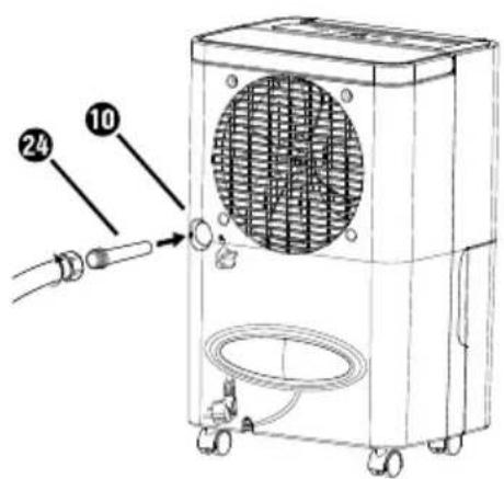
Fig. 4 Fig. 5
! ¡ATENCIÓN!
natural_image
Line drawing of a multi-tiered industrial machine with a central rack and upward arrow indicator (no text or symbols)Fig. 6
KOMPERNASS HANDELS GMBH
BURGSTRASSE 21
44867 BOCHUM
ALEMANIA
www.kompernass.com
Indholdsfortegnelse
Introduktion 200
natural_image
Pure schematic diagram of a heat exchanger or cooling unit with inlet/outlet ports and internal grid structure (no text or symbols)Fig. 1
natural_image
Technical line drawing of a mechanical device with internal components and directional arrows indicating movement (no text or symbols)Fig. 2
natural_image
Technical line drawing of a mechanical component with fluid flow, no text or symbols presentFig. 3
Dræning med slange
Fig. 4 Fig. 5
! OBS!
natural_image
Line drawing of a multi-tiered industrial machine with a top-mounted rack and ventilation unit (no text or symbols)Fig. 6
KOMPERNASS HANDELS GMBH
BURGSTRASSE 21
44867 BOCHUM
TYSKLAND
www.kompernass.com
Indice
Introduzione 224
natural_image
Pure schematic diagram of a heat exchanger or cooling unit with inlet/outlet ports and internal grid structure (no text or symbols)Fig. 1
natural_image
Technical line drawing of a mechanical device with internal components and directional arrows indicating movement (no text or symbols)Fig. 2
natural_image
Technical line drawing of a mechanical component with fluid flow, no text or symbols presentFig. 3
Fig. 4 Fig. 5
! ATTENZIONE!
natural_image
Line drawing of a multi-tiered refrigerator with ventilation grilles and an upward arrow indicator (no text or symbols)Fig. 6
KOMPERNASS HANDELS GMBH
BURGSTRASSE 21
44867 BOCHUM
GERMANIA
www.kompernass.com
Tartalomjegyzék
Bevezető 248
natural_image
Pure technical diagram showing a rectangular chamber with internal grid pattern and two circular components, no text or symbols present.- ábra
natural_image
Technical line drawing of a mechanical device with internal components and directional arrows indicating movement (no text or symbols)- ábra
natural_image
Technical line drawing of a mechanical component with no visible text or symbols- ábra
- ábra 5. ábra
! FIGYELEM!
natural_image
Line drawing of a multi-tiered industrial machine with a top panel and side panel, showing internal structure and airflow direction (no text or symbols)- ábra
natural_image
Pure technical diagram of a heat exchanger or cooling unit with inlet/outlet ports and internal grid structure (no text or symbols)Slika 1
natural_image
Technical line drawing of a mechanical device with internal components and directional arrows indicating movement (no text or symbols)Slika 2
natural_image
Technical line drawing of a mechanical component with fluid flow, no text or symbols presentSlika 3
Odvajanje vode s cevjo
Slika 4 Slika 5
! POZOR!
▶ EU-adapter za vrtno ce 24 zategnite samo z roko.
natural_image
Line drawing of a multi-tiered industrial air conditioner unit with ventilation grilles and top panel (no text or symbols)Slika 6
Zračni filter ③ posesajte ali ga očistite z mehko ščetko. Močno umazan zračni filter ③ operite z mlačno vodo.
Zračni filter ③ naj se v celoti posuši, preden ga znova vstavite v napravo.
Shranjevanje
KOMPERNASS HANDELS GMBH
BURGSTRASSE 21
44867 BOCHUM
NEMČIJA
www.kompernass.com
Pooblaščeni serviser
SI ServisSlovenija
Tel.: 080 080 917
E-Mail: kompernass@lidl.si
IAN 415717_2210
Garancijski list
Slika 1
Postavite uređaj na kotačiće 📄 nakon što ste ih montirali.
Transport
! POZOR!
▶ Uređaj nikada ne povlačite za mrežni kabel ⑫ kada ga prenosite na kotačićima ⑥.
Kotačiće ⑥ koristite samo na ravnim površinama. Ne kotrljajte uređaj po tepisima s duqim vlaknima (npr. flokati, rese). Isti mogu blokirati kotačiće ⑥.
♦ Koristite kotačiće ⑥ za transport uređaja na razini tla.
natural_image
Technical line drawing of a mechanical device with internal components and directional arrows indicating movement (no text or symbols)Slika 2
Ispraznite spremnik za vodu ④ u sudoper ili umivaonik (vidi sliku 3) i vratite spremnik za vodu ④ natrag u uređaj. Uređaj nastavlja rad s prethodno odabranim programom.
natural_image
Technical line drawing of a mechanical component with fluid flow, no text or symbols presentSlika 3
Slika 4 Slika 5
! POZOR!
natural_image
Line drawing of a multi-tiered refrigerator with ventilation grilles and an upward arrow indicator (no text or symbols)Slika 6
◆ Usisajte zračni filtar ③ ili ga očistite mekanom četkom. Ako je jako prljav, zračni filtar ③ operite mlakom vodom.
Zračni filtar ③ ostavite da se potpuno osuši, prije nego ga ponovno umetnete u uređaj.
Skladištenje
KOMPERNASS HANDELS GMBH
BURGSTRASSE 21
44867 BOCHUM
NJEMAČKA
www.kompernass.com
Cuprins
Introducere 320
natural_image
Pure schematic diagram of a heat exchanger or cooling unit with inlet/outlet ports and internal grid structure (no text or symbols)Fig. 1
natural_image
Technical line drawing of a mechanical device with internal components and directional arrows indicating movement (no text or symbols)Fig. 2
natural_image
Technical line drawing of a mechanical component with fluid flow, no text or symbols presentFig. 3
Scurgerea cu furtun

Fig. 4 Fig. 5
! ATENTIE!
natural_image
Line drawing of a multi-tiered refrigerator with ventilation grilles and an upward arrow indicator (no text or symbols)Fig. 6
KOMPERNASS HANDELS GMBH
BURGSTRASSE 21
44867 BOCHUM
GERMANIA
www.kompernass.com
Съдържание
Въведение....344
natural_image
Pure schematic diagram of a heat exchanger or cooling unit with inlet/outlet ports and internal grid structure (no text or symbols)Фиг. 1
natural_image
Technical line drawing of a server or air conditioner unit with cooling panel and directional arrows indicating airflow (no text or symbols)Фиг. 2
natural_image
Technical line drawing of a mechanical component with fluid flow, no text or symbols presentФиг. 3
Фиг. 4 Фиг. 5
! ВНИМАНИЕ!
natural_image
Line drawing of a multi-tiered refrigerator with ventilation grilles and an upward arrow indicator (no text or symbols)Фиг. 6
natural_image
Pure schematic diagram of a heat exchanger or cooling unit with inlet/outlet ports and internal grid structure (no text or symbols)Eik. 1
natural_image
Technical line drawing of a mechanical device with internal components and directional arrows indicating movement (no text or symbols)Eik. 2
natural_image
Technical line drawing of a mechanical component with fluid flow, no text or symbols presentEik. 3
Eik. 4 Eik. 5
! ΕΙΔΟΠΟΙΗΣΗ!
natural_image
Line drawing of a multi-tiered industrial machine with a vertical panel and top-mounted unit (no text or symbols)Eik. 6
KOMPERNASS HANDELS GMBH
BURGSTRASSE 21
44867 BOCHUM
ГЕРMANIA
www.kompernass.com
KOMPERNASS HANDELS GMBH
BURGSTRASSE 21
44867 BOCHUM
GERMANY
www.kompernass.com
Last Information Update · Stand der Informationen · Version des informations · Stand van de informatie · Stav informaci Stan informacji · Stav informácií · Estado de las informaciones · Tilstand af information · Versione delle informazioni Információk állása · Stanje informacij · Stanje informacija · Versiunea informațiilor · Актуалност на информацията 'Ekboση των πληροφοριών: 02 / 2023 · Ident.-No.: SLE200B2-122022-2


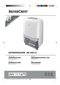
- DEHUMIDIFIER / LUFTENTFEUCHTER DÉSHUMIDIFICATEUR D'AIR SLE 200 B2
- DEHUMIDIFIER
- DÉSHUMIDIFICATEUR D'AIR
- ODVLHČOVAČ VZDUCHU
- LUFTAFFUGTER
- Warnings and symbols used .... 3
- Safety information 4
- Package contents and transport inspection 9
- Appliance description 10
- Using the appliance ....1 1
- Assembly 12
- Transport ....12
- Handling and use 13
- Cleaning 18
- Storage 19
- Troubleshooting 20
- Disposal 21
- Appendix 22
- Introduction
- Limitation of liability
- Proper use
- Warnings and symbols used
- Safety information
- ⚠️ DANGER! Risk of fatal injury from electrocution!
- Contact with live cables or components can result in a fatal injury!
- Danger of explosion! Risk of fire!
- Risk of disease!
- ! ATTENTION! Property damage!
- Basic safety instructions
- Package contents and transport inspection
- i Note
- Appliance description
- (See fold-out page for illustrations)
- Using the appliance
- Before initial use
- Electrical connection
- ! ATTENTION!
- Guidelines for operation
- Automatic defrosting
- Protection against overheating
- Assembly
- WARNING!
- Transport
- ATTENTION!
- Handling and use
- Switching the appliance on/off
- Operating status displays
- Selecting programmes
- DEHUMIDIFICATION
- DRY LAUNDRY
- Timer function
- Emptying the water tank
- Hose drainage
- Cleaning
- Cleaning the appliance
- Cleaning the filter
- Storage
- Troubleshooting
- Disposal
- Applies only to France:
- Disposal of the appliance
- The disposal is free of charge for the user. Protect the environment and dispose of this appliance properly.
- Disposal of the refrigerant
- Disposal of the packaging
- Appendix
- Technical data
- Notes on the EU Declaration of Conformity
- Warranty conditions
- Warranty period and statutory claims for defects
- Scope of the warranty
- Warranty claim procedure
- Service
- Importer
- Inhaltsverzeichnis
- Einführung 26
- ! ACHTUNG!
- Abb. 6
- Table des matières
- Introduction 52
- ① ATTENTION!
- Inhoud
- Inleiding 80
- Drainage met slang
- LETOP!
- Obsah
- Úvod....104
- Obr. 2
- Obr. 3
- ! POZOR!
- Obr. 6
- Spis treści
- W step 128
- ! UWAGA!
- Úvod....152
- Preprava
- Índice
- Introducción....176
- ! ¡ATENCIÓN!
- Indholdsfortegnelse
- Introduktion 200
- Dræning med slange
- ! OBS!
- Indice
- Introduzione 224
- ! ATTENZIONE!
- Tartalomjegyzék
- Bevezető 248
- ! FIGYELEM!
- Odvajanje vode s cevjo
- Slika 6
- Shranjevanje
- Pooblaščeni serviser
- SI ServisSlovenija
- Garancijski list
- Skladištenje
- Cuprins
- Introducere 320
- Scurgerea cu furtun
- ! ATENTIE!
- Съдържание
- Въведение....344
- ! ВНИМАНИЕ!
- ! ΕΙΔΟΠΟΙΗΣΗ!
- KOMPERNASS HANDELS GMBH
Brand : SILVERCREST
Model : SLE 200 B2
Category : Dehumidifier