KG 50 - Sander PROXXON - Free user manual and instructions
Find the device manual for free KG 50 PROXXON in PDF.
| Brand | PROXXON |
| Model | KG 50 |
| Product type | Cut-off saw |
| Rated voltage | 220-240 V, 50/60 Hz |
| Power consumption | 85 W (10 min) |
| Rotational speed | 8,000 rpm |
| Cutting speed | approx. 25 m/s |
| Base dimensions (L x W x H) | 100/135 x 132 x 100 mm |
| Total width | approx. 140 mm |
| Weight | approx. 1.5 kg |
| Clamp opening | 20 mm maximum |
| Stop adjustment range | up to 140 mm |
| Cutting angle | Adjustable with swivel table |
| Noise level | < 70 dB(A) |
| Protection class | II |
| Compatible materials | Metal, wood, plastic |
| Delivery contents | 5 cut-off discs, clamping key, clamp |
| Maintenance | Cleaning with soft cloth, tensioning timing belt |
| Safety | Wear safety goggles, use protective cover |
| Replacement parts | Cut-off disc ref. 28 152 |
Frequently Asked Questions - KG 50 PROXXON
User questions about KG 50 PROXXON
0 question about this device. Answer the ones you know or ask your own.
Ask a new question about this device
Download the instructions for your Sander in PDF format for free! Find your manual KG 50 - PROXXON and take your electronic device back in hand. On this page are published all the documents necessary for the use of your device. KG 50 by PROXXON.
USER MANUAL KG 50 PROXXON
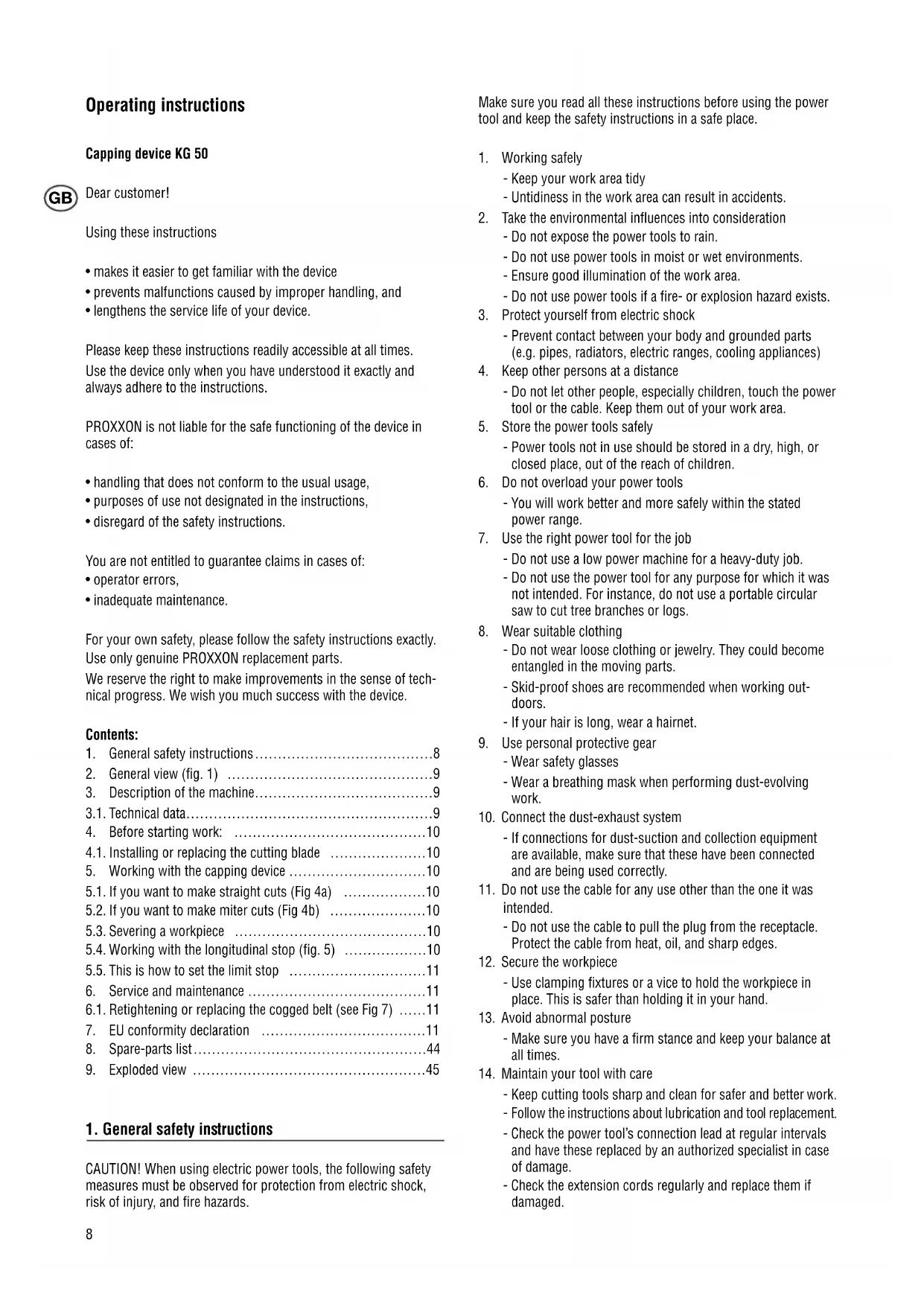
Operating instructions
Capping device KG 50

Dear customer!
Using these instructions
- makes it easier to get familiar with the device
- prevents malfunctions caused by improper handling, and
- lengthens the service life of your device.
Please keep these instructions readily accessible at all times. Use the device only when you have understood it exactly and always adhere to the instructions.
PROXXON is not liable for the safe functioning of the device in cases of:
- handling that does not conform to the usual usage,
- purposes of use not designated in the instructions,
- disregard of the safety instructions.
You are not entitled to guarantee claims in cases of:
- operator errors,
- inadequate maintenance.
For your own safety, please follow the safety instructions exactly. Use only genuine PROXXON replacement parts.
We reserve the right to make improvements in the sense of technical progress. We wish you much success with the device.
Contents:
- General safety instructions 8
- General view (fig. 1) 9
3.Description of the machine. 9
3.1. Technical data 9
4.Before starting work: 10
4.1. Installing or replacing the cutting blade 10 - Working with the capping device 10
5.1. If you want to make straight cuts (Fig 4a)
5.2.If you want to make miter cuts (Fig 4b) 10
5.3. Severing a workpiece 10
5.4. Working with the longitudinal stop (fig. 5) 10
5.5. This is how to set the limit stop 11 - Service and maintenance 11
6.1. Retightening or replacing the caged belt (see Fig 7) ....11 - EU conformity declaration 11
- Spare-parts list 44
9.Exploded view 45
1. General safety instructions
CAUTION! When using electric power tools, the following safety measures must be observed for protection from electric shock, risk of injury, and fire hazards.
Make sure you read all these instructions before using the power tool and keep the safety instructions in a safe place.
-
Working safely
-
Keep your work area tidy
-
Untidiness in the work area can result in accidents.
-
Take the environmental influences into consideration
-
Do not expose the power tools to rain.
- Do not use power tools in moist or wet environments.
- Ensure good illumination of the work area.
-
Do not use power tools if a fire- or explosion hazard exists.
-
Protect yourself from electric shock
-
Prevent contact between your body and grounded parts (e.g. pipes, radiators, electric ranges, cooling appliances)
- Keep other persons at a distance
-
Do not let other people, especially children, touch the power tool or the cable. Keep them out of your work area.
-
Store the power tools safely
-
Power tools not in use should be stored in a dry, high, or closed place, out of the reach of children.
-
Do not overload your power tools
-
You will work better and more safely within the stated power range.
-
Use the right power tool for the job
-
Do not use a low power machine for a heavy-duty job.
-
Do not use the power tool for any purpose for which it was not intended. For instance, do not use a portable circular saw to cut tree branches or logs.
-
Wear suitable clothing
-
Do not wear loose clothing or jewelry. They could become entangled in the moving parts.
- Skid-proof shoes are recommended when working outdoors.
-
If your hair is long, wear a hairnet.
-
Use personal protective gear
-
Wear safety glasses
-
Wear a breathing mask when performing dust-evolving work.
-
Connect the dust-exhaust system
-
If connections for dust-suction and collection equipment are available, make sure that these have been connected and are being used correctly.
-
Do not use the cable for any use other than the one it was intended.
-
Do not use the cable to pull the plug from the receptacle. Protect the cable from heat, oil, and sharp edges.
-
Secure the workpiece
-
Use clamping fixtures or a vice to hold the workpiece in place. This is safer than holding it in your hand.
-
Avoid abnormal posture
-
Make sure you have a firm stance and keep your balance at all times.
-
Maintain your tool with care
-
Keep cutting tools sharp and clean for safer and better work.
- Follow the instructions about lubrication and tool replacement.
- Check the power tool's connection lead at regular intervals and have these replaced by an authorized specialist in case of damage.
-
Check the extension cords regularly and replace them if damaged.
-
Keep handles dry, clean, and free of oil and grease.
-
Pull the plug from the electric socket
-
when the power tool is not being used, before maintenance, and when replacing tool parts such as the saw blade, drill, or milling cutter.
-
Never leave any tools keys or chucks plugged in
-
Before switching on, check to see if the key, chuck, and adjusting tools have been removed.
-
Prevent unintended starts
-
Ensure the switch is switched to the off position when plugging the plug into the electrical outlet.
-
Use an extension cable for outdoor areas
-
Use only approved and accordingly marked extension cables when working outdoors.
-
Be alert
-
Pay attention to what you are doing. Tackle the work with a reasonable attitude. Do not use the power tool if you lack concentration.
-
Check the power tool for any possible damage
-
Before continued use of the power tool, protective equipment and slightly damaged parts must be carefully checked for their flawless functioning and that they function as intended.
-
Check to see if movable parts are working perfectly and do not jam and if there are any damaged parts. All parts must be correctly installed and all conditions fulfilled to ensure the flawless operation of the power tool.
-
Damaged protective equipment and parts must be repaired or replaced by an authorized specialist workshop as directed unless otherwise specified in the operating instructions
-
Damaged switches must be replaced by a customer servicecenter.
-
Do not use any power tools in which the switch cannot be switched on and off.
-
CAUTION!
-
The use of other tools and accessories can result in the risk of injury.
-
Have your power tool repaired by a trained and skilled electrician
-
This power tools complies with the relevant safety regulations. Repairs may only be carried out by skilled and trained electricians with use of genuine spare parts. Otherwise, accidents could result for the user.
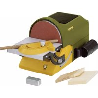
2. General view (fig. 1)
- Cutting head
- Cutting disk cover
- Blocking lever
- Cutting disk
- Device foot
- Setscrew
- Rotary plate
- Stop screw
- Spindle for clamping device
- Limit stop
- Clamping device
- Scale
- Fixing bore
3. Description of the machine
Thank you very much for acquiring a PROXXON KG 50 capping device:
It is perfectly suited for small but precise applications when cutting metal bars of up to diameters of ca. 10mm for cutting wood, and plastic bars or profiles.
The device consists of a cutting head and a device foot made from die-cast aluminum. The cutting head houses the device's electrical components as well as the synchronous belt-drive for actuating the cutting blade. It can be swiveled up and down through the use of a joint on the device foot and is held by a spring in the upper setting in the neutral position.
The device foot contains a circular table that can be rotated 45^ : This allows simple and precise fabrication even of diagonal cuts. On top of that, the scale on the side permits an exact and comfortable angular adjustment: after that, the circular table can be Loked in place using a thumbscrew. You can clamp the workpiece into the desired position using the vice. The vice has a span of max. 20mm and can hold size HO model-railroad tracks by using a prism on the top (see fig. 6). Fixating round materials is also made easy through the use of the groove worked into the jaw.
Even cutting workpieces to length is perfectly possible with this device through use of the limit stop: this can be set to a maximum length of 140mm
5-each ceramic-bonded cutting disks and a hollow hexagon wrench are included with the device.
3.1. Technical data
Dimensions and weights:
Device foot: ca. 100/135 x 132 mm
Height: ca. 100 mm
(when the cutting head is in the rest position)
Width: ca. 140 mm
Vice
jaw width: 30 mm
Span: 20 mm
Weight: ca. 1.4 kg
Motor:
Voltage: 220 - 240 Volt,
50/60 Hz
Power consumption: 85 Watt 10 min
Speed: 8000/min
Cutting speed: ca. 25m / sec
Noise emission: < 70 dB(A)
For use in dry environments only

Protection class II device

Please do not dispose in domestic waste!

4. Before starting work:
For safety reasons, the Proxxon KG 50 capping device comes delivered with a cardboard disk instead of a cutting disk. That means you need to install the cutting disk yourself, which is easily done. 5-each cutting disks are supplied in the scope of delivery of the device. Furthermore, after having used the device for a long time, replacing the cutting disk may become necessary if the old one is too worn. The procedure for replacement is the same and is described as follows:
4.1. Installing or replacing the cutting blade
Please note: You can acquire replacement-cutting blades for the machine in businesses under the no. 28 152!
Caution:
You must pull the mains plug before installation!
- Unscrew fastening screw 1 (see fig. 2) from the yellow protective cover 2 and pull up the cover.
- Lock shaft-1 (fig. 3) in place by pressing stopper 2. To do that, you need to turn the shaft a bit to find the corresponding notching position
- Remove fastening screw 3 and remove washer 4. Watch out for flat washer 5.
- Put on the new cutting disk
Caution!
The ceramic-bonded cutting disk is very sensitive to being bent.
Do not take hold of the disk to remove or pull the fastening screw.
The disk is very fragile.
Make sure that cutting disk 4 is correctly seated!
5. Reassemble by simply using the reverse sequence.
5. Working with the capping device
Note:
Safe and precise work is only possible if the device has been correctly fastened to a tabletop. This can be done with the enclosed C-clamp (shown in fig. 1), or with the help of screws. Bores (13, fig. 1) are available in the footplate.
Caution:
Make sure you always pull the plug before fixating or transporting the device!
Danger!
Never operate the capping device without the yellow protective cover and safety glasses!
The red safety lever (Fig. 1, pos. 3) must always be folded completely back into the resting position as otherwise, it could slip off if the cutting head is pushed by mistake and thus loses its blocking action.
You can start work after the device is standing on a stable support and the cutting disk has been installed. There are no other prepa
rations necessary and the workpiece to be cut can be clamped into the vice and separated (fig. 4 a/b). This is how it's done:
5.1. If you want to make straight cuts (Fig 4a)
- Make sure circular table 1 is in the 0^ position: The lug on black rotary table 2 must point to the 0^ mark on the scale in device foot 3. If not, please adjust it. If it is necessary to do so, remove thumbscrew 4 and push the rotary table into the corresponding position. Caution: the rotary table snaps-in at 0^ . After that, make sure you retighten the thumbscrew.
- Place workpiece 6 into vice 5, then align and tighten it. While doing so, mind the desired length of the „free“ end!
- If in doubt, after unlocking blocking lever 7 you can swivel cutting head 9 out of the switched-off (!) device so far that cutting blade 8 is seated on the workpiece. With this method, you can better estimate the later length of the workpiece.
5.2. If you want to make miter cuts (Fig 4b)
- Loosen thumbscrew 4 and set rotary table 1 to the desired angle. Use scale to help do this. Then retighten the stop screw.
- Place workpiece 6 into vice 5, then align and tighten it. While doing so, mind the desired length of the „free“ end!
- To do that, after unlocking blocking lever 7 you can swivel cutting head 9 from the switched-off (!) device so far that the cutting blade is seated on the workpiece here also. With this method, you can better estimate the later length of the workpiece.
5.3. Severing a workpiece
Switch the device on using on-off switch 10 and guide it down using slight pressure on recessed grip 11 until the cutting disk touches the workpiece. Caution:
While doing so, please actuate the red blocking lever: otherwise, the cutting head cannot be swiveled!
Increase the pressure on the workpiece only so much that the motor speed does not greatly decrease. That is how to sever a workpiece.
Caution!
It is not the contact pressure but the speed that generates high cutting power! Never use force! This unnecessarily stresses the device's mechanics and leads to poor results and increased wear!
Caution!
Never actuate the stopper while the device is running.
5.4. Working with the longitudinal stop (fig. 5)
The KG 50 capping device is supplied with an adjustable longitudinal stop (1). This means any desired number of workpieces can be cut to the same length. To do so, insert the workpiece to be cut into the vice pushed up to the limit stop and then clamp it in place. After severing the workpiece and loosening the vice, push
the material back to the limit stop, clamp it with the vice, and then cut it. This can be repeated as often as desired.
5.5. This is how to set the limit stop
- Loosen setscrew 2 using a hollow hexagon wrench (included in the scope of delivery). After that, the limit stop can be pushed into guide 3 up to the desired length. Make sure short-rod 4 is correctly oriented and that the workpiece meets the stop correctly!
- Using the setscrew, tightly clamp the limit stop.
6. Service and maintenance
Caution:
Pull the mains plug before making any adjustments, performing maintenance work, or carrying out repairs!
Note:
The capping device is basically maintenance free. However, to ensure a long service life you should clean the device after each use with a soft cloth, swab, or brush. A vacuum cleaner is also advisable for this.
External cleaning of the housing can be carried out using a soft, possibly moist cloth. While doing so, a mild detergent or other suitable cleansing agent can be used. Do not use solvents or cleansing agents containing alcohol (e.g. benzene, cleaning alcohol, etc.) as these can corrode the plastic housings.
Please do not dispose of the device in domestic waste! The device contains valuable substances that can be recycled. If you have any questions about this, please contact your local waste management enterprise or other corresponding municipal facilities.
After longer use, it could become necessary to retighten the caged belt. To do so, please follow these instructions:
6.1. Retightening or replacing the caged belt (see Fig 6)
Caution:
Pull the mains plug! Danger!
- Unscrew fastening screw 1 and remove side cover 2.
- Slightly loosen motor fastening-screw 3 and push pulley 4 to the rear until the necessary tension has been reached.
Caution!
The clogged belt must never be too tight! The clogged belt must be able to be pushed-in 6 - 8mm when lightly pressed with your finger!
3. Retighten the fastening screws and install the cover.
7. EU conformity declaration
Device name: KG 50
Part no.: 27150
We hereby declare the named product fulfills the regulations in the following EU directives:
EU low voltage directive 73/23/EEC
93/68/EEC
Applicable standards: DIN EN 61029/12.2003
EU EMC-directive 89/336/EEC
Applicable standards: DIN EN 55014-1 / 09.2002
DIN EN 55014-2/08.2002
EU machine directive 98/37/EEC
Applicable standards: DIN EN 61029/12.2003
Date: 12.11.04
Jörg Wagner

PROXXON S.A.
Device safety division
Mode d'emploi
Tronconenne KG 50
Cher client!
Ce mode d'emploi

Base appearechio: ca. 100/135 x 132 mm
Altezza: ca. 100 mm
5.3. Cortar Completely la pieza
Stojemission: < 70 dB(A)
Makun benytes i torre rum

Maskine i isolationsklasse II
Må不同程度

5.3. Skaering at emnet
Taend nu for maskinen pa afbryderen 10 og for det med et let tryk pa grebsfordybningen 11 nedad, indtil skareskiven berorer emnet. OBS: