ISC 240 Li - Saw FESTOOL - Free user manual and instructions
Find the device manual for free ISC 240 Li FESTOOL in PDF.
| Brand | Festool |
| Model | ISC 240 Li |
| Product type | Cordless saw for insulating materials |
| Motor voltage | 14.4 - 18 V |
| Stroke rate | 3000 rpm |
| Stroke | 26 mm |
| Max. cutting depth (short cutting blade) | 240 mm |
| Max. cutting depth (long cutting blade) | 350 mm |
| Weight without battery | 1.8 kg |
| Weight according to EPTA 01:2014 | 2.5 kg |
| Power supply | Festool BP 18 Li battery (14.4-18 V) |
| Compatible materials | Soft mineral wool (<100 kg/m³), rigid mineral wool (100-170 kg/m³), soft natural fibers (<90 kg/m³), PUR/PIR (<36 kg/m³), polystyrene (<45 kg/m³) |
| Available cutting blades | Serrated saw blade (SG-240/W-ISC, SG-350/W-ISC) and cross-tooth saw blade (SG-240/G-ISC, SG-350/G-ISC) as optional |
| Mandatory protective equipment | Hearing protection, safety goggles, protective gloves, P2 dust mask |
| Sound pressure level | L_PA = 86 dB(A) |
| Sound power level | L_WA = 97 dB(A) |
| Vibrations (main handle, mineral wool) | a_h = 2.5 m/s² (K=2 m/s²) |
| Vibrations (additional handle, PUR 240 mm) | a_h = 7.5 m/s² (K=2 m/s²) |
| Features | Two-sided on/off switch with double impulse, warning beep, dust extraction connection (Ø 27 mm), lint filter |
| Maintenance and cleaning | Clean the lint filter and the chip evacuation opening of the dust extraction connection regularly |
| Spare parts and repairability | Use only original Festool parts; repair by the manufacturer or authorized workshops |
| General information | Cordless saw designed for cutting insulating materials only; do not use on wood, metal, or particle boards |
Frequently Asked Questions - ISC 240 Li FESTOOL
User questions about ISC 240 Li FESTOOL
0 question about this device. Answer the ones you know or ask your own.
Ask a new question about this device
Download the instructions for your Saw in PDF format for free! Find your manual ISC 240 Li - FESTOOL and take your electronic device back in hand. On this page are published all the documents necessary for the use of your device. ISC 240 Li by FESTOOL.
USER MANUAL ISC 240 Li FESTOOL
Cordless insulating- Serial number 1 material saw No de série 1
Head of Product Development
Ralf Brandt
Head of Product Conformity
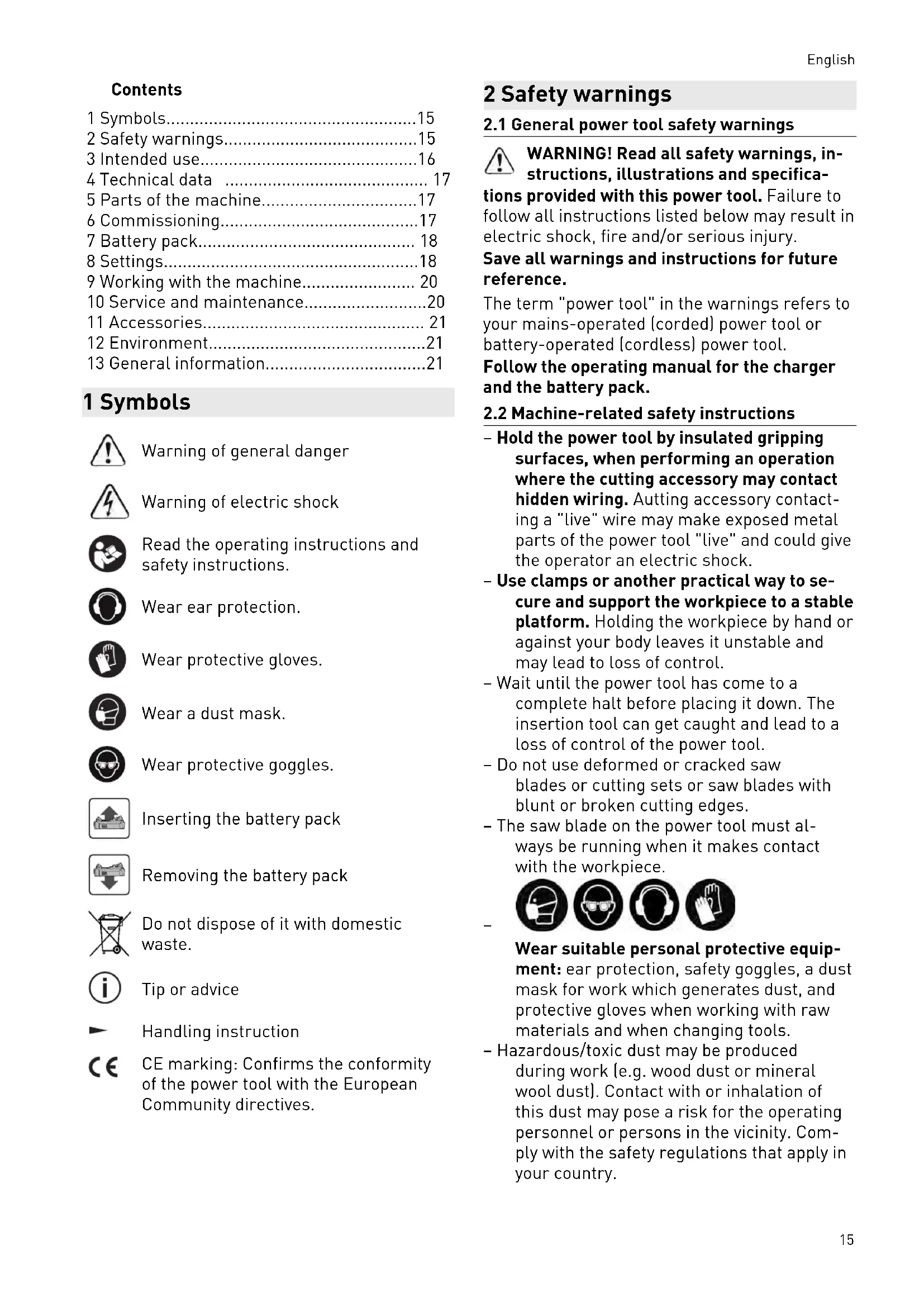
1 Symbols. 15
2 Safety warnings. 15
3 Intended use. 16
4 Technical data 17
5 Parts of the machine. 17
6 Commissioning. 17
7 Battery pack. 18
8 Settings. 18
9 Working with the machine. 20
10 Service and maintenance. 20
11 Accessories 21
12 Environment. 21
13 General information. 21
1 Symbols

Warning of general danger

Warning of electric shock

Read the operating instructions and safety instructions.

Wear ear protection.

Wear protective gloves.

Wear a dust mask.

Wear protective goggles.

Inserting the battery pack

Removing the battery pack

Do not dispose of it with domestic waste.

Tip or advice

Handling instruction

CE marking: Confirms the conformity of the power tool with the European Community directives.
2 Safety warnings
2.1 General power tool safety warnings

WARNING! Read all safety warnings, instructions, illustrations and specifica
tions provided with this power tool. Failure to follow all instructions listed below may result in electric shock, fire and/or serious injury.
Save all warnings and instructions for future reference.
The term "power tool" in the warnings refers to your mains-operated (corded) power tool or battery-operated (cordless) power tool.
Follow the operating manual for the charger and the battery pack.
2.2 Machine-related safety instructions
- Hold the power tool by insulated gripping surfaces, when performing an operation where the cutting accessory may contact hidden wiring. Autting accessory contacting a "live" wire may make exposed metal parts of the power tool "live" and could give the operator an electric shock.
- Use clamps or another practical way to secure and support the workpiece to a stable platform. Holding the workpiece by hand or against your body leaves it unstable and may lead to loss of control.
- Wait until the power tool has come to a complete halt before placing it down. The insertion tool can get caught and lead to a loss of control of the power tool.
- Do not use deformed or cracked saw blades or cutting sets or saw blades with blunt or broken cutting edges.
- The saw blade on the power tool must always be running when it makes contact with the workpiece.


Wear suitable personal protective equipment: ear protection, safety goggles, a dust mask for work which generates dust, and protective gloves when working with raw materials and when changing tools.
- Hazardous/toxic dust may be produced during work (e.g. wood dust or mineral wool dust). Contact with or inhalation of this dust may pose a risk for the operating personnel or persons in the vicinity. Comply with the safety regulations that apply in your country.

Wear a P2 respiratory mask to protect your health.
- Always connect the machine to a dust extractor when performing work that generates dust.
- Do not use power supply units or third-party battery packs to operate cordless power tools. Do not use third-party chargers to charge the battery packs. The use of accessories not expressly authorised by the manufacturer can result in electric shocks and/or serious accidents.
2.3 Emission levels
The levels determined in accordance with EN 62841 are typically:
Sound pressure level L PA = 86dB(A)
Sound power level L WA = 97 dB(A)
Uncertainty K = 5 dB


CAUTION
Noise generated when working
Risk of damage to hearing
Use ear protection.
Vibration emission level a_h (vector sum for three directions) and uncertainty K measured in accordance with EN 62841:
| Flexible mineral wool | ||
| 240 mm 350 mm | ||
| Main handle | ah=2.5 m/s2 | ah=2.5 m/s2 |
| Auxiliary handle | ah=4 m/s2 | ah=4.5 m/s2 |
| Uncertainty | K=2 m/s2 | K=2 m/s2 |
| PUR | ||
| 240 mm 350 mm | ||
| Main handle | ah=4.5 m/s2 | ah=8.5 m/s2 |
| Auxiliary handle | ah=7.5 m/s2 | ah=14 m/s2 |
| Uncertainty | K=2 m/s2 | K=5 m/s2 |
The specified emission levels (vibration, noise)
- are used to compare machines.
-
They are also used for making preliminary estimates regarding vibration and noise load during operation.
-
They represent the primary applications of the power tool.

CAUTION
The emission values may deviate from the specified values. This is dependent on how the tool is used and the type of workpiece being machined.
The actual load during the entire operating cycle must be evaluated.
Depending on the actual load, suitable protective measures must be defined in order to protect the operator.
3 Intended use
The cordless insulating-material saw is designed to saw flexible insulating materials made of mineral wool (glass or stone wool) or natural fibres (e.g. wood or hemp fibres) as well as to saw insulating materials made of PUR/PIR (polyurethane hard foam), polystyrene or pressure-resistant mineral wool.
In accordance with the intended use, only insulating materials with the following raw densities may be machined:
Flexible natural fibres < 90kg / m^3
Flexible mineral wool < 100kg / m^3
Pressure-resistant mineral 100-170 kg/m³ wool
$$ \mathrm {P U R} / \mathrm {P I R} < 3 6 \mathrm {k g} / \mathrm {m} ^ {3} $$
$$ \text {P o l y s t y r e n e} < 4 5 \mathrm {k g} / \mathrm {m} ^ {3} $$
The cordless insulating-material saw is not suitable for sawing chipboard, metal, wood or pressure-resistant insulating materials made of natural fibres.
This power tool may only be used by experts or instructed persons.
Only saw insulating materials with the cutting set intended for this purpose, see section 6.2.
The user is liable for damage and accidents caused by improper and non-intended use.
- intended for use with BP Festool battery packs of the same voltage class.
4 Technical data
| ISC 240 Li cordless insulating-material saw | |
| Motor voltage 14.4-18 V | |
| Stroke rate | 3000 rpm |
| Stroke length 26 mm | |
| Max. cutting depth | |
| Cutting set, short 240 mm | |
| Cutting set, long 350 mm | |
| Weight without battery pack 1.8 kg | |
| Weight as per EPTA procedure | 2.5 kg |
| 01:2014: | |
5 Parts of the machine
[1-1] Auxiliary handle
[1-2] Main handle
[1-3] Lint filter
[1-4] Buttons for releasing the battery pack
[1-5] On/off switch
[1-6] Rotary knob for changing the cutting set
[1-7] Cutting set
[1-8] Protective cover
[1-9] Extractor connector
Accessories shown or described are not always included in the scope of delivery.
The illustrations specified are located at the beginning and end of the operating instructions.
6 Commissioning
6.1 Switching on/off
The power tool features an on/off switch on both sides. Use either switch to switch the power tool on or off.
Switching on
Press the on/off switch [1-5] twice in quick succession.
Switching off
Press the on/off switch [1-5] once.
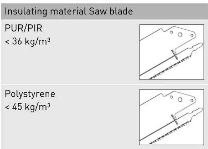
6.2 Selecting a cutting set

Only use cutting sets that have been approved by the manufacturer.
Two cutting sets, each available in two lengths, are available for machining.
Cutting set with serrated saw blade (available as an accessory depending on the model)
The cutting set with serrated saw blade (SG-240/W-ISC, SG-350/W-ISC) consists of a guide rail with both a movable and a fixed saw blade.
The cutting set with serrated saw blade must be adjusted before initial operation, see section 8.3.
To ensure an optimum tool life for the serrated saw blade, use a separate cutting set for mineral wool and a separate cutting set for natural fibres. The saw blade is no longer suitable for sawing natural fibres once it has been used to saw mineral wool.
Cutting set with cross-set saw blade (accessory)
The cutting set with cross-set saw blade (SG-240/G-ISC, SG-350/G-ISC) consists of a guide rail and a movable saw blade.
Insulating material Saw blade
Flexible natural fibres < 90kg / m^3
Flexible mineral wool < 100kg / m^3
Pressure-resistant mineral wool 100 - 170kg / m^3
7 Battery pack
- Inserting the battery pack [2a]
- Removing the battery pack [2b]
7.1 Capacity display
The capacity display [2-1] indicates the charge of the battery pack for approx. 2 seconds after the button [2-2] is pressed:
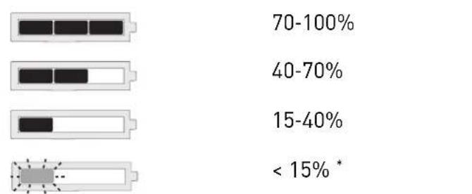
- Recommendation: Charge the battery pack before any further use.
Further information about the charger and battery pack with capacity indicator can be found in the corresponding operating manual.
8 Settings

Risk of injury from hot and sharp insertion tool
- Do not use any blunt or faulty insertion tools.
- Wear protective gloves when handling an insertion tool.
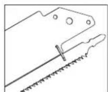
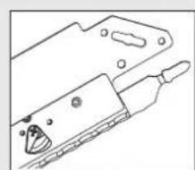
If necessary, push the extractor connector [3-1] upwards.
- Please the rotary knob.
Open the cover flap.
- Torn the lever on the clamping sleeve [3-2] anti-clockwise to unlock the clamping sleeve.
- Filled the movable saw blade on the single-cam shaft (T shaft) [3-4] along the guide rail [3-3] as far as it will go to remove it.
Fsh the movable saw blade into the clamping sleeve as far as it will go.
- T6n the cutting set clockwise by approximately 30^ until the guide rail is level. The retaining pins [3-5] in the guide rail holder are seated fully in the recesses in the guide rail.
When tightening the rotary knob, always keep the cover flap pressed down. Otherwise, the thread could become damaged.
0se the cover flap.
- Keep the cover flap pressed down and tighten the rotary knob.
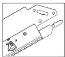
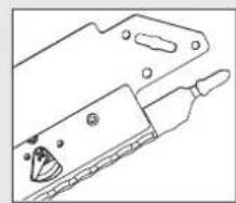
8.2 Removing the cutting set [4]
If necessary, push the extractor connector [3-1] upwards.
- Please the rotary knob.
Open the cover flap.
- Torn the lever on the clamping sleeve [4-1] anti-clockwise.
The clamping sleeve is unlocked.
- Torn the cutting set anti-clockwise by approximately 30^ .
- Remove the saw blade from the clamping sleeve.
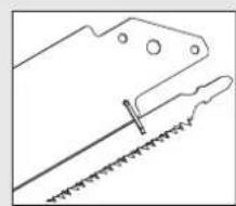
8.3 Adjusting the cutting set with serrated saw blade [5]
If the fixed saw blade can no longer be positioned underneath the movable saw blade, the adjusting levers [5-1] are worn. The cutting set must be replaced.
Adjust the cutting sets with serrated saw blade before initial operation. The movable saw blade must be positioned above the fixed saw blade.
- Move the protective cover until the lower adjusting lever [5-1] is free.
- Torn the adjusting lever until both saw blades are level and parallel with one another.
- Torn the adjusting lever clockwise by one latching point.
The movable saw blade is positioned above the fixed saw blade.
Push the protective cover back.
- Carry out the same steps for the upper adjusting lever.
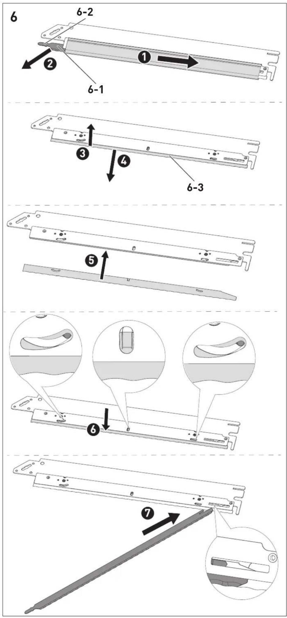
8.4 Changing the serrated saw blade [6]
- Disconnect the cutting set from the power tool.
- Remove the protective cover.
Pull the movable saw blade [6-1] on the single-cam shaft (T shaft) [6-2] away from the guide rail at angle in order to remove it from the guide rail. - Rise the fixed saw blade [6-3].
- Fill the fixed saw blade out of the guide rail.
- Fesh a new fixed saw blade into the guide rail.
- F6sh the fixed saw blade downwards until the recesses in the saw blade engage with the protrusions of the adjusting levers.
- Hold a new movable saw blade against the single-cam shaft (T shaft) and push the end forwards into the guide rail at an angle.
The saw blade is hooked into the end of the guide rail.
Fit the protective cover.
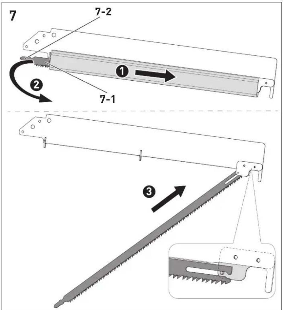
8.5 Changing a cross-set saw blade (accessory) [7]
-
Disconnect the cutting set from the power tool.
-
Move the protective cover.
- the movable saw blade [7-1] on the single-cam shaft (T shaft) [7-2] away from the guide rail at an angle in order to remove it from the guide rail.
- Hold a new movable saw blade against the single-cam shaft (T shaft) and push the end forwards into the guide rail at an angle.
The saw blade is hooked into the end of the guide rail.
Fit the protective cover.
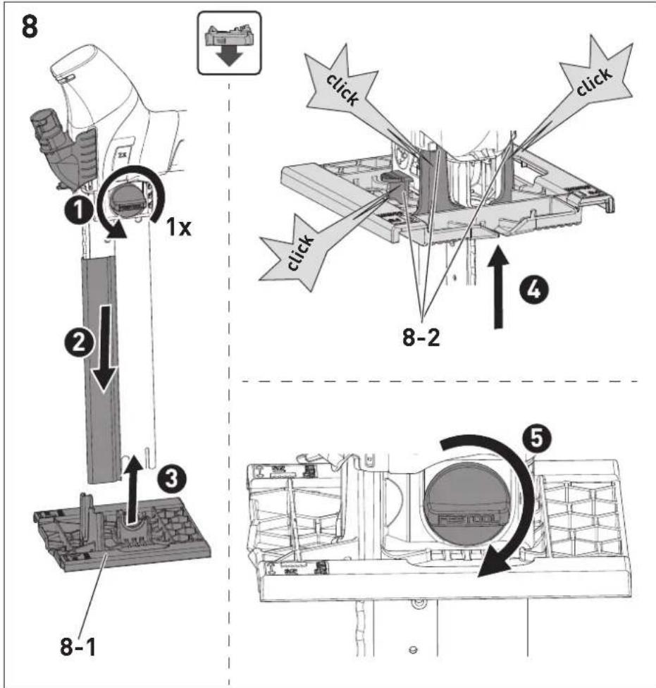
8.6 Fitting the base adapter [8]
If necessary, push the extractor connector [3-1] upwards.
-lease the rotary knob by one turn.
- S2de the protective cover downwards by approx. 4 cm.
Insert the base adapter [8-1] at the end of the cutting set.
- F6sh the base adapter towards the power tool until it latches into it at the three latching points [8-2].
se the rotary knob.
Make sure that the base adapter [8-1] latches into the power tool at the three latching points [8-2].
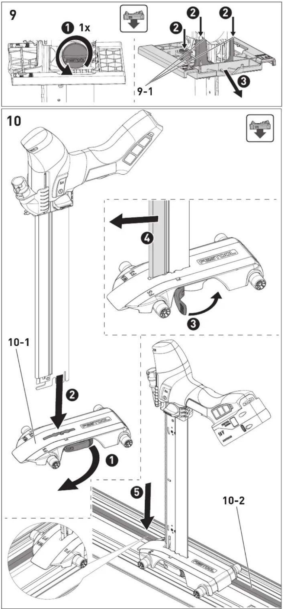
8.7 Removing the base adapter [9]
- Push the extractor connector [3-1] upwards if required.
-lease the rotary knob by one turn. - Release the base adapter at the three latching points [9-1].
- F3sh the base adapter downwards and away from the tool at an angle.
- Close the rotary knob.
8.8 Changing the guide rail slide [10]
Always use the guide rail slide [10-1] in conjunction with a guide rail and only together with the cutting set with serrated saw blade.
- Please the lever.
Iert the cutting set.
-Obse the lever. - Move the protective cover.
- Place the guide rail slide on the grooves [10-2] provided in the guide rail. Removal is performed in reverse order.
8.9 Extracting dust

WARNING
Heath hazard posed by dust
Always work with an extractor.
Comply with national regulations.
The extractor connector enables the power tool to be connected to a dust extractor (hose diameter: 27mm ).
Gently apply pressure to push the extractor connector downwards.
The chip ejection opening on the lower part of the extractor connector must be cleaned regularly with a brush.
Gently apply pressure to push the extractor connector downwards.
Clean the chip ejection opening with a brush.
9 Working with the machine

CAUTION
Materials which produce a lot of dust Damage to the machine due to the ingress of dust, risk of injury
Do not work overhead.
Always work with a lint filter.
When working, hold the power tool by the handle and guide it along the desired cutting line. For precise cuts and smooth running, use two hands to guide the power tool.
9.1 Freely guided sawing
The triangular pointer on the extractor connector indicates the cutting line of the saw blade. Freely guided sawing is also possible with the base adapter.
9.2 Sawing with the FS/2 guide rail (accessory)
Using the Festool FS/2 guide system makes it easier to produce straight and precise cuts.
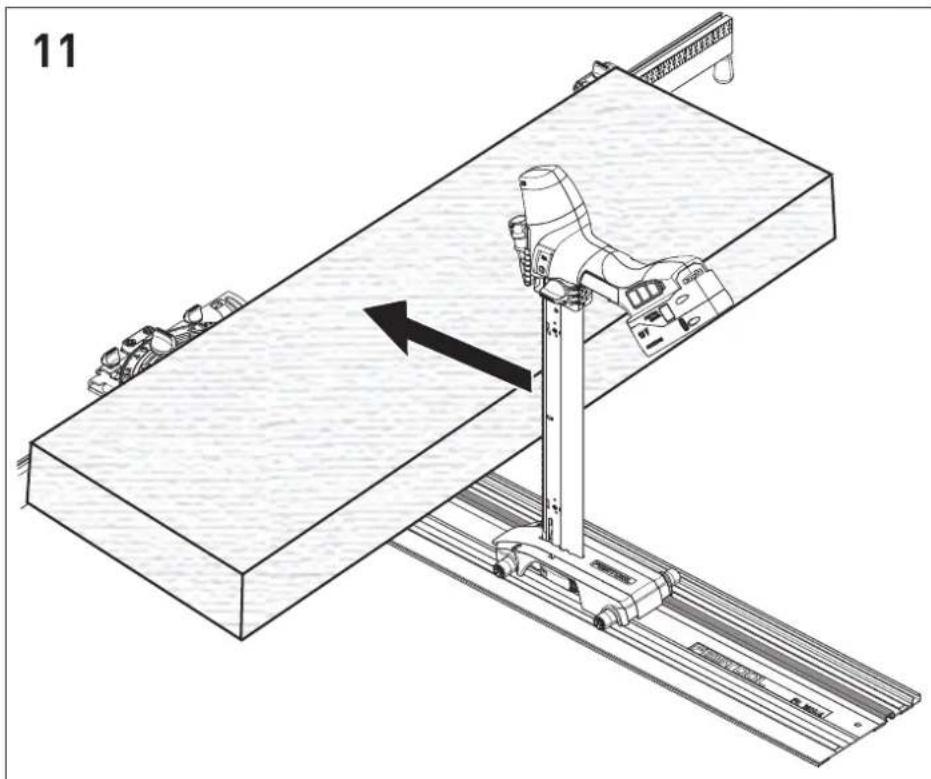
Flexible insulating material [11]
- Place the flexible insulating material on the guide rail.
Position the power tool, with the guide rail slide fitted, on the guide rail.
Align the insulating material with the WAsC 240 angle stop if required, see section 11.1.
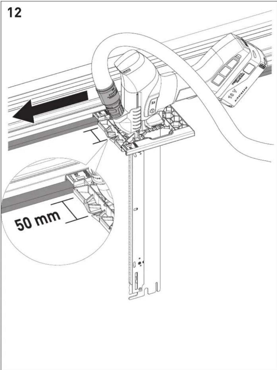
Pressure-resistant insulating material [12]
- Place the guide rail on the pressure-resistant insulating material.
Position the power tool, with the base adapter fitted, on the guide rail.
9.3 Acoustic warning signal
Acoustic warning signals sound and the machine switches off in the following operating states:

peep 一一
Battery flat or machine overloaded.
- Change the battery.
- Reduce the machine load.

peeppeep一
Machine or battery has overheated.
- When it has cooled down, start the machine again
- Check that the cooled-down battery is functioning properly with the charger.
10 Service and maintenance


WARNING
Risk of injury, electric shock
Always remove the battery pack from the power tool before performing any maintenance or service work.
- All maintenance and repair work which requires the motor housing to be opened should always be carried out by an authorised service workshop.

Customer service and repairs must only be carried out by the manufacturer or service workshops. Find the nearest address at: www.festool.co.uk/service
Always use original Festool spare parts. Order no. at: www.festool.co.uk/service
Damaged safety devices and components must be repaired or replaced in a recognised specialist workshop, unless otherwise indicated in the operating manual.
Follow the instructions below:
- Keep the vents on the power tool, charger and battery pack free and clean to ensure cooling.
- Keep the terminal contacts on the power tool, charger and battery pack clean.
- Regularly remove dust deposits from the extractor connector.

Follow the instructions enclosed with the battery pack for service, maintenance,
disposal and transport of the battery pack.
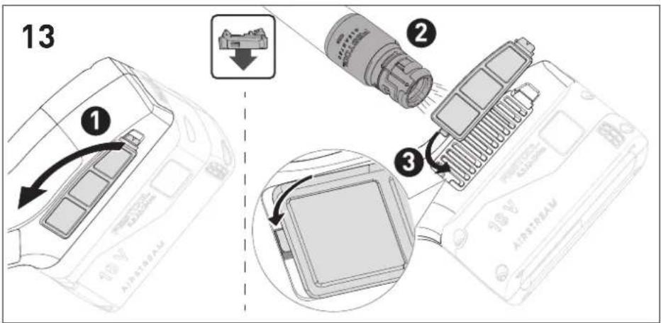
10.1 Cleaning the lint filter [13]
To prevent the power tool from overheating, the lint filter must be cleaned regularly on both sides.
- Remove the lint filter.
Extract dust from the lint filter.
Insert the lint filter.
11 Accessories
The order numbers of the accessories and tools can be found in the Festool catalogue or on the Internet at "www.festool.com".
11.1 WA-ISC 240 angle stop
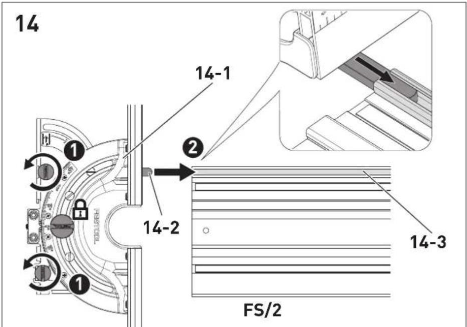
The WA-ISC 240 angle stop [14-1] is used to saw flexible insulating materials with the FS/2 guide rail.
Fitting the angle stop on the guide rail [14]
![FESTOOL ISC 240 Li - Fitting the angle stop on the guide rail [14] - 1](/content/2026/04/595269/images/09615d151c61310998f49042eb3ba4eac4ea93f168c0f537affd6d01fc1a0327.jpg)
The angle stop can only be fitted to the side of the guide rail where the guide spring [14-2] can engage in the guide
groove [14-3].
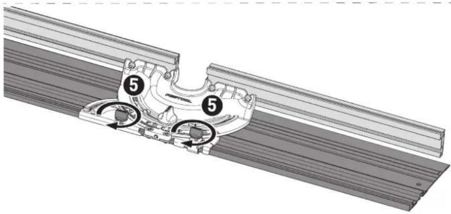
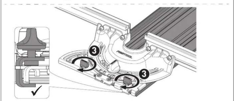
- Please the rotary knobs.
- Place the angle stop on the guide rail and push it forwards until it is fully fitted on the guide rail.
- Tighten the rotary knobs.
The angle stop is firmly seated in the guide.
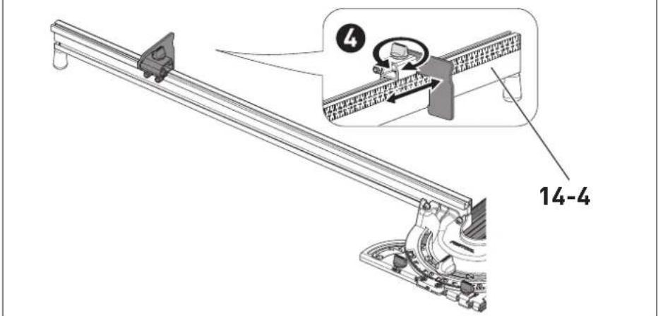
Adjust the stop ruler [14-4].
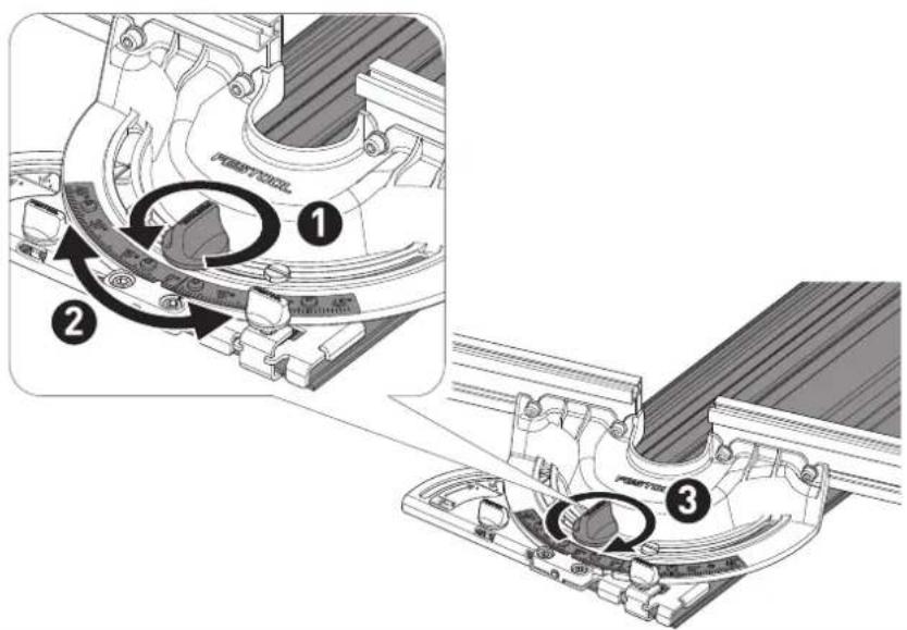
Setting the angle [15]
- Release the rotary knob.
- the desired angle by using the pointer.
- 13 hten the rotary knob.
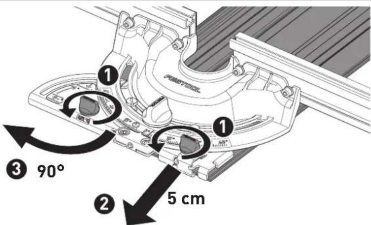
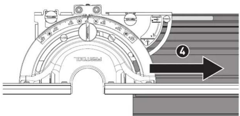
Move the angle stop into the transport position. [16]
- Please the rotary knobs.
- the angle stop out of the guide rail by 5 cm.
- 18n the angle stop clockwise by 90^ .
- Fosh the angle stop on the guide rail into the transport position.
- Tighten the rotary knobs.
To move the angle stop back into the working position, carry out the steps in reverse order.
12 Environment

Do not dispose of the device in the household waste! Recycle devices, accessories and packaging. Observe appli-national regulations.
EU only: In accordance with the European Directive on waste electrical and electronic equipment and implementation in national law, used power tools must be collected separately and handed in for environmentally friendly recycling.
Information on REACH: www.festool.com/reach
13 General information
Imported into the UK by
Festool UK Ltd
1 Anglo Saxon Way
Bury St Edmunds
IP30 9XH
Great Britain
13.1 Bluetooth®
The Bluetooth® word mark and the logos are registered trademarks of Bluetooth SIG, Inc.; they are used by TTS Tooltechnic Systems AG & Co. KG, and therefore by Festool, under licence.
Sommaire
Wartel is ontgrendeld.
Machine of accu is oververhit.
peeppeep一
Varning for allman risk

Varning for elstotar

| 70-100% |
| 40-70% |
| 15-40% |
| < 15% * |
YcTaHOBka aKKymyIaTopa

ÖtcoeüHHeHne aKKymyIaTopa

He BbIbpaBbIaIe BMeCTe C 6bITOBbIMN OTXOJaMn.

HctpyKzna,pekomeHaazn
HCTpyKznaNo nCnOJb30BaHNIO
C
MapKnpOBka CE:ПодТбержДаeТ coOTBETCTBnE 3JIeKTponHCTpyMeHTa OCHOBHBIM Tpe6OBAHNm DInpeKTINB EC.
2Уka3aHЯ NO TexHnKe 6e3oNaChOCTN
2.1 06ие yka3aHnno TeXnke 6e3oNaChOCTnДЯ 3JIeKTPoHnCtpyMeHTOB

Pa6oTaIeB3aUHTbIXHayuHnKax.
3haeHne Bn6paun a, no TpE M OcM (BeKtop-Ha cymma) n Ko3ΦnueHT nopreeHocTn K, onpeJeHHbIe no EN 62841:
6 PndroToBka K pa6ote
YcTaHOBka aKKMyJrTopa [2a]
BbHmHaHne aKKymyIaTopa [2b]
7.1 HnKaTOp EMcOCTN
HdNKaTOp EMKoCTn [2-1] NOKa3bIBAe TypOBeHb 3apyaakymJrToPa npHaKaTuN KHOJIKN [2-2]B TeueHne 2 cekyHd:

70—100%

40—70%

15—40%
< 15%*
- PekomeHdau: 3aprnte aKKymyIaTOp pepeedero daJIbHeuM NcNoJIb3OBAHneM.
I Ioppo6HnHΦOpMaunO 3apAnHom ycTPOINCTBe n aKKyMylrTope C HnKAtOpom EMKoCTn CoepXHTcB COOTBeTCTByIOx npKOBOIDTBAX NO 3KcnnyatauN.
8 Hac troponk

PPEyPPEKDEHNE
OnachOcTb TpaBMnpoBaHn
- IpepeIIO6bIMn pa6oTAMn Ha 3JIeKTpOuHCTpyMeHTe BbIHMaIte n3 HeRo aKKyMylaTOp.


BHIMAHNE
OnacHocTb TpaBMnpoBaHnCnIbHo HarpeBaIOUmMcN OCTpbIM pa6OuM INHCTpyMeHToM
He nCnoJb3yIe 3aTynnBwneecn HeNCnpaBhbIe pa6OuHnHCTpyMeHTbl.
- Pn pa6oTe c HcTpymeHToM noIb3yITeCb 3aunTHbIMN nepaTkAm.

PPEyPPEKDEHNE
OctpbIe NnBhIe NOJIOTha
Onachoctb TpaBMnpoBaHn
Pn BInOpHeHHBex pa6oT Ha 3JeK- TpOHHCTpyMeHTe 3aKpbBaItepeXyUIO raphNtpy 3aUnTHbIM KoxyXOM.
IOnBnXHoe NOnTOHo JExKHT HaI HeNoDnXhblM.
3aBnHbTe Ha3aD 3aUHTbI KOxYX.
- NOBTOPNE BCE DeIcTBnC BepxHm peryJInpOBOUHbIM pbIaROM.
8.4 3aMeHa NINbHOrO NOJIoTHa C BOJIHNCTbIM Je3BnEM [6]
- OToCoeHnHTe peKyuIyI rapHnTpy oTHCTpyMeHtA.
MMNTe 3aunTHbI KOxyX.
TAYHNTe NOBHXHOE NINbHOe NOIOT-HO [6-1], DEpXa ero 3a T-XBOcTOBnK [6-2], HAnCKOCOK n3 HAnpaBJIIOUe INaHNK.
3 PnpnoDnHmnte HeNodBnXHoe nOToHO [6-3].
TAYHNTe HeNoDBNXHoe NIOIOTHO 3Ha npablaIOUeNnAHN.
BraBBTe HOBoE NOJIOTHOB NlaHky.
6 PnKMMTe HeNoBHXHoe NoIOTHO BHN3 Do KCaUN BbEMOK Ha NoIOTHE BBICTy- nax Ha perynpoBOHybIX pbIarax.
B TaBbTe NOBHXHoe NINbHoe NOJOTHO, 1epka ero 3a T-XBOCTOBHK, KOHCOM BHa- npabJIIOUyIO PAnHKy.
HnIbHoe nOIoTHo hKcpyetcHa KOHe Ha npabJIOUe HnAHN.
YcTaHOBnTe Ha MeCTO 3aUNTHbI KOKyX.
8.5 3aMeHa NnIbHOro nOIoTHa c pa3BeDeyHHbIMN 3y6bMyn (ocHaCTka) [7]
- OToCoeHnHTepeKyuIyOrapHNTpyOTNHCTpyMeHtA.
MMNTe 3aunTHbI KOxyX.
Pycckn
TAYHNTe NOBHXHoe NnIbHOe NOIOT-HO [7-1],epka ero 3a T-xBOcTOBnK [7-2] HAnCKOCOK n3 HAnpaBJIIOUe INaHKn.
BcTaBbTe NOdBnKHoe NnIbHOe NoIOTHO, epka ero 3a T-xBOCTOBNK, KOHcOM BnpeEd HnPaBnIOUyIO nlaHKy.
HnIbHOe nOJIOTHo fKcnpyETcB KOHc HApabJIOUe nnAHN.
YcTaHOBnTe Ha MeCTO 3aUHTbI KOKyX.
8.6 YctaHOBka IJIITbI-aJAnTepa [8]
CdBnHbTe natpy6ok nbIeYdaJeHn [3-1] BBepx.
- Na6bTe BnHT-6apaWeK Ha oDHH o60-poT.
BnHbTe 3aunTHbI KOKx Bn3 npmepHO Ha 4 cm.
HcaNTe pHTy-aaTep [8-1] Ha KOHeupeKyuuei rapHHTypbl.
HaBnHbTe Pnty-aanTep Ha HnctpyMeHT Do eE fNkcaun B Tpex ToKax [8-2].
3aTAHnTe BnHT-6apaWeK.
I IpocneJeNTe 3a TeM,HTo6bI Pnnta-aanTep [8-1] 3aΦnKcnpoBaJacb B Tpex ToqKax [8-2] Ha NHCTpyMeHTe.
8.7 Chartye Пл'tы-адanTepa [9]
CdBnHbTe naTpy6ok nbIeYdaJeHn [3-1] BBepx.
na6bTe BnHT-6apaweK Ha oINH o6o-poT.
F2cKcpyTe pnty-aanTep B Tpex ToKax [9-1].
HxMHa HnIHTy-adaTep HaNcKocOK BHN3, CHIMTE e c nHCTpyMeHTa.
3aTaNHT BnHT-6apaWeK.
8.8 3aMeHa cala30K uHbI-HanpaBlaIOsei [10]
Ipnpa6oTe c uHOn-HanpaBraIOuSei npexyuuei rapHHTyPoC BOHNCTbIM Je3-BnEM Bcerda nCnoJIb3yIte caJa3KN [10-1].
BcBeuTe pblur.
BraBbTepeKyuIyIraPHTypy.
3KpoTe pbIur.
MMTe 3aUHTbI KOKyX.
YaHOBnTe cana3Kn B npedyCMoTpeH- HbIe IJIa HIX Na3bl [10-2] Ha 5uHe-HanpaB- JIAIOUeJ.
Jemontk BblnoHReTcB 06paTHoN nocJeOBaTeJIbHOCTN.
8.9ПыileydaJIeHne

PPEyPPEKDEHNE
OnachoctbIJIy 3IopOBbI npN KOHTaKTe c nbIJIbIO
Pa60TaTb 6e3 cncTeMbI nbJIeYdaJIeHnra 3a- npeuaaetca.
Co6JIIOJaIeHaunOHaIbHbIe npedncaHna.
Yepe3 natapy6ok nbileydaJIeHnI INhctpyMeHT coedHHaTc c nbileydaJIaHouI m aIInapaTOM (dnaMeTp 7HaHra 27 MM).
- IeKIM HaxaTneM cBnHbTe NaTpby6ok nbIJIeydaJIeHnBn3.
Hyxho nepnoonueckn npouuatab oTBepctne IaBb6pca onnloK B HnxHne qactn naTppyka IIydaJeHna.
- Ierkm HaxaTneM cBnHbTe naTp6ok nbI-JeYdaJeHnBHN3.
PpounCTne OTBepCTne IJRA BbIbpoca onnIOK uETKOJ.
9 Pa6ota c nHcTppyMeHTOM

BHIMAHNE
CnIbHonblIaJIuNe MaTePnaJIbI
AkkymyIaTOp pa3pJxKeH nNn HCTpyMeHT pa6oTaET c neperpy3-KoI.
- 3aMeHnte aKKyMnyTOp.
-ymeHbWnteHarpy3KuHaNHCTpyMeHT.

peeppeep一
MaunHka nIaakymyJTop nepeperpencb.
- PpOdoJIxNte pa6Oty nocne oxlaXdEHNmaUNHKn.
- PpOBepbTe pa6oTocnoc6-HocTb oxJaXdEHHoro aKKMyJyTopa C NOMOu 3apAHO- ro yCTpoiCTBa.
10 06cnyxnbHne n yxoD

PPEyPExKdEHNE
Onachoctb TpaBMnpoBaHHy, ydp TokOM
- Ipepe npoBeHnem JIO6bIX pa60T no 06-cIyXuBaHnIO BbIHMaTe aKKymJrTop n3 HcTppyMeHTa.
Bce pa6oTbI no peMOHTy nTexHnueckOMy 06cnyKuBaHHIO, KoToPbIE Tpe6byOT OTKpbI- BaHHa KOpNyca DnRgATEJI, DOJXHbI BblONHrTbcra ToIbKO CneUaJIncTaMn ABTOpN3O-BaHHoMaCTepCKoCepBuChOH cLyXbI.

CepBnchoe o6cnyKbHaHne n
peMOHT OJXHbI BblIOJIHrTbcra TOnb- KO CneuaJIncTaMn HpMbI-N3rTOBNTeJI NIN B cepBcHcOIMacTePcko. AApEc 6nKaiWe mAcTeP
Declaration of Conformity
We as the manufacturer Festool GmbH, Wertstraße 20, 73240 Wendlingen, Germany declare under our sole responsibility that the product(s):
Designation:
Designation of Type(s):
Serial number(s) 11
Cordless insulating-material saw
ISC 240 Li
10021362
fulfills all the relevant provisions of the following UK Regulations:
S.I. 2008/1597
S.I. 2016/10912
S.I. 2017/12063
S.I. 2012/3032
Supply of Machinery (Safety) Regulations 2008
Electromagnetic Compatibility Regulations 2016
Radio Equipment Regulations 2017
Restriction of the Use of Certain Hazardous Substances in Electrical and Electronic Equipment Regulations 2012
and are manufactured in accordance with the following designated standards:
BS EN 62841-1:2015
BS EN 62841-2-11:2016+A1:2020
BSEN55014-1:20172
BSEN55014-2:2015 21
EN 300 328:2016 V2.1.1
EN301489-1:2017V2.1.1
EN301489-17:2017V3.1.1a)
BS EN IEC 63000:2018
in the specified serial number range (S-Nr.) from 40000000 - 49999999
21 valid in combination with battery pack BP 18 Li 5,2 AS, BP 18 Li 6,2 AS, BP 18 Li 3,1 C, BP 18 Li 4,0 HPC-AS
31 valid in combination with Bluetooth® battery pack BP 18 Li 5,2 ASI, BP 18 Li 6,2 ASI, BP 18 Li 3,1 Cl, BP 18 Li 4,0 HPC-ASI

Place and date of declaration: Wendlingen, 31.03.2021
Signed on behalf of and in name of Festool GmbH

V.QEBMC_1
Ralf Brandt
Head of Productconformity
15
16