SYM 70 RE - Saw FESTOOL - Free user manual and instructions
Find the device manual for free SYM 70 RE FESTOOL in PDF.
| Product Type | Compound Mitre Saw |
| Brand | Festool |
| Model | SYM 70 RE |
| Power | 1150 W |
| No-load speed | 2700 – 5200 rpm (adjustable) |
| Inner miter angle | 0° – 68° |
| Outer miter angle | 0° – 60° |
| Max. cutting height | 70 mm |
| Max. cutting width | 80 mm |
| Blade diameter | 216 mm |
| Blade bore | 30 mm |
| Weight (EPTA 01:2014) | 9.6 kg |
| Power supply | 230 V / 50 Hz (Europe) |
| Protection class | II |
| Dust extraction connection | Diameter 27 or 36 mm |
| Materials processed | Wood, laminated wood panels, aluminium, plastic |
| Usage | Fixed station |
| Maintenance | Regular cleaning, replacement of the cover plate |
| Safety | Pendulum guard, spindle lock, workpiece clamping device |
| Spare parts | Festool saw blades, flange, screws, original accessories |
Frequently Asked Questions - SYM 70 RE FESTOOL
User questions about SYM 70 RE FESTOOL
0 question about this device. Answer the ones you know or ask your own.
Ask a new question about this device
Download the instructions for your Saw in PDF format for free! Find your manual SYM 70 RE - FESTOOL and take your electronic device back in hand. On this page are published all the documents necessary for the use of your device. SYM 70 RE by FESTOOL.
USER MANUAL SYM 70 RE FESTOOL
natural_image
Industrial cutting tool with green mesh and black blade, mounted on a metal base (no visible text or symbols)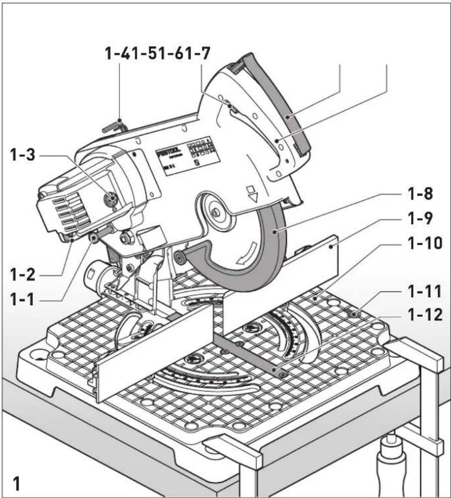
Head of Product Development

Ralf Brandt
Head of Product Conformity
1 Symbols....16
2 Safety warnings....16
3 Intended use 19
4 Technical data.... 19
5 Parts of the machine....19
6 Operation....19
7 Settings....20
8 Working with the machine.... 21
9 Service and maintenance....23
10 Accessories.... 24
11 Environment....24
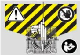
1 Symbols

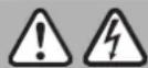
Warning of general danger

Read the operating instructions and safety instructions.

Danger area! Keep hands away!

Wear protective goggles.

Wear ear protection.

Wear a dust mask.

Wear protective gloves.

Do not dispose of it with domestic waste.

Tip or advice

Handling instruction

Safety class II

Electronics: Adjustable speed
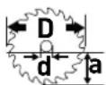
Saw blade dimensions
a ... Max. cutting depth
D ... Diameter
d ... Locating bore

Wood

Laminated wooden panels

Aluminium
Speed adjusting wheel

CE marking: Confirms the conformity of the power tool with the European Community directives.

Danger area! Do not remain in this area.
Danger area! Do not remain in this area.
2 Safety warnings
2.1 General power tool safety warnings
WARNING! Read all safety warnings, instructions, illustrations and specifications provided with this power tool. Failure to follow all instructions listed below may result in electric shock, fire and/or serious injury.
Save all warnings and instructions for future reference.
The term "power tool" in the warnings refers to your mains-operated (corded) power tool or battery-operated (cordless) power tool.
2.2 Machine-related safety notices
- Mitre saws are intended to cut wood or wood-like products, they cannot be used with abrasive cut-off wheels for cutting ferrous material such as bars, rods, studs, etc. Abrasive dust causes moving parts such as the lower guard to jam. Sparks from abrasive cutting will burn the lower guard, the kerf insert and other plastic parts.
- Use clamps to support the workpiece whenever possible. If supporting the workpiece by hand, you must always keep your hand at least 100 mm from either side of the saw blade. Do not use this saw to cut pieces that are too small to be securely clamped or held by hand. If your hand is placed too close to the saw blade, there is an increased risk of injury from blade contact.
- The workpiece must be stationary and clamped or held against both the fence and the table. Do not feed the workpiece into the blade or cut "freehand" in any way. Unrestrained or moving workpieces
could be thrown at high speeds, causing injury.
- Never cross your hand over the intended line of cutting either in front or behind the saw blade. Supporting the workpiece "cross handed" i.e. holding the workpiece to the right of the saw blade with your left hand or vice versa is very dangerous.
- Do not reach behind the fence with either hand closer than 100 mm from either side of the saw blade, to remove wood scraps, or for any other reason while the blade is spinning. The proximity of the spinning saw blade to your hand may not be obvious and you may be seriously injured.
- Inspect your workpiece before cutting. If the workpiece is bowed or warped, clamp it with the outside bowed face toward the fence. Always make certain that there is no gap between the workpiece, fence and table along the line of the cut. Bent or warped workpieces can twist or shift and may cause binding on the spinning saw blade while cutting. There should be no nails or foreign objects in the workpiece.
- Do not use the saw until the table is clear of all tools, wood scraps, etc., except for the workpiece. Small debris or loose pieces of wood or other objects that contact the revolving blade can be thrown with high speed.
- Cut only one workpiece at a time. Stacked multiple workpieces cannot be adequately clamped or braced and may bind on the blade or shift during cutting.
- Ensure the mitre saw is mounted or placed on a level, firm work surface before use. A level and firm work surface reduces the risk of the mitre saw becoming unstable.
- Plan your work. Every time you change the bevel or mitre angle setting, make sure the adjustable fence is set correctly to support the workpiece and will not interfere with the blade or the guarding system. Without turning the tool "ON" and with no workpiece on the table, move the saw blade through a complete simulated cut to assure there will be no interference or danger of cutting the fence.
- Provide adequate support such as table extensions, saw horses, etc. for a workpiece that is wider or longer than the table top. Workpieces longer or wider than the
mitre saw table can tip if not securely supported. If the cut-off piece or workpiece tips, it can lift the lower guard or be thrown by the spinning blade.
- Do not use another person as a substitute for a table extension or as additional support. Unstable support for the workpiece can cause the blade to bind or the workpiece to shift during the cutting operation pulling you and the helper into the spinning blade.
- The cut-off piece must not be jammed or pressed by any means against the spinning saw blade. If confined, i.e. using length stops, the cut-off piece could get wedged against the blade and thrown violently.
- Always use a clamp or a fixture designed to properly support round material such as rods or tubing. Rods have a tendency to roll while being cut, causing the blade to "bite" and pull the work with your hand into the blade.
- Let the blade reach full speed before contacting the workpiece. This will reduce the risk of the workpiece being thrown.
- If the workpiece or blade becomes jammed, turn the mitre saw off. Wait for all moving parts to stop and disconnect the plug from the power source and/or remove the battery pack. Then work to free the jammed material. Continued sawing with a jammed workpiece could cause loss of control or damage to the mitre saw.
- After finishing the cut, release the switch, hold the saw head down and wait for the blade to stop before removing the cut-off piece. Reaching with your hand near the coasting blade is dangerous.
2.3 Tools and tool parts
- Deformed or cracked saw blades and saw blades with blunt or broken cutting edges must not be used.
- Only use Festool saw blades that are designed for use in this power tool.
- Only use saw blades that are designed for at least the maximum speed of the saw.
- Use only saw blades recommended by the tool manufacturer, and suitable for sawing the materials to be cut. This prevents overheating of the saw teeth during sawing.
English
- Only transport the saw blade in suitable packaging. We recommend you use the original packaging.
2.4 Further safety instructions
- Only use saw blades that correspond to the specifications for intended use. Saw blades that do not fit correctly with the assembly parts will run unevenly and may cause fragments to break off from the material and be ejected. These fragments may hit the eyes of the user or any persons standing in the vicinity.
- Only use saw blades with a chip angle ≤slant 0^ . A chip angle >0^ will pull the saw into the workpiece. There is a risk of injury caused by saw kickback and the rotating workpiece.
- The power tool should only be used indoors and in a dry environment.
- Before each use, check that the pendulum guard is working correctly. Only use this power tool when it is in perfect working order.
- Never reach into the chip ejector with your hands. Rotating parts may injure your hands.
- Dust that is harmful to your health may be produced as you work (e.g. paint products containing lead and some types of wood). Contact with or inhalation of this dust may pose a risk for the operating personnel or persons in the vicinity. Observe the safety regulations that apply in your country.

Wear a P2 respiratory mask to protect health. In enclosed spaces, ensure there is sufficient ventilation and con-a mobile dust extractor.
- Replace any sawn-off or damaged limit stops. Damaged limit stops may be ejected when you work with the saw. Any persons standing in the vicinity of the saw may be injured.
- Only use original Festool accessories and consumables. Only accessories tested and approved by Festool are safe and perfectly adapted to the machine and application.
- Only for AS/NZS: The tool shall always be supplied via residual current device with a rated residual current of 30 mA or less.
2.5 Aluminium processing

When sawing aluminium, the following sures must be taken for safety reasons:
- Install an upstream residual-current circuit breaker (RCD, PRCD).
- Connect the power tool to a suitable dust extractor.
- Regularly clean dust deposits from the motor housing on the power tool.
- Use an aluminium saw blade.

Wear protective goggles.
2.6 Other risks
In spite of compliance with all relevant design regulations, dangers may still present themselves when the machine is operated, e.g.:
- Touching rotating parts from the side: Saw blade, clamping flange, flange screw,
- Touching live parts when the housing is open and the mains plug is still plugged in,
- Workpiece parts being thrown off,
- Parts of damaged tools being thrown off,
- Noise emissions,
- Dust emissions.
2.7 Emission levels
Levels determined in accordance with EN 62841 are typically:
Sound pressure level L _PA = 97 dB(A)
Sound power level L _WA = 104 dB(A)
Uncertainty K = 3 dB


CAUTION
Noise generated when working Risk of damage to hearing
▶ Use ear protection.
The specified noise emission values
– have been measured in accordance with a standardised test procedure, can be used to compare one power tool with another,
- and can also be used for a provisional assessment of the load.

CAUTION
Depending on how the power tool is used, particularly which type of workpiece is being machined, the noise emitted by the power tool during use may deviate from the specified values.
▶ To protect the operator, safety measures should be defined based on load estimates obtained under real conditions of use. (All parts of the operating cycle must be taken into account here, including, for example, times in which the power tool is switched off or when it is switched on but idling.)
3 Intended use
The power tool is a stationary unit designed for sawing strips of wood, plastic, aluminium profiles and similar materials. Do not use it to process other materials, in particular steel, concrete and mineral materials.
Only use Festool saw blades that are designed for use in this power tool.
The saw blades must comply with the following data:
- Saw blade diameter 216 mm - Cutting width 2,3 mm (corresponds to the tooth width)
- Locating bore 30 mm
- Standard blade thickness1,8 mm
– Saw blade in accordance with EN 847-1
- Saw blade with chip angle ≤slant 0^
Festool saw blades comply with EN 847-1.
Only saw materials for which the saw blade in question has been designed.

The user is liable for improper or non-in-tended use.
4 Technical data
Compound mitre saw SYM 70 RE
| Power 1150 W | |
| Speed (no-load) 2700 - | 5200 rpm |
| Mitre angle Interior angle 0° - 68° | ||
| Exterior angle 0° - 60° | ||
| Cutting range | Max. strip height | 70 mm |
| Max. strip width | 80 mm | |
Compound mitre saw SYM 70 RE
| Tool spindle dia. 30 mm | |
| Weight as per EPTA-Procedure 01:2014 | 9.6 kg |
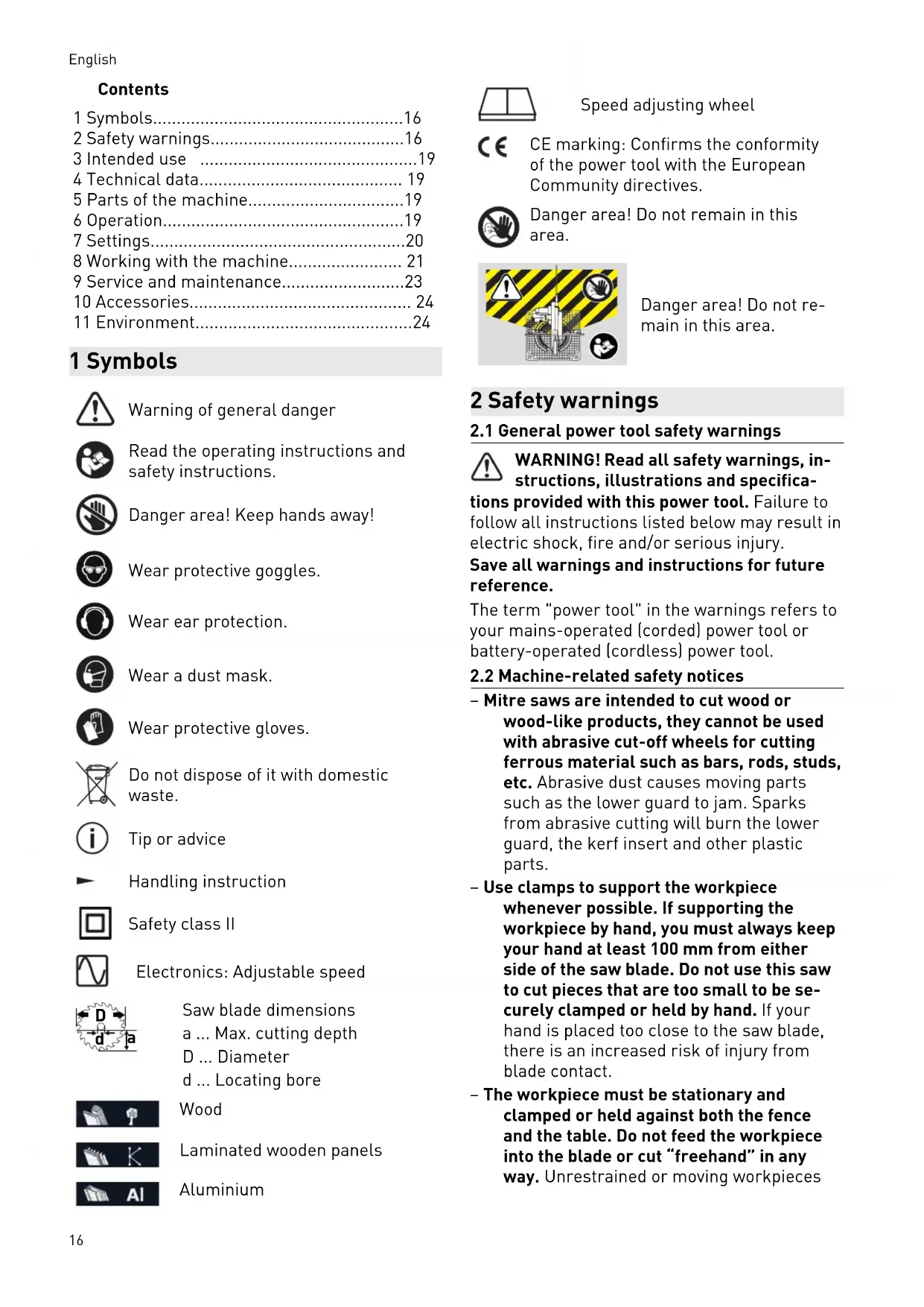
5 Parts of the machine
[1-1] Transport safety device
[1-2] Spindle lock
[1-3] Speed adjusting wheel
[1-4] Hexagon socket wrench
[1-5] On/off switch
[1-6] Release lever for saw unit
[1-7] Handle
[1-8] Pendulum guard
[1-9] Stop rulers
[1-10] Saw table
[1-11] Bracket for bevel
[1-12] Table top insert
The specified illustrations appear at the beginning of the Operating Instructions.
6 Operation

WARNING
Unauthorised voltage or frequency.
Risk of accidents
The mains voltage and the frequency of the power source must correspond to the specifications on the name plate.
▶ In North America, only Festool machines with the voltage specifications 120 V / 60 Hz may be used.
6.1 Initial commissioning
▶ Unlock the transport safety device [1-1] by pulling at the locking pin.
6.2 Setting up the machine

WARNING
Risk of injury, electric shock
▶ Always disconnect the mains plug from the socket before performing any work on the machine.
Before use install the machine on a flat and sturdy work surface (e.g. workbench).
You have the following installation options
Fastening clamps: Use fastening clamps to secure the machine to the work surface. The flat surfaces at the four support points on the saw table can be used as clamping surfaces.
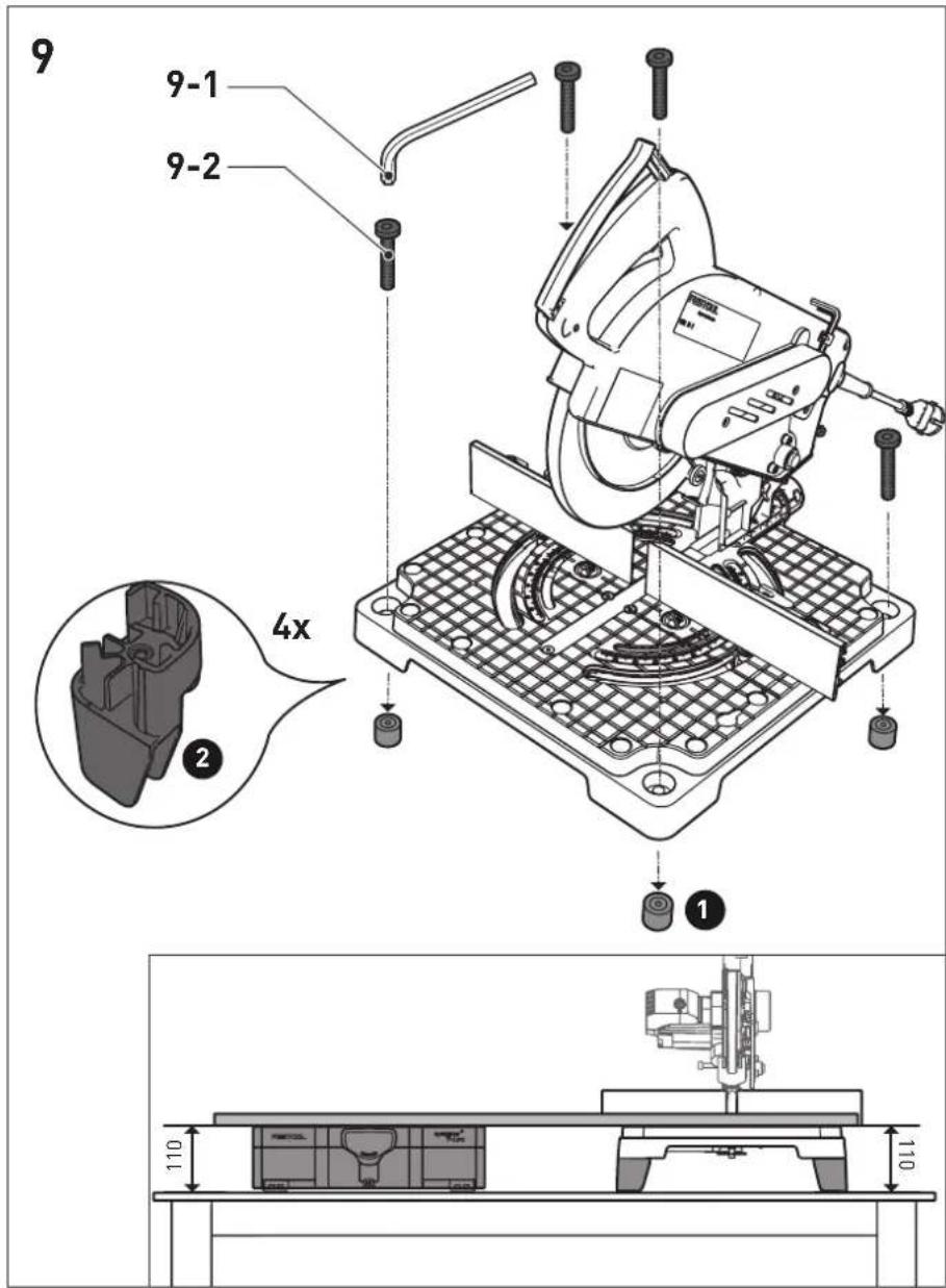
Installing raised legs (optional)
If you want to use a Systainer as an extended contact area, you first have to install the raised legs supplied with the machine in order to guarantee the same height of saw table and Systainer.
▶ Loosen the four screws [9-2] at the corners of the saw table with the hex key [9-1].
▶ ① Remove the four rubber legs.
▶ Install all four raised legs with the enclosed screws and tighten the screws.
WARNING! Ensure before working with the machine that all four raised legs have been securely installed and the machine is standing solidly on an even surface with the raised legs installed.
The screws from the rubber legs cannot be used for securing the raised legs.
6.3 Transportation
Securing the machine (transport position)
▶ Press the release lever for the saw unit [1-6].
▶ Swivel the saw unit down all the way to the stop.
▶ Press the transport safety device [1-1]. The saw unit will now remain in the lower position.
▶ Stow the hex key [1-4] and the bevel [4-2] in the intended holders and firmly clamp the workpiece clamp at the saw table [1-10].

WARNING
Risk of injury
▶ Never lift or carry the machine by the movable pendulum guard [1-8].
- When carrying the machine hold it at the side of the saw table [1-10] and at the handle [1-7].
▶ Always use two hands for lifting and carrying the machine.
6.4 Unlocking the machine (working position)
▶ Push the saw unit down slightly and pull the transport safety device [1-1].
▶ Swivel the saw unit upwards.
6.5 Switching on/off
▶ Press the release lever [1-6] until you feel the resistance in order to unlock the saw unit and the pendulum guard.
▶ Press the on/off switch [1-5] all the way in to switch on the machine.
▶ Release the on/off switch again to switch off the machine.
▶ Wait until the saw blade has come to a complete standstill and only then swivel the saw unit upwards.
7 Settings


WARNING
Risk of injury, electric shock
▶ Always disconnect the mains plug from the socket before performing any work on the machine.
7.1 Selecting the saw blade
Festool saw blades are identified by a coloured ring. The colour of the ring represents the material for which the saw blade is suited.
Symbol Saw blade Material
(Colour)

Fine tooth saw blade 216 x 2.3 x 30 W48
Wood (Yellow)

Special saw blade 216 x 2.3 x 30 W60
Aluminium (Blue)
7.2 Tool replacement

WARNING
Risk of injury
▶ Observe the following instructions:
- Disconnect the mains plug from the socket before changing tools.
- Only use the spindle stop [1-2] when the saw blade is at a standstill.
- The saw blade becomes very hot during operation; do not touch it before it has cooled down.
- Wear protective gloves due to the risk of injury from sharp blades while changing tools.
- Only use Festool saw blades that are designed for use in this power tool.
Removing the saw blade
▶ Move the machine into the working position.
▶ Hold down the spindle lock when unscrewing the screw [2-1].
▶ Fully loosen the screw [2-4] using the hex key [1-4] (left-hand thread).
▶ Press the release lever [2-2] of the pendulum guard.
▶ Fully open the pendulum guard [2-7].
▶ Remove the clamping flange [2-5] and the saw blade.
Fitting the saw blade
- Clean all parts before installing them (saw blade, flange, screw).
▶ Place the saw blade on the tool spindle.

WARNING
Risk of injury
▶ Make sure that the rotational directions of the saw blade [2-6] and the machine [2-3] correspond to each other.
▶ Press the spindle lock [2-1].
- Secure the saw blade with the clamping flange [2-5] and the screw [2-4].
▶ Firmly tighten the screw [2-4] (left-hand thread).
7.3 Dust extraction


WARNING
Health hazard posed by dust
▶ Always work with an extractor.
▶ Comply with national regulations.
▶ Wear a dust mask.
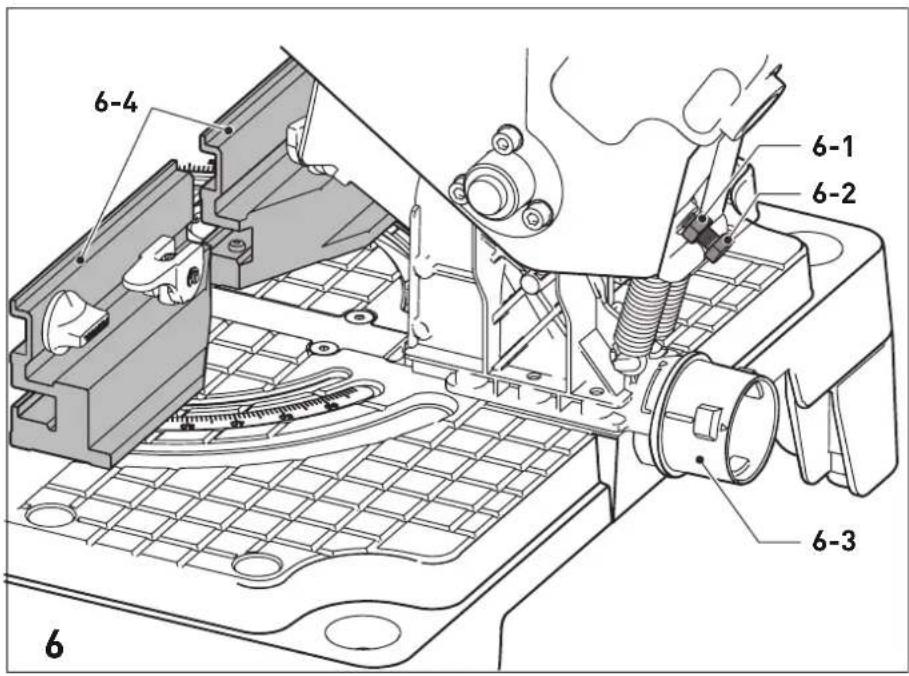
A Festool dust extractor with an extractor hose diameter of 36 mm or 27 mm (36 mm recommended due to the reduced risk of clogging) can be connected to the extractor connector.
[6-3]
- Disconnect the mains plug from the socket before installing the extractor hose.
- Secure the extractor hose at the extractor connector using a bayonet fitting [6-3].
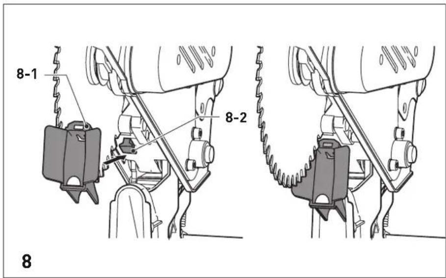
The chip deflector [8-1] improves the collection of dust and chips. Therefore, never work without a fitted chip deflector.
![FESTOOL SYM 70 RE - [6-3] - 1](/content/2026/04/594017/images/69c25fb811db6980f6955e2e4f78e8f5053ceabffa27f3e07722e724dc23155d.jpg)
CAUTION
Risk of injury at saw blade
- Avoid contact with the saw blade.
▶ Clamp the chip deflector at the bracket provided [8-2] by clicking it into the slot.
8 Working with the machine


WARNING
Flying tool parts/workpiece parts Risk of injury
▶ Wear protective goggles.
▶ Ensure that no other persons are close to the machine while it is being used.
▶ Always clamp workpieces tightly.
▶ The workpiece clamp must lie flat on the workpiece.

WARNING
The pendulum guard does not close Risk of injury
▶ Stop the sawing process.
▶ Unplug the mains cable and remove waste. In the event of damage, remove the pendulum guard.

WARNING
Risk of injury
▶ Observe the following instructions:
- Correct working position:
- At the front on the side of the operator;
- Head-on to the saw;
- Beside the line of cut.
- During operation, always hold the power tool tightly by the handle in your operating hand. Always keep your free hand outside of the hazardous area.
- Only guide the power tool towards the workpiece when it is switched on.
- Adjust the feed speed in order to prevent the machine from overloading and to prevent the plastic from melting if you are cutting plastics.
- Do not work on the power tool if its electronics are defective as this may lead to excessive speeds.
- Before beginning work, ensure that the saw blade cannot touch the stop rulers, work-piece clamp, fastening clamps or other machine parts.
Always disconnect the mains plug from the socket when the power tool is not in use. This optimises the service life of the electronics.
8.1 Check that the pendulum guard can move

The pendulum guard must always be able to move freely and close independently.
▶ Pull out the mains plug.
▶ Take hold of the pendulum guard and, as a trial run, swivel it into the saw unit.
The pendulum guard must be easy to move and must be almost fully lowered into the saw unit.
Cleaning the area of the saw blade
▶ Always keep the area around the pendulum guard clean.
▶ Clear dust and chippings by blowing out with compressed air or using a brush.
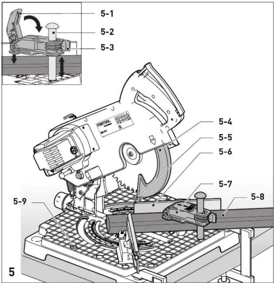
8.2 Workpiece clamp
Proceed as follows to insert the workpiece clamp
▶ Disconnect the mains plug from the socket before installing the workpiece clamp.
▶ Fit the workpiece clamp [5-7] into one of the holes [5-9]. The workpiece clamp must be in front of the workpiece.
8.3 Clamping the workpiece

WARNING
Risk of injury
▶ Observe the following instructions:
- Secure fit with workpiece clamp – always clamp the workpiece in position with the workpiece clamp. This requires the hold-down clamp to be resting securely on the workpiece. (Note: Aids may be required depending on the workpiece contours, e.g. round contours). Do not machine any workpieces that have not been securely clamped.
- Size – do not process workpieces that are too small. In the interests of safety, the cut piece remaining should be at least 30 mm long. Small workpieces may be pulled backwards by the saw blade and into the gap between the saw blade and the stop ruler. For safety reasons, the cut-off remaining piece should still be able to be clamped with the workpiece clamp.
- Take particular care that workpieces are not pulled backwards by the saw blade and into the gap between the saw blade and the stop ruler. The risk of this happening is especially high with horizontal mitre cuts.
Long workpieces
Provide extra support for any workpieces that protrude beyond the sawing surface.
▶ Use a Systainer as an additional contact area.
- Secure the workpiece with the workpiece clamp provided.
Thin workpieces
During sawing, thin workpieces may wobble or break.
▶ Reinforce the workpiece: Clamp it together with wood offcuts.
Proceed as follows to clamp the workpiece
- Place the workpiece on the saw table and push it against the stop rulers [1-9].
▶ Open the workpiece clamp [5-7] using the lever [5-1].
▶ Turn the rotary knob [5-3] counterclockwise to loosen the vertical position of the workpiece clamp.
▶ Lower the hold-down clamp onto the workpiece.
▶ Turn the rotary knob [5-3] clockwise to lock the vertical position of the workpiece clamp. - Close the workpiece clamp [5-7] using the lever [5-1].
8.4 Workpiece stop
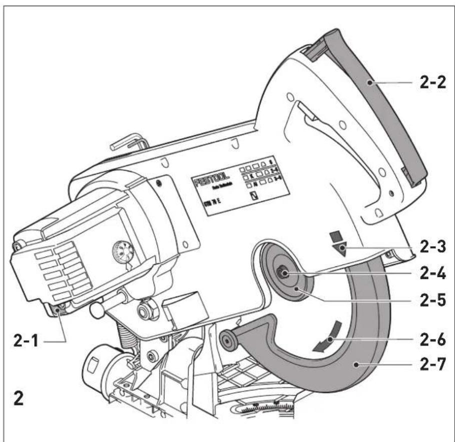
Adjusting the mitre angle
For mitre cuts, you must adjust the stop rulers [3-3] so that they do not impede the functionality of the pendulum guard or come into contact with the saw blade.
▶ Disconnect the mains plug from the socket before adjusting the stop rulers.
▶ Open the clamping lever [3-2].
▶ Set the required mitre angle.
▶ Close the clamping lever again.
Setting the stop rulers
▶ Disconnect the mains plug from the socket before adjusting the stop rulers.
▶ Unscrew the rotary knobs [3-1].
▶ Push the stop rulers [3-3] as close as possible to the saw blade, however without making contact.
▶ Tighten the rotary knobs [3-1].
8.5 Speed control
The speed can be continuously adjusted between 2700 and 5200 rpm using the adjusting wheel [1-3]. This enables you to optimise the cutting speed to suit each material.
Recommended position of the adjusting wheel
Wood 3 - 6
Plastic 3 - 5
Fibre materials 1 - 3
Aluminium and non-ferrous profiles 3 - 6
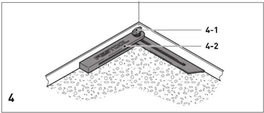
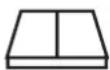
8.6 Bevel
The bevel [4-2] can be used to gauge any angle (e.g. between two walls). The bevel therefore forms the angle bisection.
Gauging the interior angle
▶ Open the clamp [4-1].
- Place the bevel with the two routers [4-2] against the interior angle.
▶ Close the clamp [4-1].
Gauging the exterior angle
▶ Open the clamp [4-1].
- Place the bevel with the two routers [4-2] against the exterior angle.
▶ Close the clamp [4-1].
Transferring the angle
▶ Open the clamp lever [3-2] at the stop rulers [3-3].
▶ Position the bevel on the saw table.
▶ Position the two stop rulers at the bevel.
- Close the clamp lever [3-2] at the stop rulers.
8.7 Sawing strips
▶ Adjust the machine settings to the settings you would like.
▶ Position the workpiece [5-8] at a stop ruler [5-6].
▶ Clamp the workpiece in position using the workpiece clamp [5-7].
▶ Switch on the machine.
▶ Slowly guide the saw unit downwards by the handle.
▶ Push the saw unit downwards at an even feed rate and saw the workpiece.
▶ Switch off the machine.
- Wait until the saw blade has come to a complete standstill and only then swivel the saw unit upwards.
9 Service and maintenance
WARNING
Risk of injury, electric shock
▶ Always pull the mains plug from the socket before performing any servicing and maintenance work.
▶ All maintenance and repair work which requires the motor housing to be opened should always be carried out by an authorised service workshop.

Customer service and repairs must only be carried out by the manufacturer or service workshops. Find the nearest address at:
www.festool.co.uk/service
Always use original Festool spare parts. Order no. at:
www.festool.co.uk/service
▶ Damaged safety devices and components must be repaired or replaced in a recognised specialist workshop, unless otherwise indicated in the operating instructions.
▶ Regularly clean the table top insert [1-12] as well as the extraction channel of the chip deflector [8-1] to remove wood chips, dust deposits and remains of workpieces.
▶ To ensure constant air circulation, always keep the cooling air openings in the housing clean and free of blockages.
9.1 Replacing the table top insert
Do not work with a worn-out table top insert [1-12]; replace it with a new one instead.
- When replacing the table top insert, loosen the five screws which secure the table top insert onto the saw table.
A new table top insert is supplied without a kerf. Therefore, you have to cut a notch first after the installation.
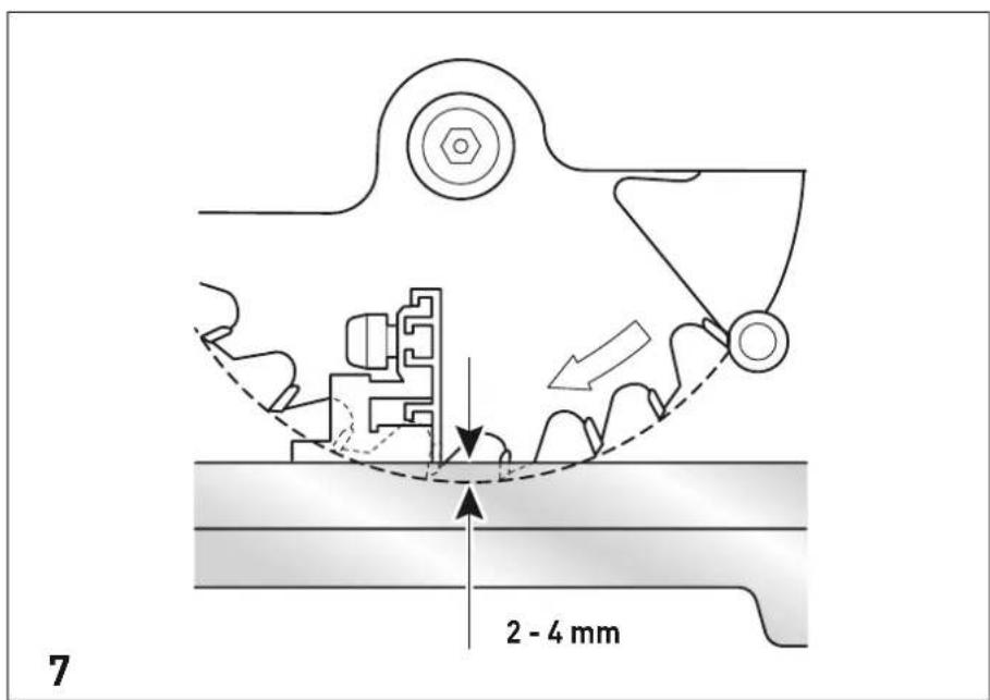
9.2 Readjusting the saw unit
Using the screw [6-2] you can set the swivel range of the saw unit. This may be necessary if the diameter of the saw blade changed when resharpening or a new saw blade is inserted.
▶ Set the stop rulers [6-4] to 0°.
▶ Loosen the locknut [6-1].
▶ Swivel the saw unit down all the way to the stop.
▶ Turn the screw [6-2] to adjust the saw unit as shown in the picture 7 (left-hand turn -
English
saw unit is lowered; right-hand turn - saw unit is raised).
▶ Retighten the locknut [6-1].
10 Accessories
Use only original Festool accessories.
Refer to the Festool catalogue for the order numbers of accessories and tools or find them online at www.festool.co.uk.
In addition to the accessories described,
Festool also provides a comprehensive range of system accessories that allow you to use your saw more effectively and in diverse applications, e.g.:
- Saw blades for different materials.
11 Environment

Do not dispose of the device in the household waste! Recycle devices, accessories and packaging. Observe applicable national regulations.
EU only: In accordance with the European Directive on waste electrical and electronic equipment and implementation in national law, used power tools must be collected separately and handed in for environmentally friendly recycling.
Information on REACH: www.festool.co.uk/reach