TKS 80 EBS - Saw FESTOOL - Free user manual and instructions
Find the device manual for free TKS 80 EBS FESTOOL in PDF.
| Product type | Transportable stationary table circular saw |
| Brand | Festool |
| Model | TKS 80 EBS |
| Power consumption | 2200 W (EU/UK), 1900 W (CH/ZA), 2000 W (DK/AUS) |
| Idle speed | 1700 - 3500 rpm (adjustable) |
| Cutting height | 0 - 80 mm (at 90°), 0 - 56 mm (at 45°), 0 - 54 mm (at 47°) |
| Tilt angle | -2° to 47° |
| Table dimensions | 690 x 580 mm |
| Table height (unfolded / folded) | 900 mm / 385 mm |
| Weight | 37.0 kg (according to EPTA 01:2014) |
| Saw blade diameter | 254 mm |
| Bore | 30 mm |
| Cutting width (kerf) | > 2.2 mm |
| Blade base thickness | < 1.8 mm |
| Safety | SawStop-AIM technology (skin contact stop), electrodynamic brake, anti-restart protection |
| Electronics | Soft start, speed regulation, load limiter, thermal fuse |
| Dust extraction connection | Upper Ø 27 mm, lower Ø 36 mm (bayonet) |
| Workable materials | Wood, laminated panels, non-ferrous metals, plastics |
| Transport | Integrated transport wheels, side grip areas |
| Included accessories | Click-in miter fence, blade guard with riving knife, riving knife for grooving, SawStop cartridge, push stick, wrenches, power cable |
| Maintenance | Regular cleaning of dust deposits, replacement of auto-cut carbon brushes |
| Country of manufacture | Germany (Festool brand) |
| Warranty | Manufacturer's warranty (see Festool conditions) |
Frequently Asked Questions - TKS 80 EBS FESTOOL
User questions about TKS 80 EBS FESTOOL
0 question about this device. Answer the ones you know or ask your own.
Ask a new question about this device
Download the instructions for your Saw in PDF format for free! Find your manual TKS 80 EBS - FESTOOL and take your electronic device back in hand. On this page are published all the documents necessary for the use of your device. TKS 80 EBS by FESTOOL.
USER MANUAL TKS 80 EBS FESTOOL
Declaration of Conformity
We as the manufacturer Festool GmbH, Wertstraße 20, 73240 Wendlingen, Germany declare under our sole responsibility that the product(s):
Designation:
Designation of Type(s):
Serial number(s) 1:
Bench-mounted circular saw
TKS 80 EBS
10179652
fulfills all the relevant provisions of the following UK Regulations:
S.I. 2008/1597
S.I. 2016/1091
S.I. 2012/3032
Supply of Machinery (Safety) Regulations 2008
Electromagnetic Compatibility Regulations 2016
Restriction of the Use of Certain Hazardous Substances in Electrical
and Electronic Equipment Regulations 2012
and are manufactured in accordance with the following designated standards:
BS EN 62841-1:2015
BS EN 62841-3-1:2014+A11:2017
BSEN55014-1:2017
BSEN55014-2:2015
BS EN IEC 61000-3-2:2019
BSEN61000-3-3:2013
BS EN IEC 63000:2018
11 in the specified serial number range (S-Nr.) from 40000000 - 49999999

Place and date of declaration: Wendlingen, 15.04.2021
Signed on behalf of and in name of Festool GmbH

Markus Stark
Head of Product development
i. V. Q. Orrorth
Ralf Brandt
Head of Productconformity
Tischkreissage Bench-mounted circular saw Scie stationnaire
Head of Product Development
Ralf Brandt
Head of Product Conformity
1 Symbols 27
2 Safety warnings. 27
3 Intended use 31
4 Technical data. 32
5 Parts of the device. 32
6 Set-up/start-up 32
7 Transportation. 34
8 SawStop AIM technology. 34
9 Additional settings/functions. 37
10 Working with the electric power tool....41
11 Storage 43
12 Service and maintenance. 43
13 Accessories 44
14 Environment. 44
15 General information. 44
1 Symbols

Warning of general danger

Warning of electric shock

Read the operating instructions and safety instructions.

Wear ear protection.

Wear a dust mask.

Wear protective gloves.

Wear protective goggles.

Do not remove the sticker.

Direction of rotation of saw and the saw blade


Wood


Laminate, mineral materials


Aluminium, plastic

Adjustment marking for storing the preset profile setting rail

Handle area

Position markings for sliding table plastic holders

SawStop AIM technology

Saw blade diameter

Cutting width and standard blade thickness
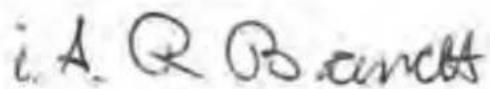
When sawing cutting widths of ≤slant 3mm the SawStop AIM technology is triggered or the TKS 80 EBS does not start.

The saw blade and cartridge must not touch!

Electronics with adjustable, constant speed and temperature monitoring

Electro-dynamic run-down brake

CE marking: Confirms the conformity of the power tool with the European Community directives.

UKCA marking: The United Kingdom Conformity Assessed symbol is a marking for products being placed on the market in the United Kingdom. It is a manufacturers indication that the product is in conformance with the relevant regulations in the UK.

Do not dispose of it with domestic waste.

Tip or advice

Handling instruction
2 Safety warnings
2.1 General power tool safety warnings

WARNING! Read all safety warnings, instructions, illustrations and specifica
tions provided with this power tool. Failure to follow all instructions listed below may result in electric shock, fire and/or serious injury.
Save all warnings and instructions for future reference.
The term "power tool" in the warnings refers to your mains-operated (corded) power tool or battery-operated (cordless) power tool.
2.2 Safety warnings for bench-mounted circular saws
1) Guarding related warnings
-
Keep guards in place. Guards must be in working order and be properly mounted. A guard that is loose, damaged, or is not functioning correctly must be repaired or replaced.
-
Always use saw blade guard, riving knife and anti-kickback device for every through-cutting operation. For through-cutting operations where the saw blade cuts completely through the thickness of the workpiece, the guard and other safety devices help reduce the risk of injury.
-
Immediately reattach the guarding system after completing an operation (such as rabbeting, dadoing or resawing cuts) which requires removal of the guard, riv ing knife and/or anti-kickback device. The guard, riving knife, and anti-kickback device help to reduce the risk of injury.
-
Make sure the saw blade is not contacting the guard, riving knife or the workpiece before the switch is turned on. Inadvertent contact of these items with the saw blade could cause a hazardous condition.
-
Adjust the riving knife as described in this instruction manual. Incorrect spacing, positioning and alignment can make the riving knife ineffective in reducing the likelihood of kickback.
-
For the riving knife and anti-kickback device to work, they must be engaged in the workpiece. The riving knife and anti-kickback device are ineffective when cutting workpieces that are too short to be engaged with the riving knife and anti-kickback device. Under these conditions a kickback cannot be prevented by the riving knife and anti-kickback device.
-
Use the appropriate saw blade for the riving knife. For the riving knife to function properly, the saw blade diameter must match the appropriate riving knife and the body of the saw blade must be thinner than the thickness of the riving knife and the cutting width of the saw blade must be wider than the thickness of the riving knife.
2) Cutting procedures warnings

DANGER: Never place your fingers ends in the vicinity or in line with the
saw blade. A moment of inattention or a slip could direct your hand towards the saw blade and result in serious personal injury.
- Feed the workpiece into the saw blade or cutter only against the direction of rotation. Feeding the workpiece in the same direction that the saw blade is rotating above the table may result in the workpiece, and your hand, being pulled into the saw blade.
- Never use the mitre gauge to feed the workpiece when ripping and do not use the rip fence as a length stop when cross cutting with the mitre gauge. Guiding the workpiece with the rip fence and the mitre gauge at the same time increases the likelihood of saw blade binding and kickback.
- When ripping, always apply the workpiece feeding force between the fence and the saw blade. Use a push stick when the distance between the fence and the saw blade is less than 150mm , and use a push block when this distance is less than 50 mm. "Work helping" devices will keep your hand at a safe distance from the saw blade.
- Use only the push stick provided by the manufacturer or constructed in accordance with the instructions. This push stick provides sufficient distance of the hand from the saw blade.
- Never use a damaged or cut push stick. A damaged push stick may break causing your hand to slip into the saw blade.
- Do not perform any operation "freehand". Always use either the rip fence or the mitre gauge to position and guide the workpiece. "Freehand" means using your hands to support or guide the workpiece, in lieu of a rip fence or mitre gauge. Freehand sawing leads to misalignment, binding and kickback.
- Never reach around or over a rotating saw blade. Reaching for a workpiece may lead to accidental contact with the moving saw blade.
- Provide auxiliary workpiece support to the rear and/or sides of the saw table for long and/or wide workpieces to keep them level. A long and/or wide workpiece has a tendency to pivot on the table's edge, causing loss of control, saw blade binding and kickback.
- Feed workpiece at an even pace. Do not bend or twist the workpiece. If jamming occurs, turn the tool off immediately, un
plug the tool then clear the jam. Jamming the saw blade by the workpiece can cause kickback or stall the motor.
- Do not remove pieces of cut-off material while the saw is running. The material may become trapped between the fence or inside the saw blade guard and the saw blade pulling your fingers into the saw blade. Turn the saw off and wait until the saw blade stops before removing material.
- Use an auxiliary fence in contact with the table top when ripping workpieces less than 2mm thick. A thin workpiece may wedge under the rip fence and create a kickback.
3) Kickback causes and related warnings
Kickback is a sudden reaction of the workpiece due to a pinched, jammed saw blade or mis-aligned line of cut in the workpiece with respect to the saw blade or when a part of the workpiece binds between the saw blade and the rip fence or other fixed object.
Most frequently during kickback, the workpiece is lifted from the table by the rear portion of the saw blade and is propelled towards the operator.
Kickback is the result of saw misuse and/or incorrect operating procedures or conditions and can be avoided by taking proper precautions as given below.
- Never stand directly in line with the saw blade. Always position your body on the same side of the saw blade as the fence.
Kickback may propel the workpiece at high velocity towards anyone standing in front and in line with the saw blade. - Never reach over or in back of the saw blade to pull or to support the workpiece.
Accidental contact with the saw blade may occur or kickback may drag your fingers into the saw blade. - Never hold and press the workpiece that is being cut off against the rotating saw blade. Pressing the workpiece being cut off against the saw blade will create a binding condition and kickback.
- Align the fence to be parallel with the saw blade. A misaligned fence will pinch the workpiece against the saw blade and create kickback.
- Use a featherboard to guide the workpiece against the table and fence when making non-through cuts such as rabbeting, dado
ing or resawing cuts. A featherboard helps to control the workpiece in the event of a kickback.
- Use extra caution when making a cut into blind areas of assembled workpieces. The protruding saw blade may cut objects that can cause kickback.
- Support large panels to minimise the risk of saw blade pinching and kickback. Large panels tend to sag under their own weight. Support(s) must be placed under all portions of the panel overhanging the table top.
- Use extra caution when cutting a workpiece that is twisted, knotted, warped or does not have a straight edge to guide it with a litre gauge or along the fence. A warped, knotted, or twisted workpiece is unstable and causes misalignment of the kerf with the saw blade, binding and kickback.
- Never cut more than one workpiece, stacked vertically or horizontally. The saw blade could pick up one or more pieces and cause kickback.
- When restarting the saw with the saw blade in the workpiece, centre the saw blade in the kerf so that the saw teeth are not engaged in the material. If the saw blade binds, it may lift up the workpiece and cause kickback when the saw is restarted.
- Keep saw blades clean, sharp, and with sufficient set. Never use warped saw blades or saw blades with cracked or broken teeth. Sharp and properly set saw blades minimise binding, stalling and kickback.
4) Table saw operating procedure warnings
- Turn off the table saw and disconnect the power cord when removing the table insert, changing the saw blade or making adjustments to the riving knife or saw blade guard, and when the machine is left unattended. Precautionary measures will avoid accidents.
- Never leave the table saw running unattended. Turn it off and don't leave the tool until it comes to a complete stop. An unattended running saw is an uncontrolled hazard.
- Locate the table saw in a well-lit and level area where you can maintain good footing
English
and balance. It should be installed in an area that provides enough room to easily handle the size of your workpiece. Cramped, dark areas, and uneven slippery floors invite accidents.
- Frequently clean and remove sawdust from under the saw table and/or the dust collection device. Accumulated sawdust is combustible and may self-ignite.
- The table saw must be secured. A table saw that is not properly secured may move or tip over.
- Remove tools, wood scraps, etc. from the table before the table saw is turned on. Distraction or a potential jam can be dangerous.
- Always use saw blades with correct size and shape (diamond versus round) of arbour holes. Saw blades that do not match the mounting hardware of the saw will run off-centre, causing loss of control.
- Never use damaged or incorrect saw blade mounting means such as flanges, saw blade washers, bolts or nuts. These mounting means were specially designed for your saw, for safe operation and optimum performance.
- Never stand on the table saw, do not use it as a stepping stool. Serious injury could occur if the tool is tipped or if the cutting tool is accidentally contacted.
- Make sure that the saw blade is installed to rotate in the proper direction. Do not use grinding wheels, wire brushes, or abrasive wheels on a table saw. Improper saw blade installation or use of accessories not recommended may cause serious injury.
2.3 Further safety instructions


Wear suitable personal protective equipment: Ear protection, protective goggles, dust mask for work that generates dust and protective gloves for changing tools.
- Faults on the power tool, including the separating guards or the tool, must be reported to maintenance staff immediately. The machine must not be used until the fault has been eliminated.
- Check the plug and cable on a regular basis and, if they are damaged, have them re
placed by an authorised customer service workshop.
- Use of your own aids e.g. rulers, etc. is not permitted.
- Only for AS/NZS: The tool shall always be supplied via residual current device with a rated residual current of 30mA or less.
2.4 Safety instructions for the pre-assembled saw blade
Usage
- The maximum speed specified on the saw blade must not be exceeded and the speed range must be adhered to.
- The pre-installed saw blade is only designed for use in circular saws.
- Proceed with extreme care when unpacking, packing and handling the tool (e.g. installing it in the machine). There is a risk of injury from extremely sharp cutting edges!
- When handling the tool, wearing safety gloves provides a more secure hold of the tool and further reduces the risk of injury.
- Circular saw blades with cracked bodies must be replaced. Repair is not permitted.
- Circular saw blades with a combination design (soldered saw teeth) with saw tooth thickness smaller than 1mm must no longer be used.
- WARNING! Do not use tools with visible cracks or blunt or damaged cutting edges.
Installation and mounting
- Tools must be clamped in such a way that they cannot come loose during operation.
- When assembling the tools, it must be ensured that the clamping takes place on the tool hub or the clamping surface of the tool, and that the cutting edges do not come into contact with other components.
- Do not lengthen the key or tighten by hitting with a hammer.
- The clamping surfaces must be cleaned to remove contamination, grease, oil and water.
- Clamping screws must be tightened according to the manufacturer's instructions.
- Only securely installed rings, e.g. rings that have been pressed in or those that are held in position by an adhesive bond, may be used to adjust the hole diameter of circular saw blades to the spindle diameter of the machine. The use of loose rings is not permitted.
Service and maintenance
- Repairs and sanding work may only be carried out by Festool customer service workshops or experts.
- The tool design must not be changed.
- Deresinify and clean the tool regularly [cleaning agent with pH between 4.5 and 8].
- Blunt edges can be resharpened on the clamping surface to a minimum cutting edge thickness of 1mm .
- Only transport the tool in suitable packaging - risk of injury!
2.5 Aluminium processing

When sawing aluminium, the following measures must be taken for safety reasons:
- Install an upstream residual-current circuit breaker (RCD, PRCD).
- Connect the power tool to a suitable dust extractor.
- Regularly clean dust deposits from the motor housing on the power tool.
- Use an aluminium saw blade.

Wear protective goggles.
2.6 Other risks
In spite of compliance with all relevant design regulations, dangers may still present themselves when the machine is operated, e.g.:
- Touching rotating parts from the side: Saw blade, clamping flange, flange screw,
- Touching live parts when the housing is open and the mains plug is still plugged in,
-Workpiece parts being thrown off, - Parts of damaged tools being thrown off,
- Noise emissions,
Dust emissions.
2.7 Emission levels
The levels determined in accordance with EN 62841 are typically:
Sound pressure level L P_A = 87 dB(A)
Sound power level L WA = 102 dB(A)
Uncertainty K = 3 dB

CAUTION
Noise generated when working
Risk of damage to hearing
Use ear protection.
The specified noise emission values
have been measured in accordance with a standardised test procedure, can be used to compare one power tool with another,
- and can also be used for a provisional assessment of the load.

CAUTION
The emission values may deviate from the specified values. This is dependent on how the tool is used and the type of workpiece being machined.
The actual load during the entire operating cycle must be evaluated.
Depending on the actual load, suitable protective measures must be defined in order to protect the operator.
3 Intended use
The TKS 80 EBS is designed as a transportable power tool for sawing wood, laminated wooden panels, non-ferrous metals and plastic.

NOTICE
SawStop AIM technology is triggered
- When sawing non-ferrous metals, wet, statically charged or conductive materials, deactivate the SawStop AIM technology (by-pass mode).
This power tool may only be used by experts or instructed persons.

The user is liable for improper or non-intended use.
3.1 Saw blades
Only use Festool saw blades that are designed for use in this power tool.
-Saw blade dimensions: 254× 30× 2.4mm
- Cutting width > 2.2 mm (corresponds to the kerf width)
- Locating bore, dia. 30 mm
- Standard blade thickness < 1.8 mm
-Sawblade with chip angle of ≥slant 15^
- Suitable for speeds of 3500 rpm or above
Festool saw blades comply with EN 847-1.
Only saw materials for which the saw blade in question has been designed.
Saw blades made of high-alloy high-speed steel (HSS steel) and grooving saw blades must not be used.
3.2 Cartridges
Only use Festool cartridges that are designed for use in this power tool.
4 Technical data
| Bench-mounted circular saw TKS 80 EBS | ||
| Power | ||
| TKS 80 EBS 220-240 V | EU (without DK), GB | 2200 W |
| TKS 80 EBS 230 V | CH, ZA | 1900 W |
| TKS 80 EBS 230 V | DK, AUS | 2000 W |
| Speed (no-load) 1700-3500 rpm | ||
| Locating bore Dia. 30 mm | ||
| Cutting height at 90°/45°/47° 0-80 mm/0-56 mm/0-54 mm | ||
| Inclination angle -2°-47° | ||
| Table dimensions (L x W) 690 x 580 mm | ||
| Table height, legs unfolded 900 mm | ||
| Table height, legs folded away 385 mm | ||
| Weight as per EPTA procedure 01:2014 37.0 kg | ||
5 Parts of the device
[1-1] Accessory holder
[1-2] Side handle areas
[1-3] 4V-profiles
[1-4] Spacer wedge for grooving
[1-5] Table insert
[1-6] Spacer wedge with guard support
[1-7] Guard
[1-8] Safety sticker
[1-9] Preset profile setting rail
[1-10] Fine adjustment
[1-11] Inclination angle setting
[1-12] Rotary knobs for foldaway legs
[1-13] Scale
[1-14] Cutting height setting
[1-15] Angle indicator
[1-16] Push stick holder
[1-17] Foldaway legs
[1-18] Closing flap
[1-19] Switch panel
[1-20] Transport rollers
[1-21] Shipping protection
The illustrations specified are located at the beginning and end of the operating instructions.
6 Set-up/start-up

CAUTION
Heavy transport packaging with bench-mounted circular saw
Risk of injury
The transport packaging with the bench-mounted circular saw must be carried and unpacked by two people.
6.1 Setting up the TKS 80 EBS
WARNING
Unauthorised voltage or frequency
Risk of accidents
The mains voltage and the frequency of the power source must correspond to the specifications on the name plate.
Before each use of the power tool, check the power cable and the mains plug. Any damage must only be rectified by a specialist workshop.
For use outdoors, only use the approved extension cable and cable connections.

WARNING
Power tool tips over on uneven ground Risk of accidents
- Ensure that the power tool is securely positioned.
The floor must be level, with a max. gradient of 10^ , and free of loose objects (e.g. chips and offcuts).
Foldaway legs


CAUTION
Crushing injuries to hands or fingers when folding the foldaway legs in or out
Wear protective gloves.
- Open the rotary knobs for the foldaway legs [1-12] as far as they will go.
- Fold the foldaway legs [1-17] out or in.
Screw in the rotary knobs for the foldaway legs [1-12] tight.
If the TKS 80 EBS wobbles, the length of a leg can be adjusted by turning the end cap [1-18] until the machine stands securely.
Removable legs

WARNING
Risk of accidents due to tilting power tool
Always use the removable legs together with an extension table or a sliding table.
- Not included in the scope of delivery.
6.2 Prior to commissioning
- Remove all packaging material, including packaging material underneath the table.
Pull out the shipping protection [1-21]. - Remove the safety sticker [1-8].
- Remove the pre-installed spacer wedge for grooving [1-4] (see section 9.8) and store it in the accessory holder [1-1].
If necessary, replace the pre-installed universal saw blade with a saw blade for the material to be sawed (see section 9.11).
Fit the spacer wedge with guard (see section 9.8).
Fit the preset profile setting rail (see section 9.5).
6.3 Switching on/off


WARNING
SawStop AIM technology only works with protective conductor terminal and with connected, earthed power source
Risk of injury
- Make sure that power is not supplied via the SYS-PST 1500 or a transformer, for example.

NOTICE
SawStop AIM technology is triggered
- Only switch on the TKS 80 EBS if the saw blade is not in contact with the workpiece, accessories or other objects.
Only use accessories intended for the TKS 80 EBS.
Warming phase
Electronics too cold: Ambient temperatures of < 5^ may delay the start of the TKS 80 EBS.
Try starting again after a few minutes.
Switching on
To switch on the machine, press the green main switch [2-1].
The green LED [2-4] lights up constantly. The red LED [2-5] flashes slowly.
The TKS 80 EBS is carrying out a self-check.
Wait until the status of the LEDs changes. The green LED [2-4] lights up constantly.
The red LED [2-5] is not lit.
The TKS 80 EBS is in standby mode.
Press the green START button [2-3]
The TKS 80 EBS is operational. SawStop AIM technology is activated.


WARNING
SawStop AIM technology is not triggered
- Only touch the saw blade when the machine has come to a complete standstill if there is a power failure or drop in voltage after switching it on.
Switching off
- To switch off sawing mode, press the red STOP button [2-2].
The green LED [2-4] flashes rapidly.
The red LED [2-5] is not lit.
English
Wait until the saw blade has come to a stop.

NOTICE
SawStop AIM technology is triggered
- Do not touch the saw blade when it is coming to a stop. The SawStop AIM technology is still active and is triggered upon contact.
The green LED [2-4] lights up constantly.
The red LED [2-5] is not lit.
The TKS 80 EBS is in standby mode.
Press the green main switch [2-1].
The TKS 80 EBS is non-operational.
7 Transportation

CAUTION
Heavy bench-mounted circular saw Risk of injury
The bench-mounted circular saw must be carried by two people.
- Hold it by the handle areas on the side [3-3] for transport. Never take hold of and transport the power tool by the guard.
- Store the accessories included in the scope of delivery in the accessory holders or the brackets provided for that purpose (Fig. 3a, 3b, 3c).
Accessory holder
Spacer wedge with guard [3-1]
Spacer wedge for grooving [3-2]
Cartridge [3-4]
Push stick [3-5]
Preset profile setting rail [3-7]
(Take note of the adjustment markings [3-6] for storing the preset profile setting rail.)
Power cable
Power cable brackets [3-8]
Power cable [3-9]
Tool
Hex key [3-10]
Spanner for the spindle flange [3-11]
Spanner for the spindle nut [3-12]
-
Remove accessories not included in the scope of delivery.
-
Fold in the foldaway legs (see section 6.1).
The TKS 80 EBS can be transported.
7.1 Transport rollers
The TKS 80 EBS is equipped with transport rollers [1-20] for moving it over short distances.
Hold the TKS 80 EBS by the handle areas on the side [1-2] and pull it into the required position.
8 SawStop AIM technology
The SawStop AIM technology can prevent the most serious cutting injuries.
The core component of the SawStop AIM technology is a cartridge that drives an aluminium block into the saw blade with the aid of a spring. The mechanism is triggered by a capacitative sensor when it comes into contact with human skin or any other conductive materials during operation.
The SawStop AIM technology only works with a protective earth connection and an earthed power source. Make sure that power is not supplied via the SYS PowerStation or a transformer, for example.

Working with the TKS 80 EBS is only possible if the cartridge is inserted.

WARNING
Noise generated when the SawStop AIM technology is triggered
Risk of accidents
Use ear protection.

NOTICE
SawStop AIM technology is triggered
- Do not let the saw blade come into contact with the stopper or the cross stop.

NOTICE
SawStop AIM technology is triggered or the TKS 80 EBS does not start.
Distance between saw blade and fence too small.
- When sawing cutting widths of ≤slant 3mm , use a support ≥slant 19mm .
8.1 Function monitoring
The SawStop AIM technology continuously monitors the regular operation of the saw. The LED lights show the current operating status.
LED status in standby
| □ | The green LED [2-4] lights up constantly. | The bench-mounted circular saw starts up in approx. 10 seconds. |
| □ | The red LED [2-5] flash- es slowly. | |
| □ | The green LED [2-4] lights up constantly. | The bench-mounted circular saw is ready to use and is in stand- by mode. |
| □ | The red LED [2-5] is not lit. | |
| □ | The green LED [2-4] flash- es rapidly. | Restart protection When activating by- pass mode, the yellow SawStop AIM switch was released too early. →To rectify the fault, press the red STOP button. |
| □ | {alternating} | |
| □ | The red LED [2-5] flash- es rapidly. | |
| □ | The green LED [2-4] lights up constantly. | Contact with the saw blade in standby. →Remove the contact trigger and wait approx. 5 seconds until the fault is rectified. Or: Distance between saw blade and fence too small. →When sawing cutting widths of ≤ 3 mm, use a sup- port ≥ 19 mm. |
| □ | The red LED [2-5] flash- es rapidly. |
| □ | The green LED [2-4] is not lit. | Cartridge locking device fault. Switch off the bench-mounted circular saw and check the cartridge locking device. |
| The red LED [2-5] flash- es slowly. | ||
| □ | The green LED [2-4] flash- es slowly. | Saw blade missing or too small. Switch off the bench-mounted circular saw and insert a suitable saw blade (see section 3). |
| The red LED [2-5] lights up constantly. | ||
| □ | The green LED [2-4] is not lit. | Replace the car- tridge. Switch off the bench-mounted cir- cular saw. If the fault is still not rectified, insert a new car- tridge. Or: Electronics too cold: Warming phase at ambient tempera- tures < 5 °C. Try starting again after a few mi- nutes. |
| The red LED [2-5] lights up constantly. |
LED status during operation
| The green LED [2-4] flash- es rapidly. | The saw blade comes to a stop. ① The SawStop AIM technology is active and is triggered upon contact. |
| The red LED [2-5] is not lit. | |
| The green LED [2-4] flash- es slowly. | Activated bypass mode. |
| The red LED [2-5] is not lit. | |
| The green LED [2-4] flash- es slowly. | Contact with the saw blade while bypass mode is activated |
| The red LED [2-5] flash- es rapidly. | The fault is rectified if the saw blade comes to a stop. |
LED status in standby or during operation
| □ | The green LED [2-4] is not lit. | Workpiece too damp. Switch off the bench-mounted circular saw and dry the workpiece or continue sawing in bypass mode. |
| The red LED [2-5] flash-es rapidly. |
| The green LED [2-4] flash- es rapidly. | The saw blade comes to a stop during saw- ing. | |
| The red LED [2-5] lights up constantly. | Switch the bench-mounted cir- cular saw off and on and saw the work- piece more slowly. Or: The bench-mounted circular saw is oper- tional and the yellow SawStop AIM switch has been pressed. Switch the bench-mounted cir- cular saw off and on. |
8.2 Activating the SawStop AIM technology
The SawStop AIM technology is activated upon delivery and after each time the saw is put back into operation.
Press the red STOP button [2-2].
The SawStop AIM technology is activated.
8.3 Bypass mode (deactivated SawStop AIM technology)
Only use bypass mode to saw conductive materials. Activate the SawStop AIM technology again once finished.
Activating bypass mode
Press and hold the yellow SawStop AIM switch [2-6].
The red LED [2-5] flashes once, and then immediately
press the green START button [2-3].
The TKS 80 EBS starts up.
The red LED [2-5] flashes again once.
- Release the yellow SawStop AIM switch [2-6] and the green START button [2-3].
The green LED [2-4] flashes slowly.
The red LED [2-5] is not lit.
The TKS 80 EBS is ready for use in bypass mode.
Deactivating bypass mode (activating the SawStop AIM technology)
Press the red STOP button [2-2].
The SawStop AIM technology is activated.
8.4 Checking the conductivity of the material
The conductivity of the material can be checked in advance without triggering the SawStop AIM technology.
Press the green main switch [2-1].
The TKS 80 EBS is ready to use.
- Position the material against the saw blade. The green LED [2-4] lights up constantly.
The red LED [2-5] flashes rapidly.
Material is conductive: Work in bypass mode (see section 8.3).
The green LED [2-4] lights up constantly.
The red LED [2-5] is not lit.
Material is not conductive: Work with
SawStop AIM technology active (see section 8.2).
8.5 Triggered SawStop AIM technology

WARNING
Risk of injury due to uncontrolled start-up of the bench-mounted circular saw
Always disconnect the mains plug from the socket before performing any work on the machine.
Return information for triggered SawStop AIM technology
The cartridges save electronic data measured when the technology was triggered. If you return the activated cartridge to Festool, we can retrieve that data to analyze how the electronics and software performed.
If we confirm that your cartridge activated due to skin contact, you get the chance to receive a free replacement cartridge. Festool reserves the right to decide about such cases individually.
Please let us know your name and a contact opportunity (email address, phone number, address), so that we can get in touch with you by phone or in writing.
For information on data protection at Festool please check our website: www.festool.co.uk
Changing the cartridge and saw blade
When the SawStop AIM technology is triggered, the cartridge drives an aluminium block into the saw blade and the saw blade comes to a stop under the table.

WARNING
Risk of injury from ejected parts
The cartridge and the saw blade must be replaced.
Never use warped saw blades or saw blades with cracked or broken teeth.
- Remove the table insert (see section 9.6).
- Remove the spacer wedge (see section 9.8).
- Turn the cutting height setting [4-2] to the minimum of 0mm and turn it further against the resistance.
Turn the cutting height setting [4-2] to the maximum of 80~mm
The cutting height is set to the maximum of 80 mm.
Turn the cartridge locking device [4-4] clockwise by one quarter of a rotation and pull it out [4-5].
- Undo the spindle nut [4-6] and remove the flange [4-7] of the saw blade.
- Use the spanner [4-8] as a lever to carefully push the saw blade out of the tool spindle [4-10].
Use the spanner [4-9] as a lever to carefully push the cartridge out of the fastening pins [4-11].
Repeat both steps until the saw blade and the cartridge have been successfully removed.
Fit a new cartridge (see section 9.12).
Fit a new saw blade (see section 9.11).
Fit the table insert (see section 9.6).
Fit the spacer wedge (see section 9.8).
9 Additional settings/functions
WARNING
Risk of injury, electric shock
Before all work on the power tool always switch off the power tool, remove the mains plug from the socket and then wait until the saw blade has come to a standstill.
9.1 Electronics
The TKS 80 EBS is monitored electronically with the following properties:
Smooth start-up
The electronically controlled smooth start-up function ensures that the power tool starts up smoothly. The limited starting current ensures that even standard household fuses are not triggered.
Speed control
You can regulate the speed within the continuously variable speed range using the adjusting wheel [2-7] (see section 4). This enables you to optimise the cutting speed to suit the respective material.
Speed range per material
Wood 6
Laminate, mineral materials 2-5
Aluminium, plastic 3-6
The preselected motor speed is kept constant through electronic control. This ensures a uniform cutting speed even when under load.
Overload safety device
The power supply is restricted if the power tool is overloaded to extremes. The power supply is disconnected completely if the motor jams for some time. You will need to remove the load and/or switch off the power tool before you can use it again.
Temperature cut-out
To avoid the motor overheating, the power consumption is limited at an excessive motor temperature (e.g. if the pressure is too high while working). If the temperature continues to rise, the power tool switches off. It can only be switched on again once the motor has cooled sufficiently.
English
Brake
The saw blade is stopped electronically within approx. 3 seconds of switching off the machine.
Restart protection
The built-in restart protection prevents the power tool from starting up again automatically if the power is disconnected during continuous use. To put the power tool back into operation, it must first be switched off and then on again.
9.2 Selecting the saw blade
Festool saw blades are identified by a coloured ring. The colour of the ring represents the material for which the saw blade is suited.
Refer to the necessary saw blade data (see section 3.1).
| Colour Material Symbol | |
| Yellow Wood | |
| Red Laminate, mineral ma- terial | |
| Blue Aluminium, plastic | |
9.3 Setting the cutting height
To set the cutting height anywhere between 0mm - 80mm
-
Turn the cutting height setting [5-5].
-
Increases the cutting height to 80 mm
- Decreases the cutting height to 0mm
To ensure a precise saw cut, set the cutting height 2mm - 5mm greater than the workpiece thickness.
For concealed cuts, the cutting height is set in accordance with the required depth of the concealed cut.
9.4 Setting the inclination angle
The saw blade can be swivelled between 0^ and 45^ , and can be precisely adjusted by ± 2^ to -2^ and 47^ .
Press and hold the inclination angle setting [5-3] against the cutting height setting [5-5].
- Move the inclination angle setting [5-3] along the scale [5-1] until the angle indicator [5-2] points to the required angle.
- Release the inclination angle setting [5-3] and cutting height setting [5-5].
For precision trimming work, swivel out the saw blade by 2^ beyond the two end positions in each case:
Fine adjustment
- Set the inclination angle to 0^ to set a fine adjustment of up to -2^ .
Set the inclination angle to 45^ to set a fine adjustment of up to 47^ .
Turn the rotary handle for fine adjustment [5-4]. - End position up to 47^
- End position up to -2^
0 Zero position
End positions 0^ and 45^ are active.
9.5 Preset profile setting rail
The preset profile setting rail can be set as a rip fence (Fig. 6a) and as a cross stop or angle stop (Fig. 6b).

WARNING
Risk of accidents due to tools
The stop rail [6-7] must not protrude into the cutting areas.
- All screws and rotary knobs of the preset profile setting rail must be firmly tightened when sawing.
Installation of the preset profile setting rail
The supplied preset profile setting rail can be attached to all four V-profiles [6-12].
- Release the rotary knob [6-1].
Insert the preset profile setting rail [6-10] into a V-profile [6-12]. - Adjust the hexagon socket head screws [6-9] to stabilise the preset profile setting rail [6-10] guidance in the V-profile [6-12].
- Adjust the ball bearing [6-13] in order to adjust the preset profile setting rail [6-10].
- Slide the preset profile setting rail [6-10] in the V-profile [6-12] until the preset profile setting rail [6-10] covers the field marked in green on the table side [6-11].
- Tighten the rotary knob [6-1].
Preset profile setting rail as rip fence
- Undo the screw [6-4].
- Lift the fixing pin [6-3].
Set the angle [6-5] to 0^ using the scale. - Click the fixing pin [6-3] into place.
- Tighten the screw [6-4].
-
Undo the screw [6-6].
-
Adjust the stop rail [6-7] in such a way that the triangular arrow lies within the green sticker [6-8].
- Tighten the screw [6-6].
The rip fence (Fig. 6a) is ready to use.
Preset profile setting rail as high or low stopper
The preset profile setting rail can be used as a high or low stopper. To do this, the stop rail is inserted either upright or flat.
The low stopper is used to prevent a collision with the guard, e.g. in the case of mistre cuts with a saw blade swivelled to 45^
- Undo the screw [6-6].
Pull out the stop rail [6-7], flip it and insert it again.
Adjust the stop rail [6-7] in such a way that the triangular arrow lies within the green sticker [6-8]. - Tighten the screw [6-6].
Setting the cutting width
Loosen the screw [6-15].
Set the required cutting width.
- Tighten the screw [6-15].
Cutting width ≤slant 3mm

NOTICE
SawStop AIM technology is triggered or the TKS 80 EBS does not start.
Distance between saw blade and fence too small.
- When sawing cutting widths of ≤slant 3mm , use a support ≥slant 19mm .
Preset profile setting rail as a sliding mechanism
- Release the rotary knob [6-1].
The preset profile setting rail [6-10] can be moved along the V-profile [6-12] as a sliding mechanism.
Preset profile setting rail as a cross and angle stop
- Release the rotary knob [6-1].
- Undo the screw [6-4].
- Lift the fixing pin [6-3] and set the stop rail [6-7] to the required angle using the scale [6-5].
- Click the fixing pin [6-3] into place.
- Tighten the screw [6-4].
-
Undo the screw [6-15].
-
Move the stop rail [6-7] out of the cutting area.
- Tighten the screw [6-15].
The preset profile setting rail [6-10] can be moved along the V-profile [6-12] as a sliding mechanism.
The cross and angle stop (Fig. 6b) is ready for use.
Adjusting the preset profile setting rail: Setting the parallelism
- Set the stop rail [6-7] at a right angle to the saw blade (see section 9.5).
- Undo the hexagon socket head screws [6-14].
- Place a protractor between the saw blade and the sliding handle [6-2].
Using the protractor, adjust the sliding handle [6-2] to 90^ . - Tighten the hexagon socket head screws [6-14].
9.6 Table insert
Removing the table insert
- Open the table insert [7-1] with a spanner [7-2] in the direction of the arrow.
- Remove the table insert [7-1].
Fitting the table insert
- Insert the table insert [7-1] into the table and lock it into place.

WARNING
Risk of accidents due to kickback
- Make sure that the table insert is correctly inserted and forms an even surface with the saw table.
9.7 Guard
Fitting the guard
- Set the saw blade to maximum cutting height (see section 9.3).
Set the inclination angle to 0^ (see section 9.4).
Unscrew the screw [8-2] from the guard [8-1].
Insert the lengthwise pin situated in the guard [8-1] into the groove [8-4] of the spacer wedge [8-5]. - Re-insert the screw [8-2] into the guard [8-1] and through the hole in the spacer wedge [8-3] and tighten it.
Removing the guard
Set the saw blade to maximum cutting height (see section 9.3).
English
- Set the inclination angle to 0^ (see section 9.4).
- Tighten the guard [8-1] and unscrew the screw [8-2].
Pull the lengthwise pin situated in the guard out of the groove [8-4] of the spacer wedge [8-5] and remove the guard [8-1]. - Re-insert the screw [8-2] into the guard [8-1] and tighten it.
Setting the guard
- Release the rotary knob [8-8].
To adjust the preset profile setting rail, lock the side splinter guard of the guard [8-6] with the snap-in nose [8-7] in the top position. - Lift the guard into the top position and tighten the rotary knob [8-8].
Aer adjusting the preset profile setting rail, loosen the rotary knob [8-8] again and unhook the side splinter guard of the guard [8-6].
The guard [8-1] and the splinter guard of the guard [8-6] must lie freely on the plate.
9.8 Replacing the riving knife
Use a riving knife with guard [9-1] for rip and angled cuts.
Use a riving knife for grooving [9-2] for non-through cutting.

WARNING
Risk of accidents due to kickback
The safety equipment must be re-installed immediately after work that requires the spacer wedge with protective cover to be removed.
With fitted table insert
- Set the cutting height to the maximum of 80mm (see section 9.3).
- Remove the hex key [9-4] from the holder [9-5].
- Fully insert the hex key [9-4] into the opening [9-3].
- Turn the hex key [9-4] clockwise as far as it will go.
- Remove and/or replace the riving knife (Fig. 9c).
- Turn the hex key [9-4] anticlockwise as far as it will go.
- Remove the hex key [9-4] and store it in the holder [9-5].
With removed table insert
Turn the lever handle [9-6] clockwise as far as it will go.
- Remove and/or replace the riving knife (Fig. 9c).
Turn the lever handle [9-6] anticlockwise as far as it will go.
9.9 Dust extraction


WARNING
Hazardous dust
Damage to the respiratory passage
Always work with an extractor.
Comply with national regulations.
Wear a dust mask.
The TKS 80 EBS has two vacuum connections with bayonet coupling:
An upper vacuum connection [10-1] with a diameter of 27mm and a lower vacuum connection [10-4] with a diameter of 36mm .
To guide the upper extractor hose, attach the extractor hose holder [10-2] to one of the V profiles.
The extractor set [10-3] joins both vacuum connections to enable a Festool mobile dust extractor with an adapter of 50mm in diameter to be connected.
9.10 Saw blade cover
Opening the saw blade cover
- Loosen the screw [11-1] and remove both keys.
Release the rotary knob [11-2]. - Open the top [11-3] with a spanner for the spindle flange [11-5] or with a suitable screwdriver.
- Open the saw blade cover [11-4].
Closing the saw blade cover
Insert the saw blade cover [11-4].
- Close the top [11-3] with a spanner for the spindle flange [11-5].
Insert both open-ended spanners and tighten the screw [11-1].
- Tighten the rotary knob [11-2].
9.11 Changing the saw blade


CAUTION
Risk of injury from hot and sharp insertion tool
- Do not use any blunt or faulty insertion tools.
- Wear protective gloves when handling an insertion tool.
The sawing power and cutting quality are heavily dependent on the condition and tooth shape of the saw blade. This means that only sharp saw blades that are suitable for the material to be machined should be used.
Removing the saw blade
- Open the saw blade cover (see section 9.10).
Remove the table insert (see section 9.6)
Set the maximum cutting height (see section 9.3). - Use the two spanners [12-1] to loosen the saw blade [12-2] from the tool spindle [12-3].
- Remove the spindle nut [12-5] and spindle flange [12-4] from the tool spindle [12-3].
- Remove the saw blade [12-2] from the tool spindle [12-3].
A new or different saw blade can be fitted.

WARNING
Risk of accidents due to loose rotating saw blade
The direction of rotation of the saw blade and saw must match (see the direction of the arrow).
The writing on the saw blade must be visible.
- Tighten the spindle flange [12-4] and spindle nut [12-5] to a tightening torque of ≥ 25Nm .
Fitting the saw blade
- Place a new or different saw blade [12-6] on the tool spindle [12-3].
- Attach the spindle flange [12-4] to the tool spindle [12-3] and tighten the spindle nut [12-5] with the two spanners [12-1].
The saw blade and cartridge must not touch.
Fit the table insert (see section 9.6).
- Close the saw blade cover (see section 9.10).
9.12 Changing the cartridge
Removing the cartridge
- Open the saw blade cover (see section 9.10).
Set the inclination angle to 0^ (see section 9.4).
Turn the cartridge locking device [13-1] clockwise by one quarter of a rotation. - Remove the cartridge locking device [13-1].
- Remove the cartridge [13-3] from the fastening pins [13-2].

WARNING
SawStop AIM technology is not triggered
- Never use a cartridge that has been damaged or dropped.
Fitting the cartridge
- Remove the protective cap [13-4] from the new cartridge.
- Place the cartridge [13-6] on the fastening pins [13-5].
Insert the cartridge lock [13-7]. - TOn the cartridge lock [13-7] anticlockwise by one quarter of a rotation.
The saw blade and cartridge must not touch.
- Close the saw blade cover (see section 9.10).
10 Working with the electric power tool
10.1 Safe working
When working on the machine, observe all of the safety warnings that are listed at the start and the following rules:
Safety devices
- Only use the power tool if all safety devices are in their correct positions and the power tool is in good condition and has been well maintained.
- Always use the supplied spacer wedges and the guard. Ensure that they are set correctly as described in the operating manual. If a spacer wedge is set incorrectly and components that are required for safety reasons (such as the guard) are removed, this may result in serious injuries.
English
- There must not be any damage to the plate and table insert (e.g. cuts in the sawing gap). If a plate or table insert is damaged, replace it immediately.
- Never work without using a table insert.
Working position
-
Correct working position:
-
At the front on the side of the operator;
- Head-on to the saw;
-
Beside the line of cut.
-
Risk of injury from ejected parts. Any persons standing in the vicinity of the saw may be injured. Maintain distance from the saw.
Putting down and ready to work
- To avoid tripping, hang the power cord on the power cord holders (see section 7) and put the mobile dust extractor down near the power tool.
Protective gloves
- Do not wear protective gloves when sawing. Protective gloves may become caught in the saw blade and pull the hand into the saw blade.
Speed
- To prevent the saw blade from overheating or the plastic from melting, set the correct speed for the cutting material and do not use excess pressure when cutting.
Electronics
- Do not work on the power tool if its electronics are defective as this may lead to excessive speeds. You can tell if the electronics are defective if there is no smooth startup, if it is not possible to regulate the speed and in the event of generation of smoke or the smell of burning from the machine.
Workpieces
- Do not work with oversized and heavy workpieces that could damage the tool.
- Support long workpieces on the receiving side.
Area of the saw blade
- Keep the cutting area behind the saw blade free of offcuts or other workpiece parts.
- Do not remove offcuts or other workpiece parts from the cutting area while the bench-mounted circular saw is still running or before the saw blade stops moving.
- If the saw blade is jammed, switch the machine off immediately and disconnect the
mains plug. Do not remove the jammed workpiece until you have done this.
10.2 Push stick

WARNING
Risk of accidents due to rotating saw blade
At a distance of 50 - 150mm between the stop rail [14-2] and the saw blade [14-3], always make use of the push stick [14-1] supplied.
Store the push stick [14-1] in the push stick holder [14-4] when not in use.
10.3 Rip cuts
Use the riving knife with the guard for rip cuts (see section 9.8).
- Set the preset profile setting rail as a rip fence (see section 9.5).
Guide the workpiece to the fence.
10.4 Cuts along the metre
For workpieces with a width of ≤slant 150mm only use right-hand stop rails. This guarantees increased space between the stop rail and the saw blade
Use the spacer wedge with guard (see section 9.8).
- Set the preset profile setting rail as a stopper (see section 9.5).
- Set the inclination angle of the saw blade (see section 9.4).
Guide the workpiece along the fence.
10.5 Angled cuts
For angled cuts, use the spacer wedge with protective cover (see section 9.8).
- Use the preset profile setting rail as a cross and angle stop (see section 9.5).
- Use the stop to guide the workpiece along.
10.6 Non-through cutting

WARNING
Risk of accidents due to kickback
The safety equipment must be re-installed immediately after work that requires the spacer wedge with protective cover to be removed.
Complicated concealed non-through cutting operations, e.g. plunge cutting and plowing, are not permitted.
For non-through cutting, use a featherboard to ensure that the workpiece is pressed tightly against the table during the cutting process.
- Not included in the scope of delivery.
For non-through cutting, use the spacer wedge for grooving (see section 9.8).
Grooving
Adjusting the grooving width (see section 9.3).
- Set the preset profile setting rail as a rip fence (see section 9.5).
Guide the workpiece along the stop.
Repeat the process until the required grooving depth is achieved.
Rebating
Saw the first cut into the thin side of the workpiece.
- Set the cutting height for the first cut (see section 9.3).
- Set the preset profile setting rail as a rip fence (see section 9.5).
The first cut can be made into the thin side of the workpiece.
Turn the workpiece.
- Set the cutting height for the second cut (see section 9.3).
- Set the preset profile setting rail as a rip fence (see section 9.5).
Select the clearance to the rip fence in such a way that the groove that has already been sawed is not on the side of the stop.
The second cut on the thin side of the workpiece can be produced.
11 Storage
Pull the mains plug out of the socket.
- Remove the extractor hose.
- Store the accessories included in the scope of delivery the accessory holders or the brackets provided for that purpose (see section 7).
- Remove accessories not included in the scope of delivery.
- Do not store the TKS 80 EBS outside.

CAUTION
Cuts due to protruding parts
- Store the bench-mounted circular saw in an upright position.
12 Service and maintenance
WARNING
Risk of injury, electric shock
Always pull the mains plug from the socket before performing any servicing and maintenance work.
- All maintenance and repair work which requires the motor housing to be opened should always be carried out by an authorised service workshop.

WARNING
Incorrect testing may damage the machine and injure users
Special information is required for testing the electrical safety. This is available from your country's Festool service workshop.

Customer service and repairs must only be carried out by the manufacturer or service workshops. Find the nearest address at: www.festool.co.uk/service
Always use original Festool spare parts. Order no. at: www.festool.co.uk/service
- Damaged safety devices and components must be repaired or replaced in a recognised specialist workshop, unless otherwise indicated in the operating instructions.
To ensure constant air circulation, always keep the cooling air openings in the housing clean and free of blockages. - Use an extractor to remove dust deposits.
If the extraction channel becomes clogged with wood splinters:
Open the saw blade cover (see section 9.10).
Extract the blockage by means of suction on the saw blade cover.
Wind up the power cable again once the work is complete (Fig. 3b).
The tool is equipped with special self-disconnecting carbon brushes. If they wear out, the
English
power supply is disconnected automatically and the tool stops.
13 Accessories
Use only original Festool accessories.
Refer to the Festool catalogue for the order numbers of accessories and tools or find them online at www.festool.co.uk.
In addition to the accessories described,
Festool also provides a comprehensive range of system accessories that allow you to use your saw more effectively and in diverse applications, e.g.:
- Saw blades for different materials.
- Width extension table
Length extension table - Sliding table
Rip fence
14 Environment

Do not dispose of the device in the
household waste! Recycle devices, accessories and packaging. Observe appli
cable national regulations.
EU only: In accordance with the European Directive on waste electrical and electronic equipment and implementation in national law, used power tools must be collected separately and handed in for environmentally friendly recycling.
Information on REACH: www.festool.com/reach
15 General information
Imported into the UK by
Festool UK Ltd
1 Anglo Saxon Way
Bury St Edmunds
IP30 9XH
Great Britain
Sommaire
TKS 80 EBS hors service.
7 Transport

ATTENTION
Protection anti-redemarrage
Stato LED in standby
[1-20] Transportrollen
[1-21] Transportzekering
Groene LED [2-4] brandt constant.
Rode LED [2-5] knippert langzaam.
Groene LED [2-4] brandt constant.
RodeLED[2-5]isuit.
Varning for allman risk

Varning for elstotar

2.5 Aluminiumbearbeting

[1-21] Transportsakring
Klyvkniv for spar [3-2]
Patron [3-4]
Skjutstock [3-5]
Vinkelanslag [3-7]
(Beakta installingsmarkeringarna [3-6] for forvaring av vinkelanslaget.)
Nätkabel
Nätkabelhällare [3-8]
Nätkabel [3-9]
Verktyg
Insexnyckel [3-10]
Nyckel for spindelflans [3-11]
Nyckel for spindelmutter [3-12]
Stalla in tackskyddet
Blatt Aluminium, plast


9.3 Stille inn snithyden
Stille inn snithyden trinnlost fra 0 mm -80 mm:
Drei pâ sniththoydeinnstillingen [5-5].
- Pressionar o interruptor principal ver-de [2-1].
A TKS 80 EBS está fora de funciona.
7 Transporte

CUIDADO
Serra circular de bancada pesada Perigo de ferimentos
- Pressionar o interruptor principal ver-de [2-1].
He BbI6paCbIbAaTe BMeCTe C 6bITOBbIMN OTXoIaMn.

HCTpyKzna,pekOMeHaZna

HCTpyKunnoNcNoB3OBAHnO
2 Yuka3aHnno TExHnKe 6e3oNaChOcTH
2.1 06uye kazanno TeXnke 6e3oNacHocTn dJa 3JIeKTPoHnCtpyMeHTOB

OCTOPOXHO! Почтnte Bce yka3aHnno noTexnke 6e3oNaChocTи nMHcTpkyKuHn.
HeToUHoe c6JIIOJeHne yKa3aHn MoKeT CTaTb npuHoi yIapa 3JIeKTpueckm TOKOM, noXapa n/nn cepbE3HbIX TpaBM.
CoxpaHnTe Bce yKa3aHnNo TExHnKe 6e3-onachocTn n HnCTpyKuIn dIra cIeDyUoJero noJIb30BaTeJIa.
IcnoJb3yeMbI B yka3aHnX NO TexHnke 6e3-ONaCHOCTN TepMHN «3JIeKTPoHnCtpyMeHT> OTHOCNTcK CeTeBbIM 3JIeKTPoHnCtpyMeHTam (c ceTeBbIM Ka6eIeM) n aKKyMyIaTOpHbIM 3JIeKTPoHnCtpyMeHTam (6e3 cTeBOrO Ka6eIa).
2.2 Texnka 6e3oNaChocTn np np pa6ote c MOHTaXHbIMN DnCKOBbIMN NIIaMn
1)Правида образеценья с зашитным Кожухом
-He demoHTpyTe 3aunTHbIe KOxyn. IpaBnIbHO CMOHTpOBaHHbIe KOxyn DoJI XHbI HaxOHTbcra B pa6Oyem CoCTOAHnn. PacuataHHbIe, NOBpeJXdEHHbIe nn He npaBnIbHO pa6OtaIOUne KOxyn NOpJeXaT peMoHTy nn 3aMeHe.
- Pn paCnIIOBKe Bcerda nCnoJIb3yIte 3a- IHTHyO KpbIshky NIIbHOro DnCKa I pa3- XHMHO KnH. Pn BblOnHeHne pe3OB, Pn KOToPbIX NIIbHbI dNcK npope3aET BCIO ToIuHry 3aTObKN, 3aUHTbIK KOxUx I dpYrIe 3aunTHbIe npncnoc6JeHn CHn- XaOT ONaCHOCTb TpaBMnpOBaHn.
- NocJe BbINOJIHeHnO npaun, KOToPbIe BblIOJIHJOTcR CO CHrTbIMN 3aUHTbIM K0K JxOM n pa3XHMhBIM KInHom (HaNPmep Bbl6OpKa YETBePTn, fpe3epoBaHne Na3OB Nn pe3Ka C nepeBopoTOM), cpa3y ycTaHaBnBaIte Ha MeCTO 3aUHTbIe 3JeMeHTbl. 3aUHTbIy Koxux n pa3XUMHOJ KInH Chn-XaOT OnaCHOCTb TpaBMnpoBaHn.
-Перед Вкlioченem 3лкТроннстумента yбeintecb,ЧTo ПиьньдИСК He KacaetcЯ 3auntHOro KOKyxa, pa3ЖIMHOrO KlnHa Ил 3aROTOBKn. CЛучайын KOHTaKT 3Tnx DeТале c ПиьньдИСКOM MoxeT cnpoBO-црpoBaMbОпаСHуO cnTuaцlu.
- OtperyIpyTe pa3KHMHoi KlnH, KaK onncaHO B 3TOM pyKOBoDCTBe no 3KcIIyatau. HenpaBnIbHa ToIuHa, IIOJKeHne N BbipaBnBaHne KInHa MoYrT
CTaTb npuHnOu TOrO, UTo OH He 6yJeT 3Φ-ΦeKTHBHO npeIoTBpaAaTb OTdauY.
-Дялэфкгнвогрпимеону pa3xнм-HoroKlnHaOHdoJXeH HaxoHTbcB nponJIpe.IprBbIOnHeHHnpOINIOB B 3aToTobKaX, HeIOCTaTOUHOДINHHbIXДЯ pa3xMnHOrO KInHa, NocJeHN He3ΦΦeKTINBeH. B 3ToI cnTuacuN pa3xMnHOrKInH He 6ydet3ΦΦeKTHBNO ppeIoTBpaaTa bOTdauy.
-Прп рабоTe c pa3ЖИМньIM KЛHOM ИС-
пользуITE NOДхОДЯшIN ПЛьНБИДИСК.
Для эф ekТВHOrO прIMeHENЯ pa3ЖИ
HOrO KЛиHa TOJIшиHa ПОЛТHa ПЛьHOrO
ДИССКА ДOLЖHA 6bITb MeHbWe TOLIшиKЛN-
Ha, a ШирпHa 3y6a ДOLЖHa пpeBышaТь
ТOLIшИнHy KЛиHa.
2) Yukazannno texhike 6e30nachoctn npn pa-6oTe c nnilamn

OPACHO: He npn6nxxaTe KncTnpabooey 30He nnblI nnnbHoro
IINCKa.MrHOBeHHe HeBHMaTeJIbHocTn IINIPOdCKaJIb3bIBaHHe MOKe TpNBeCTn K ToM, yTo pyKa CdBnHeTcK peXyUeMy INCTpyMeHTy N Bbl NOJyUte cepE3HyTOpaBMy.
-Подаваite 3aTOBky TOLbKO npOTNB HAnpabLeHn BpaSeHn Dncka.Подау 3a-TOBKN B ODNOM HApabJIeHn CДNCKOM NaI NOBepxHOCTbIO CTOJa MOKe TnpBeCTN K BTaRnBAIoT 3aTOBKN I KInTeŋ pYK NODJe3BVE peKyuJero INHcTpymeHTa.
- HNKOrda He nCnoJb3yIe TdJa BeDeHnra 3a- roTOBKn npn npoDolbHom nJIeHnn ynp dJa Kocblx pe3OB u HNKOrda He nCNoJb- 3yIte npn nonepueHOM nJIeHnn npaJIeHbIyNpO BdoOnHeHne Kynopy dJa Kocblx pe3OB. OndOBpeMeHHoe BeDeHne 3a- roTOBKn npaJIeJIbHbIM yNopOM uYnopOM dJa Kocblx pe3OB noBbIuaeT pUcK 3aKJIuHnBaHnI oTDAuN PJIbHo rO DnCKa.
-При падовим плелени BCERda пиКlaдыBaIte ycnilne noidaun K 3arotobKe MeKdU ynpHoi ПланКои ПльнБIM DCCKOM.Есп расстоне мeжdu ynpHoi ПланКои ПлльнБIM dNcKoM MeHbwe 150 MM,ИсральзуITE nepeDnT ToLkATElb,a ecn MeHbwe 50 MM -6OKOBO6ToLkATElb.Бlaorapr 3tUm BCnomoraTeJbHIM npincno6JIeHnAM BaUn KInCTny pK 6yDt Ha 6e3OpacHom ydaJIeHnO TПЛьНOrOДИСКа.
- NcnoB3yIe ToIbKO opuHaJIbHbIe TOnKaTeIIN IIN 3rOToBHeHHbIe CToPO NO HnCTpyKzIaM.ToIkaTeJIb 3arOTOBKn o6ec
NeuBaetOCTaToHoe paCToHne MeKny KnCTaMn pyK nIbHbIM dNcKOM.
-He nCnoJb3yIte NOBpeKdEHHbI NJIH Ha-dpe3aHHbI TOJIkATEIb, T. K. OH MOKeT CNo-MaTbcra, n Baun KInCTn pyK nonaDyT noI ne3BVe peKyuIero HNcTpymeHTa.
- HnKoRda He pa6oTaIe 6e3 ynpOb.ДЯ BbIPaBnBaHn I BeDeHn 3aTOrOBKn NcNoJIb3yIte npaJIeJIbHbI ynp IIN ynpДЯ KocbIX pe30B.He nbITaITecb nOdIep-JxNBaTb I BeCTn 3aTOrOBky pyKaMn.IIne-Hne 6e3 ynpOB MoKeT npNbEcTN K CMeue-HNIO,3aUeMJIeHNIO NTCKOKY 3aTOrOBKn.
- He TAHNTecb pykam pIaOM nIi HaB BpaUaIOUIMCnIIbHbIM DnCKOM. Ppi IOnblTKe B3rTb 3aTOBky pyKa MoXeT cIyauHaHO KocHyTbcN peKyuIero NHCTpyMeHTa.
-06ecnebTe Heo6xOIMMbIe NOpopKn IJn 3aHrro n/nn 6OKOBbIX KOHcOB nnTbIOchOBAHn npn o6pa6Otke dInHHbIX n/nn 7nPoKnx 3aToTOBok, YTo6bl OHn He BByr6aJIncb.ДINHHbIe n/nn 7nPpOKNe 3a- rTOBKN MOryT COCKOJIb3HyTB c KpaCToJa; 3TO MoKcET pNBeCTN K Notepe KOHTpOJIra 3a HnCTpyMeHToM, 3aKJIHHBaHnIO NNJIbHOrO DnCKa n OTdaYe.
- PaBHOmePHo NOdaBaIte 3aROTOBky. He n3- rnaTe H He NOBopaunBaIte 3aROTOBky. B Cnyae 3axnMaHn DaNcKa B npOnHe, TOT- yac BbIKIOUHTe 3JeKTPoHNHCTpyMeHr, Bbl- hTe BNk Ky n3 pO3eTKn UyCTpaHnte npu- qHy 3axnMaHn. 3axnMaHne DnCKa 3aToTobKOJ MoXeT npNBecTn K OTDaYe INn 3a- KInHnBaHnIO BaJa DnRaTeJI.
- He y6npaIte OTnJIeHHbI KycOK co cToJa, noka nHa He ocTaHOBITc. OTnJIeHHaJyactb 3aT0TOBKn MoKet 6bITb 3axKaToMexkdy NJIbHbIM DnCKOM I PAnHKo YnpaNIN B 3aUHTHom KOxKyxe, IN npi NOnbITKe ydaInTb eB BaUN NaIbCuI MoKet 3aTHyTB NOd pexkyuIN INCTpymeNT. BbIKIOUHTe NJy, DOxDInTEcb NOLHO OCTaHOBKn NJIbHoO DnCKa I TOJIbKO NocLe 3TOr O3BJeKInTe 0pe3KN I3 INCTpyMeHTa.
- Pn npoOJbHOM pacnne 3aToBOK TOnIuHoi Mehwe 2 MM NcNoJb3yIe DoonHHTeJbHbI napaJIeJbHbI ynp, KacaIOuNcnoBepxHocTn cToJa. ToKne 3arTOBKn MOrYt nONaCTb NOd yNOp I BblBaTb OTdauy.
OTdaua YBnETCa CJIeDCTBnEM He npaBnHOro nn Oun6OuHoro nCnoJb3ObaHna nnbl. Ee MOxHo n36eKaTb, co6Iouda Mepbl npedocTo- poxKHOCTN, ONncaHHbIe HnKe.
-He BCTaBaIte Ha JINHn NINbHO rNcKa. Bcerda cToite c Toi cTOpOnbI dNcKa, c KOTOpOHaxoNDTCy yNOPHa YnAHaKHa. Pn OTJaYe 3aTOBkAMoKeT OTCKOHTb C60Jb- WOn CKOpocTBIO B cTOpOHy OnepaTopa, cTOr- Ue Ro neped nIn Ha OdHOJ INHn C NINb-HbIM DnCKOM.
-He TAHNTecb pykamn Hnd nnn no3a nnNbHOro dNcKa C cIeIbIO NOTaHyTb nnn noDaePKaTb 3aRoTOBky.Pykn MoYr cny- yauHo KocHyTbcra NnIbHO rNcKa, nnn npri OTdaue naIbCuBI MOKeT 3aTaNHyTb NOd peKyu- uINHCTpyMeHT.
- HNKoRda He daBnte Ha oTpe3aemy 3arotbky npOTNB Bpaauozerocn NnIbHorO nscKa. B npOTnbHom clyuae cyuecTByeTpCK 3aklnHbAHnA DnSCKa B MaTePnaJe nOTdaun.
- BbipOBHnTe ynpHyo nlaHky npaJIeIb-Ho nnIbHomy dNcKy. HeBbipOBHeHHa nlaHka npJxMaeT 3aTOBKy K DnCKy, YTO MoKeT BblBaTb OTdauY.
-При Вылол HeHn CkpbIbIX pe3OB (Ha npmMep Bby6opKa qetBepTN,Фpe3epoBaHne na3OB nIIN paCnII c nepeBopoTOM) nCnoJIb3yIte npJxHM-rpe6eHky IЯ BeDeHnA 3aROTOBKn BdoJIb CTOJa N ynpHoi nIaHKn.「pe6eHka no3BOJraT lyUwe KOHTpOJInpOBAt b 3aROTOBky B clyuae OTda-уN.
-Co6JIIOJaTe OcO6yU OcToPOxHocTb npn BbIIOJIHeHm Bpe3HbIX npOnIIIOB (TaK Ha3. «KapMaHOB») B HEnpOcMaTpNBaEmbIX 30Hax. NOrpykaembl NIIbHbI DnCK MoKeT 3aKJIINHTb npN KOHTaKTe CO CKpbITbIMn Ppe- TCTBnAMN, BCJeIDCTBne Yero BO3HNKHeT OTda4a.
-ДяуMeHbWeHnOToaUH BcIyae 3akIn-HnBaHnYnnbHOrO dNcKa npn o6pa6OTKe 6oJbux nIIT noCTabTne onopy.Takne nnIbI MoRyt nporH6aTbcra nop co6CTbeH
Pycckn
HbIM BecOM. IopnnpaTe INX B MecTax, rIe OHN BbICTyNaIOT 3a KpaI cToJa.
- PpOABJIte oc6yU ocToPOxHocTb npu pa6oTe c NcKpNBJehnIMn, NOKopo6JIeHNbIMN 3aROTOBkAMn NN C 3aROTOBkAMn, y KOTOpbIX HeT POBhIX KpOMOK IJRA BeDeHnX No ynpOy dJa KOCbIX pe3OB nIN BDOJb ynOpHoi nJaHKn. NcKpNBJehnA rnn no-KopobJIeHHa 3aROTOBka HeycToiYnBa n, CMeUaCb, MoXe T npVBecTN K nepeKocy DnCKa B IpONJIe N, KaK cJeIcTBue, K 3aXnMaHnIO n OTdaYe.
- HnKOrda He nIInTe cpa3y HeckoJIbKO 3aRoTOBOK, yIOKeHHbIX wTa6eIem nn dpyr 3a dpyrom. 3y6bЯ nIIbHOrO dNcKa MoYr 3aue-nITbcra 3a OndHy nIIN HeckoJIbKO 3aRoTOBOK IN npNBecTNI KOTdauye.
- Pn NOBTOPHOM BKJIIOUeHn NIIbI, KOToP aY hAXoIHTcB 3aROTOBKe, OTcEHTpnpyI- Te NIIbHbI dNcK B IpoNJIe I npOBepbTe, He 3aCTpAIN 3y6Ba NIIbI B 3aROTOBKe. Pn BkJIIOUeHn NIIbI C 3aKJIINHbIWIM NIIbHbIM DnCKOM 3aROTOBka MoKet Pn- PNOJHrTbcr O TcOJa N Bbl3BaTb OTdauy.
- Cneinte 3a Tem, yTo6bI nIIbHbIe dNcKn 6bln qncTbIMN, ocTpblMn, c npabnlbHo pa3BeJehbIMn 3y6bMyn. HnkOrda He nc- noIb3yIte DeΦopMnpoBaHHbIe dNcKn I dNcKn c pactpeckabWmncs aJIH cIOMaH HBIMN 3y6bMyn. 3aklnHBaHne n OTdau caOpjkauxcB HaJIeKaaIe M coCTOHN INCKOB IpONCXODNT 3HaunTeJIbHO peKe.
4) Yka3aHnNo TeXnKe 6e3oNaChocTn np pa-60Te C MOHTaXhBIMN DnCKOBbIMN NlaMn
- PpeKdyeem npnctyntb K cHrTIO BCTaBKN C npope3bIO dIJI pNlBHO rO dNcKa, 3aMeHe dNcKa, peYlnpOBKe paXKMHO rKJNa HJN 3aUHTHO KOxKyxa, IIN nepeD nepepbIBOM B pa6oTe BbIKJIOHTe INCtpy-MeHT NII BbIHbTe BNkUy N3 p03eTKN. JAn-Ha Mepa npedocTopoxHoCTn PO3BOJNTnpedOTbpaNTb HeceactHbIe clyuaI.
-He octabJIte pa6oTaUOyIO Nnly 6e3 npncMoTpa.BbIKIOuHTe NHCTpyMeHt NdoKdntecb erO noHHO OCTaHOBKn.Pa6oTaIO- 5a86e3 npncMoTpa Nnla npedctabJIeT co60nOTenuaJIbHyIO onaCHOCTb. - YctaHaBnBaIte MoHTaXHyIO DnCKOByIO NIIy B XopoIo OCBeUaEMOM MecTe C poB-HbIM NOLOm, Ha KOTOpOM Bbl IerKo 6yJeTe COxpaHrTb yCTOuNBOe NOLOKeHne n paBHOBeCne. MecTo DOJXHO 6bITb DOCTaTOUHO npocToPbIM dJa MaHnPyLauCn C 60JbShMN 3aRTOBkAmn. HenopraDOK n HeIOcTa
TOUHoe OCBeIeHne pa6OeH 30HbI C HepOB-HbIM N CKoJIb3KIM NOJOM MOrY CTaTb Pn-UNHOH HeCuaCTHO CnyuA.
-PeryIaRHO IOMaTe OOnJKN N dpeBeCHyIO nbIb, oceBswyo nOd nnNoi, n/nnn n3 cncTeMbI nbIeYdaJeHna. CkOpJIeHnA dpe-BeCHoN PbIIN CKIoHHb K CaMOBo3rOpAHnIO.
-XopoOo 3aKpeNJIe Te NnIy. IIOxo 3aKpe- PJIeHHa NIIa MoKeT CMeCTITbCra NIIu OnpOKnHyTbcr.
-пелег Вкючehнem 3лжКТрОнсТуMeHTa ydaJIЯTe peRyInpOBOUHbIе npncnOc6JIeHnI, obpe3Ku 3arOToBOK n T. n. OHH mOryT cTaTb npuHoi onaChOro 3aklnHbAHnI NHCTpyMeHTa.
-Bcerda nCnoIb3yIe nnIbHbIe dNcKn npaBnIbHoro pa3Mepa c noXoJzIM noCa-doUHbIM OTBepCTHeM (HaNPmep, 3Be3doo-6pa3HbIM nI IN KpyIbIM). NIIbHbIe DNCKN, He IooXOJaIeK 3axmHOMy fJlaHcy, Bpa-7aOTcR HePOBHO, INX nCNoJIb3OBAHne Be-ET K NOTepe KOHTpOJIa HAD INHCTpyMeHTOM.
- HnKoRda He nCnoJb3yIte NOBpeKdEHHbIe Nn HnOaXoJaUne DeTaN KpenJIeHn NnJbHO DnCKa, HApNMeP fHaHcbl, NoKlaHbIe Wai6bl, 6oNTbl Nn rAkn. 3TN dTeaN 6bln pa3pa60TaHbI cNeuaNbHO dJaBaWei moJe nn JraPaHTnpYOT 6e3OpacHocTb n 3ΦΦeKTNBHOCTb pa60TbI.
- HNKoRda He BCTaBaIte Ha cTOn dNcKOB0I NJIbI H He NCNoJb3yIe erO B KaueCTBe CTpeMn. HnCTpyMeHT MoKeT OnpoknHyTbcra, n Bbl pncKyTe NOlyuHTb cepbe3-HbIe TpaBMbl npi CnyaHOM KOHTaKTc c peJxUIMN IHCTpyMeHTom.
- y6eHNTecb, qTO nHbHbI dNcK BpaaetcB npabNbHom HaprabJeHH. He nCnoJb3yTe npn pa6oTe c dNcKOBo nHNoIuNΦOBaHbIe Kpyr nIIMeTALNuYeCKne uETKn. HenpabNbHO BblIOJIHeHHaYCTa-HOBKa nHbHO DnCKa IIN NcNOJb3OBAHne HepeKOMeHNDoBaHHo OChACTKN MOrYT CTaTB npuHOn cepbE3HO TpaBMnpOBaHHa.
2.3ДугунуkaЗаньnoТexнke 6e3oNaChOCTn

NcnoIb3yIte noxOJaIe cpeCTBa HINBnDyaJIbHOJ 3aunTbI: 3aunTHbIe HayHNIK, 3aunTHbIe OUKN, pecnnpaTOp npIN BblONHeHIn NblNbIbIX pa6OT n 3aunTHbIe nepuATKn dIЯ CMeHbI pa6Oyeo INHCTpyMeHaTa.
-Прнобаружени NOВпждени 3лкТponнсгимета,разьедиюцих 3aцNT-HbIX yctpoiCTB Ил рабочero nHcTpyMeHTa Heo6xOДIMO cpa3y coo6uNTb 06 3Tom 06ClyЖиBaIOUSeMy nepcoHaIy. 3лктponH-CTpyMeHToM MOXHOb IOЛьЗОВаТСЯ TOLьКОпocJIe yctpaHENH HeNCnрabHOCTeN.
- Perylnapno npoBepa Te BuNky n Ka6eNb, 3a-MehnTe INX ToIbKO B aBTOpN3ObaHHbIX MaCtepcknx CepBnCHOn cnJxK6bl.
-3anpeuaeTcNcnoJb3oBaTbToIkaTeHn, ynpbl T.I. co6CTBeHHOrO n3r0TOBJeHnA.
2.4 Yka3aHnno TeXnKe 6e3oNaChOCTn npn o6paueHn c npeBapntbHo CMOHTnpOBaHHbIMN NIIbHbIMN DnCKaMn
IcnoJb30BaHne
-He npBbIaIe yKa3aHHyIO Ha DnCKe MaK-CmMaJIbHyIO qACTOTy BpaUeHnA, Co6JIIOdaI-Te DnAna3OH qACTOTbI BpaUeHnBAJa.
- PpeBapnteIbHo CMOHTnpoBaHHbI NIIb-HbI INCK PpeHa3HauE H IJIaNcOJIb3OBA-Hnra TOnbKO C INCKOBblM INJAmN.
- Pn paCnakOBke n yNaKOBbIbAHn nHcTpymeHa, a TaKKe npn o6paueHNn (HaNP., npuYCTaHOBKe MaunHKn) DeiCTBynte C upe3-BbUaHOn octopoxHoctbIO. ONaCHocTb TpaBMnpoBaHn ocTpbIM KpOMKaMn!
-Прп образецни синстум entom haidebaite 3auntbte nepuataK, yTo6bl yMeHbintb onachoctb TpaBMnpOBaHn I NOBbICNTb Ha-dexKHOCTb XBata.
-ПиьныдиCKN,ИМeюшецapanHbI Na KOpnyce,полlexatЗаме.Проведене peMOHTa He pa3pewaetcra.
-3anpeuaeTcnaOJb30BaTbIaCKnC npnHbIMN 3y6bMaN, KOrdaToJIuHa 3y6beBCTana MeHbWe 1 MM.
- OCTOPOXHO! 3a npeuaeTcra nCnoJb3oBaTb INCKN C BnIMMbIM N cepaINHAMN, C 3aTyINBWHMnscnI IN NOpeKdEHHbIMn peKy- IIMN KpOMKaMn.
MoHTaK KpePJIeHne
Cpa6aTbIbAeT TexHoiJorna SawStop-AIM
- Ppi pa6oTe c uBeTHbIMN MeTaJIaMn, MOKpbIMN, 3JIeKTpOpPoBOJaIUM MaTePnaJaAMn IIN MaTePnaJaMn, HAKaJIINBaIOJUMN CTaTHeCKn 3apYd, OTKJIouaYe yCTpoi-CTBO C TexHOJOrnei SawStop-AIM (peXm 6aInaca).
Kpa6oTe c daHbIM 3JIeKTPoHnCTpyMeHTOM DOnyckaIOTcTOnbKO KBaJIuΦIuPObaHHbIe CneUaJIncTbI NII JNu, npOWeJUsne IHCTpyKTaX. HnCTpyMeHT cKoHCTpyuPoBaH dJa npOpeccNoHaJIbHO rnpMeHeHry.

OTBETCTBeHHocTb3aNcNoJIb3OBaHHe He NO Ha3HaueHnO HecET NOpIb3OBaTeJIb.
3.1ПиьнBLEДИСКИ
IcnoJIb3yIe ToJIbKO NIIbHbIe DNCKN Festool, npedHa3NaueHHbIe IJa DaHHoro 3JIeKTpOHCTpyMeHTa.
- Pa3Mepпиьного дисka 254 x 30 x 2,4 MM
- Lshnpna npoPnla > 2,2 MM (= shnpna 3y6a)
-Диametрпосадоуноотверстя 030mm
-ToIuHnHa HecyUeO nnka < 1,8 MM
-Пиьньи ДИСК Cпeрeнmуглom 3y6beB ≥15° - NOxOHTIЯ qacToTbIBpaUeHnCbbIWe 3500o6/MnH
Cpa6aTbIbAeT TexHoiJorn SaWStop-AIM
BkIIOaIe Nnly TKS 80 EBS toIbko, KOrda e ee NnIbHbI dNcK He Kacaetc3aToTOBKn, OChAcTKN INn Dpyrnx PpeDMeTOB.
- NcnoIb3yIe ToIbKO OChAcTKy, npedHa3Ha-ueHHyo dJIa TKS 80 EBS.
iΦa3a nporpeBa
CnHsKOM XoJIoHbI 3JIeKToHHbI 6JIOK: Pn TeMnepaType OkpyKaIOuSe CpeDbI < 5^ 3aynckTKS 80 EBS MoKeT npOncxo- dNTb c 3aJePkoN.
- NOBTOPNe IONbITky 3anycka uepe3 HeCKoJIbKO MmHyT.
BklioueHne
-ДяВКLOUeHnHaXmTe 3eJIeHbI BbIKIO- yaTeJb [2-1].
3eJHbI CBETOIOI [2-4]ROPNT NOCTOHHo. KpaCHbI CBETOIOI [2-5]peDKOMURAeT. TKS 80 EBS npoBOnT cAmOnaHocTKy.
-ДОЖДNTecb CMeHbI COCTOЯня CBETOДNoIDOB. 3eJIeHbI CBETOДNoI [2-4]ROPIT NOCTOЯHHO. KpacHbI CBETOДNoI [2-5] He rOpHT.
IIIaTKS80EBSnaHTcBpeXnmeOxuaHnra.
HaxMMTe 3eJehyU KhoNky NycKa [2-3]
Пида TKS 80 EBS haxoДNTcB pexnme пиелпь.Зацnta SawStop-AIM-Technologie akTNbHa.

PPEdUYPeXKeHne
3aunTa SawStop-AIM-Technologie He cpa6aTbIBaET
Ecn nocne BkIoueHn nnbl npOn3oJc60B 3JIeKTPoNTaHn nn naDeHne Ha-npXKeHn, He KacaTecb NlNbHorO DnCKa do erO noHnO octaHOBKn.
BbIKIOueHne
Дя Выкlioуеня ржима пиеленя нахMuTe КpacHyо KhoIGNky octaHOba [2-2].
3eIeHbI CBETOIOIOI [2-4] yacto Muraet.
KpacbHcBcTeOAnoD [2-5] He rOpHT.
ДоЖДИТЕСь ПОЛНО OCTaHOBK INIJIbHOrO INCKa.

YKA3AHNE
Cpa6aTbIbAeT TexHoiJorn SawStop-AIM
He kacaitecb ocTaHaBnBaUoIeOcnnbHOrO ncka. YcTpoNCTBO cTexHoIornei SawStop-AIM Bce eueaKTHBHO i Cpa6aTbIbAeT Ha KacaHne.
3eIeHbI CBTeOaNoJ [2-4] rOpNT nocToaHHo.
KpacHbI CBeToOnIOd [2-5] He rOpNT.
Пида TKS 80 EBS haboДNTcB peXmme oxnda-Hnra.
HaXMMTe 3eJIeHbI BbIKIOuATEJIb [2-1].
IIJIa TKS 80 EBS BbIKJIOueHa.
7 TpaHcnpTnpOBka

BHIMAHNE
Tajkela MoHTaXHaJa DnCKOBa Nila ONaChocb TpaBMIpOBaHna
- IpeheHocntb MOHTaXHyIO INCKOByIO NnIy DOJXHbI DBa YeJNoBeka.
- Пи пенихоче држпглу за 6okobbie oblactn xbaTa [3-3].Кateropniecekn 3a-npeuaetc6paTb n pepeHocntb 3JIeK-tpoHHCTpyMeHT 3a3auNThbl KOKyX.
XpaHnTe npJlaraeMyIO ochKy B npedyc-MOTpeHHbIX IJI Hee OTCekax IINI DePkaTeJnx (Pnc.3a,3b,3c).
OTCEKДЛЯ OCHACTKN
Pa3KIMHOI KJIINH C 3aUNTHbIM KO- [3-1] KxYXOM
Pa3xMHOI KInH IJIa 0pe3epoBa- [3-2] Hnra n3OB
PntpoH [3-4]
ToIkaTeJIb [3-5]
YrnoBoy ynp c fukcauee [3-7]
(06paaTe BnMaHne Ha OTMeTKN [3-6], yKa3bBaIOuNe y6paHHeNoIoxKeHne yrIbOro ynpa.)
CeteBoKa6eJb
Дерха teлдяHamOTkn ceTeBO- [3-8] ro ka6eIa
CteBoi Ka6eIb [3-9]
HctpymeHT
Klou-WeecrpaHHNK [3-10]
TaeuHbI KJIouy IJRA FJHaHca [3-11] WnHdJIa
TaeuHbI KJIouy IJraJrKn KpePne- [3-12] Hnra WnHdJIa
He ydaJnTe 3JeMeHbIOchAcTKn n3 KOMnJIeKTA NOCTaBKn.
CIOXHTe cKnaHbIe HOxKn (cM. pa3d. 6.1). Tnna TKS 80 EBS roToBa K TpaHCnpTupOBKe.
7.1 TpaHcnpOpTnpoBouhIe poJIKN
Дяпегемшени Ha He6oJbwoe pacctOHHne Tnla TKS 80 EBS cha6keHa TpaHcnpTnpoBOu-HbIMn poJIkamn [1-20].
Bo3bMnte nnly TKS 80 EBS 3a 60KOBbIe o6- NaCTn XBaTa [1-2] n nepeKaTnTe B HxHoe MeCTO.
8 Texholognia SawStop-AIM
TexHOrorra SawStop-AIM nomoraet npeDoT-BpaNTb TjXeIbIe nope3bl naIbueB.
IJIaBbIM 3JIeMeHToM yCTpOyCTBa C TexHOJOrnEe SawStop-AIM YBnAeTcNaTPOH, KOtOpbI 3a- BODIT aIIOMHnEByB 6LOK BO BpaAuaOuNcR nIbHbI dNcK. MexaHn3M cpa6aTbIBaET no CnHAny OT EMKoCTHOrO DaTuNka, KaK TOnbKO Je3-BVe BpaAuaIOUeOcR DaNcKa KacaETcR YeJNoBeYeCKoKoXn.
TexHOrn SAwStop-AlM pa6oTaet TOnbko ToTgda, KOrDa HMeeTc3aUHTHOe CoeINHeHne INCTOuHNK TOKa 3a3eMJIeH. Y6eINTEcB B TOM, UTO nITAHne IOnaETcH He uepe3 SYS-PowerStation NII TpaHCΦOpMaTOP.
i Pa6oTaTb c TKS 80 EBS moXHO TOJbKO C yCTaHOBJeHHbIM NaTpOHOM.


PPEyPPEKDEHNE
Cpa6aTbIbAHne ycIpoNcTba c TexHoiIorHei SawStop-AlM coIpOBoXdAeTcra cnIbHbIM yMOM
Onachoctb HecyactHoro cnyuay
Pa6oTaIeB3aUHTbIXHayuHnKaX.

YKA3AHNE
Cpa6aTbIbAet TexHoiJorna SawStop-AIM
He kacaTecb nIbHoro dNcKa npOJb-HbIM IINI NonepeuHbIM yNOPOM.

YKA3AHNE
Cpa6aTbIbAeTexHoiIorna SawStop-AIM Hnn TKS 80 EBS He 3anyckaetcra.
CnIshKOM MaIeHbKoe paccToaHne MeXky NIIbHbIM DnCKOM uYnpHoN nlaHkoN.
KpaChbI CBeToOnIOd [2-5] He rOpNT.
IIIa TKS 80 EBS roToBa K pa6ote B peXnme 6aInaca.
BbIKIIOUeHnepeXnMa6aInpaca(BKJIIOUeHne TexHoIorUm SawStop-AIM)
- HaxmTe KpacHyIO KhoNky ocTaHOBa [2-2].
TexHONORnSAwStop-AIMaKTUBHa.
8.4 Поверка заелковробдостMuTeprnaJa
3JIeKTpOpnpoBOJHOCTb paCnINJBaEMOro MaTePnAJa MoXHo IpoBepuTb 3apaHee, Do TOrO KaK cpa6Otaet yCTpOoiCTBO C TexHOnIornei SawStop-AIM.
- HaKMnte 3eJIeHbI BbIKIOuHaTeJb [2-1].
TKS 80 EBS rotoBa K pafoe.
- Pπnlooxnte 3afoTOBky K nIbHOMy dNcKy.
3eIeHbI CBeToOnIOd [2-4] rOpNT nOCToAHHO.
KpachbI CBETOIOIO [2-5] qACTO Mvraet.
MaTePnAn 3JIeKToPpOBoDHe: HyXHo pa6oTaTb BpeXnme bainaca (cm. pa3d.8.3).
3eIeHbI CBTeOAnoD [2-4] rOpNT nocToaHHo.
KpaChbI CBeToDIOoD [2-5] He rOpNT.
MaTePnAn He3NeKTpOpBoDhen: MoXHo pa6oTaTb C BKnIOUeHHoN TeXHOJOrneu SawStop-AIM (cm. pa3d. 8.2).
8.5 Cpa6oTaBsaTexHoJorna SawStop-AIM

PPEyPPEKDEHNE
Onachoctb TpaBMPOBaHn npn HeKoHTpOJIpyeMOM 3anycke nnbl
- Ipeed Haayalom JIO6bIX pa60T Ha uHctpyMeHTe BceIa BbIHMaIte BnIKy n3 pO3eTKN!
Yka3aHne no OtnpaBKe o6paTHo ycTpoiCTBa c TexHoIornei SawStop-AIM B cnlyae ero cpa- 6aTabbAHn
B NaTpoHe coXpaHЯOTcA 3JIeKTpOHHbIe DaHHbIe, 3apeRnCTpnpoBaHHbIe npi cpa6aTBiBaHIn yC- TpoiCTBa. Ecnn Bbl OToWJTe cpa6oTaBwIn NaTpoH B KOMpaHIno Festool, To Mbl CMOxem CHTaTb 3TN DaHHbIe C ceJIbIO aHaJIIN3a 3JIeK- TpoHHO 6Loka n I0.
Ecn cunhhe daHbIe noTBePdT aKT cpa- 6aTbBaHnB pe3yIbTaTe KOHTaC Koxe,TO Bbl noyuHte 3anacHO nATPOH.Festool octaBnaet 3a co6o npBO npHmAtb OTdJIbHoe peweHne B KaKdoM cnUae.
IoxaJyNCTa,coo6uHTeHAMcBOEUMr,faMnIIO N KOHTaKTHbIe DaHHbIe (3JeKTPoHHaNoTuTa,TeLefoH,aDpc),UTo6blMbIMorImcBAMNCBra-3aTbCnnoTeLefoHynnncbMeHHO.
HΦopMaunO 3aunTe nepcoHaJIbHbIX daHHbIX
N KOHTaKTThIe daHHbIe Festool moXHo haTn Ha
HaWeM caYte: www.festool.ru
CmeHa natoHa nnilbHoro dNcKa
Pn cpa6aTaBbAHn TexHOnorn SawStop-AlM NaTPOH 3aBOuNT aIOMmHneBbI 6IOK Bo Bpa- uOuNcra NlBbHbI dNCK n dNCK octHaBJIBaETcnoi nnTOH-OCHOBHHeM.

ПЕДУПЕЖДЕНЕ
Onachoctb TpaBMnpoBaHnO tJeTaIOUIMN DeTajMn
- NaTpoH NnIbHbI dNcK nOJneKaT 3aMeHe.
Hnkorda He nCnoJb3yIte deΦopMnpoBaHNbIe NcKn I NcKn c paCTpeCKaBUMNCnNIN CNOMaHHbIMN 3y6bMyN.
CHIMITE BCTABky c npope3bIO dIy IINlBHOI DnCKa (cM. pa3d. 9.6).
CHIMMTEpa3XKNMHOKNHcM.pa3d.9.8)
-ПовернITEperуларTop rnybnhpe3a[4-2]do MHHMaJIbHOro 3HaueHn8 O MM n daJIb-We, ppeOIOJIeBaCOnpoTINBJIeHne.
IobepHnte peyJrTop rnybHbI pe3a [4-2] Do MaKcMajbHoRo 3HaueHn80 MM.
Iy6Ha pe3a HacTpoeHa Ha MaKcImMaJIbHoe 3HaueHne 80 MM.
- Nobeprte 3axm [4-4] naTpoHa HaYe-TBepTb 6oPoTa No YacOBoN CTpeJIke N Bbl-TaunTe [4-5].
BbIeHNTe raKy [4-6] uHnHneJ n cHmNTe fnaHeu [4-7] nIbHoTo dNcKa. - NcnoJb3yraeHbI KJIou [4-8] KaK pbIar, octopoxHO CHIMITE DCCK CO WIIINHe-Ja [4-10].
NcnoJb3yraeHbI KJIou [4-9] KaK pbIaR, OCTOpOxHO CHIMTe NaTPOH C KpeNExKHbIX WtNΦTOB [4-11].
IobtopaTe oba wara do noHoro ydaJeHn IuCKa n NaTpoHa.
YCTaHOBNTe HOBbI NaTPOH (cM. pa3d. 9.12).
YcTaHOBnTe HOBbI INMbHbI INCK (CM. pa3d, 9.11).
YctaHOBnte BCTaBky C npope3bIO dIy IINb-Horo DnCKa (cm. pa3d. 9.6].
- YcTaHOBnte pa3XmHOn KInH [CM. pa3d. 9.8].
KpacbI JAmHaT/MnHepaJIb-HbIe MaTePnaJIbI


CnHn AIOHMnHn, nlaCT-Macca


9.3 HactpoKa rny6HbI pe3a
ДяТOrOчTo6bIВperyIpnoBOUHOM noLoXKeHNnПlaBHOOTpeRyIpnoBaTb rJy6uHy npOnnlaOT0do80MM:
- NobepHnTe pepyJrTOp rIy6nHbI pe3a [5-5].
+YBelenueHne rny6nHbpe3a 80 MM
-ymeHbWeHne rny6nHbpe3a do 0 MM
i YnctbIpaCnnIIOCTnraeTcTaTOrda,KoTda yctaHOBHeHHaIy6nHape3aHa2-5MM 60nbWeToLsHbI3arOTOBKn.
Дя Виноненя HeCKBO3HOrO npOnnla rIy6nHa pe3a yCTaHaBnBaetcHa 3Haue-Hne rIy6nHbI npOnnla.
9.4 Perynnpobka yrna haKloHa
9.6 BcTaBka c npope3bI O IJIbHOrO dNcKa
ChyTne BCTaBKn c npope3bIO dIy nIbHoro DNCKa
OTKpoIte BCTaBky [7-1] c nOMoUbIO OndHOcTOpOHHeRo raeuHOrO KJIouHa [7-2] B Ha-npabLeHn CTepeIKN.
CHIMITE BCTaBky [7-1] c npope3bIO nIy INJIbHOrO DnCKa.
YcTaHOBKa BCTaBKn C npope3bIO dIy NIIbHOrO dNCKa
BCTaBbTe BcTaBky [7-1] BПЛNTy-OCHOBaHne n 3aФИКсИpyиTe.

PPEyPExKdEHN
Onachoctb HecyactHoro clya npn otdaue
Cneinte 3a npabnIbHbIM noloxHeHem BCTaBKn C npope3bIO IJIy NIIbHOrO DnCKa: OHa DOJXHa JExKaTb 3aNoDInuO C nIHTo- OCHOBaHNEM.
9.7 3aunTHbI KoxyX
YCTAHOBKa 3aunTHoro KOKyxa
HacrpoTe nIbHbI dNcK Ha MaKcMaJIb-HyIO rny6nHy pe3a [cm. pa3d. 9.3].
YCTaHOBnTe yrOHaKaHIOHa Ha 0° (cM. pa3I.9.4).
BbIbePHTe BnHT [8-2] n3 3aunTHoTkoKxy-xa [8-1].
3aBeIte npoOJIbHyU uanfo, pacnoJoxeHHyOB Koxyxe [8-1], B na3 [8-4] Ha KJIHHe [8-5].
CHOBA BCTaBbTe BNHT [8-2] B 3aUHTbI K0Kxyx [8-1] N B OTBepCTne B KInHe [8-3] N 3aTAHNTe.
ChrTne 3aunTHoro Koxyxa
HactpoTe pInbHbI dNcK Ha MaKcMaJIb-HyU rny6nHy pe3a [cm. pa3d. 9.3].
YCTaHOBnTe yrOHaKaHIOHa Ha 0° (cM. pa3I.9.4).
Kpenko ydepxmba 3aunTHbI KOxyx [8-1], BbIBepHnTe BNHT [8-2].
2 BbITaHnTe npoOJIbHyU cAnphi, pacnoIoo-KeHHyU B 3aIuTHOM KOxYxe, n3 na3a [8-4] Ha KJIiHe [8-5] n CHMnTe KOxYx [8-1].
- CHOBA BCTaBbTe BNHT [8-2] B 3aUHTbI K0-JKyx [8-1] n 3aTaNHTe.
PerylnpOBka 3aunTHoro koxyxa
-0cna6bTe BnHT-6apaWeK [8-8].
IpeepereynpobkoynrnoBoroynopa3a- 1Kcnpye60kobyo3aunTHyoHaKlaKy Koxya[8-6]cnOMOuBbICTyna[8-7]B BepxHem noLoKeHH.
HIMTe 3aHTbIK KoxyB BepxHee noJKeHne N 3aTaNTE BnHT-6apa- WeK [8-8].
BbnoHnB perylnpOBky yrIIOBO rO ynpa, cHOBa ocna6bTe BnHT-6apaWeK [8-8] n ocB6oJnte n3 0nkcaun 3auNTHyU HaKJaKDy Koxyxa [8-6].
3aunTHbIKoKyx [8-1]60koBaJ 3a- uHTHaHaKaJaKa Koxyxa [8-6]doJI-XHbI CBO6OHO JExKaTb Ha PInTe-OCHO-BAHIN.
9.8 3aMeHa pa3XHMHOro KInHa
i Pn BbINoHHeHn npOIOJIbHbIX N KOCbIX pe3OB INcIIOJIb3yIte pa3XIMHOJ KJIIN C 3a- uHTbIM KOxYXOM [9-1].
Tepeb MoXHO yCTaHOBNTb HOBbI INIINpyroINIIIBHbIN DnCK.

ПЕДУПЕЖДЕНЕ
OnacHocTb HeccactHoro clyuay npn He3aTnytOM BpaauoemcnnlbHom dncke
HappaBneHnBaPaeHnA ncka n nnblbdoJXhblcoBnaDaTb (cM. cTpeKn).
HaIINcB Ha IINbHOM INCKe OJXHa 6bITb BNHa.
3aTHeIe I[12-4] n raiKy [12-5] KpeJIeHnIuIINHdJIeM oMeHTOM 3aTJxKU ≥slant 25 H·M.
YcTaHOBKa NJIbHOrO dNcKa
YCTaHOBNTe HOBbI ININ dpyroNnJIbHbIN DnCK [12-6]Ha WnHNDeIb [12-3].
HacaIte fJIaHeu [12-4]HaIINH- DeJIb [12-3] n 3aTaNITE raIky [12-5] o6oIMN raeUHBIM KJIIOUaMn [12-1].
i IINbHbI DnCK n NaTPOH He DoJXHbI KacaTbcr Dpyr Dpyra.
YctaHOBnTe BCTaBky C npope3bIO dIy IINb-Horo dNcKa (cm. pa3d. 9.6).
3aKpoTe 3aUHTHyIO KpbIuKy NnIbHOrO nCka (cm. pa3d. 9.10).
9.12 CmeHa naTpoHa
ChyTne naTpoHa
- OtkpoTe 3aUHTHyO KpbIuKy NnIbHOrO nCka (cm. pa3d. 9.10).
YCTaHOBUNe yroJ HaKNoHa Ha 0^ (cM. pa3I. 9.4].
BepHnTe 3axm [13-1] natpoHa Ha YeTBeptb o6oPoTa no yacOBou cTpeKe.
BbITaHHTe3axm[13-1]naTpoHa.
IMTe NaTpoH [13-3] c KpeNExKbIX Tbpei [13-2].


PPEyPExKdEHN
TexHonoria SawStop-AIM He cpa6aTbIBaet
HnkOrda He nCnoJb3yIe NOBpeKdEHHbI INn ynpAwn naTPOH.
YctaHOBKa naTpoHa
HHTe 3aUHTbI KOLNaOc [13-4] c HOBOro NaTPOHa.
caNTe NaTPOH [13-6] Ha KpeNekHbIuTNΦTbI [13-5].
TaBbTe 3axm [13-7] naTpoHa.
BepHnTe 3axm [13-7] natpoHa Ha yeBepTb o6opota npotnb yacoboi cTpekn.
i IINbHbI DnCK N NaTPOH He DOJIHXbI KacaTbcra Dpyr Dpyra.
3aKpoIte 3aIHTHyIO KpbIiKy NIIbHOrO nCka (cM. pa3d. 9.10).
10 Pa6ota c
3JIeKTpOHHCTpyMeHTOM
10.1 Be3onachocTb B pa6oTe
Pn BbIOpHHeHn pa60T co6JIoJaTe BCE Bbl-WeynomHyTbe yKa3aHnNo TeXhNe 6e3Onac-HocTN, a TaKKe CneDyUOuNe npaBnla:
3aunTHbIe ycTpoNCTBa
- Pa6oTaTb 3JIeKTpOuHCTpyMeHTOM MoXHo TOJbKO CO BCEMN yCTaHOBJIeHHbIMN 3aIIT-HbIMN yCTpOJCTBaMn, n ToJbKO, ecIIN OH Ha-XoIITcR B I NCpRaBHOM COCTOAHm IN peY-JIpaHNo npoxoINT tex06CnyxHBaHne.
- Bcerda nCnoB3yIe pa3xHmHOJ KInn 3aunTHbI KOxUx n3 KOMJIeKTA NOCTABKN. Otperyu npYte nx corlacho pykoBOcTBy no 3KcnlyatauHn. HenpaBnIbHo oTpeyu npBaHHbI pa3xHMHO KInn np6oTa 6e3 3aunTHbIX npncnocO6JeHn, HappImep 6e3 3aunTHoro KoXyxa, MOyT npNBecTu K TjaXejbIM TpaBMam.
-CToI IN BCTaBka C npope3bIO IJRA NIIbHOrO DnCKa He DoJIxHbI IMeTb NOBpeXdEHN (Ha-npIMep 3a3y6pnH B npope3n).B cIyuae noBpeXdEHNA He3aMeJInTeJbHO MeHryTe PNTy IN BCTaBky.
-3anpeaetcpa6oTaTb 6e3 BCTaBKn c npope3bIO JnIINbHO IuCKa.
Pa6ooye noJoxKeHne
pa6aTbIBaembl MaTePnaI n He npNKlaDbIBaIte Upe3MepHoe ycIIne npnJIeHN.
3NeKtpoHnka
-3anpeuaeTcpa6oTaTb npn HecnpapBHOJ 3JIeKTPoHnke 3JIeKTPoHnHCTpyMeHTa, T. K. 3TO MoXeT npnbEcTn K 4pe3MepHomy yBeInueHnIO uactOToBbpaUeHnA. HeucnpaBHoCTb 3JIeKTPoHnHO 6ILOKa MOxHO onpeJeITb NO OTCyTCTBnIO PIIaBHOrO NysCKa, HeBO3MOxHOCTn peYnIpOBKn UactOToBbpaUeHnBaJa DBrHaTeJI N IO DblmLeHnIO NIN 3aNaxy RaPn N3 MaunHKN.
3aROTOBKn
- He 6pa6aTaBbAaTe cIuKOM 60JIbUne nJIn cIuKOM TJaKeJIbIe 3aTOrTOBKn, KOTOpIe Mo- rYrT NOBpeiNTb INHCTpyMeHT.
- Pn paCnIOBKe dIINHHomepHbIX 3aTOBOK nOCTaBJIte Onpy Ha cTOpOHe BbIXoJa N3-NOd PnJIbl.
30Ha nIIbHOrO dNcKa
- CneIte 3a TeM, yTo6bI B 30He 3a NJIbHbIM IINCKOM He JexKaIи O6pe3Kn 3aTOrTOBOK IN DpyrIe npEIMTebl.
-- YdaJnTe 06pe3Kn n dpyrHe deTaHn 3aToTobKn n3 30HbI NJIeHnra TOnbKO nOcNe nONHO OCTaHOBKn NIIbHOro DnCKa.
-BcIyuae 3aKlnHnBaHn nnIbHo rDnCKa B npOInle cpa3y BbIKNoHTe nnLy N BbIHbTe BNJKy n3 po3ETKn. TOnbKO nocne 3TOro MOxHO ydaNtB 3aKlnHnBswyo 3aToTOBky.
10.2 TonkaTeJIb

PPEyPExKdEHN
Onachoctb TpaBMPOBaHnBpaaIOUImcra NNlbHbIM DNCKOM
- Pn paocToHnn MeKdy ynpHoN nlaHKOJ [14-2] n nnbHbIM dNcKoM [14-3] 50-150 MM noJIb3yIteCb ToJIkaTeJem [14-1] n3 KOMnJIeKTA NoCTaBKn.
XpaHnTe HeuCnoB3yeMbI ToJka-TeJIb [14-1] BOTceKe [14-4].
10.3 PpOdoJIbHbIe npOnnJIbI
Pn BbIOJHeHn npoOJIbHbIX npoIINOB nCNoJb3yInTe pa3XIMHO KInH C 3aUHTbIM KOxYxOM (cm. pa3d. 9.8).
HactpoTe yrloBoy ynop Ha npoOJbHoe nIJIeHne (cM. pa3d. 9.5).
Beinte 3arotobky no ynopy.
10.4 Kocble npoIoNbHbIe pe3bl
i Pn 6pa6oTke 3aToTOBok WnpHou ≤slant 150 MM nCnoJb3yIte TOnbKO npabyIO ynpHyIO pHaKy, NocKoJbKy paccToaHne MeKdy HeN INoOTHom DnCKa 6OJIbWe
- NcnoJb3yIte pa3XIMHOJ KJIINH C 3aUNTHbIM KOxQyXOM (cm. pa3d. 9.8).
HactpoTe yrnoBoy ynop Ha npOdoBHOe nJIeHne (cM. pa3d. 9.5).
HacpoTe yroI HaKIOHa NIIbHOrO dNcKa (cm. pa3d. 9.4). - Beinte 3arotobky no ynpy.
10.5 Pe3 noДуглOM
Pn BInoJIHeHn IpOnnIOB NOyrIOM nC- noJb3yIte pa3XmHOn KInH C 3aUHTbIM KOxYxOM (cM. pa3d. 9.8).
- NcnoIb3yIte yrIIOBoYnOp c fNkCaunEe B KaueCTBe nonepeuHoro uyrloBOrO ynopa (cm. pa3d. 9.5).
BeiTe 3aRoTOBky cynopoM.
10.6 HeckBo3HbI npOnnJIbI

ПЕДУПЕЖДЕНЕ
Onachoctb HecuactHoro clya npn otdaue
Cpa3y no OKOHuaHn pa60T, KOtOpbIe Bbl- nOJIHЯOTc8 be3 pa3XmMHO rKlnHa c 3a- uHTbI KoxyXOM, 6o3aTeJbHO yCTaHOBn- Te Ha MeTo 3Tu npedoxpaHntbHbIe npnc- noc6JIeHn.
CIOXHbIe cnooc6bl 06pa6oTKn, KaK HApnMep Bpe3Hoe NIIeHne IIN BBINOJIHeHne BblkpyxKN - HeDOnyCTmbl.
1ДЯ BbIOnHeHn HeCKBO3HbIX npOJIIOB nCNoJb3yIe npXIM-rgpe6EHKy*, YTo6bl BO BpEm npOIIa OHa npXIMaJa 3aRTOBky K CToJy.
- He BxOДИТВ KOMПЛЕKT NOCTaBKN.
Дя Вынонец HeCKBO3HbIX Na3OB NcNoJIb-3yIte pa3XmHOn KlnH (cM. pa3d. 9.8).
Φpe3epoBaHne na3OB
HactpoynTe unpnHy na3a (cm. pa3d. 9.3).
HactpoTe yrnoBoy ynop Ha npdoIbHoe nIeHne (cm. pa3d. 9.5).
Beinte 3aTObky no ynopy.
- NOBTOPaIe npoINbI do noJyueHna3a HxKHOuPnHbI.
Bb60pa qeTBeTp
BbIOnHnTe npBbI npOnn c y3KoN cTo- pOHB1 3aTOBKN.
HactpoTe rny6nHa nepBoro pe3a (cM. pa3d.9.3).
HactpoTe yrnoBoy ynop Ha npoDoIbHoe nIeHne (cM. pa3d. 9.5).
Tepeb MoXHO BblIOJIHHTb nepBbI npOII B y3KoI CTOpOHe 3aROTOBKN.
- IpepeBepHnTe 3arOToBky.
HacrpoTe rIy6nHy BTOporo pe3a (cM. pa3d. 9.3).
HactpoTe yrnoBoy ynpHa npoOJbHoe nIeHne (cM. pa3d. 9.5).
BbI6epntaKaoe pacctOraHne do npo- DIOJIbHO r ynpa, YTObI yXe BblnHeHHbI Na3 He JexaI Ha cTOpOHe ynpa.
Tepeb MoXHO BbIIOJHHTb BTOPOI npOII Ha y3KoI CTOpOHe 3aROTOBKN.
11 XpaHeHne
BbHbTe Bnky n3 po3eTKn.
- YdaJInte BCaCbIBAIOUHn IJHaHr.
XpaHnTe npJlaraeMyIO ochKBy B npEynC-MOTpeHHbIX nIg Hee OTCekax IINn DePkataeJIAX (cM. pa3d. 7].
He ydaJnTe 3JeMeHbIOchAcTKn n3 KOMnJIeKTA NOCTaBKn.
He xpaHnTe TKS 80 EBS BHe nOmeuEHHa.

BHIMAHNE
Onachocb TpaBMnpoBaHnB BbICTyNaIOuMMu
XpaHnTe MoHTaKHyIO NnCKOByIO NnIy B BepTnKaJIbHOM NOLOXKeHN.
12 06cnyxmbaHne n yxoD


PPEyPExKDEHNE
OnachocTb TpaBMipoBaHHa, npaKeHne 3JeKtpnueckm TOKOM
- Ipeed hauaIOM IIO6bIX pa60T no peMOHTy IN TexHnueckomy 06cnyKnBaHnO yCTpoiCTBa BbIHMaIte BnIKy n3 pO3eTKI!
Bce pa60tbo npo pemOnTy nTexHnueckOMy 6cnyKuBaHnIO, KOToPbIE Tpe6yIOT OTKpbI- BaHnja KOpNya DaBnTaTeJIa, DOnJXhbl BbINoJI- HrTbcra ToIbKO CneUaJIncTaMn aBTOpN3O- BaHHoMaCTepCKoCepBnCHo cLyXbI.

PPEdYnPEXKeHne
HenpaBnIbHoe BblnoJHeHne npOBepok MoKxet cTaTb npuHHoN NOBpeXdEHNy yCTpoiCTBa N TpaBMnpOBaHnN POJIb3OBATeJIa
- PpOBepka 3JIeKTpnuEccko 6e3OanacHocTn BbINOJHReTcNo CneuJaBHBIM HcTpyKuIaM. Ix MoXHO 3aPocTuB BpeNoHaJIb-HoH cepBuChOH MacTepeckoFestool.

CepBnchoe o6cIyKbHaHne n
peMOHTdoJXHbI BblIOJIHrTbcraTOJb- KO cneuaJIncTaMn HnpMbI-N3rOToBNTeJI NIN B cepBnCHoM MacTePcKo. AApEc 6nXaIWeMacTeP