
PBTS 370 B2 - Sander PARKSIDE - Free user manual and instructions
Find the device manual for free PBTS 370 B2 PARKSIDE in PDF.
| Product type | Belt and disc sander |
| Brand | Parkside |
| Model | PBTS 370 B2 |
| Category | Sander |
| Dimensions (L x W x H) | 460 x 360 x 280 mm |
| Weight | approx. 11.5 kg |
| Power supply | 230-240 V~ / 50 Hz |
| Power consumption | 370 W |
| Disc diameter | 150 mm |
| Disc speed | 2980 rpm |
| Abrasive belt dimensions | 915 x 100 mm |
| Abrasive belt speed | 7.5 m/s |
| Belt tilt | 0° - 90° |
| Table dimensions | 225 x 160 mm |
| Table tilt | 0° - 45° |
| Sound pressure level (LpA) | 81 dB(A) (uncertainty KpA 3 dB) |
| Sound power level (LWA) | 94 dB(A) (uncertainty KWA 3 dB) |
| Intended use | Sanding all types of wood |
| Main functions | Sanding with abrasive belt and grinding disc, table and belt tilt, dust extraction |
| Safety | On/Off switch, protective cover, lower protective screen, transverse stop |
| Maintenance and cleaning | Clean after each use, oil rotating parts once a month |
| Wear parts | Abrasives (abrasive belt, sandpaper), timing belts |
| Available accessories | Abrasive belts (K80, K120, K180, K240), sandpaper Ø150 mm (K80, K120, K180, K240), 12-piece grinding kit, safety glasses |
| Warranty | 3 years (subject to conditions) |
| Recommended storage | Dry place, frost-free, temperature between 5 and 30°C |
Frequently Asked Questions - PBTS 370 B2 PARKSIDE
User questions about PBTS 370 B2 PARKSIDE
0 question about this device. Answer the ones you know or ask your own.
Ask a new question about this device
Download the instructions for your Sander in PDF format for free! Find your manual PBTS 370 B2 - PARKSIDE and take your electronic device back in hand. On this page are published all the documents necessary for the use of your device. PBTS 370 B2 by PARKSIDE.
USER MANUAL PBTS 370 B2 PARKSIDE
BELT & DISC SANDER - PBTS 370 B2 BAND- UND TELLERSCHLEIFER - PBTS 370 B2 PONCEUSE À BANDE/DISQUE - PBTS 370 B2
GBKNI CYMT O
BELT & DISC SANDER
Operating and Safety Instructions Translation of Original Operating Manual
FR BE CH
PONCEUSE A BANDE/DISQUE
JIENTOB IN DICKOBAIAN
Hnctpykun 3a o6cnykahe n 6e0anacnoct Ppeo HOpHHHOTo pkoBocIOBO 3a ekCIOOaou
D
CHAT
Before reading, unfold the page containing the illustrations and familiarise yourself with all functions of the device.
DE A CH
GB/IE/NI/CY/MT Operating and Safety Instructions Page 01
Table of contents: Page:
- Explanation of the symbols on the device 2
- Introduction 3
- Device description (fig. 1-19) 3
- Scope of delivery 3
- Proper use 3
- Safety information 4
- Technical data 6
- Before commissioning 6
- Attachment and operation 6
- Transport 7
- Working instructions 7
- Cleaning and maintenance 8
- Storage 8
- Electrical connection 8
- Disposal and recycling 9
- Troubleshooting 10
- Warranty certificate 11
- Exploded view 187
- Declaration of conformity 188
1. Explanation of the symbols on the device

WARNING! Disregard results in a risk of death or injury, or damage to the tool!

Read the operating and safety instructions before start-up and follow them!

Wear eye protection.

Wear hearing protection.

If dust builds up, wear respiratory protection!

Running direction of the sanding belt

WARNING! Risk of injury! Do not reach into sanding disc while it is running!

Running direction of the sanding disc
2. Introduction
Manufacturer:
Scheppach GmbH
GünzburgrsteraBe 69
D-89335 Ichenhausen
Dear customer,
We hope your new tool brings you much enjoyment and success.
Note:
In accordance with the applicable product liability laws, the manufacturer of this device assumes no liability for damage to the device or caused by the device arising from:
- Improper handling,
- Non-compliance with the operating manual,
- Repairs carried out by third parties, unauthorised specialists.
- Installing and replacing non-original spare parts,
Application other than specified, - Failure of the electrical system in the event of the electrical regulations and VDE provisions 0100, DIN 13 / VDE0113 not being observed.
Please consider:
Read through the complete text in the operating manual before installing and commissioning the device.
The operating manual is intended to help the user to become familiar with the machine and take advantage of its application possibilities in accordance with the recommendations.
The operating manual contains important information on how to operate the product safely, professionally and economically. This helps you to avoid danger, costly repairs, reduce downtimes and increase reliability and service life of the product.
In addition to the safety instructions in this operating manual, you must also observe the regulations applicable to the operation of the device in your country.
Keep the operating manual package with the machine at all times and store it in a plastic cover to protect it from dirt and moisture. They must be read and carefully observed by all operating personnel before starting the work.
The device may only be used by personnel who have been trained to use it and who have been instructed with respect to the associated hazards. The required minimum age must be observed.
In addition to the safety instructions and the separate regulations of your country, the generally recognised technical rules for operating machines of the same type must also be observed.
We accept no liability for accidents or damage that occur due to a failure to observe this manual and the safety instructions.
3. Device description (fig. 1-19)
- Knurled screw for sanding belt adjustment
- Support foot
- Sanding belt tensioner
- Grinding wheel
- On/off switch
- Transverse stop
- Grinding table
- Locking screw for sanding table
- Angle scale
- Extraction port
- Base plate
- Allen screw
- Grinding belt
- Stop rail
- Bottom disc guard
- Screw for bottom disc guard
- Allen screw
- Screw for sanding belt guard
- Sanding belt guard
- Holder tube
- Grinding belt holder
- Transport handle
- Hexagonal nuts
4. Scope of delivery
1 belt and disc sander
1 transverse stop
1 sanding table
1 sanding belt P80 (pre-assembled)
1 sanding disc P80 (pre-assembled)
1 Allen key
- 1 Operating manual
5. Proper use
The purpose of the belt and disc sander is to sand all types of wood, depending on the size of the machine.
The machine complies with the applicable EC machinery directive.
- The manufacturer's safety, operating and maintenance specifications as well as the dimensions given in the technical data must be observed.
- Relevant accident prevention regulations and other generally recognized safety and technical rules must also be observed.
- The machine may only be used, maintained or repaired by trained persons who are familiar with it and have been informed of the dangers. Any liability of the manufacturer for damages resulting from arbitrary changes to the machine is excluded.
- The machine is intended for use only with original accessories and original tools from the manufacturer.
- Any use beyond this is improper use. The manufacturer is not responsible for the resultant damages, the user bears this risk alone.
Please observe that our equipment was not designed with the intention of use for commercial or industrial purposes. We assume no guarantee if the equipment is used in commercial or industrial applications, or for equivalent work.
6. Safety information
General power tool safety warnings
WARNING! Read all safety warnings, instructions, illustrations and specifications provided with this power tool. Failure to follow all instructions listed below may result in electric shock, fire and/or serious injury.
Save all warnings and instructions for future reference.
The term "power tool" in the warnings refers to your mains-operated (corded) power tool or battery-operated (cordless) power tool.
1. Work area safety
a) Keep work area clean and well lit. Cluttered or dark areas invite accidents.
b) Do not operate power tools in explosive atmospheres, such as in the presence of flammable liquids, gases or dust. Power tools create sparks which may ignite the dust or fumes.
c) Keep children and bystanders away while operating a power tool. Distractions can cause you to lose control
2. Electrical safety
a) Power tool plugs must match the outlet. Never modify the plug in any way. Do not use any adapter plugs with earthed (grounded) power tools. Unmodified plugs and matching outlets will reduce risk of electric shock.
b) Avoid body contact with earthed or grounded surfaces, such as pipes, radiators, ranges and refrigerators. There is an increased risk of electric shock if your body is earthed or grounded.
c) Do not expose power tools to rain or wet conditions. Water entering a power tool will increase the risk of electric shock.
d) Do not abuse the cord. Never use the cord for carrying, pulling or unplugging the power tool. Keep cord away from heat, oil, sharp edges or moving parts. Damaged or entangled cords increase the risk of electric shock.
e) When operating a power tool outdoors, use an extension cord suitable for outdoor use. Use of a cord suitable for outdoor use reduces the risk of electric shock.
f) If operating a power tool in a damp location is unavoidable, use a residual current device (RCD) protected supply. Use of an RCD reduces the risk of electric shock.
3. Personal safety
a) Stay alert, watch what you are doing and use common sense when operating a power tool. Do not use a power tool while you are tired or under the influence of drugs, alcohol or medication. A moment of inattention while operating power tools may result in serious personal injury.
b) Use personal protective equipment. Always wear eye protection. Protective equipment such as a dust mask, non-skid safety shoes, hard hat or hearing protection used for appropriate conditions will reduce personal injuries.
c) Prevent unintentional starting. Ensure the switch is in the off-position before connecting to power source and/or battery pack, picking up or carrying the tool. Carrying power tools with your finger on the switch or energising power tools that have the switch on invites accidents.
d) Remove any adjusting key or wrench before turning the power tool on. A wrench or a key left attached to a rotating part of the power tool may result in personal injury.
e) Do not overreach. Keep proper footing and balance at all times. This enables better control of the power tool in unexpected situations.
f) Dress properly. Do not wear loose clothing or jewellery. Keep your hair and clothing away from moving parts. Loose clothes, jewellery or long hair can be caught in moving parts.
g) If devices are provided for the connection of dust extraction and collection facilities, ensure these are connected and properly used. Use of dust collection can reduce dust-related hazards.
h) Do not let familiarity gained from frequent use of tools allow you to become complacent and ignore tool safety principles. A careless action can cause severe injury within a fraction of a second.
4. Power tool use and care
a) Do not force the power tool. Use the correct power tool for your application. The correct power tool will do the job better and safer at the rate for which it was designed.
b) Do not use the power tool if the switch does not turn it on and off. Any power tool that cannot be controlled with the switch is dangerous and must be repaired.
c) Disconnect the plug from the power source and/or remove the battery pack, if detachable, from the power tool before making any adjustments, changing accessories, or storing power tools. Such preventive safety measures reduce the risk of starting the power tool accidentally.
d) Store idle power tools out of the reach of children and do not allow persons unfamiliar with the power tool or these instructions to operate the power tool. Power tools are dangerous in the hands of untrained users.
e) Maintain power tools and accessories. Check for misalignment or binding of moving parts, breakage of parts and any other condition that may affect the power tool's operation. If damaged, have the power tool repaired before use. Many accidents are caused by poorly maintained power tools.
f) Keep cutting tools sharp and clean. Properly maintained cutting tools with sharp cutting edges are less likely to bind and are easier to control.
g) Use the power tool, accessories and tool bits etc. in accordance with these instructions, taking into account the working conditions and the work to be performed. Use of the power tool for operations different from those intended could result in a hazardous situation.
h) Keep handles and grasping surfaces dry, clean and free from oil and grease. Slippery handles and grasping surfaces do not allow for safe handling and control of the tool in unexpected situations.
5. Service
a) Have your power tool serviced by a qualified repair person using only identical replacement parts. This will ensure that the safety of the power tool is maintained.
WARNING!
This power tool generates an electromagnetic field during operation. This field can impair active or passive medical implants under certain conditions. In order to prevent the risk of serious or deadly injuries, we recommend that persons with medical implants consult with their physician and the manufacturer of the medical implant prior to operating the power tool.
Additional safety instructions for the belt and disc sander
WARNING!
Do not use your machine until it is completely assembled and installed according to the instructions.
- Read the entire operating manual before using the device.
- Attention: This machine is designed for grinding wood or wood-like material only. The sanding of other materials can cause fire, injuries, or damage the product.
Always wear safety goggles. - This machine may only be operated indoors.
- Important: Only assemble and use the machine on a horizontal surface. A non-horizontal surface can damage the motor.
- If the machine tends to tilt or walk (especially when sanding long and heavy panels), it must be fastened to a solid surface of sufficient carrying force.
- Make sure the sanding belt runs in the correct direction. See arrows at the back of the belt.
- Make sure the sanding belt is running correctly so that it cannot come off the drive pulleys.
- Make sure the sanding belt is not twisted or loose.
- Firmly hold the workpiece when sanding.
Always use the stop when using the sander in horizontal position.
Always hold the workpiece firmly to the table when using the disc sander. -
Always hold the workpiece to the side of the sanding disc running downwards, in order to maintain the workpiece pressed to the table. By using the upward-running side of the sanding disc, the workpiece could be ejected and cause injury to persons.
-
Always keep a minimum distance of about 2mm or less between the table or stop and the sanding belt or disc.
- Do not wear gloves. Do not hold the workpiece with a cloth during sanding.
- Never sand workpieces too small to be held safely.
- Avoid awkward hand positions where a sudden slip could cause your hand to touch the sanding belt or disc.
- When sanding a large piece of material, provide an additional support at table height.
- Never sand an unsupported workpiece. Secure the workpiece with the table or the stop. Exceptions are the sanding of curved workpieces on the outside of the sanding disc.
- Always clear the table, fence or sanding belt of scraps or other objects, before turning the machine on.
- Do not perform any layout assembly or set-up work on the table while the sander is in operation.
- Switch the machine off and pull the power plug from the socket when fitting or removing accessories.
- Never leave the working area of the sander while the tool is running, or as long as it has not come to an absolute stand-still.
- Always place the workpiece on the sanding table or position it firmly against the sanding stop. Place curved tools securely on the table when sanding on the sanding disc.
Always ensure that the belt and disc grinder are stable and secured (e.g. fastened to a workbench). - Before each use, check the grinding disc and grinding belt for damage.
- Replace worn or damaged grinding discs and grinding belts immediately.
- Always use the protective cover and the workpiece support as required for the insert tools.
- Always use the electric tool with insert tools on both spindles to limit the risk of contact with the rotating spindle.
Residual risks
The machine has been built according to the state-of-the-art and the recognised technical safety requirements. However, individual residual risks can arise during operation.
- Risk of injury for fingers and hands due to the rotating sanding disc with improper guiding or positioning of the tool to be sanded.
- Risk of injury from tools thrown away due to improper holding or guiding.
- Hazard due to electrical power with the use of improper electrical connection cables.
- Furthermore, despite all precautions having been met, some non-obvious residual risks may still remain.
- Residual risks can be minimised if the "safety instructions" and the "intended use" are observed along with operating manual in its entirety.
7. Technical data
Motor. 230-240 V/50 Hz
Rated input. 370 W
Dimensions L x W x H. 460 x 360 x 280 mm
disc. 150 mm
RPM disc 2980 rpm
Sanding belt size. 915 x 100 mm
Sanding belt speed. 7.5 m/s
Angle positioning. 0^ - 90^
Table size. 225 x 160 mm
Table tilt. 0-45
Weight approx. 11.5 kg
Subject to technical change without notice
The noise and vibration values have been determined in accordance with EN 62841-1.
Sound pressure level LpA 81 dB(A)
Uncertainty KpA. 3 dB
Sound power level LWA 94 dB(A)
Uncertainty KWA. 3 dB
Wear hearing protection.
Excessive noise can result in a loss of hearing. Total vibration values (vector sum of three directions) determined according to EN 62841-1.
The specified total vibration value and the specified noise emission value have been measured in accordance with a standardised test procedure and can be used to compare one power tool with another.
The specified total vibration value and the specified noise emission value can also be used for an initial estimation of the exposure.
Note:
- The vibration and noise emission values can vary from the specified values during the actual use of the power tool, depending on the type and the manner in which the power tool is used, and in particular the type of workpiece being processed.
- It is necessary to define safety measures to protect the operator which are based on an estimate of vibration exposure during the actual operating conditions (for this, all parts of the operating cycle have to be considered, e.g. times during which the power tool is switched off and times during which it is switched on but runs in no-load mode).
8. Before commissioning
8.1 Unpacking
- Open the packaging and carefully remove the device.
- Remove the packaging material, as well as the packaging and transport safety devices (if present).
- Check whether the scope of delivery is complete.
- Check the device and accessory parts for transport damage.
- If possible, keep the packaging until the expiry of the warranty period.
DANGER
The device and the packaging are not children's toys! Do not let children play with plastic bags, films or small parts! There is a danger of choking or suffocating!
8.2 General information
- Before connecting the machine, make certain that the data on the type plate matches with the mains power data.
WARNING
Always pull out the mains plug before carrying out adjustments on the device.
- Prior to commissioning, all covers and safety devices must be mounted correctly.
- It must be possible for the sanding belt (13) and sanding disc (4) to run freely.
- In case of previously machined wood, be aware of any foreign objects, such as nails or screws, etc.
- Before pressing the on/off switch (5), make sure that the sanding paper is correctly fitted, and that moving parts run smoothly.
9. Attachment and operation
9.1 Assembly (Fig. 1-4b)
- Mount the sanding table (7) and secure with the locking screw (8) (fig. 2, 3). The sanding table (7) can be infinitely adjusted from 0^ to 45^ with the angle scale (9) and the locking screw (8).
The adjustable transverse stop (6) ensures safe guidance of the workpiece. Attention! It must be possible for the sanding disc (4) to run freely. The distance between the grinding table (7) and the grinding wheel (4) should be max. 2mm. - Place the stop rail (14) and fasten using the hexagon socket screws (17) (Fig. 4a). Attention! It must be possible for the sanding belt (13) to run freely.
-
To set the gap between the grinding table (7) and the grinding wheel (4), proceed as follows (Fig. 4b):
-
First loosen the three hexagonal nuts (23) beneath the grinding table (7). Use a hexagon spanner size 10 for this (not included in the scope of delivery).
-
Now clamp a panel or similar with a thickness of 2mm between the grinding table (7) and the grinding wheel (4).
- Tighten the hexagonal nuts again (23).
- Then remove the panel.
9.2 Replacing the grinding belt (Fig. 5-9)
Pull out the mains plug.
- Loosen the hexagon socket screw (12)
Loosen the screws (18).
Take the grinding belt guard (19) off the grinding belt holder (21). To do this, set the grinding belt holder (21) at a slight angle.
- Turn the sanding belt tensioner (3) to the right in order to reduce the tension on the sanding belt (13).
- Remove the grinding belt (13) to the front.
- Mount the new sanding belt in reverse order. Attention! Note the running direction on the housing and on the inside of the sanding belt!
9.3 Adjusting the grinding belt
Pull out the mains plug.
- Push the sanding belt (13) by hand slowly in the running direction.
- The sanding belt (13) must run centrally on the sanding surface. If not, you can use the knurled screw (1) to make adjustments.
9.4 Moving the sanding position of the sanding belt (fig. 9-11)
- Loosen the hexagon socket screw (12).
- Move the sanding belt (13) upwards into the desired position.
- Retighten the hexagon socket screw (12) to lock in position.
- The grinding table (7) can be inserted in this position to support the workpiece. To do this, first remove the two hexagon socket screws (17) and then remove the stop rail (14). The sanding table (7) can now be pushed into the hole of the holder tube (20) and fixed with the locking screw (8).
9.5 Replacing the sanding paper on the sanding disc (fig. 12)
Dismantle the bottom disc guard (15) by removing the 2 screws (16). Pull the sanding paper off the sanding disc (4) and attach the new sanding paper (quick-fit fastening system). Refit the lower protective panel (15).
9.6 Use as a stationary machine
If your machine is to be used in a permanent location, it is recommended you secure it to a workbench.
- Mark the drill holes for this purpose: Place the grinding machine as it will be installed later. Mark the location of the holes to be drilled on the workbench.
- Drill holes through the workbench.
- Place the sander above the holes and insert suitable screws from the top through the holes of the sander and the workbench.
- Now fasten the sander from the underside of the workbench using lock washers and matching hexagonal nuts.
9.7 Use as a mobile machine
If your belt and disc sander is to be used as a portable tool, it is recommended you fasten it to a suitable mounting plate which can easily be clamped to a workbench.
The mounting plate should be at least 19mm thick and sufficiently larger than the sander to allow space for the clamps.
- Mark the holes to be drilled on the mounting plate.
- Follow the last three steps as described in section "Use as a stationary tool".
Note:
Ensure that the screws are of suitable length. Spax screws must not protrude so as not to damage the surface, whereas hexagonal screws must protrude so that washers and hexagonal nuts can be fitted.
9.8 On/Off switch (5) (Fig. 13)
It is possible to switch the sender on by pressing the green "I" button.
- In order to switch the sender off again, it is necessary to press the red "0" button.
Warning:
Never reach over the device to turn the belt and disc sander on or off! Risk of injury!
9.9 Grinding
Always hold the workpiece firmly during sanding.
- Do not apply excessive pressure.
- The workpiece should be moved back and forth on the grinding belt (13) or the grinding wheel (4) when grinding. This prevents the sanding paper from becoming worn on one side.
- Important! Pieces of wood should always be sanded with the grain to prevent them splitting. Attention! If the grinding wheel (4) or the grinding belt (13) jam while you are working, remove your workpiece. Then wait until the device has reached its maximum speed again before you continue working.
9.10 Dust extraction connection
The machine is equipped with a suction port (10).
Connect a dust extractor when processing heavily dusty materials.
Attention: The dust extraction must not be connected when processing metals.
10. Transport
To transport the power tool, disconnect the equipment from the power supply and set it up in the new position you want to use it in.
Lift the device only by the transport handle (22) and the machine foot for transport.
Attention! Do not transport the device by the grinding belt holder (21), grinding wheel (4), grinding table (7) or other moving parts of the device.
11. Working instructions
11.1 Grinding chamfers and edges (Fig. 14)
The worktable can be infinitely adjusted from 0^ to 45^ .
To do so, loosen the locking screw (8).
- Set the worktable to the desired angle. Attention: The worktable should never be more than 2mm from the grinding wheel (4), even when tilted!
- Tighten the locking screw (8) again.
11.2 Sanding small end surfaces using the transverse stop (fig. 15a, 15b)
The supplied transverse stop (6) makes precise sanding easier. The transverse stop (6) can be used to set grinding angles in addition to the inclination of the grinding table (7). We recommend its use when grinding (short) faces.
Note:
Always move the workpiece from the left to the centre of the sanding disc, never beyond! Risk of injury due to workpiece being thrown away!
11.3 Horizontal and vertical sanding (fig. 9-11, 16)
-
Your sander can sand both vertically and horizontally. The worktable can be used for both applications.
-
Loosen the hexagon socket screw (12).
-
Move the sanding belt (13) upwards into the desired position.
-
Retighten the hexagon socket screw (12) to lock in position.
- The grinding table (7) can be inserted in this position to support the workpiece. To do this, first loosen the two hexagon socket screws (17) and then remove the stop rail (14). The sanding table (7) can now be pushed into the hole of the holder tube (20) and fixed with the locking screw (8).
Note:
Sand long workpieces in the vertical position by moving the workpiece evenly over the sanding belt (13).
11.4 Surface sanding on the sanding belt (fig. 17)
- Hold the workpiece (W) firmly. Watch your fingers! Risk of injury!
- Keep the workpiece pressed firmly against the stop rail (14) guiding it evenly over the sanding belt (13). Attention: Special care should be taken when grinding particularly thin or long material (possibly even without a stop rail (14)). Apply only enough pressure to allow the sanding belt (13) to remove sanded material.
11.5 Grinding concave curves (Fig. 18)
Warning:
Never attempt to sand the end pieces of a workpiece on the idler drum (R). If you do so, the workpiece (W) may be ejected. Risk of injury!
Always sand concave curves using the idler drum at the sanding belt (13).
- Hold the workpiece firmly. Watch your fingers! Risk of injury!
- Guide the workpiece evenly over the sanding belt (13). Attention: Special care should be taken when grinding particularly thin or long material.
11.6 Grinding convex curves (Fig. 19)
Always sand convex curves using the sanding disc by guiding the workpiece (W) from the left side to the centre of the sand-ing disc.
- Hold the workpiece firmly. Watch your fingers! Risk of injury!
- Press the workpiece firmly against the sanding disc moving it from the left to the centre of the sanding disc.
Warning:
Never attempt to sand concave curves at the right side of the sanding disc! The workpiece may be ejected! Risk of injury!
12. Cleaning and maintenance
Warning!
Pull out the mains plug before carrying out any adjustments, maintenance or repair work!
12.1 General maintenance tasks
Wipe swarf and dust off the machine from time to time with a cloth. Oil the rotating parts once monthly to extend the life of the tool. Do not oil the motor.
Do not use corrosive agents for cleaning the plastic.
12.2 General maintenance information
After using your sander, clean it completely. Regularly lubricate all moving parts.
12.3 Cleaning
Dust can collect in the belt and disc sander. Check regularly (preferably after each use) and remove dust, e. g. by blowing away or carefully with compressed air.
12.4 Service information
With this product, it is necessary to note that the following parts are subject to natural or usage-related wear, or that the following parts are required as consumables.
Wearing parts*: Abrasives, toothed belts
- may not be included in the scope of supply!
12.5 Available accessories
Grinding belt L 915 x W 100 mm, 3 each:
K 240 - Item number: 7903306602
K 120 - Item number: 88000212
K 180 - Item number: 88000221
K 80 - Item number: 88000211
- Sanding paper 150mm 10 units respectively:
K 80 - Item number: 88000208
K 120 - Item number: 88000209
K 180 - Item number: 88000220
K 240 - Item number: 7903306601
Grinding set 12 pieces - Item number: 7903302601 comprising:
3 × sanding paper grain size 80/120/180 respectively
1 x sanding paper grain size 80/120/180 respectively
- Safety goggles - Item number: 7909601701
13. Storage
Store the device and its accessories in a dark, dry and frost-free place that is inaccessible to children. The optimum storage temperature lies between 5 and 30^ .
Cover the device in stationary use after work to protect it from dust or moisture.
Store the device in portable use in the original packaging after work.
Store the operating manual with the power tool.
14. Electrical connection
The electrical motor installed is connected and ready for operation. The connection complies with the applicable VDE and DIN provisions. The customer's mains connection as well as the extension cable used must also comply with these regulations.
14.1 Damaged electrical connection cable
The insulation on electrical connection cables is often damaged.
This may have the following causes:
- Pressure points, where connection cables are passed through windows or doors.
- Kinks where the connection cable has been improperly fastened or routed.
- Places where the connection cables have been cut due to being driven over.
Insulation damage due to being ripped out of the wall outlet. - Cracks due to the insulation ageing.
Such damaged electrical connection cables must not be used and are life-threatening due to the insulation damage.
Check the electrical connection cables for damage regularly. Ensure that the device is disconnected from electrical power when checking for damage.
Electrical connection cables must comply with the applicable VDE and DIN provisions. Only use connection cables of the same designation.
The printing of the type designation on the connection cable is mandatory.
Safety information for replacing damaged or defective mains connection cables
Type Y
If it is necessary to replace the connection cable, this must be done by the manufacturer or their representative to avoid safety hazards.
14.2 AC motor
The mains voltage must be 230 - 240V^
- Extension cables up to 25m long must have a cross-section of 1.5 square millimetres.
Connections and repair work on the electrical equipment may only be carried out by electricians.
Please provide the following information in the event of any enquiries:
Type of current for the motor
Data of machine type plate
15. Disposal and recycling
The device is supplied in packaging to avoid transport damages. This packaging is raw material and can thus be used again or can be reintegrated into the raw material cycle.
The device and its accessories are made of different materials, such as metals and plastics. Take defective components to special waste disposal sites. Check with your specialist dealer or municipal administration!

The packaging is wholly composed of environmentally-friendly materials that can be disposed of at a local recycling centre.
Contact your local refuse disposal authority for more details of how to dispose of your worn-out electrical devices.
Old devices must not be disposed of with household waste!

This symbol indicates that this product must not be disposed of together with domestic waste in compliance with the Directive (2012/19/EU) pertaining to waste electrical and electronic equipment (WEEE). This prod
uct must be handed over at the intended collection point. This can be done, for example, by returning it when purchasing a similar product or delivering it to an authorised collection point for the recycling of old electrical and electronic devices. Improper handling of waste equipment may have negative consequences for the environment and human health due to potentially hazardous substances that are often contained in electrical and electronic equipment. By properly disposing of this product, you are also contributing to the effective use of natural resources. You can obtain information on collection points for waste equipment from your municipal administration, public waste disposal authority, an authorised body for the disposal of waste electrical and electronic equipment or your waste disposal company.
16. Troubleshooting
| Fault Possible cause Remedy | ||
| Motor does not start On/off | switch damaged Replace all damaged | parts before you use your sander again.Contact your local service centre or an authorised service station.Every attempt to carry out a repair, can be dangerous if it is not done by skilled personnel. |
| On/off cable damaged | ||
| On/off relay damaged | ||
| Machine becomes slower during work. | Too much pressure is applied to the workpiece. | Apply less pressure to the workpiece. |
| Sanding belt comes off the drive pulleys. | It does not run straight. Reset the track. | |
| Wood gets burnt during sanding. | Sanding disc or belt is covered with grease. | Replace belt or disc. |
| Excessive pressure was applied to the workpiece. | Reduce the pressure applied to the workpiece. | |
17. Warranty certificate
Dear Customer,
All of our products undergo strict quality checks to ensure that they reach you in perfect condition. In the unlikely event that your device develops a fault, please contact our service department at the address shown on this guarantee card. Of course, if you would prefer to call us then we are also happy to offer our assistance under the service number printed below. Please note the following terms under which guarantee claims can be made:
These guarantee terms cover additional guarantee rights and do not affect your statutory warranty rights. We do not charge you for this guarantee.
- Our guarantee only covers problems caused by material or manufacturing defects, and it is restricted to the rectification of these defects or replacement of the device. Please note that our devices have not been designed for use in commercial, trade or industrial applications. Consequently, the guarantee is invalidated if the equipment is used in commercial, trade or industrial applications or for other equivalent activities. The following are also excluded from our guarantee: compensation for transport damage, damage caused by failure to comply with the installation/assembly instructions or damage caused by unprofessional installation, failure to comply with the operating instructions (e.g. connection to the wrong mains voltage or current type), misuse or inappropriate use (such as overloading of the device or use of non-approved tools or accessories), failure to comply with the maintenance and safety regulations, ingress of foreign bodies into the device (e.g. sand, stones or dust), effects of force or external influences (e.g. damage caused by the device being dropped) and normal wear resulting from proper operation of the device.
The guarantee is rendered null and void if any attempt is made to tamper with the device.
- The guarantee is valid for a period of 3 years starting from the purchase date of the device. Guarantee claims should be submitted before the end of the guarantee period within two weeks of the defect being noticed. No guarantee claims will be accepted after the end of the guarantee period. The original guarantee period remains applicable to the device even if repairs are carried out or parts are replaced. In such cases, the work performed or parts fitted will not result in an extension of the guarantee period, and no new guarantee will become active for the work performed or parts fitted. This also applies when an on-site service is used.
In order to assert your guarantee claim, please contact the service partner shown below. If the complaint is within the guarantee period, we will provide you with a return slip, with which you can return your defective device free of charge to us. It would help us if you could describe the nature of the problem in as much detail as possible. If the defect is covered by our guarantee then your device will either be repaired immediately and returned to you, or we will send you a new device.
Of course, we are also happy offer a chargeable repair service for any defects which are not covered by the scope of this guarantee or for units which are no longer covered. To take advantage of this service, please send the device to our service address.
Service-Hotline (GB): Service-Hotline (IE): Service-Hotline (NI)
0080040034003 0080040034003 0080040034003
{0,00 EUR/Min.} {0,00 EUR/Min.} {0,00 EUR/Min.}
Service-Email (GB): Service-Email (IE): Service-Email (NI):
service.GB@scheppach.com
service.IE@scheppach.com
service.NI@scheppach.com
Service Address (GB): Service Address (IE): Service Address (NI):
Forest Park & Garden LetMeRepair
Forest Park & Garden
Coed Court, Taffsmead Road
1 Langlands Court / Kelvin South Business Park
Coed Court, Taffsmead Road
Treforest, Ind. Estate, Pontypridd CF375SW CF375SW
East Kilbride G75 0YB
Treforest, Ind. Estate, Pontypridd
Service-Hotline (CY):
service.IT@scheppach.com
Service Address (CY):
GEORGE C SOLOMONIDES & SON LTD
PO.BOX56236/169,LEONTIOSA
GR-3305 LIMASSOL/CYPRUS
At www.lidl-service.com you can download this and many more manuals, product videos plus installation software.
The QR code takes you directly to the Lidl service page (www.lidl-service.com) and you can open your operat ing manual by entering the article number (IAN) 391504_2201.
Inhalt:
Seite:
service.AT@scheppach.com
service.CH@scheppach.com
Service-Adresse (DE): Service-Adresse (AT):
Scheppach GmbH
Gunzburger Str. 69
Chere CLIENT, Cher Client
Service-hotline (BE):
0080040034003
0,00 /Min.
Service-Hotline (CH):
0080040034003
(0,00 €/Min.)
Email du service (FR):
service.FR@scheppach.com
E-mailadres (BE):
service.BE@scheppach.com
Service-Email (CH):
service.CH@scheppach.com
Scheppach France Strassburg
2, Impasse Jean Millot
FR-6700 Strasbourg
Serviceadres (BE):
Service Center Bruyninckx
Guldendelle 30
BE-1930 Zventem (Nossegem)
service.NL@scheppach.com
Serviceadres/Adresse du service (NL):
service.IT@scheppach.com
Service-Email (CH):
service.CH@scheppach.com
Negotovost KWA. 3 dB
Nosite zašcito za sluh.
Günzburger Straße 69
service.HR@scheppach.com
Usluga-Adresa (HR):
Microtec sistemi d.o.o.
Ilirska 33
HR - 10000 Zagreb / Croatia

Na stranici www.lidl-service.com możete preuzeti ovaj i mnogo drugih piručnika, filmova o proizvodima i instalacijski softver.
S pomocu QR koda izravno prelazite na stranicu Lidl Service (www.lidl-service.com) i unosenjem broja articka (IAN) 391504_2201 mozete otvoriti svoj priručnik za uporabu.
Cuprins: Pagina:
Stimata clienta, stimate client,
Hotline serviciu (RO):
0080040034003
(0,00 EUR/Min.)
Serviciu de e-mail (RO):
service.RO@scheppach.com
Adresa serviciu (RO):
Machine House S.R.L.
He noemame OTROBOPHOCT 3a 3nONONYK HIN 9eTIN, Bb3NkHAHIN nopadn HeCnA3BaHe Ha TOBA pBKOBOCTBO HIN HA YKa3aHNrTa 3a 6e3onachOCT.
3. Onncanhe Ha ypega (fnr. 1-19)
- BnHt C ha36eHa InaBa 3a HacIpoKa Ha WInNΦOBuHa-Ta NeHTa
- OnopenKpak
- O6teraHa WnHOBbHata neHTa
- ⅢnfoBbueH KpbI
- NpeBknIOuBaTe 3a BKnIOUbaHe/3KNOUBAHe
- Hanpeuen orpaHnHTen
- ⅢnfoBbynaMaca
- BnHT 3a qKcnpaHe Ha 7nnNFOBbHata maca
- BrnoBa ckana
- HApaHnK 3a npaxOynaBHe
- OCHOBHnnoya
- BnHT C BbTpewen WecToCTeH
- ⅢnΦOBvHa neHtα
- Onopha penca
15.ДоннпрдзгнHaДиcka - BnHT 3a DOnHnI npEpa3nteHa nncka
- BnHT C BbTpewen H WecTocten
- BnHT 3a npedna3nten Ha nnfoBbHata nehta
- PpeNa3nten Ha wHnHOBbHata neHTa
- Tpb6a-dbpxkaren
21.Дьрхач haшнфовьната nehta
22.Дрьжka 3a trpaHcnpTupane - UeccteHHn gaKn
4. O6em Ha doctabkata
1NEHTOBAHINCKOBAAHNOOBbHaMAaHnHa
1 HanpeehoPAnHnHTen
1IwnfoBbHaMaca
1 WnHFOBbHa NeHTa P8O (npEbnapnteHOMTnpaHa)
1 WnfoobueH nck P80 (npedapntenHO MOHTpah)
1 KIOU C BbTpweH WeCTOCTeH
1 pkoOCTBO 3a ynotpe6a
5. Ynortpe6a no npedHa3haueHne
IeHTOBata H NcCKOBATA WnHObbHa MaunHa cnyKHa 3a WnauFaHe Ha BCaKaBb BnD DpbBeH MaTePnAn Cnped pa3-Mepnte Ha MaHNATA.
MaHnHata OTROBAPHa DeNCTBaUaTAt NpeKTHBa Ha EO OHOCHO MaHHHTe.
- PnpncaHnra 3a 6e0nacnoct, pa6ota n noapbka Ha npOn3BOInTe, KaKTo n NocOeyHe Pa3Mepn B TexHueckte daHH, Tpa6Ba Da 6bDat cna3BaHn.
Cb0tBeHTHe npEanncAHn 3a 6e3oNaCHoc H a TpyHa nDpyHte, o6oONpH3Ha nPabHnHa hTexHnKaTa Ha 6e3oNaCHOCT, Tpa6Ba Da 6bDat CnA3BAnH.
MaunHATA MOKe da ce H3non3Ba, noDbbpka nn peMoHTnpa cAmO ot KOMNtEHTHN nua, KOnto ca 3ano3HaTHc Hei ca HCTpykTnpAHn OTHOCHO anachOCTnte. CBoeBONH npomeHH NO MaunHATA OCBO60KdABat PnOH3BOIDTeJIOT OTROBOPHOCT 3a BB3HNKHANBpeyNTAT OT TOBA ueTH.
MaHnHaMoKeJaCe H3non3Ba cAmo C opHnHaHn npHnHaJIeXHoCTn INHCTpyMeHTN OT pON3BODnten.
Bcka pa3nuaa ce ot toba ynotpe6a ce cunta 3a yntpe6a He no npedna3haueHne. 3a uetn B peyntat Ha toba npon3bOHTeTHe Hocn OTROBOPHOCT, pnckTe ce noema camo ot notpe6nten.
Mon, obphe Te BnmaHne, ye haWite ypeHn He ca KOHcTpynpaHn C npedHa3hauHene 3a TpbroBcKa, npofoehohAnHa Hn npomnIeHa ynTope6a. He noemame rapanu, ako ypeBt Ce n3non3Ba B TpbroBckn, 3aHaTmCKn Hn npomnIeHn npedpnHtn, KAKTO n pnp paBHocHH DeHoctn.
6. YkaaHna 3a 6eOnachOCT
06u yka3a 3a 6eonachocst 3a enektpueckn HctpymentH
PNEUPEKHEHIE! Ppouetere BCnuk yka-3a 6e0nacnoct, HNCTpykun, NIOCTpaunuH TeXnueckn DAHH, PpeoCTabeHc CTo3n Eektpueckn HNCTpyment. Pponyck npn CnA3BaHeto Ha HHCTpykUnITE NO-DONY MOrat Da IIOBeDat Do TOKOB Ynap, NoJap H/nn TeKKn HapaRaBHaHn!
3anaTe BcNk yKa3aHn 3a 6e3oNaCHOCT HnHctpyKuun 3a 6bdeun cnpabKn.
N3non3baHOT B yka3aHnTa 3a 6e3oNaCHOCT NOHrTne ,eneKTPnueeCKn INCHpymENT" ce OTHACr DO 3axpaHbAHN OT MPexKaTa ENEKTpuVECKn INCHpymENTn (C MPEXOB npOBOHNK) n do 3axpaHbAHn C akymyNatop eNEKTpuVECKn INCHpymENTn (6e3 MPEXOB npOBOHNK).
1. Be3onachocHT ha pa6oTHOTO MRCTO
a) Iopdbpxkante pa60thoTo cn Mxto n do6pe ocbeteHo. Be3npraibkbt HnH HeocbeteHnte pa60THN MeCTa MoTAT da DoBeedat Do 3NONONYKIN.
b) He pa6oTeTe c eNeKtpueeckn HcTpymeHT B8B B3pHBOONACHa Cpea, B KOrTo NMa 3anAnMM TeuHOCTn, RaOBe nn npaxObe. EneKtpueecknTe INCTpyMeHTn Cb3dABAT NCKpn, KOrTO MoRat Ja Bb3PnAmE-Hrt npaxa nn napte.
c)ДрькTe Deua nApTu nHa daneu no BpeMe HA m3NONBaHeto Ha eNeKtpnueckn HnCTpyMent.Пи pa3ceBbAHe moKTe Da n3ry6nte KOHTpon BbpxyeNeKtpnueckn HnCTpyMENT
2. Beonachoc npu pa6ota c enektpnueckn TOK
a) UencenbHa enektpnueckn Hnctpyment Tpa6Ba Da OTROBAPn HA KOHTAKTa. UencenbH He 6nBa Da ce npomeHa no HnkaKbB HauH. He nnonBaIte uencennpexoHa 3aeH0 c 6e3onacha 3a3eMeHN eJektpnueckn HnctpymeHTn. HenpomeHen uencen HnoXoJaun KOHTAKn HamaJIraBAT pNcKa OTOKOB yDap.
b) N36aBainte Tenecen KOnTAcK CbC 3a3EmHn NOBbpxHOCTN KATO Tp6u, OTONNTENH ypeu, cyphn H XnaDnnHm. CbueCTByBa NOBHN pCKOT TOKOB Ydap, KOATO TAnoto Bn e 3a3EmHo.
c) Pnase enektpnuecknte nHCTpymentn ot bXk# n Bnara. IpoHHKBaHTo Ha BOa B enektpnueckn HN-CTpyment YBENuAba PNCKa OT TKOB yDap.
d) He n3non3baite cbeDunHntENn npOBoHNK He no npedHa3NaueHne, 3a HocHe nn 3akauane Ha enektpnueckn Hnctpyment nn 3a n3dpn
Bahe Ha zencena ot kontakta. Nazete cbeHNHTENHIN NPOBODHNK OT 1opeunHa, Macno, octpn p60be nn DBNKeu ce qactn. NobpeHn Hn yCyKaHN CbeHNHTENH IN PNOBODHNU yBEnNuABAT pNCKA O T TOKOB YdAp.
e) Korato pa6oTnte c enektpnueckn HNCTpyment Ha otKpnto, n3non3BaIte cAmO yDbNxKNTenHn LHHNN, KONTO cbIoo ca noxOaun 3a ynotpe-6a Ha otKpnto. IV3non3BaHTo HA noXoJaHa 3a ynoTpe6a Ha otKpnto yDbNxKNTenHa IHHN HAMJIraBa PnCKa OT TOKOB yIap.
f) Korato ynotpe6ata ha eneKtpnueckn HnctpymEHT BbB BnaxHa cpea He MoXe da 6bde n36eHATA, N3NON3BaIte deeKTHOTOKOBA 3auNTa.13noJ3BaHeto Ha deeKTHOTOKOBA 3auNTa HAMANRApCKa OT TKOB yap.
3. Bezonachoct Ha xopata
a) bdeBHNMaTeHn, 6pbuaTe BHMaHne Ha ToBa, KoTo npabute, n noXoxKaIte pa3ymHo KbMa pa6oTata c enektpueeckn HcTpyment. He mnonBaTe enektpueeckn HcTpyment, aKO CTe yMopEHn NnNo BnHaHHeTO Ha HapKOTn, ankoxon nn MeDnKamEntn. Moemt HebHmAHme npn H3non3BaHeto Ha enektpueeckn HcTpyment MOKe Da DOBeE Do cepno3Hn HapaRaBAHHa.
b) Hocete nUHn npedna3n cpeCTBa n BuHaHn npedna3n ouHa. Hoceho Ha nUHn npedna3n cpeCTBa, KATO npOTBONpaxOba Macka, npedna3n 06yKn, KOHTo He ce XNb3rA, KACKa HnAHTNOH, Cnope BnDa n ynotpe6ata Ha eNeKTpueckn INcTpyMeT, HAMANBA pNCKa OT HapAHBaHN.
c) N36aBaeIte HebONHO BKNIOUbaHe. YBepete ce, ye enektpnuecknT HNCTpymeH e NkIIOueH, npedn da ro CbpxKeTe Km enektpo3axpaHbaHeto n/nnn akymynatopa, npedn da ro BzMeTe nnHocht. Ako npn HocehTo Ha enektpnueckn HNCTpymeHT DpbKHTe npcta cn Bpyx npekcbaua nnCbpxKeTe KbM enektpo3axpaHbaHeto BKNIOueH enektpuCeKn HNCTpymeHT TOBa MOKeJa DOBeE Do 3NONONYK.
d) OTeTpaHete HNCTpymeHTte 3a HactpoKHa Hn raechHtete KIOUObE, npEn Da BKnIOuHTe eNEK Tpuceckna HNCTpymeHT. INCTpymeHT nIn KIOU, HAMnpaue Ce BB BpTaIa ce qAch Ho eNEKtpueckna HNCTpymeHT, MoKe da DoBeNe do HapaHraBaHHa.
e) N36aBante Henpabunha ctoka Ha TaIOTO. Ochnypete cn cta6nien ctoex H noctoHno na3e patbHOBeCne. Taka moKTe da KOHTponipate enektpnueckn HnCTpyMeH NT No-Do6pe pni HeouaKaBHn CNTyaUHN.
f) Hocete noxoado 06nekno. He hocete npokn dpexn nnh haknt. Dpbkte kocata n 06neknoto cn daney ot dbnxeun ce qactn. Hnpokn dpexn, hakntnn nnbnn KOCMOTAT da 6bdat 3axbaHATN OT DBHXeun ce qactn.
g) Korato Morat da 6bdat MOHTnpaHn npaxo3cmykbaun npaxoynaBauyn yctpoNCTBa, Te Tp86ba da ca cbbp3aHn da ce nnon3bat npabHHo. N3non3baHeTo Ha npaxo3cmykbauO yctpoNCTBOMOKe daHAMANBpeInTe 3a 3dpabeTo npaHn npax.
h) He ce noadabaihe Ha faunmboto yubctbo 3a 6e3onacnoct Hne npene6perbaite npabnata 3a 6e3onacnoct npn pa6ota c enektpnueecknte HHCTpyment, dopn aKO cnE MHOROKpatHATA mN ynotpe6a MnCnnte ye nno3habate do6pe. He6pexhnte deiCTBnI MOAT da DOBeDat Do TeKKN Te- neCHN NOBPeIN B pAMKHTe HA qACTH OT CEKYHdata.
4. Ynortpe6a n 6opabehe c enektpueckna nHcTpymENT
a) He npetobapbaite enektpnueckn nHCTpyment. Nsnon3baite noxoaduua 3a Bawata pa6ota enektpnueckn nHCTpyment. C noxoaduua enekTPnueckn nHCTpyment pa6oTHne no-do6pe n no-cnpyho B dnaana30Ha ha p6oTHnte My xapakteprnCTKN.
b) He nsnon3baite enektpnueeckn HNCTpyment, uHTo npekbcBaue noBpeDen. EneKtpueeckn HNCTpyment, KOHTo He MoKe da Ce BKNIOUcbu NIN N3KNIOUBA, e onaceH Tpa6Ba da 6be peMOHTnpaH.
c) N3baTee zencena ot kontakTa n/nnu NsBaTe Cmehemn akymynatop, npen da H3bvpBate HactpoKn no ypea, da Cmehrte qactn Ha pa60THN INCTpyment nn da OCTabnte enektpueckn INCTpymenta HactpaHn. Ta3n M8PKa 3a6eONACHOt PneDorBpTaRbA HeyMNIHeHOTo BKNIOUBOHe HA eNEKTPnueeckn INCTpymENT.
d) CbxaHbAite Hn3non3BaHnte enektpnueeckn nHcTpymEnTu Ha HeoctbnHo 3a Deua Macto. He n03BnlaBte enektpnueeckn HNCTpymENT da 6bde n3non3BAH ot Nua, KOnTo He ca 3ano3HaTH c Hero HnHe ca npouenT Teu nHcTpkyuHN. Enektpucecknte nHcTpymEnTu ca Onachn, Ako ce H3non3- BAT OT HEONHTH Nua.
e) Poiabpkaite enektpnuecknte nHctpymentu pa6oTHna HcTpyment rpnXnbo. Ipobepaute daHn dNbxkeunte ce qactn fynKcuonHnpat 6eynpeyno n He 3aJxDat, daHn Hma cuyneHnn Taka nopehen qactn, ye da Hapwabat fynKcuonHpaHTo Ha enektpnueckn HcTpyMeNT. POBpeHnte qactn cneBa da 6bDat peMOHTPAHn ppeN hONsBAHeto Ha enektpnuceKn HcTpyMeNT. Mhoro 3nononyk ca npunHeHOn OT IIOHO nnbpXaHn enektpnuceKn HcTpyMeNT.
f) Nopabpxaante pexeune HNCTpymEnn Hatoehn uHCTn. PnKlnBO nOaBpXaHHe pekeu HNCTpymEnTH C octpnpexe np6oBe ce 3aknnHBAT NO-MANKO h Ce BOaT No-NECHO.
g) Nsnon3BaIte enektpnueckn HNCTpymeHT, npHnHaJnxHoCTnTe, pa6oTHnte HNCTpymeHTn T.H. cylnacHO HactoIe NTe HNCTpyKuIN. Ppu ToBa BEmaIte Noa BHMaHHe ycNoBnTa Ha pa6oTa n DeiCtBnETo, KoEt OTr6Ba Da ce m3BbPun. Ynotpe6ata Ha enektpnueckn HNCTpymeHTn 3a pa3nUHN OT IppeBnDeHIne npINOKeHHa MoKe da doBeJe do onacHN CHTyaUnn.
h) Pase TpBxKnte n TexHnTo nobbpXHOCTn cyxn, uctn 63 macno n rpec. Xnb3raBnTe npbKn N texHnTo nobbpXHOCTn He no3BoJRaBt 6e3oNaCha pa6ota n KOthpn Ha eNeKTpueeckn HNCTpyMeHT B He- npedBnDeHN CNTyaun.
5. CepBn3
a) Bb3naraate peMOHT no Baunna enektpueckn HNCTpymENT cmo Ha KBaHnphiuPAH CneuaAnnCTn n cmo c opunhannn peepBn qactn. Taka ce rapantnpa, ye 6e3onacocTt ha enektpueckna HNCTpymENT ue ce 3ana3n.
PNEyIPEKDEHNEI
No Bpeme Ha ekcnnoataaun To3n enektpueeckn HNCTpymert C3daba enektpomarHHTHO none. Pnp onpeidenenu ycnobna TOBa none MoKe Da hapuyn FyHKUHnHpaHeo HA AKTNBn HnI nacNBn MeINuHCKN MMnAHTN. 3a da ce HAMnn ONACHocTt o CePNO3HN Nn CMbPTOHOCHn HapaRBAHH, npenoPbYBame Ha Nua C MeINuHCKN MMnAHTN Da ce KOHCyTTnPAT CcBc BoR NEkap n C npON3BOJNTeRn Ha MeINuHCKN MMnAHT, npedn enektpueeKnHCTpymert Da 6bDe n3non3BAH.
DonbHnTeJHH yKa3aHnra 3a 6esOnacHOCT 3a neHToBata H dNCKOBATA WnHΦOBvHa MaunHa
△PNEUYPEKDEHNEI
He n3non3baite Baawata MaunHa npen da 6bne Hnblno crno6eHa mOnthnpaHa cBnacho HnctpykUnte.
- PpOcTeTe cIaNTo pBkoBOcTBo 3a yNoTppe6a, npEi da n3non3BaTe ypeA.
BHHMaHHe: Ta3n MaunHa e pa3pa6oTeHa eHNCTBeHo 3a WnaHae Ha Ibpo Hn IbpbONo6Hn MaepuAnn. 山naHaeTo Ha npyHm MaepuAnn MoKe da NoBeNe do noXkap, HapahBaHn Hn NOBpeNn Ha npOdykTa.
BHHaHn Hocete 3aunTHn OyHa.
TAsMaHnTaP6BaJaCeH3non3Ba cAmO 3a pa6oTHHa 3aKpHTo.
Baxho: Mohtpaite H3n03BaTe MaunHata cmo Bbpyx xopn3oHTaHa NOBbpxHOCT. MoTAtkBT bpyx HexOpn3OHTaHa NOBbpxHOCT MOKe Da NobpeH DbratepaIe. - Ako HMa BepoAHTOCT MaunHata da ce npeo6bpe Hnn H3-Mectn no Bpeme Ha pa6ota, oco6eNo npu nnaifoane Ha Ibltn HnN TeKKn DetaiHn, MaunHata Tpa6Ba da ce CbPxJx Je do6pe c Hoceea NoBpXHOCT.
- Ybepete ce, ye ⅢnΦOByHATA neHTa ce ⅡBnKn B npabHATA nocoka.3a cIeTc b6NIOaBAuTe cTpENKte Ha 3aHATA cTpHa H na neHTata.
- Ybepete ce, ye shnfoobhyata nehta e npokapana npaBnH0, taKa ye da He moKe da ce n3TbpKoNn OT 3aBnKBaunte wain6n.
- Ybepete ce, ye IInnfoobyHata nHTa He ce e 3annena nnne ne He ce e pa3xa6na.
-ДрьхteобapobTbaHnЯдетаиЗдраBO,DOKATO ro shaNΦate.
BHHaHn 3non3BaIte OpaHnHTeTnE, KOrato n3non3Bate IeTOBATA WnΦOBuHa MaINHa B XOpH3OHTanHa No3nU.
BINHn npNbpXaIte o6pa6oTBaHnI Detan3paboKbMa macata, KORATO H3NON3BATE INCKOBATA WINHΦOBvHa MAIWHC.
BINHARINpBXTeO6pa6oTBaHnIeTaNKbMOb6phATATAHaDONYCTPAnHaWnNΦOBuHNIIck,TAKAYeDeTaIbTdaNeKNIO6peHaMacata.AKOHNON3BATEO6bPhATATAHaropeCTPAnHaWnNΦOBuHNIIck,6oPa6oTBaHnITeTAInMOKe Da 6bne INxHBpNeHnNoTO3nHauHH da 3actpaHnHAMnpaunTece HAOKONO Xopa.
BHHaHn cna3BaHTe MHHMaHnHO pa3CToHHe OT OKONO 2 mm HIN NO-MaJIKO MeKJy MaCATA INN OPAHnHTenR INIINΦOBbHATA NeHTA INN IINΦOBbYHnDnCK.
HeHocetepbKaBnH He npbKte o6pa6oTbaHnaTeaHcapuaan, Korato ro wnafoate.
Hikora He uanphi aTe Taun, KOTo ca TBbpne Mankn 3a6e0nacha pa6ota.
V368aBaeThe Heyno6Hn DnBxKeHHc pBuTe, npN KOnto MoKTe BHe3AnHO Da Ce NoDxNb3Hete B WnNoOBbHota NeHTa NnB WnNoOBbHnA nck.
Ako6pa6oBATEtolemnTeaHnTp86BaHaH3non3bate DonbHHTeHaNoDnopaHaBHCouHHATAHaMacata.
- He wlaqphi Te He3akpenen Detan. C n3knoyehne Ha n3BnHTe 6pa6oTBaHn Detan Nt BbHnHata cTpHa H a nnfoobvHn Dnck, noDnnpaTe 6pa6oTBaHn Detan n Macata nn OrpanuWnten.
- Pnpa Da BknoHte MaunHata, BNHaN OTcpaHraBaTe Hpe3KHe NdpHte OTnabun OT macata, OpahHHTeJI nnHnfoBbHATA neHTA.
- He паннраиte и He монтпаиte Ниц Ho Ma macata, korato winnфовьната Мшнha pa6otn.
- N3KJIHOyBaIte MaunHATA n H3BaXJaIte KOHTaTc O T Iencena, Korato MOHTnPate nn DEMoHTnPate akcecoapn.
Hnkora He HanyckaTe pa6oTHata 30Ha Ha HnctpyMeHTa, KORA To INCTpyMeHTb E BKNIOueH HINB BCE OOE He e cnpA HnTbNHO.
BHHaHn noCTabRte 6pa6oTBaHHaTe aTaN Bbpy WnHooBbHata Maca, pecn. 3akpenBaIte Tn NtBHO KbM WnHooBbHra OpAHuHTen. Pn WnHooBaHe NoCTaBe H3KpNBHeHIne HnCTpyMeHTHa WnHooBbHna KpbBbpy MaCata.
BHHaHnOCHyPBAIte Cta6bHnHOCTTa H6e3oNaChOCCTHa HneHTOBATA N DcCKOBATA WnaMMAuHa (HAnp. 3akpenBaHe Ha pa6oTHa Maca).
- Pnpn BcKa ynotpe6a npoBepaBte wHnfoBbHnA nCK nHnfoBbHata neHa 3a nobpei.
He3a6abHO Cmehete H3HOCHTe Nn NOBpeHn WnfoBbHN INCKOBE H WnfoOBbHN NeHTN.
- 3nnon3BaIte npedna3HnKanak n onopata 3a detaun, KAKTO ce H3NCKBA 3a paobothnte HHCTPYMENTn.
BHHaHn H3non3BaIte eNeKtpueckn HNCTpymeT C pa60tHN HNCTpymeHT Bbpxy Dbata WmHJena, 3a da orpaHnHTpe pCKAOT KOHTAKTC BbptraJne Ce WmHJen.
OctatbHuH pCKObe
MaunHata e konctpynpaHa cbIacHO HnBOTO Ha pa3BnTHe HA TexNHkATA n np3HaTne npabna Ha texNka Ha 6e3oNaHocr. BnpeKn ToBa, npaPobota Morat da Bb3HnKHat otDenHN octatbHn PNCKObe.
- Onachoct OT HapahBahe Ha npbctn HIN dnaHOn OT BbpTaIaCe WIIIOBByeH INCK pNp HEPaBUNHO BOJeH NIOCTABHe HA WIIIOOBvHIn HNCTpyMeHT.
Onachoc ot hapaHbAe OI 3XbPnEH NcTpymENT npn HnpabuHIO dbpKaHe nN BOeHe. - OnachocOT TOK npn H3non3bahe Ha HenpabHnHn eNeKtpnYeCKN Cbbp3Baun npoBOdHnU.
- OCBEN TOBA, BbIpeKN BCHcKN B3EtN PpeJna3Hm MEpKn, MoTAT Da CbIeCTByBAT HeBHN OCTaTbHn PNCKOBe.
OCTaTbHHTe PNCKOBe MORAT Da 6bDat HAManeHN, AKO 6bDat cna3BaHN yka3aHnIra 3a 6eONACHOY nOTpe6aTa no npedHa3HauyHeH, KAKTO IN pkoBOIDCTBOTO 3a YnOTpe6a KaTO qno.
7. TexHnueckn daHHN
BnraTeI 230-240V/50Hz
KohcymnpaHa moHoc370W
KoHCTpykTHBnHa3mepuIxUxB....460x360x280mm
0 NCK 150 mm
O6opOnHa nncka 2980 min-1
Pa3mepn Ha ⅢHIOFOBbHata nHTa .915 x 100 mm
CkoopocHa wHnfoBbHata nHTa 7,5 m/s
Hanseho nooxhen 0°-90°
Pa3mepn Ha macata 225 x 160 mm
HappeNo noJoxHe Ha macata. 0^ - 45^
Terno. 11,5 kg
3ana3Ba ce npaboto Ha texhnyeckn npomeHH
CtoHocHTe Ha ym n Bn6paun ca onpeene HcBnaCHO EN 62841-1.
HnBOHa3ByKOBO Hanrahe LpA 81 dB(A)
Heonpeeneheocr KpA 3 dB
HnBO Ha 3BykoBa MouHoc LWA. 94 dB(A)
Heonpeeneheocr KWA 3 dB
Hocete 3aunta 3a cnyuxa.
Bb3deIcTBnETo HA Wm MoKe Ia npuHH 3ary6a HAcnyxA. O6uN CTOHocTH Ha B6paunHe (BeKTopHa cyMa OT Tpnte nocOK), onpeDeneHN cbnacho EN 62841-1.
Nocouehata 067a ctoHoct HA Bn6paunnte n Nocouehata ctoHoct HA WymOBIne emCNn Ca n3MepeHN no CTaNapTeH metoH hNNTBaHe H MOrat Ja 6bDat nNtONBaan 3a CpABHe Hne Ha eHN HEnkTpueckn INCTPymeT C dpyr.
Nocoyehata osha ctoHoct HA Bn6paunite n nocoeyehata ctoHoct HA WymoBITE emCNHN MOAT CbIO da 6bDat H3NOJ3-BAHH 3a npEBapHTenHa OueHKa HA HATOBAPBAHeto.
YKa3AHHe:
- No Bpeme Ha DeiCTBnTeHNO H3NON3BaHe Ha EneKtpueckn HAHCTPymeHmCnnte Ha Bn6paunite H yMBOHTe EMCSN MOKe Da ce pa3nnuABat OT NocOeHATA CToHOCBTABNCMHOCCTOT BnDA HauHa, NO KOITo EneKTPueckn HnCTPymeTc H3NON3Ba, INo-CneuHaHO KAKbB BnD Taan Ce 06pa60Ta.
He6xmo e da ce onpeenr Mepkn 3a 6e0nacnoct 3a 3a- uHa Onepatopa, KOto CE OCHOBaH a OueHka H Bn6pa- uHOHHOTo HATOBAPBAH No Bpeme HA DeIcHTBnTEHNITE YCNOBn HA N3NoJ3BaHE (Pn ToBa Tpa6Ba Da CE BEmat NOI BHMAnHe BCuKn qactn Ha pa6OTHN UKKn, HanpImep BpemeHATA, ppe3 KOto eNEKtpnuecknTt HCTpyMeH t HKNIOUeH, n TAKNb, B KOto ToE BKIOUeH, Ho pa6Ot N63 HATOBAPBAH).
8. Ппеди nxckaine B ekcnnoatauia
8.1 Pa3onakobae
- OTBopeTe onaKOBkata H BHMaTeHNo H3BaTe Te ypeJa.
- OTePahete onaKobBChnMaTepeHAn, KaKTo n OnaKOBbHNHe n TpaHCnpTHIne OCHpyOBKn (aKa NMa TaKNBa).
- PpOBepeTe dAni OeMbT Ha DoCTABkata e nBHe.
- PpOBepeTe ypeHa n npHnAdnHexHoCTte 3a noBpeHn ot TpaHCnOpTnpaHeto.
- No Bb3moXHOCT 3ana3eTe onaKOBkata Do n3TuHae Ha ra-paHnOHnCpOK.
ONACHOCT
YpeBn I onakOBvHnTe MaTePnn He ca nIrpauKa 3a dea! Dea He 6Ba Da Irpant C nIacTmacobn TOp6uKn, Fonno H np6Hn Yactn! CbueCTByBa onachOe Ot noIbuahe N aIywaabe!
8.2 O6uynyka3aHn
- Pnpn CbP3BaHTo ce yBepTe, Ye daHHnte Bbpxy HpmeHata Ta6eKna CbBnadat c daHHnte Ha MPekata.
PNEUYIPEKJEHNE
BHHARHn3TERRHeIe Iencena OTKHTAKTa, npEn n da H3BbpuBaTe HAcTpoKn no ypea.
- Pnpn nyckane B ekcnnoataa npncnoc6neHHra 3a 6e0anachoctpa6ba da 6bdat npabunho MOHTnpaHn.
- UINΦOBbHATAJIHTA(13)NUIINΦOBbHnR Kpbr(4)tp6BA DA MORAT Da Ce DBNXKAT CBO6OaHO.
- PnBue 6pa6oTbAo HbpBO BHMaBaIte 3a yxKn Tena, KATO HAp. NpOHN, BNHTObE n.T.H.
- Pnpn da 3aeneCTBaTe npBkIOuBaTeIa 3a BkIOUbaHe/13- KIOUbaHe (5) ce yBepeTe, ye Wkypkata e npabHNO MOHTnPapa H NOBxHHTe qACTn Ca IeCHO NOBxHNI.
9. KoHCTpyKunu n 06cnyXbaHe
9.1 Mohtax (pnr. 1-4b)
- MoHTnpaIte WJNΦOBbHATA Maca (7) n ΦHKcnpaTe C BnHTa 3a ΦNKcnpaHe (8) (Φr. 2, 3). WJNΦOBbHATA Maca (7) M0Ke Da ce perynpa 6e3cteneHHO OT 0° Do 45° C NOMOaTa Ha bTIOBATA CKANA (9) n BnHTa 3a ΦHKcnpaHe (8). Perynpemyemr HAppeH er OPAHNHTen (6) rapaTHpa 6e3oNACHO BOeHE Ha INCTPymEHa. BHIMAHNE! WJNΦOBbHnR Kpbf (4) Tpr6Ba Da moKe Da CE dBHXn CBO6OHDo. Pa3ctOHHero MEXdy WJNΦOBbHATA Maca (7) n WJNΦOBbHnR Kpbf (4) Tpr6Ba Da e 2 mm.
- Nocatabe onopnata penca (14) n a hKcnpaite c BHTOBete C Bbtpwehen wecctocteh (17) (Φnt. 4a). BHHMaHne! Lnnfoobhata nehta (13) Tp6Ba da moKe da ce dBHXn CBO6oNo.
- 3a Na HactpoTe NyfTa MEXy JIINHOFOBHHTA Maca (7) NJINHOFOBHHKpB (4), npoueHnpaiTe KaKTo CneBa (Φn. 4b):
- IbpoOBOTBnHTe TpIte 8eCTObblnHraIKN (23), HAMpaun ce noJ uINΦOBbHATA Maca (7). 3a cTeT aN03BaIte 8eCTOCTeHEN KInou SW10 (He e BKnOueH b O6ema Ha doCTabkata).
-3aterheTnamapnHa nnn noo6Ho c ne6eHHa ot 2 mm Mekdy uHnOOBuHata Maca (7) H uHnOobuHn Kpb(4).
-3aterheTe OTHOBO 电ctobnHnTe raKn (23).
-Hakpar maxhete naMapnhata.
9.2 CmHa Ha wHnΦobvHata nHTa (fmr.5-9)
-13bnpaTe 电encena.
OTBHTETBE BNTA C BtpeweH WecTOCTeH (12)
- OTBHHTete BHTOBETe (18).
Cbaeta 3aunata Ha uinphiobhata nehta (19) ot npjxaya Ha uinphiobhata nehta (21).3a ceita noctabete nbpxacha Ha uinphiobhata nehta (21) manko noi bfn.
- Pnpemecte Te 6teraHa HnHOBbHata neHa (3) HnAHO, 3a da Ocbo6OInTe HnHOBbHata neHa (13).
Cbaane uHnfoBbHata nHtA (13) Hnpei.
- MoTHIpaIte OTHOBo ⅢHΦOBbUHATA neHTa B o6paTHa nocIeIOBAtenHOCT. BHIMAHne! Cb6IIOBaJIte NOcOKata HA DBIXeHHe Bbpxy KOpnyCa n OT BbTpewHATA cTpaHa Ha ⅢHΦOBbUHATA neHTa!
9.3 HacpoBaHe Ha wHnΦOBuHata JeHTa
- N3aBpnaTe uecnena.
- 5abHO 6ytheIINHΦOBbHATA nHTa (13) c pka B nocoka H aBnKeHHeTo.
- UIIINΦOBHHTA IENHTA (13) Tp86Ba DA CE DIBNHN B CpeNaTATBbpyx UINΦOBHHTA NOBbpxHOCT; AKO TOBA HE E TAKA, TOBAMOKe Da Ce perynnpa Ype3 BNHTA C HA3b6eHa rnaBa (1).
9.4 Perynpahe Ha no3nua Ta Ha unae Hae Ha uhoobuHata neHa (fur. 9-11)
- Pa3xna6eTe BnHTa C Bbtpewen HWeCTOCTeH (12).
- PpemecTee uHnOOBbHata neHTa (13) Harope B JKeHaTa no3n.
3aterhe OTHOBBOBHTC BbtpewenweCTOCTEN(12),3a da 金Kcnpate Ta3N NO3Nn. - 3a onopa ha deTaaNa B Ta3n N03nua MoKe Ja ce H3non3Ba WnnfoBvHata Maca (7); 3a cTeTa NpPBo Tp6BaJa CBAInte Dbata BNHTa C BbTpewen WectOCTeH (17) nCnei TOBa OTcpanete OnopHata penca (14). Cera WnfoBvHata Maca (7) MoKe Da 6bJe N36yTaHa B OTBOPa Ha Tpb6ata-NbpJxaten (20) n Da 6bJe FHKcnpaHa C BNHTa 3a FHKcnpaHe (8).
9.5 NocTabaHHe Ha uKypKa BbPxy uNnΦobuHn KpbT (Φnr. 12)
DEmoHTnpaTe DOnHHn PpeNa3HtEN Ha DNCKa (15),CBAnK 2-Ta BnHTa (16).N3BaTe Wkypkata OT WnHΦOBbHn KpbT (4) M MoHTnpaTe HOBATA (BeNKpO).MOHTnpaTe OTHOBO DOnHHn PpeNa3HtEN Ha CTbKnoto (15).
9.6 IVsnonBahe Kato ctaunohapha MaunHa
3a Henpebchata ynotpe6a ce npenopbba MOHTAX Bpxy pa6oTHa Maca.
- 3a ceIa MapKnpaIte OTbOpTe 3a npo6nBaHe: NocTabete WnHΦOBbHATA MaunHa Taka, KAKTO NO-KbCHO Tp86Ba Da 6bJe MOHTpaHa. OBeIeXeTe MecTONOIOKeHNeto Ha OTbOpTe, KOtTO Tp86Ba Da 6bDat npo6nTH Bbpxy paobTHata Maca.
- PpO6HnTe OTBOpHe npe3 pa6oTHata Maca.
- Noctabete ⅢHIOFOBbUHATA MaunHa HAD OTbOpHTe N BkaPaIte NOxOaIu BNHTObe OTrope npe3 OTbOpHTe Ha IINHOBbHATA MaunHa N pa6oTHata Maca.
Cera 3aBnHTeTe OTdony uHnOoBbHaT aMaHnHa c noNnK Hnte Wau6n nnoXoJnueu wectobnHn raKn.
9.7 IVNONBBAHe KATO MO6MnHa MaunHb
3a Mo6nHOTo 3nON3BaHe Ha Bawata MaunHa ce npenopb4Ba MOHTAX Bbyx yNOxOJaO OCHOBHa NNoa. CneT TOBA MoXeTe Da e 3aterHeTe Bbyx cbOTBeTHa pa6Otha Maca.
OCHBHATA nIOUa Tp8Ba Da e MHHmym 19 mm De6ena N da e NO-TONMA OT WnHOBbHATA MaWHa, Taka Ye da HMa DOCTaBWho MRCTO 3aTARAHeto.
- Ot6eexete OTbOpHTe, KOITTO Tp6Ba Da 6bDat npo6Hn BbpxO OCHOBHATA nnoa.
- PpOdbIxke TaKa, KaKTo e OnncAo B NoCneHnTe 3 CbN Kn B ToKa, N3non3BaHe Kato CtaaOnHa pMaunHa".
Yka3aHHe:
CneTe 3a npabHHnHata bJnxHnHa HbHTOBete. BnHTOBete Spax He Tp8Ba Da cTbpUAT, 3a da He nobpeaT OCHOBATA, B 3AmHa HA TOBA BnHTOBete C WeCTOCTeHHa rnaBa Tp6Ba Da CTbpUAT, 3a da Morat NoDIOXHNTE Wa6N u WeCToBbHnHte raKN Da 6bDat MOHTnpAHn.
9.8 PpeBknIOuBaTeN 3a BKnIOUbaHe/N3KIOUbaHe (5) (fur.13)
- ⅢnФOBaHT Moze Na 6bIe BkIIOueH qpe3 HATNCKAHe Ha 3eHn8 6yToH _^1
TpaBa nHa HATNCHETe UepBeHn8 6yToH ,3a nHa N3KnIOuHTe OTHOBo WInΦOBAqa.
PpeynpeXdHHe:
Hnkora He noocraIte KbI mpeBknOuBaTeI np3 ypea, 3a da BkIOUHTe H3KIOUHTe IINΦOBbHata MaunHa! Onachoct ot HapaHbaHe!
9.9 Ⅲafoane
- Pn Bpeme Ha WnaHpaHeTo BnHaHn npbXte 3npaBo o6paBcTBAHnIeTaun.
- He npaxnbaite rnoH HATNCK.
- PnH WnAHaHe 06pa6oTBaHHr Teta Tp8Ba Da ce
BbNx HAnpe N Ha3aB Bbpx YNΦOBuHATA NeHTa (13),
pecn. Bbpx YNΦOBuHn Kpbf (4). TOBa He No3BOJBA EHNOCPTPAHHOTU H3HOCBaHE HA WKypkata.
Baxho! Napyeta Ta Bpbbe Maepn Tp6Ba BHHa H da ce WnaHpat B nocoka Ha TeKctypata Ho DpbcecHata, 3a da ce n36erHe otuenbahe Ha Tpeckn. BHMaHne! Ako no BpeMe Ha pa6ota wNfoBbUHNr Kpb (4) HnN wNfoOBbHata neHa (13) 6nokupat, Maxhete o6pa6oTBaHra Detan. CneT TOBA h3aKaHTe, dOKato ypeBt DOCTHHe MAKcHmAnHn O6opOn, npEn Da npObnXte da p6oTHe.
9.10 IVbOa 3a npaxoHcMcykBaHe
MaunHata e o6opyDbHa c hakpaHnK 3a npaxOn3cMykBaHe (10).
Pn 06pa6oTKa Ha cnHNo npaxoo6pa3yBaun MATEpHAnn CbpxKe TpaxoN3CMYKBAHe.
BHHMaHHe:IpnO6pa60kataHaMetaII npaxoynabaoTo yCTpoiCTBO He 6nBa Ia Ce Cbbp3Ba.
10. TpaHcnpTupaHe
3a da tpaHcnpTnape enektpnueckn HnctpymEn, nKluOeTe ypeDa ot enektpnueckata MPeka n o octabete Ha npyro npednoHe 3a cenTa Mxto.
3a TpaHcnpTnpane BInraIte ypea cmo 3a npbXkata 3a TpaHCnpTnpan (22) n KpaKa Ha MaunHata.
BHHMaHHe He tpaHcnpTupaTe ype3a bpxaHa Ha nnHΦOBbHATA neHTa [21], mHnΦOBbHnKpbT4), mHnΦOBbHATA maca (7) Hn npyH nOdBxKnH qactn Ha ypeTa.
11.Yka3aHnHa 3pa6ota
11.1 Iuaafoane Ha aockn np6oBe (fur. 14)
Pa6oTHata Maca MoKe da ce perynipa 6e3teeneHHO ot 0^ 45°.
-3a ceIpa3BnIte BnHTa 3a fKcnpahe (8).
- Hakothe pa6oTHa maca do xenahn bfn. BHHMaHHe: Pa6oTHa maca hNkora He Tp6Ba da 6bJe HAKnoHeHa ha noboee ot 2 mm ot wlnfoobvn Kpbr (4)!.
- OTHOBO 3aTeHHeTe BnHTa 3a ΦHKcnpaHe (8).
11.2 Wlaiahe Ha qenHc TpaHn c Hanpeueh orpaHnuHTen (pHr. 15a, 15b)
IocabehnHanpehen orpaHunTeN (6) ynechraBnpeuHnHoto WnaΦaHe. C NOMoUta Ha HappeHHnO rpaHUnTeN (6) bTnHe Ha WnauΦaHe Moar Da Ce HactpoT dOnbHnHTeHo KbM HAKNoHa Ha WnΦOBuHata Maca (7). PpenOpbVbAME TAXHO H3no3BaHe npu WnauΦaHe Ha (KbcN) YenHH CTpaHH.
YKa3aHHe:
BnHaH npMeCTBaTe HNcTpymeHTa OTnBA B CEHTpa Ha ⅢnΦOBbUHrA NCK, HNKOrA N3BbH Hero! OnaCHOCTn OT hapaHRABaHe O TnXbPpEn HNcTpymeHT!
11.3 XopnsoHTaHNO n BepTHKaIHO wnaJphiHe (pHr.9-11,16)
Bawata wHFOBbHa MaWHa MoKe da ce H3NON3Ba KaKTo XOpH3OHTaIHO, Taka n BepTNKaIHO. Pa6OTATA Maca MoKe da ce H3NON3Ba H3a DBeTe yNtpe6n.
Pa3xna6eTe BnHTa C BbTpewen WectOCTeH (12).
- PpemecTeE uHnOOByHaTa neHTa (13) Harope B XeHaHa-Ta no3Hua.
3aTeHHTe OTHOBBOBHTC BbTpewen WecTOCTEH(12),3a da Kcnpate Ta3n P03nui.
- 3a onopa Ha DetataHa BA t3n No3nua MoKe Ja ce H3non3Ba WnHfoBbHata Maca (7); 3a cTeTa NpBPO Tp6Ba da OTBHTHe TBATA BnHTa C BbTpweH WeCTOcTeH (17) n cEn ToBA otCTpaHete OnopHata penca (14). Cera WnHfoBbHata Maca (7) MoKe Da 6bIe N36yTaHa B OTBOPa Ha Tpb6ata-ⅡbpJxaten (20) n Da 6bIe FHKcnpaHa C BNHTA 3a FHKcnpaHe (8).
YKa3aHHe:
Lnaafoate bnnn detaNN BBB BepTKanHa no3nua, npemeCTbauKN paBHomepHO 6pa6oTBHn daaHn HaaNFOBvHATA neHa (13).
11.4 NOBbpxHOCTHO WnaiΦaHe Ha WnHΦOBbYHaTa neHTa (fur. 17)
-ДьжTe 3dPABO O6pa6oTBHnIeTaN (W).IaTe npbCTHe Cn! OnacHOcT OT HapAHBaHc!
- HanpaBnaBaTe 6pa6oTBaHn DetaiH, HauNcKaHn To CnHIO KbM onOpHata penca (14), paBHOMepHO HAD WnHΦOBbHATA neHTA (13). BHHMaHHe: Heo6xoDmO e Oco6eHO BHHMaHHe npu WnauΦaHe Ha Oco6eHO TbHbK Nn DnBnT MaTePnAn (eBeHT. Iopn n 6e3 onOpHa penca (14)). KOnTAKTHOTo HANrAHe HNKORA He Tp8Ba Da 6bde ppeKaJeHo rONMA, 3a Da MoKe WnHΦoBaHn MaTePnAn Da 6bde N3BO3eH OT WnHΦOBbHATA neHTA (13).
11.5 Wnafoane Ha BnIb6HATn N3BnBKn (pHr. 18) PpeynpeXeHne:
He 7na#phiTe cHnnte CpaHn Ha npabnte Detaunn Bbpy 3axbaaounn Ban (R)! O6pa6oTbaHHr Detai n(W) Moke da 6bne nXbprn. Onacnoct ot HapaHbahe!
BnHaHn ⅢaHaeTe BnIb6HaHTe N3BnBKn Bbpxy HnHΦOBHata neta (13) Bbpyx 3axBaauaunBn.
-ДрьжteЗдравОбpa6OТВанЯДетаи.Паerte npbctHTe cn!OnachOCTOTnapaHBAhe!
- Hanpabnbaite o6pa6oTBaHna DetanpabHomepHo Hnd ⅦnΦOBbHATA nHTa (13). BHHMaHHe: Heo6xOJMo e 0co6eHO BHMaHHe npHnAaΦaHe Ha Oco6eHO TbHbK nn HdbNr MaTePnAn.
11.6 Wnae Ha n3bKaHn 3BbKn (fur. 19)
N3bKHNTEH3BbKNBnBnHnTp6Ba da ce nnafat BpyxuNfOBByHHaDCK, Kato o6pa6oTBaHnT Detan (W) 6bdeHAnpabJIbaHOTneBnaPb6 KbMaeHTbpaHa WnNfOBBHHaNck.
-ДрьжteЗдравОбpa6oTBaHnIДетаи.ПаэTe npbctnte cn!OnachocTOrHapAnBaHe!
- Hattchete paBHOmepHo ⅡIΦOBbHOTO KOIeNo KbM IINΦOBbHnI NCK n Iro npemeCTe OTNBA OTo CEHTp Ha IINΦOBbHnI NCK.
PpeynpexkdeHne:
Hnkora He nlaaPae Te BnBb6HaTne H3BbKbBbpxy Ta cpaHa Ha nnNFOBcHn DaCK! O6pa6oTBaHnT dTaan MoKe da 6bne 3XbpeHn! OnachoT ot HapaRaBe!
12. NouncTbaHe n noaPbXka
Ppeynpeckene!
IpeBn BcAkBn HAcTpoBKn, NoDpBxKKa NIn peMOHT n3BaXdaite MPexOBn uencen!
12.1 06uM Mepkn 3a noapbxxka
OT Bpeme Ha Bpeme N36bpcBaIte C Kpbna ctpyKknte npaxa ot MaunHata. 3a yDblXkaBaHe Ha XKNBota Ha HnctpyMeHTa, BeINbXk MeceHo CmA3BaIte BbPTaIuTe ce qactn. He CMA3BaIte DBiratena.
He n3non3BaBte pa3aJau npenapatn 3a noocTbahe ha nactMacite.
12.2 06uyn yka3aHHa 3a noapbxxka
HnfoBbHATA MaHHa Tp6Ba Da ce NoHCbCTapateHNo cneBcKa ynoTpe6a.Cma3BaIte peoBHO BCNUKn NOBHXHNuACTN.
12.3 NounctBaHe
B nehtobata n nnckobata uinnoobuHa Maunna Moke da ce cbepe npax. Pnpoepaite peoBOHO 3a npednouHTane cne BcKa ynoTpe6a] n otctpaHraBe IpaxTa, Hanp.ype3 H3dyXbaHe HIN BHmAtenHO CbC CTeH B3dIyX.
12.4 CepBmHa MHΦopMaun
Tp6Ba da ce HMa npEbnH, ye CneHNHe YAcTH Ha To3n npOyKT ca 06ekt Ha n3HOCBAhe Nopadn n3HOCBAhe nn HA eCTBeHO n3HOCBaHE, pecn. cneHNHe qactn Ca Heo6xoJIMN KATO KOHCymATNBi.
Bb30n3HocBaun ce qactn*: MATEpHaan 3a WnaJphiHe, 3b6- qat peMbK
- He 3a BKNIOUOHeH 3aIbNIXHTeHNO B o6ema Ha IOCTABKATAI
12.5 HanuHaKcecoapn
- UInΦOBvHa neHa L915 x B 100 mm, no 3 6po:
K 240-KataJIOKeH HOMep:7903306602
K 120-KaTAnoxKeH Homep:88000212
K 180-KaTANOxEH HOMep:88000221
K 80-KaTAnoxKeH Homep:88000211 - Lkypka 150 mm, no 10 6pos:
K 80-KaTAnoxKeH HOMep:88000208
K 120-KataoXeH Homep:88000209
K 180-KaTaoXeH Homep:88000220
K 240-KataJIOXeH HOpEp:7903306601 - Komnnekt 3a wnaonphihe ot 12 qactn - katanoxeh Homep: 7903302601, cctoae ce ot:
no 3 x ukpkn cbc 3bphenoct 80/120/180
no 1 x mnnfoobha nehta cbc 3bpeheocr 80/120/180
3aunTHn ouHna-KataonKeH Hmep:7909601701
13. Cbxpahene
CbxpaHbBaIte ypea n HcROBtne npHaadnEckHO h TbMHO, cyxo n 3aunTeHO ot 3ampb3BaHe, KaKTo n HeoctbNHO 3a deca mRto. ONTHMaHATA temepatypa Ha cbxpaHeHne e mexky 5 n 30^
Cneynotpe6a nooknite yepa B ctaunohapha ynotpe6a, 3a da ro npedna3nte ot npax nln BNara.
Cnei yntpe6a cknaipnate ypea B Mo6nHa ynotpe6a B opHHHnHaTMy onakobka.
CbxpaaBaIte pBkoBOaCTbOTo 3a 06cnyKBaHepn enektpu-ueckn HnctpymENT.
14. Enektpuecko Cbbp3Bahe
MOHTINPAHNT ENEKTPOBNRATEN e CbBp3AH B TOTOBHOCTa EKCIIIOATAUHA. CbBp3BAHETO OTROBAPHa I pNINOXMITE HOPMNA VHVE n DIN.MpeXOBOTO CbBp3BAHe O CTpaHa Ha KInHeTa, KAKTO HnON3BAHHT yDhJkABaAa Ka6en, Tpr6Ba Da OTROBAPrHt HA Te3n PneDNNCAHN.
14.1 Nobpehen Cbbp3BaU eJektpnueckn npoBoaHnk
IocBb3Baunte eEnktpnueckn npoBoaHnue yecTo Bb3HKnBbT nobpeDn BVnOlaunra.
PnHHH3aTOBA MoRat Da 6bHaT:
- Točkn Ha npitnckaHe, Korato cBp3BaunTe npoBOHNu ca npokapanH npe3 npouenHa npo3Opu Hn BpaTH.
TocknHa npertbahe npadn HnpabnHno 3akpenBahe nnn npokapbahe Ha Cbpb3Baun npoBODNK. - MecTa Ha npep3BaHe npaDi npera3BaHe Ha cBbP3Baun npoBODnK.
- NOBpeBn B n3oNaIra npaI INbpnaHe OT cTeHHN KOH TAKT.
-PyKHATHHNopadnCTapeeHeHaH3Oaunra.
TaKbBa DeeKTHn CbBp3Baun enektpueeKn npobOHNu He 6NaBa da ce H3non3BaT n nopAun nobpeHata H3oAua Ca onaChn 3a XHBota.
PepOBHO npOBepBaHte 3a nobpeHn CbBp3Baunte eneKtpnueckn npBOoHNu. Pnp npOBepKHe ce yBepTe, ye ypeBt He e CbBp3AH KbM eneKtpO3axpaHBAHETO.
Cbbp3BaHte eeneKtpnueckn npoBODHnI Tp86ba Da otroBaPrt Ha npnIOxHMnte pa3npoe6n Ha VDE n DIN. 13non3BaTe camo Cbbp3BaHn npoBODHnI Cbc cbIoTO oO3HaueHHe.
Otnneatbahe Ha TINOBOTo 0603haueHHe Bbpy Cbbp3Baunia Ka6e n e3aBnXHTENHO ppeNcAnHe.
Yka3aHn 3a6e3oNaChoc 3a CmHa Ha NOBpeHn Hn DeΦekTHn PpObHnCn 3a CbP3BaHe KbM MpeXata
Tun Y
Ako e Heo6xOIMa CmHa Ha CbeHNHTENHn npOBODNK, TOBA Tp86Ba Da ce H3BbPun OT npOn3BOINTeNn HerOB npedctabTEn, 3a da ce H36erHe 3actpaawabaHe Ha 6e3onac-HocTTa.
14.2 DnraTeH nnpomeHnB TOK
- MpeXOBOTO HAnpeXeHHe Tp86Ba da e 230-240 V~.
- YdbnJXABaIHTe npOBoHNuC nbJnxHa 20 25 m Tpa6Ba da ca c HAnpeHc CeueHne O1,5 KBaDpATHMmIMMeTpa.
Cbbp3BaHnH n pemOHn no eNeKtpnueckTo o6OpyDbaHe MoRat da ce H3BpWbAT cmo OT eNeKtpoTeXHHK.
Pn3aHTBAHRA,MOJNIOOcUbaTe CneHNTE DAHHI:
TIN TOK HO DBNATEN
- DaaHHO tΦHpMeHATA Ta6eNko HA MaOHnHAta
15. IVXXBpIaHne IpeuKnnpaHe
YpeBcCeHAMnpaBOnakOBKa3aPpeNa3BaHeOTeHn npn TpaHCnpTnpaHTo.Ta3n OnakOBKa e CypOBnHa N MoKe da ce H3NON3BA NOBTOPOHO nn Da Ce BbPhe O6pAHO BnKbJa 3a npepa60kHa CypOBnHte.
YpeBt H erOBHTe npHnAdJeKHOCTCe cbCToT OT pa3nnH MATEpHaNN, KATO HAp. MetaN INPACMach. PedeBaHTe deEeKTHTE KOHCTpykTHBHN DetaNN KATO cneuHaNN OtnaDbuN. IOnNTaTe B CNEUHaNN3HpAHO npedpnrTaHe nN o6- uHHCKHTe BnactnI

Onakobkata e npaboteHa ot ekonornuH MATEpHann, Konto MoXeTe Da HxBbPnIte B MeCTHnte ceHTPOBe 3a peunKlnnpahe.
Moxete da ce MHFOpmPate OTHOCHO B3MOXHocHTe 3a MxBpnaHe Ha N3nesn Or ynotpe6aypeuOn ot BaWnte 06HHckn nn rpaackn Bactn.
He n3xBpnaTe cTAPnE ypeu B 6ntOBnE orna- dnu!

To3n cHMBON nOKa3Ba, ye To3n npOdyKT He Tp46Ba da ce HxBbprn C 6HTOBNTe OTnabu CbTnacHO NnpeKTHBata OTHOCHO ITnabuTe O nEeKTPueckOTO n EeKTPoHHOTo 06OpyDbaHe (2012/19/EC) nHaunohan
HnTe 3aKoHN.To3 npOyKT Tp6Ba Da ce npEaade B npEnBnENe 3a Ta3n Cen Cb6Hpatehen NyHKT. ToBa MoKe HApnpimep Da Ce cnyu Upe3 Bp7aane npn 3akynybahe Ha noo6eH npOyKT nnn Ype3 npedabahe B ybnHOMoae H cb6hpatehen NyHKT 3a peuKnIpahe Ha otnaDbuHte OT enektpuecko n EneKtpoHNO obOpyDbahe. HenpaBnHTo 6opabe He cbctapn ypeN MoKe Da HMa OTPuaTeHNO B3dEChTBne BBypx OOKnHata CpeDa N OBeWkoTO 3dpabe nopAaHn CBdbPxaunite Ce B OTnabuHte OT enektpuecko n EneKtpoHNO obOpyDbahe onacn BeueCTBa. 4pe3 npabnHto nXbPraHne Ha To3n npOyKT BHe DOnpHaCATE 3a eFekTHBHO TO3non3BaHe Ha npnoHnTe pecypcn. HfOpMaun 3a Cb6HpateHnTE npHTOBE 3a CTapn ypeN MoKete Da NOnyHt eT BaWata rpaCKa aDMNHCTpaun, ObuHHcknte KOMyHaHIn h FmH, oToPn3npaHnTe NyKTOBE 3a Cb6pHahe Ha otnaDbuHnOT enektpuecko n EneKtpoHNO obOpyDbahe HnBaun cmetoCb6npau.
16. OtrtpaHraBaHe Ha Heu3npabHoctn
| Hemspabnoct Bv3moxha npuunna Otrupanbahe | ||
| Двигател net ce 3aДвижва | Поведен певкlioчateл за вкlioочан/ИЗлioчаhe | Сmedete BCmckп поюдени чAST, поди ду Изpon3bATE wlnfo-bvchata mawina.Сьржete ce c Bausma мостeted сервizent ceHTbp поotn3ipanceрвiz. Всеко опит за ремOT може за bбде onaceH, поHe ceИЗврш ot KBanffuцран cneuaanct. |
| Поведен кабел netа певкlioчate-lа за вкlioочан/ИЗлioчаhe | ||
| Поведен р龄 netа певкlioчate-lа за вкlioочан/ИЗлioчаhe | ||
| Поведен р龄 netа певкlioчate-lа за вкlioочан/ИЗлioчаhe | Вьрху образовдану detaill net ce уржнвьтгд сilenH напstck. | Уржнвайte no-malbk напstck Вьрху образовдану detaill. |
| Шпфobчatura lenta ce otknloньо otЗадвижвашие shaibn. | He ce Движи в писета. Hab相对较ite n | Иста. |
| Дьрвоно регарpo noВрeme Na shlaфанeto. | Шпфobчatura дsck пошпфobчatura lenta ca nokpitni cbc sma3ka. | Сmedete lentata по дsck. |
| Вьрху образовдану detaill e 6nilу уржнew.Tьрд сilenH напstck. | Hamanete напstka Вьрху образовдану detaill. | |
17.「rapanua
Ybaxma KnneHt, 3a to3n npnyabate 3 roHH npauhncn O datata Ha nokykata. B cnyaH Ha HecbotBcTbHe Ha npodykTa C dorobpa 3a npdaX6a Bne Hmate 3akOHn npabo da npedBnte peKnaMaun nped npodabauHa npodykTa npu ycnoBnra N B cpoKobete, onpeDeneHN byn.112-115* ot 3akoh a 3aunita Ha notpe6ntenite. Baunte npaba, npou3nuaun ot nocouhene Pa3npoe6n, He ce orpanuHnat OT hawata No-dony npedctabeHa tbrocka rapauhncn Hne3abcnmo OT he npodabayt Ha npodykTa OTROpAp 3a nnncata HA cbOTBeTcBHe Ha notpe6ntenckata ctoka C dorobpa 3a npdaX6a cblnaccho 3akoh a 3aunita Ha notpe6ntenite.
TapaaHNoHHyycnoBna
Fapahunohnnr cpoK 3anoyba da teue ot datata Ha nokynkata. PaseTe do6pe opnirnHnata Kacoba 6enjka. To3n Dokymeht e hoeXoJIM KATO JOKa3atenCTBO 3a nokynkata. Ako B pamknte Ha Tprn rOdnHn ot datata Ha 3aknyBahe Ha to3n npodyt Ce no8bn deqekt Ha matepna HnnpOHBOCTBEN deqekt, npodyktbT 6bJe 6e3nnaTHo pemontpan Hn nn 3amehen - no nss n36op. Fapauueta npednonara B pamknte Ha TprnoDniHnra rapaunhoeh cpoK da ce npctabrt deqekthnrt ypei n kacobata (kacobnat 60H) n nncMeHO da ce obcHn B KABo CE CTOn DeqekTbN Kora e BB3nHKhan. Ako deqekTbT e nokptt ot hawata rapaun, Bne ue nonyuthe o6patHO pemaHTnpaHn Hn HOB npodyKT. C pemaHTa Hn CmHaTata Ho npodykTa He 3anoyba da teue HOB rapaunohen cpoK.
Tapannohen cpoK n 3akohOBn npTeHcHn npn deektn
Irapaunohnata ycnyra he ybnkxaaba rapaunohnnc pok. Toba baxn cbso n 3a cmeheHnte n peomthnpaHH qactn. 3a ebeHTayno HauHNTe nobpein n defeKTn ooe npn okynkata trpa6ba da ce cbo6u n BeHara cnei pa3onakobaheto. EbeHTaynHnte peomthn cnei NTtuehe Ha rapaunohnnc pok ca cpeuy zannaaane.
06XBaT Ha rapaHnraTa
UpeBt e npOn3BeHe rpnKlnBO cnpoed CTpornte H3NcKBHn 3a KaueCTBO n Do6pocBecTHO H3NHTAH npen DocTBA. FapanuTa BAKn 3a deEeKTH Ha MATEPnAna nn npOn3BOcTBHeHneFekTN. FapanuHa He O6XBaua qactHe Ha npOyKTA, KOTo noNExkAT Ha HopMaHNO H3NOCBaHe, nopAaH KoTo Morat da 6bDat pa3IeXdAnH Kato 6bp30 N3HocBaun Ce qactn (Hapmep fHInptn Hnn pnicTabKn) HnNo NobpeTe Ha yynnbH Yactn (HanpHmep PekbcBauH, 6ateHN TaKNa B npOn3BeEHn ot CkbKn). FapanuHa otnda, aKO ypeBt e nobpeH npaH HenpaBnHO H3No3BaHe Hn B pe3yIaT ha HeocBseCTBaBae Ha texHnuecka NaDpBxka. 3a npabnHata ynotpeBa Ha npOyKta Tpa6Ba ToH No da ce Cna3Bat BCn4h KNaAHH B ynTbaHeto 3a oCcnYkBaHe. PpeHa3HaeHne I neCTBn, KOto He ce npenOpBvBAT OT yNbTBaHTo 3a Ecknnoataua Hn 3a KOto To npEnypexdaBa, Tpa6Ba 3aDnJKeTENho da ce H36BAt. PnpOyKtB e npEnHa3HaueH cmo 3a QACTHa, a He 3a CtonaHcKa ynotpe6a. Pn npOyNotpe6a HnenpaBnHO TpetpHahe, ynotpe6a Ha cnna H pn INTEPBENzH, KOTo He ca H3BpWeHN OT KNoHa Ha HsHr OTOpN3HpAcap EBn, rapaunra Otnada.
Ppoueypa npra npaunnoen cnyuai
3a da ce rapaTnpa 6bpa 06pa6oTKa Ha Baunr cnya, cnBauTe cnEnHte yka3AH:
3a BcHKn 3aHTBaHHn noTrotBete KacOBata 6eEka n HneHTnKauHnHn Homep (IAN 391504_2201) KaTO daKa3aTeNCTBO 3a nokynkata
B3eMeTe apTHKynHnHr HmOp eT o46pHnHata Ta6enKa.
- PnBbHKBaHe H cyHKUHOHNN Nn npyIeKtn nbpBO Ce cBpbxete no TenefoHa nn ype3 nmeiC donynocouhen cepBHN otien. CneTobA ue nonyHTe dobnHntenHa HhOpmaun 3a ypeXdHeto Ha BaWata peKnamaun.
Cne cbnacybae c hauin cepBn moke Ta n3npahtte deekthna npoykt Ha nocoehn Bn aepc Ha cepBn3a 6e3nato 3a Bac, KATO npnojnte kacobata 6eKka (kacobn 60H) n noocHTe B KAkBO ce cctOn deekt b KORA e Bb3HNKHAN. 3a da ce n6erhat np6nemn CpneMaHTo HONbHnTeHH paXoHn 3aBnKHeNHO nONBaHTe camo apeca, KOHTo Bn e nocoeh. Ocnypete n3npaaheto Da He e KATO ekncpeeh ToBap Hn KATO pyr Cneuaneh ToBap. N3pateTe ypeDa 3aeHOb C BCNUKn npHaJnxHoCTn, IOCTABEH npn oKynkata, n ocHypete DoCTaBHyO cnHypha TpaHcnopTHOAOKOBka.
PemOHTeH cepBn3/H3bBhrapaHOnHO 06cnyXBAHe
Pemontn 38bH rapaunra MoKTe da B3noKeHe Ha KNoHa Ha HauHcpeBn3 cpeu 3annuahe. ToC yDobonctBne ue Bu HanpaBn npBaBPteHa KaKynau. MoKem Da o6pa6oTBame caMo ypeu, KOHTO ca IOCTaTbHo onakOBAHn H3npaTeHN C nnaTeHN TpaHCnopTHn pa3XOn.
BHMHHe: 3npate Baa Hpe Ha KnoHa Ha Hau H cepBn nocnten n cyka3aHne 3a deekta.
Ypeinte, H3npateHn C HenlataHn TpaHcnpTHn pa3xOaH - C HanoXeH nnATEK, Kato ekcnpecen Hnn npyt cneuaaneh TOBap - He ce npheMaT.
Hne 3BbPmM 6e3nnaTHo 3XbPnHTo Ha 3npaTeHnTe ot Bac depeKTHn ypei.
CepBn3Ho 06cnyKbaHe
BbIrapn
Ten.: 00800 4003 4003
E-MeIN: service.BG@scheppach.com
IAN 391504_2201
Bhocnten
Mon, o6bphete BnmaHne, ye cneBaaunr aDpe H e aDpe Ha cepBn3a. IpbBO ce Cbpxte C ropeNoocen HcepBn3e HcHTbp.
Provita-92 SD
2 DABENSKO SHOSE str.
4300 Karlovo
* 112. (1) npn HecbotBcTbne Ha notpe6ntenckata ctoka C dorobopa 3a npdaK6a notpe6ntenr Hma npabo da npedrae peknama, kato noncKa ot npodabayaa da npnbede ctokata B cbotBcTbne C dorobopa 3a npdaK6a. B tosn cnuyan notpe6ntenr Moke da N3bpa Mejdy N3bpyBaHe Ha pemont HA ctokata HnH 3amHata n C HOBA, oCbeN AKO TOB e HeBbMoXHO HnH N36paHnRt OT Hero HauHH 3a o6e3uTeHne H enpnonopunohaneh B cpabHeHne C npytn.
(2) CmTa ce, Ye daen HauH 3a o6e3uTeBaHe Ha Notpe6nte H enponopunHOHan, aKO HerOBTo n3non3BaHe Hanara paXoHn H npOabayc, KOnTO B cpaBHeHne C npyHn HauH HA o6e3uTeBaHa Ce hepAymH, KATO CE B3emAT ppeBn:
1. cTOnHocTTHa nOTpe6bTeNcKATA CToKa, aKO hMaWe IINCA Ha HecBbTBeCTBHe;
2. 3HauHMOCTT HAcBcBTBeCTBHeTO;
3. Bb3MOxHocTtA da ce npednoxHa notpe6nteHa pyr HauHH Ha o6e3eTaBaHe, KOHTo He e Cbbp3aH cbc 3HaHTeHN HeyIO6CTBa 3a Hero.
Yn. 113. (1) Korato notpe6ntenckata ctoka He cbotbetcBA ha dorobopa 3a npodax6a, npodabayt e ndxhen da npnbene B cbotbetCTBne C dorobopa 3a npodax6a.
(2)PnBExKaHTo Ha notpe6ntcnKata cToka B cbOTBeTcBHe c DorObopa 3a npoJax6a Tp86Ba da ce H3Bbpiu B paMKte Ha eHN Meceu, CHTaHO ot npedraBaHTo HA peKnaaunTa ot notpe6nten.
(3) CnEi H3TuHHeTo Ha cPoka No an. 2 Notpe6HTenIa HMa npabo Da pa3BaHIOroBopa N da My 6bDe Bb3ctAHOBeHa 3annateHata cyMa nn da ncka HAMANBAHe Ha ueHata Ha Notpe6HTenckata cToka cbrnacho nn. 114.
(4)Пиьжданeto ha notpe6ntenckata ctoka b cbotbetcTBE c norobopa 3a npdaK6a e 6e3nnatHO 3a notpe6nten. ToH He nbJnx pa3xoJn 3a ekCneIepaHe ha notpe6ntenckata ctoka Hn 3a MaTePHaHn Htpd, Cbbp3aHn C pEmOHTa N, H He Tp86Ba da noHoc 3hauntenH Heydo6CTBA.
(5)Notpe6ntenr moke da nckn o6e3ueteHne 3 npetbpneHte BCNEcTBHe Ha HecbOTBcTcBHeTo BpeHn.
Yn. 114. (1) Ipn He cboTbCTBHe Ha notpe6ntckata cToKa c Dorobopa 3a npoJax6a n KOrato notpe6ntenr H e yIOBnetBopen ot pewabaHTo Ha peKnamaunraTa no Yn. 113, ToI HMa npabo Ha n36Op Mekdy EdHa o CneHNITE Bb3MOxHocTH: 1. pa3BaJIHe Ha dorobopa N Bb3ctAHOBBAHe Ha 3annateHATA O Hero cyma; 2. HAMANBAHe Ha ceHATA.
(2)Notpe6ntenrH Me Moke da npetehnnpa 3a BbctahOBrahe Ha 3anatehata cyma nn 3a HAMANBAHe cHATA Ha CTOKATA, KORATO TbproBeuBt ce cbrtacn da 6bne H3BbpweHa 3amraHa Ha notpe6ntenckata cTOKa C HOBa nn da ce nonpaBn CTOKATA B pAMKIne Ha eINH Meceu ot npedraBaH He peknamaunraTo ot notpe6nten.
(3) TbproBeueBt e nIbXeH da yIOBnetBopn NcKaHe 3a pa3BaIaH He Ia IBa B3ctAHOBn 3aIaIaTeHaT OITpe6nten cyMa, KOrTo cneK aTO e yIOBnetBopn TpH peKNaMaunn Ha Notpe6nten Ype3 H3BpWbAHe Ha pemOH HA eHn HcIa CToKa, BpaMKte Ha cpoKa Ha rapAnuHTa No qN.115, e HAnuCe cNeBaAa NoBa Ha HeCbOTBeCTBHe Ha CTOKa C DOROBpa 3 npOaN6a. (4) (PpeHnHa an.
3-IB,6p.61 ot 2014 r.,B cna oT 25.07.2014 r.) Nortpe6ntenr He moke da npetehnpa 3a pa3baanhe Ho dorobopa, ako HecbotbetCTBneto HA notpe6ntenckata cToKa C dorobopa e he3HaunenHo.
Yn. 115. (1) Noppe6ntenT MoKe Da ynpaxHn npabTo Cn No To3n Pa3dE B cpoK Do IBe IOnHH, CHTaHO OT IOCTABReHTo Ha notpe6ntenckata CTOKA.
(2)Cpokbt no an. 1 cnnpa da Teue npe3 Bpemeto, Heo6xOIMMo 3a nonpaBkata nn 3amraHata Ha notpe6ntenckata ctoka nn 3a noctnHa He na cnopa3ymehne Mexdy npoaaba a nnotpe6nten 3a pewaabe ha cnopa.
(3)YnpaxnhaheTo Ha npabTo Ha notpe6nten no an. 1 He e o6bpb3aHc HnkaKbB pyr cpoK 3a npedraBaHe Ha nck, pa3nueH on cpoKa no an. 1.

Ot www.lidl-service.com moxete da n3ternite Te3n mHoro npytn pkoBoIcTBa, BndeoknnnoBe 3a npodyKTHN INCTaIauNoHe coFtyep.
C QR kOda oTHBaTe HnpeKTHo Ha cTpaHnucata Lidl Service (www.lidl-service.com) m MoKeTe da OTbOpHTe BaWeto pBkoBOocCTBO 3a ekCnloatauHa, BbBekdauKn apTnKynHnHn Homep (IAN) 391504_2201.
PepieXoEva:
Σελiδa:
- Eynonrwosuβolw npw on oukeu 176
- Eoiayywn 177
- Iepiypaqn ts ouakeuuc (Eik. 1-19) 177
- Napadotou uikó 177
- PpOeNooyn xoio 177
- Yno8eiEic aoeaieiaac 178
- Texviká xapaktniptiká 180
- Piv ano tn 0e ton oE laireoupyla 180
- Tomoθειησι και χειρίαρός 181
- Metaphopä 182
- YrodiEic epyaolac 182
- Kaepiopoc kai ouvripon 183
13.Anoθhkeuon 183 - HLeKtpiKoiuVoeo 183
- Anoppiyn kai avakukwon 184
- Avnterwian npoBnauv 185
- Eyyunon 186
- 187
- 188
service.GR@scheppach.com
Aieuovon e-mail (CY):
service.CY@scheppach.com
Aieuovon oPBCGRCY
GEORGE C SOLOMONIDES & SON LTD
PO.BOX56236/169,LEONTIOSA
GR-3305 LIMASSOL/CYPRUS

An to thieuovon www.lidl-service.com mtopeite va kateoae auto ka nla aaaa eyyepia, bivteo npoi-ovtwkai loyigik oykataaontc.
MeTovKwDikaQRetaBaivete aneuethetaicatn oeliaEgunpttnoansouLidl(ww.lidl-service.com)kai mpoite va avoiTe Tc oOnyiec xphanocac EdoayoytacTov KwDko npoiovtoc (IAN) 391504_2201.
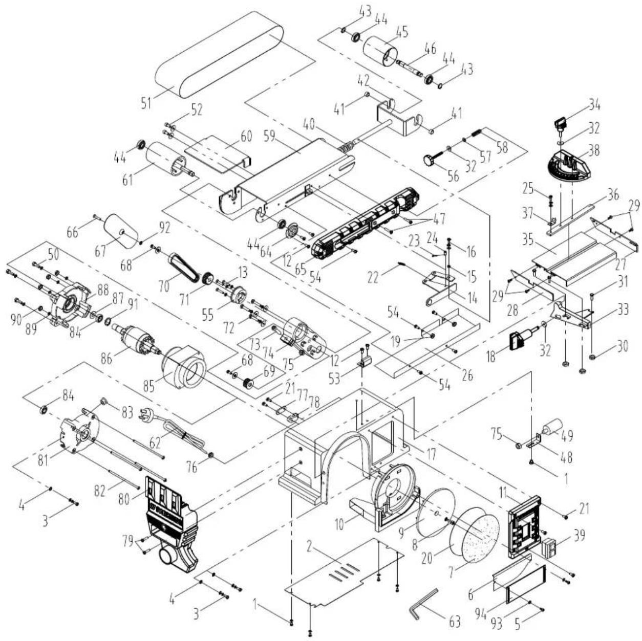
EC Declaration of Conformity
Translation of the original EC declaration of conformity
Article name: BELT & DISC SANDER - PBTS 370 B2
Standard references:
EN 62841-1:2015; EN ISO 12100:2010; EN 55014-1:2017/A11:2020; EN 55014-2:2015; EN 61000-3-2:2014; EN IEC 61000-3-2:2019; EN 61000-3-3:2013; EN 61000-3-3:2013/A1:2019
This declaration of conformity is issued under the sole responsibility of the manufacturer.
Subject to change without notice
Documents registrar: Thomas Schuster
Günzburger Str. 69, D-89335 Ichenhausen
CE
SCHEPPACH GMBH
Günzburg Str. 69
D-89335 Ichenhausen

Last Information Update - Stand der Informationen - Version des informations - Stand van de informatie - Stav informaci - Stan informaci - Stav informaci - Estado de las informaciones - Tilstand af information


- BELT & DISC SANDER - PBTS 370 B2 BAND- UND TELLERSCHLEIFER - PBTS 370 B2 PONCEUSE À BANDE/DISQUE - PBTS 370 B2
- BELT & DISC SANDER
- PONCEUSE A BANDE/DISQUE
- JIENTOB IN DICKOBAIAN
- Table of contents: Page:
- Explanation of the symbols on the device
- Introduction
- Manufacturer:
- Dear customer,
- Note:
- Please consider:
- Device description (fig. 1-19)
- Scope of delivery
- Proper use
- Safety information
- General power tool safety warnings
- Work area safety
- Electrical safety
- Personal safety
- Power tool use and care
- Service
- WARNING!
- Additional safety instructions for the belt and disc sander
- Residual risks
- Technical data
- Wear hearing protection.
- Before commissioning
- Unpacking
- DANGER
- General information
- WARNING
- Attachment and operation
- Assembly (Fig. 1-4b)
- Replacing the grinding belt (Fig. 5-9)
- Adjusting the grinding belt
- Moving the sanding position of the sanding belt (fig. 9-11)
- Replacing the sanding paper on the sanding disc (fig. 12)
- Use as a stationary machine
- Use as a mobile machine
- On/Off switch (5) (Fig. 13)
- Warning:
- Grinding
- Dust extraction connection
- Transport
- Working instructions
- Grinding chamfers and edges (Fig. 14)
- Sanding small end surfaces using the transverse stop (fig. 15a, 15b)
- Horizontal and vertical sanding (fig. 9-11, 16)
- Surface sanding on the sanding belt (fig. 17)
- Grinding concave curves (Fig. 18)
- Grinding convex curves (Fig. 19)
- Cleaning and maintenance
- Warning!
- General maintenance tasks
- General maintenance information
- Cleaning
- Service information
- Available accessories
- Storage
- Electrical connection
- Damaged electrical connection cable
- Safety information for replacing damaged or defective mains connection cables
- Type Y
- AC motor
- Disposal and recycling
- Old devices must not be disposed of with household waste!
- Troubleshooting
- Warranty certificate
- Inhalt:
- Seite:
- Chere CLIENT, Cher Client
- Service-Email (CH):
- Nosite zašcito za sluh.
- Cuprins: Pagina:
- Stimata clienta, stimate client,
- Hotline serviciu (RO):
- Serviciu de e-mail (RO):
- Adresa serviciu (RO):
- Onncanhe Ha ypega (fnr. 1-19)
- O6em Ha doctabkata
- Ynortpe6a no npedHa3haueHne
- YkaaHna 3a 6eOnachOCT
- 06u yka3a 3a 6eonachocst 3a enektpueckn HctpymentH
- 3anaTe BcNk yKa3aHn 3a 6e3oNaCHOCT HnHctpyKuun 3a 6bdeun cnpabKn.
- Be3onachocHT ha pa6oTHOTO MRCTO
- Beonachoc npu pa6ota c enektpnueckn TOK
- Bezonachoct Ha xopata
- Ynortpe6a n 6opabehe c enektpueckna nHcTpymENT
- CepBn3
- PNEyIPEKDEHNEI
- DonbHnTeJHH yKa3aHnra 3a 6esOnacHOCT 3a neHToBata H dNCKOBATA WnHΦOBvHa MaunHa
- △PNEUYPEKDEHNEI
- OctatbHuH pCKObe
- TexHnueckn daHHN
- Hocete 3aunta 3a cnyuxa.
- YKa3AHHe:
- Ппеди nxckaine B ekcnnoatauia
- Pa3onakobae
- ONACHOCT
- O6uynyka3aHn
- PNEUYIPEKJEHNE
- KoHCTpyKunu n 06cnyXbaHe
- Mohtax (pnr. 1-4b)
- CmHa Ha wHnΦobvHata nHTa (fmr.5-9)
- HacpoBaHe Ha wHnΦOBuHata JeHTa
- Perynpahe Ha no3nua Ta Ha unae Hae Ha uhoobuHata neHa (fur. 9-11)
- NocTabaHHe Ha uKypKa BbPxy uNnΦobuHn KpbT (Φnr. 12)
- IVsnonBahe Kato ctaunohapha MaunHa
- IVNONBBAHe KATO MO6MnHa MaunHb
- PpeBknIOuBaTeN 3a BKnIOUbaHe/N3KIOUbaHe (5) (fur.13)
- PpeynpeXdHHe:
- Ⅲafoane
- IVbOa 3a npaxoHcMcykBaHe
- TpaHcnpTupaHe
- 11.Yka3aHnHa 3pa6ota
- Iuaafoane Ha aockn np6oBe (fur. 14)
- Wlaiahe Ha qenHc TpaHn c Hanpeueh orpaHnuHTen (pHr. 15a, 15b)
- XopnsoHTaHNO n BepTHKaIHO wnaJphiHe (pHr.9-11,16)
- NOBbpxHOCTHO WnaiΦaHe Ha WnHΦOBbYHaTa neHTa (fur. 17)
- Wnafoane Ha BnIb6HATn N3BnBKn (pHr. 18) PpeynpeXeHne:
- Wnae Ha n3bKaHn 3BbKn (fur. 19)
- PpeynpexkdeHne:
- NouncTbaHe n noaPbXka
- Ppeynpeckene!
- 06uM Mepkn 3a noapbxxka
- 06uyn yka3aHHa 3a noapbxxka
- NounctBaHe
- CepBmHa MHΦopMaun
- HanuHaKcecoapn
- Cbxpahene
- Enektpuecko Cbbp3Bahe
- Nobpehen Cbbp3BaU eJektpnueckn npoBoaHnk
- Yka3aHn 3a6e3oNaChoc 3a CmHa Ha NOBpeHn Hn DeΦekTHn PpObHnCn 3a CbP3BaHe KbM MpeXata
- Tun Y
- DnraTeH nnpomeHnB TOK
- IVXXBpIaHne IpeuKnnpaHe
- He n3xBpnaTe cTAPnE ypeu B 6ntOBnE orna- dnu!
- OtrtpaHraBaHe Ha Heu3npabHoctn
- 17.「rapanua
- TapaaHNoHHyycnoBna
- Tapannohen cpoK n 3akohOBn npTeHcHn npn deektn
- 06XBaT Ha rapaHnraTa
- Ppoueypa npra npaunnoen cnyuai
- PemOHTeH cepBn3/H3bBhrapaHOnHO 06cnyXBAHe
- CepBn3Ho 06cnyKbaHe
- BbIrapn
- Bhocnten
- PepieXoEva:
- Σελiδa:
- EC Declaration of Conformity
- Standard references:
- EN 62841-1:2015; EN ISO 12100:2010; EN 55014-1:2017/A11:2020; EN 55014-2:2015; EN 61000-3-2:2014; EN IEC 61000-3-2:2019; EN 61000-3-3:2013; EN 61000-3-3:2013/A1:2019
Brand : PARKSIDE
Model : PBTS 370 B2
Category : Sander