
PUG 1600 C3 - Drill PARKSIDE - Free user manual and instructions
Find the device manual for free PUG 1600 C3 PARKSIDE in PDF.
| Product type | Universal machine stand |
| Brand | Parkside |
| Model | PUG 1600 C3 |
| Dimensions (L x W x H) | 1000 - 1650 x 580 x 810 - 910 mm |
| Table height | 750 mm |
| Maximum permissible load capacity | 200 kg |
| Weight | Approx. 13.3 kg |
| Material | Steel |
| Intended use | For mitre saws, scroll saws, table circular saws and other similar power tools |
| Delivery contents | Universal stand, 2 arms, 2 crossbars, 2 workpiece supports, screws, washers, nuts |
| Number of legs | 4 |
| Height adjustment | Yes, via workpiece supports (810 - 910 mm) |
| Support spacing | 1000 - 1650 mm |
| Warranty | 3 years |
| After-sales service France | 0800 904 879 (free) |
| After-sales service Belgium | 0800 71 011 |
| After-sales service Switzerland | 0800 562 153 |
| Care and cleaning | Clean with a damp cloth and mild soap; do not use solvents |
| Safety | Read the safety instructions; do not use as a ladder; max load 200 kg |
| Spare parts | Available during the warranty period |
| Repairability | Repairs by authorized technicians; contact customer service |
Frequently Asked Questions - PUG 1600 C3 PARKSIDE
User questions about PUG 1600 C3 PARKSIDE
0 question about this device. Answer the ones you know or ask your own.
Ask a new question about this device
Download the instructions for your Drill in PDF format for free! Find your manual PUG 1600 C3 - PARKSIDE and take your electronic device back in hand. On this page are published all the documents necessary for the use of your device. PUG 1600 C3 by PARKSIDE.
USER MANUAL PUG 1600 C3 PARKSIDE
213 min 214 min 220 = -2.05 = -
PARKSIDE


UNIVERSAL-MASCHINENUNTERGESTELL / UNIVERSAL TOOL STAND / SUPPORT DE MACHINE UNIVERSEL, PUG 1600 (C)
UNIVERSAL MASCHINENUNTERGESTELL
Inbreng undstieg
Digital: 988.11
(1) 30-36, 37, 50
UNIVERSAL TOOL STAND
Deposition of the poly- and water
[Unreadable]
SUPPORT DE MACHINE UNIVERSEL
Water Data
Treatment of AUSP-100
(10)
UNIVERSAL MACHINEONDERSTEL
(四)
E_1
UNIVERSALNA PODSTAWA POD
M85271
to be in the
Туменника и труда
- 2017年1月1日
PRENOSNY PRACOVNI STUD
Horse's give
单位:
UNIVERSITY PODSTAVEC
Pulley's total valuation
[Unreadable]
.
BASTIDOR INFERIOR UNIVERSAL PARA
MAQUIN
1.2.3.10.16
UNIVERSAL ARBEIDSTATION TIL
MASKINER
(1) (2)
C
①.②.③
CAVALLET
2017年1月1日
②
UNIVERZALIS OEPALLYANT
水のさを示
- let me that place, but
(1)
UNIVERZA
1.2018年1月
(1)
UNIVRETALNI STALOK TA 8157
UNIVERSITY
Proportions
(3)
SUPPORT UNIVERSAL DE SCULE
Phone: (1) 296
2.15.78 min of 30 seconds
2018.10.23
УНИЕРСА
(1) 2017年1月1日
无法识别
(a) (a) (b) (c) Note that the process is called to be a program in the context and we have an external with all functions of the degree.
(2) 10.30
2.12. For commercial and other derivative activities in the 2017–2020 period
4.10.18.20.21.22.23.24.25.26.27.28.29.30.31.32.33.34.35.36.37.38.39.40.41.42.43.44.45.46.47.48.49.50.51.52.53.54.55.56.57.58.59.60.61.62.63.64.65.66.67.68.69.70.71.72.73.74.75.76.77.78.79.80.81.82.83.84.85.86.87.88.89.90.91.92.93.94.95.96.97.98.99.100
- In the case we will take down a day before you to leave
(5) Vcnayy, up, vclanx, zhiyao, zhiyun, mabipu, y, gudh, wainluloyed.
- The company's performance in a setting positive to improve
(2) Pulp (100% of the 30% of the 30% of the 30% of the 30% of the 30% of the 30% of the 30%)
The following table provides the information in the future:
②
公司类型:普通股
(2) 1. _1 (mainly the main line of the main line)
(1) 2023年1月1日
1.20% of the company
- 2017年1月1日
□ No. 1,000
-
Poincentive policy
-
Vonal H. 2017
(2) No. 100000000
(1) _0 (2)
191 2004/10/15
10.2.14
B. Do not know
2017 Unaudet de bilirmei 1 Capex A3
- 2007年1月1日
GUY: Fund.com
(8) NO. 10/19
GAINO@HSCs.BP
2014年
(四) 所有
(2) 10.36
Source: http://www.
2.2报告期末股东总数
IAN 419124_2210
IAN 019124_2210

A
1
2
3
5

DE AT CH
Read and follow the operating and safety instructions before you start working with this power tool!
FR BE CH
- Introduction Page 11
- Device description (fig. 1 - 2) Page 11
- Scope of delivery (fig. 2) Page 11
- Intended use Page 11
- Safety information Page 12
- Technical data Page 12
- Before starting the equipment Page 12
- Attachment and operation Page 12
- Cleaning and storage Page 13
- Transport Page 13
- Disposal and recycling Page 13
- Warranty Page 13
- Service Page 13
UNIVERSAL TOOL STAND
1. Introduction
Manufacturer:
OWIM GmbH & Co. KG
Stiftsbergstraße 1
74167 Neckarsulm
GERMANY
Introduction
We congratulate you on the purchase of your new product. You have chosen a high quality product. Familiarise yourself with the product before using it for the first time. In addition, please carefully refer to the operating instructions and the safety advice below. Only use the product as instructed and only for the indicated field of application. Keep these instructions in a safe place. If you pass the product on to anyone else, please ensure that you also pass on all the documentation with it.
NOTE
According to the applicable product liability laws, the manufacturer of the device does not assume liability for damages to the product or damages caused by the product that occurs due to:
■ Improper handling,
■ Non-compliance of the operating instructions,
■ Repairs by third parties, not by authorized service technicians,
■ Installation and replacement of non-original spare parts,
■ Application other than specified.
Please consider:
Read through the complete text in the operating instructions before installing and commissioning the device.
The operating instructions are intended to help the user to become familiar with the device and take advantage of its application possibilities in accordance with the recommendations.
The operating instructions contain important information on how to operate the device safely, professionally and economically, how to avoid danger, costly repairs, reduce downtimes and how to increase reliability and service life of the machine.
In addition to the safety instructions in these operating instructions and the safety instructions for the machine mounted, you must also observe your country's regulations applicable to the operation of this device and the electric power tool mounted.
Keep the operating instructions package with the device at all times and store it in a plastic cover to protect it from dirt and moisture. Read the instruction manual each time before operating the device and carefully follow its information.
ATTENTION!
The electric power tool mounted on the universal tool stand may only be used by personnel who have been trained in the use of the electric power tool and who have been instructed with respect to the associated hazards. The minimum age requirement must be complied with.
In addition to the safety instructions in this operating manual and the separate regulations of your country, the generally recognised technical rules relating to the operation of such devices must also be observed.
We accept no liability for damage or accidents which arise due to non-observance of these instructions and the safety information.
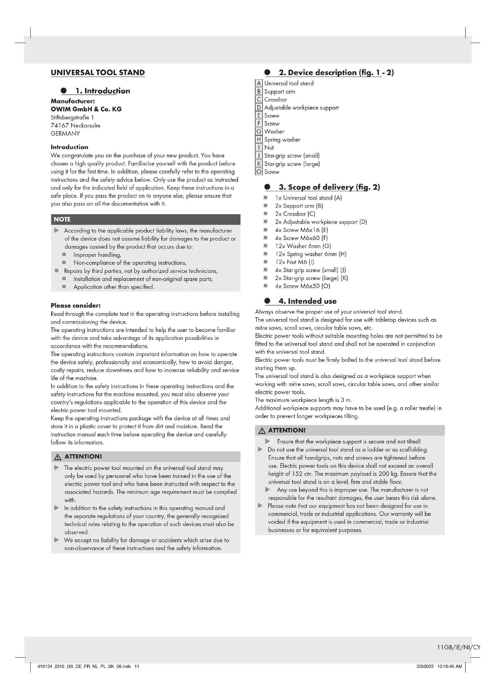
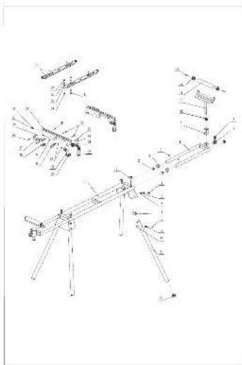
● 2. Device description (fig. 1 - 2)
A Universal tool stand
B Support arm
C Crossbar
D Adjustable workpiece support
E Screw
F Screw
G Washer
H Spring washer
I Nut
J Star-grip screw (small)
K Star-grip screw (large)
○ Screw
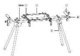
3. Scope of delivery (fig. 2)
1x Universal tool stand (A)
2x Support arm (B)
2x Crossbar (C)
■ 2x Adjustable workpiece support (D)
4x Screw M6x16 (E)
4x Screw M6x60 (F)
12x Washer 6mm (G)
■ 12x Spring washer 6mm (H)
12x Nut M6 (I)
4x Star-grip screw (small) (J)
2x Star-grip screw (large) (K)
4x Screw M6x50 (O)
4. Intended use
Always observe the proper use of your universal tool stand.
The universal tool stand is designed for use with tabletop devices such as mitre saws, scroll saws, circular table saws, etc.
Electric power tools without suitable mounting holes are not permitted to be fitted to the universal tool stand and shall not be operated in conjunction with the universal tool stand.
Electric power tools must be firmly bolted to the universal tool stand before starting them up.
The universal tool stand is also designed as a workpiece support when working with mitre saws, scroll saws, circular table saws, and other similar electric power tools.
The maximum workpiece length is 3 m.
Additional workpiece supports may have to be used (e.g. a roller trestle) in order to prevent longer workpieces tilting.
ATTENTION!
Ensure that the workpiece support is secure and not tilted!
Do not use the universal tool stand as a ladder or as scaffolding. Ensure that all handgrips, nuts and screws are tightened before use. Electric power tools on this device shall not exceed an overall height of 152 cm. The maximum payload is 200 kg. Ensure that the universal tool stand is on a level, firm and stable floor.
Any use beyond this is improper use. The manufacturer is not responsible for the resultant damages, the user bears this risk alone.
Please note that our equipment has not been designed for use in commercial, trade or industrial applications. Our warranty will be voided if the equipment is used in commercial, trade or industrial businesses or for equivalent purposes.
5. Safety information
Use the universal tool stand only in conjunction with suitable electric power tools!
Check the universal tool stand for damage each time before use. Electric power tools shall not be mounted or operated on damaged support arms / crossbars.
Electric power tools must be bolted to the support arms / crossbars and be secured on the universal tool stand!
■ Always ensure the universal tool stand is secure when setting it up.
■ Always ensure that you assume a natural and safe standing position when working.
Do not overload the universal tool stand! Do not use the universal tool stand for purposes for which it is not intended.
To prevent the universal tool stand from tipping over, make sure that the load does not extend laterally beyond the universal tool stand.
■ Modifications or unauthorised changes to the universal tool stand as well as the use of unapproved parts is forbidden.
All parts of the universal tool stand, in particular the safety devices, must be correctly mounted in order to guarantee trouble-free operation.
- Keep the universal tool stand out of reach of children. Store the device in a location that is inaccessible to unauthorised persons and children.
ATTENTION!
When using electric power tools, in conjunction with the universal tool stand, the respective machine-specific safety measures must be implemented as protection against electric shock, and the risk of injury or fire.
Read all of the instructions for the electric power tool that you intend to mount and operate before using the tool.
Safety instructions for the electric device mounted must likewise be observed.
Store these safety instructions safely.
Observe all safety instructions. If you disregard the safety instructions, you endanger yourself and others.
6. Technical data
Dimensions 1000 - 1650 x 580 x 810 - 910 mm
Table height 750 mm
Height of the side expansions 810 - 910 mm
Spacing of the supports min./max 1000 - 1650 mm
Max. permissible payload 200 kg
Weight approx. 13.3 kg
● 7. Before starting the equipment
Check the device for transport damage. Immediately report any damage to the transport company that delivered the device.
■ Open the packaging and remove the device carefully.
■ Remove the packaging material as well as the packaging and transport bracing (if available).
- Check that the delivery is complete.
- Check the device and accessory parts for transport damage.
If possible, store the packaging until the warranty period has expired.
ATTENTION!
The device and packaging materials are not toys! Children must not be allowed to play with plastic bags, film and small parts! There is a risk of swallowing and suffocation!
● 8. Attachment and operation
The universal tool stand is largely assembled and you need only fit the handgrips and the workpiece supports as follows:
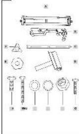
8.1 Erecting the universal tool stand (fig. 3 - 4)
Place the universal tool stand (A) on the floor or on a workbench such that the frame legs (A.1) point upwards.
Press the spring pin (M) and fold out the frame leg.
Once the spring pin (M) latches into the intended position (L), the frame leg is locked.
Repeat this process for the other frame legs.
Set the universal tool stand down on its feet.
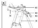
8.2 Mounting support arms (fig. 5)
Fit the support arms (B) to the frame bed (A) by pulling the locking lever (B.3) upwards to unlock it and then latching the arm into place on the frame base, firstly on the front side (B.2).
Lower the rear side onto the bed and fasten the support arm in place on the frame bed by pressing the locking lever (B.3).
Disassembly is carried out in reverse order.
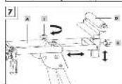
8.3 Fitting the workpiece supports (fig. 6 - 7)
Insert the workpiece support (D) into the receiver (N) of the frame bed and fasten in place with the star-grip screws (K).
The width and height of the workpiece supports can be adjusted with the star-grip screws (J, K). (fig. 7)
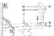
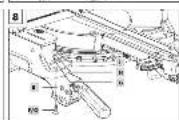
8.4 Fastening your tabletop machine (fig. 8)
Different tabletop machines can be fastened to your universal tool stand by adjusting the support arms (B) to the spacing of the mounting holes on your machine.
Place your tabletop machine (e.g. mitre saw) on the support arms (B).
■ Fasten the tabletop machine with 4 hexagonal screws (F/O), 4 washers (G), 4 spring washers (H) and 4 hexagonal nuts (I) on each of the support arms.
■ Tighten the screws after assembly.
- Fasten the support arms (B) with the mounted tabletop machine on the universal tool stand, as described in point 8.2.
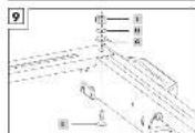
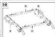
If your machine has different hole spacing for mounting, use the crossbars (C) provided as an adapter. (fig. 9-11)
Connect the crossbars (C) with the support arms (B) and secure them with 4 hexagonal screws (E), 4 washers (G), 4 spring washers (H) and 4 hexagonal nuts (I).
- Place your tabletop machine on the crossbars (C).
■ Fasten the tabletop machine with 4 hexagonal screws (F/O), 4 washers (G), 4 spring washers (H) and 4 hexagonal nuts (I) on each of the crossbars (C).
■ Tighten the screws after assembly.
■ Fasten the support arms with the mounted tabletop machine on the universal tool stand, as described in point 8.2.
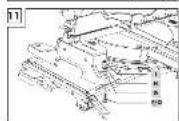
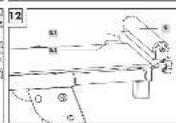
8.5 Using the workpiece stops (fig. 12)
The workpiece supports (D) have integrated workpiece stops (D.2), which can be used to saw multiple pieces of wood to the same length.
- Loosen the star-grip screw (K) on the desired side of the universal tool stand and adjust the height of the workpiece support (D) such that the support surface (D.2) is at the same height as the workpiece support of the saw.
- Loosen the star-grip screw (J) to slide the workpiece support horizontally.
- Set the desired distance between the saw blade and the stop surface (D.1).
■ Lock your setting by tightening the star-grip screws (J) again.
● 9. Cleaning and storage
IMPORTANT!
Before any cleaning or maintenance work, the electrical tool fitted must be switched off and the mains plug pulled out! Risk of injury!
9.1 Cleaning
- Keep the universal tool stand as free of dust and dirt as possible. Rub the universal tool stand clean with a clean cloth or blow it off with compressed air at low pressure.
We recommend that you clean the universal tool stand immediately after every use. - Clean the device at regular intervals using a damp cloth and a little soft soap. Do not use any cleaning products or solvents - they could attack the plastic parts of the universal tool stand.
9.2 Storage
ATTENTION!
Store the universal tool stand only in dry locations that are inaccessible for unauthorised persons.
10. Transport
ATTENTION!
Do not transport whilst the electric power tool is running.
Before transporting the universal tool stand, pull out the mains plug of the electric power tool mounted on it! Risk of injury due to electric shock and unexpected start-up of the electric power tool!
▶ Two people can lift the universal tool stand by its frame bed in order to move the universal tool stand within rooms (do not drag it along the ground).
If being transported in a vehicle, remove the electric power tool first. Fold up the legs for transport.
▶ Ensure that the load is well secured if transporting the universal tool stand in a motor vehicle.
● 11. Disposal and recycling
The packaging is made entirely of recyclable materials, which you may dispose of at local recycling facilities.
Contact your local refuse disposal authority for more details of how to dispose of your worn-out product.
Product:

The product incl. accessories and packaging materials are recyclable and are subject to extended producer responsibility.
Dispose them separately, following the illustrated Info-tri (sorting information), for better waste treatment.
The Triman logo is valid in France only.
12. Warranty
The product has been manufactured to strict quality guidelines and meticulously examined before delivery. In the event of product defects you have legal rights against the retailer of this product. Your legal rights are not limited in any way by our warranty detailed below.
The warranty for this product is 3 years from the date of purchase. The warranty period begins on the date of purchase. Please keep the original sales receipt in a safe location. This document is required as your proof of purchase.
Should this product show any fault in materials or manufacture within 3 years from the date of purchase, we will repair or replace it - at our choice - free of charge to you. This warranty becomes void if the product has been damaged, or used or maintained improperly.
The warranty applies to defects in material or manufacture. This warranty does not cover product parts subject to normal wear, thus possibly considered consumables (e.g. batteries) or for damage to fragile parts, e.g. switches, rechargeable batteries or glass parts.
Warranty claim procedure
To ensure quick processing of your case, please observe the following instructions:
Please have the till receipt and the item number (IAN 419124_2210) available as proof of purchase.
You will find the item number on the rating plate, an engraving on the front page of the instructions for use (bottom left), or as a sticker on the rear or bottom of the product.
If functional or other defects occur, please contact the service department listed either by telephone or by e-mail.
You can return a defective product to us free of charge to the service address that will be provided to you. Ensure that you enclose the proof of purchase (till receipt) and information about what the defect is and when it occurred.
13. Service
GB Service Great Britain
Tel.:08000569216
E-Mail:owim@lidl.co.uk
IE Service Ireland
Tel.:1800200736
E-Mail:owim@lidl.ie
Ni Service Northern Ireland
Tel.:08000927852
E-Mail:owim@lidl.ie
MT Service Malta
Tel.:80062960
E-Mail:owim@lidl.com.mt
CY Service Cyprus
Tel.:80094211
E-Mail:owim@lidl.com.cy

At www.lidl-service.com you can download this and many more manuals, product videos plus installation software.
The QR code takes you directly to the Lidl service page (www.lidl-service.
com) and you can open your operating manual by entering the article number (IAN) 419124_2210.
Weight Pribl. 13,3 kg
7. Pred zagonom orodja
Preverite, ali se je naprava morda poškodovala med transportom.
Morebitno transportno škodo nemudoma prijavite podjetju, ki je dobavilo napravo.
- Odprite embalažo in previdno odstranite napravo.
- Odstranite embalažo in morebitne opore.
Zagotovite, da so dobavljeni vse komponente.
■ Preverite, ali je med transportom prišlo do poškodb naprave in pripomočkov.
Če imate možnost, shranite embalažo do poteka garancije.
POZOR!
Pooblaščeni serviser:
OWIM GmbH & Co. KG
Stiftsbergstraße 1
74167 Neckarsulm
NEMČIJA


- PARKSIDE
- UNIVERSAL TOOL STAND
- Introduction
- Manufacturer:
- OWIM GmbH & Co. KG
- Introduction
- NOTE
- Please consider:
- ATTENTION!
- ● 2. Device description (fig. 1 - 2)
- Scope of delivery (fig. 2)
- Intended use
- Safety information
- Store these safety instructions safely.
- Technical data
- ● 7. Before starting the equipment
- ● 8. Attachment and operation
- Erecting the universal tool stand (fig. 3 - 4)
- Mounting support arms (fig. 5)
- Fitting the workpiece supports (fig. 6 - 7)
- Fastening your tabletop machine (fig. 8)
- Using the workpiece stops (fig. 12)
- ● 9. Cleaning and storage
- IMPORTANT!
- Cleaning
- Storage
- Transport
- ● 11. Disposal and recycling
- Product:
- Warranty
- Warranty claim procedure
- Service
- Pred zagonom orodja
- POZOR!
- Pooblaščeni serviser:
Brand : PARKSIDE
Model : PUG 1600 C3
Category : Drill