
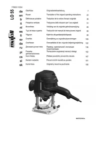
LS 103 Ec - Milling machine Mafell - Free user manual and instructions
Find the device manual for free LS 103 Ec Mafell in PDF.

| Product type | Chain mortiser (chain slot mortiser) |
| Brand | Mafell |
| Model | LS 103 Ec |
| Service voltage | 230 V AC / 120 V AC |
| Mains frequency | 50 Hz / 60 Hz |
| Continuous power consumption | 2500 W |
| Continuous current consumption | 13 A (230 V) / 20 A (120 V) |
| No-load speed | 4050 min⁻¹ (230 V) / 4400 min⁻¹ (120 V) |
| Mortising depth | 100 mm (without FG 150 support); 150 mm (with FG 150 support) |
| Weight (machine only) | 8.7 kg |
| Weight of guide support FG 150 | 4.6 kg |
| Sound pressure level | 100 dB(A) |
| Sound power level | 108 dB(A) |
| Hand-arm vibration | 5.1 m/s² |
| Protection class | II |
| Standard equipment | Guide rail, mortising chain, sprocket, transverse stop, mortising tools, instruction manual |
| Intended use | Mortising of solid wood with mortising chains |
| Safety instructions | Wear hearing protection, mask and goggles; disconnect before maintenance; do not work without chain guard |
| Chain maintenance | Clean and lubricate every 2 hours of work in a thin oil bath |
| Lubrication | Use special MAFELL grease part no. 049040 |
| Storage | Clean thoroughly and spray metal parts with a rust inhibitor |
| Available accessories | Guide support FG 150, notching devices SG 230/400/500, guides and replacement chains |
Frequently Asked Questions - LS 103 Ec Mafell
User questions about LS 103 Ec Mafell
0 question about this device. Answer the ones you know or ask your own.
Ask a new question about this device
Download the instructions for your Milling machine in PDF format for free! Find your manual LS 103 Ec - Mafell and take your electronic device back in hand. On this page are published all the documents necessary for the use of your device. LS 103 Ec by Mafell.
USER MANUAL LS 103 Ec Mafell
Please read all safety instructions and directions. Failure to comply with the safety instructions and directions can cause electric shock, fire and/or serious injuries. Please retain all safety instructions and directions for future reference.
AVERTISSEMENT
GB - EC Declaration of Conformity
We herewith confirm that the machine LS 103 Ec complies with the EU directives quoted. The standards listed were used for design and construction. Empowered person for the configuration of the technical documents: Mafell AG
924220, 924221, 924228, 924229, 924240, 924260,
924262, 924263
Mafell AG
Beffendorfer Str. 4
1 Signs and symbols 15
2 Product information 15
2.1 Manufacturer's data 15
2.2 Machine identification 15
2.3 Technical data 16
2.4 Emissions 16
2.5 Scope of supply 16
2.6 Use according to intended purpose 17
2.7 Residual risks 17
3 Safety instructions 17
4 Setting/Adjustment 18
4.1 Mains connection 18
4.2 Installation mortising chain set 18
4.3 Mortising chain change 18
4.4 Chain wheel change 19
5 Operation 19
5.1 Initial operation 19
5.2 Switching on and off 19
5.3 Cross fence setting 19
5.4 Mortising depth adjustment 20
5.5 Operating method 20
5.6 Mortising recesses 20
6 Service and maintenance 20
6.1 Mortising chains 20
6.2 Storage 20
7 Troubleshooting 20
8 Optional accessories 21
9 Exploded drawing and spare parts list 21
1 Signs and symbols

This symbol is found in all places where you will find information for your safety.
Non-compliance with these instructions may result in very serious injuries.

This symbol indicates a potentially hazardous situation.
If this situation is not avoided, the product or objects in its vicinity may get damaged.

This symbol indicates tips for the user and other useful information.
2 Product information
for machines with product no. 924201, 924202, 924203, 924204, 924205, 924206, 924220, 924221, 924228, 924260, 924262, 924263
2.1 Manufacturer's data
MAFELL AG, Beffendorfer Straße 4, D-78727 Oberndorf / Neckar, Phone +49 (0)7423/812-0, Fax +49 (0)7423/812-218, e-mail: mafell@mafell.de
2.2 Machine identification
All details required for machine identification are available on the attached rating plate.

Protection class II

CE symbol to document compliance with the basic safety and health requirements according to Appendix I of the Machinery Directive.

For EU countries only
Do not dispose of electric tools together with household waste material!
In accordance with the European directive 2002/96/EC on waste electrical and electronic equipment and transposition into national law, obsolete electrical tools must be collected separately and recycled in an environmentally-compatible manner.

To reduce the risk of injury, please read the operating instructions.
2.3 Technical data
| Operating voltage | 230 V AC | 120 V AC |
| Mains frequency | 50 Hz | 60 Hz |
| Input power continuous operation | 2500 W | |
| Power consumption continuous operation | 13 A | 20 A |
| Speed during idling | 4050 rpm | 4400 rpm |
| Mortising depth | 100 mm (3 15/16 in.) | |
| Mortising depth with guide support stand FG 150, order No. 200 | 150 mm (5 7/8 in.) | |
| 980 | ||
| Weight without mains cable LS 103 Ec | 8.7 kg (19.18 lbs) | |
| Weight guide support stand FG 150, order No. 200 980 | 4.6 kg (10.1 lbs) | |
2.4 Emissions
The declared noise emission values have been measured in accordance with EN 62841-1 and may be used for comparing the tool with another and also in a preliminary assessment of exposure.

Danger
The noise emissions during actual use of the power tool can differ from the declared values depending on the ways in which the tool is used especially what kind of workpiece is processed.
Always wear hearing protection, even when the power tool ist running idle in addition to the trigger time!
2.4.1 Noise emission specifications
Noise emission values determined according to EN 62841:
Sound pressure level L_PA = 100dB(A)
Uncertainty K PA = 1,5dB (A)
Sound power level L WA=108 dB (A)
Uncertainty K_WA = 1,5dB(A)
2.4.2 Vibration specifications
The typical hand-arm vibration is 5.1m / s^2
2.5 Scope of supply
Single-phase chain mortiser LS 103 Ec complete with:
1 guide rail, cpl.
1 mortising chain
1 chain wheel
1 crossfeed stop
2 operating tools
1 operating manual
1 folder "Safety Instructions"
2.6 Use according to intended purpose
The single-phase chain mortiser is exclusively intended for mortising solid wood using mortising chains. The dimensions of the mortising chain sets used (guide rail, mortising chain and chain wheel) must correspond to the mortising chain sets listed in the operating instructions.
Any other use than described above is not permissible. The manufacturer cannot be held liable for any damage arising from such other use.
So as to use the machine as intended, comply with the operating, maintenance and repair instructions specified by Mafell.
2.7 Residual risks

Danger
Even if used in accordance with its intended purpose and despite conforming with the safety instructions, residual risks caused by the intended use that can lead to health consequences will always remain.
- Touching the mortising chain in the exposed area.
- Touching the part of the mortising chain that protrudes below the workpiece when mortising.
- Touching the mortising chain from the side.
- Tearing of the mortising chain.
- Backlash of the machine against the operator if the cross fence is not fastened during freehand milling.
- Touching live parts with the housing open and the mains plug not removed.
- Hearing can be impaired when working for long periods without ear protectors.
- Emission of harmful wood dusts during longer operation without extraction.
3 Safety instructions

Danger
Always observe the following safety instructions and the safety regulations applicable in the respective country of use! Please also read the safety information in the enclosed folder 070500 "Safety instructions" (according to standard 62841-1).
General instructions:
- Children and adolescents must not operate this machine. This rule does not apply to young persons receiving training and being supervised by an expert.
- Never work without the protection devices prescribed for the respective operating sequence and do not make any changes to the machine that could impair safety.
- When operating the machine outdoors, use of an earth-leakage circuit-breaker is recommended.
- Damaged cables or plugs must be immediately replaced. Replacement may only be carried out by Mafell or an authorised MAFELL service workshop in order to avoid safety hazards.
- Avoid sharp bends in the cable. Especially when transporting and storing the machine, do not wind the cable around the machine.
Instructions on the use of personal protective equipment:
- Always wear ear protectors during work.
- Always where a dust mark during work.
- Always wear protective goggles during work.
Instructions on operation:
- Provide for an unobstructed and slip-proof location with sufficient lighting.
- The power plug must be pulled before replacing tools, making adjustments and repairing malfunctions (this also comprises removing jammed splinters).
-
Do not work on workpieces which are too small or too large for the capability of the machine.
-
Clamp the mortising chain and the guide rail properly and keep it in good repair. Before reusing them, repair defective mortising chains professionally and only use sharp mortising chains!
- Caution: For machines without guide support stand FG 150, use solely 100mm (3 5/16 inch) mortising chain sets!
- Remove the chain guard only for a tool change and screw it back on again immediately afterwards. Never work without chain guard!
- Never transport the chain mortiser with running mortising chain and avoid touching the ground with the running mortising chain!
- The switch may not be wedged.
- Before switching on the mortising chain, check whether it is properly tensioned.
- Whenever possible secure the workpiece from pivoting or sliding away, overturning and luffing up, e.g by means of clamps.
- Only begin mortising the workpiece when the mortising chain has achieved its full speed.
- Examine the workpiece for foreign objects. Never attempt to stem into metal objects, such as nails.
- Keep a firm hold on the machine already before switching it on. The mortising chain must stand unobstructed while doing so. Apply the machine for the mortising operation with running mortising chain. Pay attention to a secure footing.
- Always lead the connecting cable away from the machine to the rear while mortising.
- Match the feed speed during mortising to the material thickness. Mortising too quickly leads to motor overload, to unclean mortises and to the mortising chain blunting quickly.
- Only remove the machine from the workpiece if it has come to a standstill.
- Do not reach into the chip ejector and the unprotected area of the mortising chain while the machine is running.
- Before switching on the machine for freehand milling, pay attention that the cross fence is fastened and rests against the workpiece. Milling must not start without cross fence!
- Only use the machine outdoors or in well ventilated rooms.
- Wear a dust mask during machine operation.
Instructions on service and maintenance:
- Regularly cleaning the machine, especially the adjusting devices and guides, constitutes an important safety factor.
- Only original MAFELL spare parts and accessories may be used. Otherwise the manufacturer will not accept any warranty claims and cannot be held liable.
- Wear protective gloves for all maintenance and repair work.
4 Setting / Adjustment
4.1 Mains connection
Prior to commissioning make sure that the mains voltage complies with the operating voltage stated on the machine's rating plate.
4.2 Installation mortising chain set

Danger
Pull the power plug during all service work.
- Lightly screw on the guide rail with the cylinder head bolt. Pay attention that the guide rail rests planely in the guide on the gearbox case and possibly unscrew the threaded pin 14 (Fig. 1).
- The installation of mortising chain and chain wheel is carried out as described under 4.3 and 4.4.
4.3 Mortising chain change

Danger!
Pull the power plug during all service work.
Pay attention that the mortising chain to be clamped has been well sharpened as this is the basic requirement for correct mortising.
Proceed as follows to replace the mortising chain:
- First slacken the mortising chain by means of the threaded pin 14 (Fig. 1).
- Remove the chain guard 11 (Fig. 2) by simultaneously unfastening the two knurled screws.
- Unfasten the cylinder head bolt 16.
-
Unfasten and remove the countersunk bolt in the transmission shaft.
-
Remove the chain wheel, mortising chain and guide rail together.
- For installation, proceed in reverse order.
- Refit the new mortising chain together with the chain wheel and the guide rail and pay attention that the cutting teeth are running in working direction (see arrow on the chain guard 11 (Fig. 2)).
- Fasten the countersunk bolt in the transmission shaft.
- Lightly tighten the cylinder head bolt 16 and clamp the mortising chain with the threaded pin 14 (Fig. 1). The correct chain tension has been achieved if the mortising chain can be lifted approx. 6mm (1/4 in.) in the middle of the guide rail.
- Securely retighten the cylinder head bolt 16 (Fig. 2) after completion of the adjustment work.
- Refit the chain guard 11!
4.4 Chain wheel change

Danger
Pull the power plug during all service work.
- During a chain wheel change, the countersunk screw in the gear shaft must be unscrewed with the Allen key fastened on the machine by knocking lightly against the key.
- For installation, proceed in reverse order. Push the new chain wheel onto the gear shaft such that the chain wheel groove gears into the straight pin, which is pushed crossways through the gear shaft.
5 Operation
5.1 Initial operation
Personnel entrusted to work with the machine must be made aware of the operating instructions, calling particular attention to the chapter "Safety instructions".
5.2 Switching on and off

Danger
Pay attention that the mortising chain can be moved freely.
Lead the connecting cable away to the rear.
Hold onto the machine with both hands.
Only switch on the machine if the mortising chain has no contact with the workpiece.
- Switching on: First unlock the switch-on lock to the front by pressing the locking lever 4 (Fig. 2). Then actuate the control lever 3. As this is a switch without locking device, the machine will only run for as long as this switch is pressed.
- Switching off: Release control lever 3. The switch-on lock automatically takes effect again and secures the machine against accidental switch-on.

Switch-on procedures create a temporary reduction in voltage. In case of unfavourable grid conditions, this may lead to the impairment of other devices.
In case of grid impedances smaller than 0.27 Ohm, no interferences are to be expected.
5.3 Cross fence setting
The distance between mortise and collar side is stepplessly variable from 8 to 150mm (5/16 to 5 7/8 in.) with the crossfeed stop 6 (Fig. 2).
- Release the clamping lever 8 and set the distance on scale 7. Note the reading edge depending on the hole width 30, 35 or 40mm (1 3/16, 1 3/8 or 1 9/16 in.)!
- Securely retighten the clamping lever 8 afterwards. The clamping lever is adjustable and can be brought into any desired clamping position by lifting it.
5.4 Mortising depth adjustment
The mortise depth is continuously variable.
- Release clamping lever 10 (Fig. 2) and set the depth stop 9 to depth using a yard stick.
- Tighten clamping lever 10 (adjustable as 8) - do not place in mortising direction! The mortising depth depends on the mortising chain set used.
5.5 Operating method
To start mortising, hold the machine by its two handles 1 and 2 (Fig. 2) and guide it - the crossfeed stop 6 must rest against the wood. First mortise the start and end of the mortise and then the rest. Mortise with even pressure and infeed. The mortising chain should be cleaned and lubricated in a low viscosity oil bath after two hours of operation.
5.6 Mortising recesses
For this, two wooden ledges can be screwed on at the drill holes 4.5mm (11/64 in.) on the crossfeed stop 6 (Fig.2) (see Fig.4).
6 Service and maintenance

Danger
Pull the power plug during all service work.
MAFELL machines are designed to be low in maintenance.
The ball bearings used are greased for life. When the machine has been in operation for a longer period of time, we recommend to hand the machine in at an authorised MAFELL customer service shop for inspection.
Only use our special grease, order No. 049040 (1 kg tin) for all greasing points.
6.1 Mortising chains
The mortising chain used on the machine should be cleaned and lubricated in a low viscosity oil bath after two hours of operation. To do so, dismantle the mortising chain (see chapter 4.3).
Replace the blunt mortising chains or have them reground at a MAFELL customer service station or by a suitable sharpening service.
6.2 Storage
Clean the machine thoroughly if the machine is not used for a longer period of time. Spray blank metal parts with a rust-proofing agent.
7 Troubleshooting

Danger
Determining the causes for existing defects and eliminating these always requires increased attention and caution. Pull the mains plug beforehand!
Some of the most frequent defects and their causes are listed in the following chart. In case of other defects, please contact your dealer or the MAFELL customer service directly.
| Defect | Cause | Elimination |
| Machine cannot be switched on | No mains voltage | Check power supply |
| Carbon brushes worn | Take the machine to a MAFELL customer service shop | |
| Chip ejection blocked | Wood is too damp | Clean chip ejection |
| Machine stops while cutting is in process | Mains failure | Check mains back-up fuses |
| Machine overloaded Reduce feed speed | ||
| Carbon brushes worn | Take the machine to a MAFELL customer service shop | |
8 Optional accessories
- Guide support stand FG 150 Order No. 200980
- Slot mortising device SG 230 Order No. 200990
- Slot mortising device SG 400 Order No. 201000
- Slot mortising device SG 500 Order No. 201005
- Clamping device (for SG 400) Order No. 039602
- Guide rail, cpl. 28x40x100 Order No. 091010
- Guide rail, cpl. 28x40x150 Order No. 091011
- Guide rail, cpl. 28x30/35x100 Order No. 091012
- Guide rail, cpl. 28x30/35x150 Order No. 091013
- Guide rail, cpl. 30x30/35x100 Order No. 091014
- Guide rail, cpl. 28x1.5x150 Order No. 091016
- Guide rail, cpl. 28x2x150 Order No. 091017
- Mortising chain 28x35/40/50x100 Order No. 091224
- Mortising chain 28x35/40x100 Order No. 091230
- Mortising chain 28x35/40x150 Order No. 091234
- Spare links with rivets 28 mm Order No. 091279
-Chain wheel 28x35/40 Order No.091683
9 Exploded drawing and spare parts list
The corresponding information in respect of spare parts can be found on our homepage: www.mafell.com
Notes for after-sales service:
If a LS 103 Ec (with Cuprex motor) is to be mounted on an existing slot mortising device SG 400 or SG 500 at the customer's (up to year of manufacture 2006), the pinion cpl. (pos. 2), item No 200842 on the slot mortising device must be replaced by pinion cpl. 204740.
The handle on the pinion cpl. 204740 can be detached by means of the Allen key SW 4 which is included as accessory with the LS 103 Ec and used to attach the LS 103 Ec on the SG 400 / SG 500.
Sommaire
pour les machines portant le n d'art. 924201, 924202, 924203, 924204, 924205, 924206, 924220, 924221, 924228, 924260, 924262, 924263
bij machines met art.-nr. 924201, 924202, 924203, 924204, 924205, 924206, 924220, 924221, 924228, 924260, 924262, 924263
Koneille, joilla on tuote-nro: 924201, 924202, 924203, 924204, 924205, 924206, 924220, 924221, 924228, 924260, 924262, 924263
for maskiner med articelnummer 924201, 924202, 924203, 924204, 924205, 924206, 924220, 924221, 924228, 924260, 924262, 924263
K Maunam capT. No 924201, 924202, 924203, 924204, 924205, 924206, 924220, 924221, 924228, 924260, 924262, 924263
2.1 CBeHeHnO npOn3BODnte
MAFELL AG, Beffendorfer Straße 4, D-78727 Oberndorf / Neckar, Teilepoh +49 (0)7423/812-0, øakc +49 (0)7423/812-218, øl. nouTa mafell@mafell.de
2.2 MapKIpOBKa MaunHbI
Bce daHHbe, Heo6xoDnMbIe IINIeHTnФuKaIIM MaunHbI, yKa3aHbI Ha 3aBOJcKo Ta6JIuYe.

Knacc 3aunTbI II

Cnmbon CE nnoTBepeXdeHncooTBeCTBnO OCHOBbIM Tpe6OBaHnM 6e3oNaChocn u 3dpabooxpaHeHn, cornacho npuIooKeHIO I K DnpeKtNBe o MaunHax
TolbokdЯ cTpaH EC
He 6pocaiTe 3JIeKTpOuHcTpyMeHTbI B 6bITOBoM mycop!
Cornacno Ebponecko dnpekTbe 2002/96/EG o6 ycTapeBwix 3neKtpuecknx n 3neKTPOHbIX npnbopax n aHaIOnuHbIM 3aKohAm OTdeJIbHbIX CTpaH, IcNoJIb3OBAHHbIE 3neKTPoIHCTpyMeHTbl DOJXHbI CObipaTBcR OTdeJIbHO INpePaBaTbcr drr daIbHeIwero nCpONb3OBaHn8 be3 yUep6a drr OkpykaIOse Cpebl.

IpoHTaTe INHCTpyKcNIO NO 3KcPnyatauIN DnY yMeHbSeHnO nAcHOCTn noJyHeHn TpaBM.
2.3 TexHnueckne xapaKTepeNCTNKN
| Равоче наразожения | 230 B peperm. | 120 B peperm. |
| TOKA | TOKA | |
| Частota сети | 50 Г. | 60 Г. |
| ПOTравлиемая мошноctь (рп-рд-л-к-п-м-п-х-у-м-р-х-у-х-п-х-п-х-п-х-п-х-п-х-п-х-п-х-п-х-п-х-п-х-п-х-п-х-п-х-п-х-п-х-п-х-п-х-п-х-п-х-п-х-п-х-п-х-п-х-п-х-п-х-н-п-х-п-х-п-х-п-х-п-х-п-х-п-х-п-х-п-х-п-х-п-х-п-х-п-х-п-х-п-х-п-х-п-х-п-х-п-х-п-х-п-х-п-х-п-х-п-х-п-x-x-x-x-x-x-x-x-x-x-x-x-x-x-x-x-x-x-x-x-x-x-x-x-x-x-x-x-x-x-x-x-x-x-x-x-x-x-x-x-x-x-x-x-x-x-x-x-x-x-x-x-x-x-x-x-x-x-x-x-x-x-x-x-x-x-x-x-x-x-x-x-x-x-x-x-x-x-x-x-x-x-x-x-x-x-x-x-x-x-x-x-x-x-x-x-x-x-x-x-X-x-x-x-x-x-x-x-x-x-x-x-x-x-x-x-x-x-x-x-x-x-x-x-x-x-x-x-x-x-x-x-x-x-x-x-x-x-x-x-x-x-x-x-x-x-x-x-x-x-r | 2500 BT | |
| ПOTравлиемая мошноctь (рп-рд-л-н-м-х-m-р-m-x-m-x-x-x-x-x-x-x-x-x-x-x-x-x-x-x-x-x-x-x-x-x-x-x-x-x-x-x-x-x-x-x-x-x-x-x-x-x-x-x-x-x-x-x-x-x-x-x-x-x-nr | 13 A | 20 A |
| ПOTравлиемя (л-л-н-m-p-m-q-np-nq-np-nq-np-nq-np-nq-np-nq-np-nq-np-nq-np-nq-np-nq-np-nq-np-nq-np-nq-np-nq-n | 4050 MHN-1 | 4400 MHN-1 |
| Глухиа (л-л-н-m-p-m-q-np-nq-np-nq-np-nq-np-nq-np-nq-np-nq-np-nq-np-nq-np-nq-np-nq-np-nq-np-nq-np-nq-np-nq-np-nq-np-nq-np-nq-np-nq-np-nq-np-nq-np-nq-np-nq-np-nq-nq-np-nq-np-nq-np-nq-np-nq-np-nq-np-nq-np-nq-np-nq-np-nq-np-nq-np-nq-np-n q | 100 MM | |
| Звес\text{сe}\text{e}\text{b}\text{o}\text{u}\text{e}\text{a}\text{e}\text{u}\text{e}\text{a}\text{e}\text{u}\text{e}\text{a}\text{e}\text{u}\text{e}\text{a}\text{e}\text{u}\text{e}\text{a}\text{e}\text{u}\text{e}\text{a}\text{a}\text{e}\text{u}\text{e}\text{a}\text{e}\text{u}\text{e}\text{a}\text{e}\text{u}\text{e}\text{a}\text{e}\text{u}\text{e}\text{a}\text{e}\text{u}\text{a}\text{e}\text{u}\text{e}\text{a}\text{e}\text{u}\text{e}\text{a}\text{e}\text{u}\text{e}\text{a}\text{e}\text{u}\text{e}\text{a}\text{e}\text{u}\text{c}\text{e}\text{e}\text{u}\text{e}\text{u}\text{e}\text{u}\text{e}\text{u}\text{e}\text{u}\text{e}\text{u}\text{e}\text{u}\text{e}\text{u}\text{e}\text{u}\text{e}\text{u}\text{e}\text{a}\text{a}\text{a}\text{a}\text{a}\text{a}\text{a}\text{a}\text{a}\text{a}\text{a}\text{a}\text{a}\text{a}\text{a}\text{a}\text{a}\text{a}\text{a}\text{a}\text{u}\text{u}\text{u}\text{u}\text{u}\text{u}\text{u}\text{u}\text{u}\text{u}\text{u}\text{u}\text{u}\text{u}\text{u}\text{u}\text{u}\text{u}\text{u}\text{u}\text{a}\text{a}\text{a}\text{a}\text{a}\text{a}\text{a}\text{a}\text{a}\text{a}\text{a}\text{a}\text{a}\text{a}\text{a}\text{a}\text{a}\text{a}\text{a}\text{grrrrrrrrrrrrrrrrrrrrrrrrrrrrrrrrrr Bec б e e e e e e e e e e e e e e e e e e e e a a a a a a a a a a a a a a a a a a e e e e e e e e e e e e e e e e e e e r r r r r r r r r r r r r r r r r r r r r r r r r r r r r r r r $r |
2.4 Bbipoc
Yka3aHHbIe ypOBHn 7yMa 6blnn N3MepeHb I B COOTBETCTBm CO cTaHdapTOM EN 62841-1 n Moryr NCNoJIb3OBAtbcra dIg CpaBHeHna 3IeKTPoIHcTpymeHTa C dpYrIM IHcTpymeHTOM n dIg PpeDbapntelHOJ OueHKn Harpy3Kn.

Onacho
При ИСПОЛБЗОВАнМ 3ЛЕКТРОИСТPyмЕТа урOBи шуMa MOryT OTПИЧАСЯOT yka3aHHbIX 3нauЧeн. 3TO 3aBиСТ OT спOCба ИСПОЛБЗОВАнИНСТPyмЕТа, BчacTHOCTи, OT TИNA OБразыBaEMоДтАПИ.
IooTOMy Bcerda nCnoJb3yIte cpeIcTBa 3aunIbI opraHOB clyxa, daXe KOrda 3neKtpoHHCTpyMeHT pa6OtaET 6e3 harpy3kn!
2.4.1 DaaHbIe no n3JyueHnO wyma
3haenraaHyaMa, nmepeHHbIe, cornacho EN 62841, coctabnT:
ypoBHeH 3BykoBOrO daBneHnRA L PA=100dA(B(A)
norpewnoctbK PA=1,5D5(A)
ypoBHeHb 3ByKOBoM OuHocTn LwA = 108 d5 (A)
norpeuhoctb KwA=1,5D(A)
do maszyn z nr art. 924201, 924202, 924203, 924204, 924205, 924206, 924220, 924221, 924228, 924260, 924262, 924263
2.1 Dane dot.producenta
MAFELL AG, Beffendorfer Straße 4, D-78727 Oberndorf / Neckar, Telefon +49 (0)7423/812-0, Faks +49 (0)7423/812-218, e-mail mafell@mafell.de
6.1 Dluta Iancuszkowe
pro stroje s cislem položky 924201, 924202, 924203, 924204, 924205, 924206, 924220, 924221, 924228, 924260, 924262, 924263
2.1 Udaje k vyrobci
MAFELL AG, Beffendorfer Straße 4, D-78727 Oberndorf / Neckar, Telefon +49 (0)7423/812-0, Fax +49 (0)7423/812-218, E-Mail mafell@mafell.de
2.2 Charakteristika stroje
za stroje s st. art. 924201, 924202, 924203, 924204, 924205, 924206, 924220, 924221, 924228, 924260, 924262, 924263
Negotovost K_PA = 1,5 dB (A)
Raven zvočne moči L WA = 108 dB (A)
Negotovost K WA=1,5dB(A)
2.4.2 Podatki o vibracijah
Tipčni tresljaj roke znaša 5,1 m/s².
2.5 Dobavni obseg
Fluksni verižni prebijalnik LS 103 Ec kompleten,vsebuje:
k strojom s vyr.č. 924201, 924202, 924203, 924204, 924205, 924206, 924220, 924221, 924228, 924260, 924262, 924263
2.1 Udaje o vyrobcovi
MAFELL AG, Beffendorfer Straße 4, D-78727 Oberndorf / Neckar, Telefon +49 (0)7423/812-0, Fax +49 (0)7423/812-218, Email mafell@mafell.de

- AVERTISSEMENT
- GB - EC Declaration of Conformity
- Mafell AG
- Signs and symbols
- Product information
- Manufacturer's data
- Machine identification
- Technical data
- Emissions
- Danger
- Noise emission specifications
- Vibration specifications
- Scope of supply
- Use according to intended purpose
- Residual risks
- Safety instructions
- General instructions:
- Instructions on the use of personal protective equipment:
- Instructions on operation:
- Instructions on service and maintenance:
- Setting / Adjustment
- Mains connection
- Installation mortising chain set
- Mortising chain change
- Danger!
- Chain wheel change
- Operation
- Initial operation
- Switching on and off
- Cross fence setting
- Mortising depth adjustment
- Operating method
- Mortising recesses
- Service and maintenance
- Mortising chains
- Storage
- Troubleshooting
- Optional accessories
- Exploded drawing and spare parts list
- Notes for after-sales service:
- Sommaire
- CBeHeHnO npOn3BODnte
- MapKIpOBKa MaunHbI
- TexHnueckne xapaKTepeNCTNKN
- Bbipoc
- Onacho
- DaaHbIe no n3JyueHnO wyma
- Dane dot.producenta
- Dluta Iancuszkowe
- Udaje k vyrobci
- Charakteristika stroje
- Podatki o vibracijah
- Dobavni obseg
- Udaje o vyrobcovi
Brand : Mafell
Model : LS 103 Ec
Category : Milling machine