
ZK 115 Ec - Milling machine Mafell - Free user manual and instructions
Find the device manual for free ZK 115 Ec Mafell in PDF.
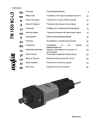
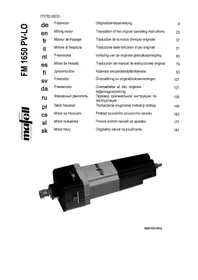
| Product type | Timber framing router |
| Brand | Mafell |
| Model | ZK 115 Ec |
| Service voltage | 230 V AC |
| Mains frequency | 50 Hz |
| Power consumption in continuous operation | 3000 W |
| Current consumption in continuous operation | 15,5 A |
| Idle speed | 4400 min-1 |
| Head pivot angle | 0 – 60° |
| Depth adjustment | 0 – 83,5 mm |
| Machine weight (without head or cable) | 21,1 kg |
| Weight of milling head ∅ 150 x 115 mm | 3,0 kg |
| Weight of milling head ∅ 236 x 50 mm | 3,5 kg |
| Weight of milling head ∅ 190 x 80 mm | 5,9 kg |
| Sound pressure level (LPA) | 101 dB(A) |
| Vibration (typical hand-arm) | 4,0 m/s2 |
| Standard equipment | Parallel guide, Phillips screwdriver, Torx T15 screwdriver, instructions, safety booklet, milling head ∅ 150 x 115 mm |
| Safety devices | Fixed upper guard, movable lower guard, movable upper guard, wide base, handles, control device and brake |
| Maintenance and cleaning | Regular cleaning, deresining of heads, checking the movable protective guard |
| Additional available accessories | Guide rails, milling heads ∅ 190 x 80 mm and ∅ 236 x 50 mm, adapters |
Frequently Asked Questions - ZK 115 Ec Mafell
User questions about ZK 115 Ec Mafell
0 question about this device. Answer the ones you know or ask your own.
Ask a new question about this device
Download the instructions for your Milling machine in PDF format for free! Find your manual ZK 115 Ec - Mafell and take your electronic device back in hand. On this page are published all the documents necessary for the use of your device. ZK 115 Ec by Mafell.
USER MANUAL ZK 115 Ec Mafell
natural_image
Exterior view of a Mafell CNC machine on a metal base (no signage or text in focus)WARNUNG
Please read all safety instructions and directions. Failure to comply with the safety instructions and directions can cause electric shock, fire and/or serious injuries. Please retain all safety instructions and directions for future reference.
AVERTISSEMENT
natural_image
Industrial machine component with numbered parts (31, 29, 27) shown below, no readable text or symbols on the device itself.MAF01156/a
natural_image
Mechanical device with numbered parts (29, 27, 31) and no visible text or symbols on the main body.MAF01156/a
MAF01156/a
MAF01156/a
MAF01156/a
natural_image
Mechanical device with numbered parts (33, 37, 34) shown in grayscale, no readable text or symbols on the device itself.MAF01156/a
GB - EC Declaration of Conformity
We herewith confirm that the machine ZK 115 Ec complies with the EU directives quoted. The standards listed were used for design and construction. Empowered person for the configuration of the technical documents: Mafell AG
$$ _ {W A} = 3, 0 \mathrm{dB(A)} $$
| 1 | Signs and symbols | 17 |
| 2 | Product information | 17 |
| 2.1 | Manufacturer's data | 17 |
| 2.2 | Machine identification | 17 |
| 2.3 | Technical data | 18 |
| 2.4 | Emissions | 19 |
| 2.5 | Scope of supply | 19 |
| 2.6 | Safety devices | 19 |
| 2.7 | Use according to intended purpose | 20 |
| 2.8 | Residual risks | 20 |
| 3 | Safety instructions | 20 |
| 4 | Setting / Adjustment | 22 |
| 4.1 | Mains connection | 22 |
| 4.2 | Tool change | 22 |
| 4.3 | Insert change | 22 |
| 5 | Operation | 23 |
| 5.1 | Initial operation | 23 |
| 5.2 | Switching on and off | 23 |
| 5.3 | Cutting bird's mouths | 23 |
| 5.4 | Cutting oblates, grooves and cones | 25 |
| 6 | Service and maintenance | 25 |
| 6.1 | Machine | 25 |
| 6.2 | Tools | 25 |
| 6.3 | Storage | 25 |
| 7 | Troubleshooting | 25 |
| 8 | Special accessories | 26 |
| 9 | Exploded drawing and spare parts list | 26 |
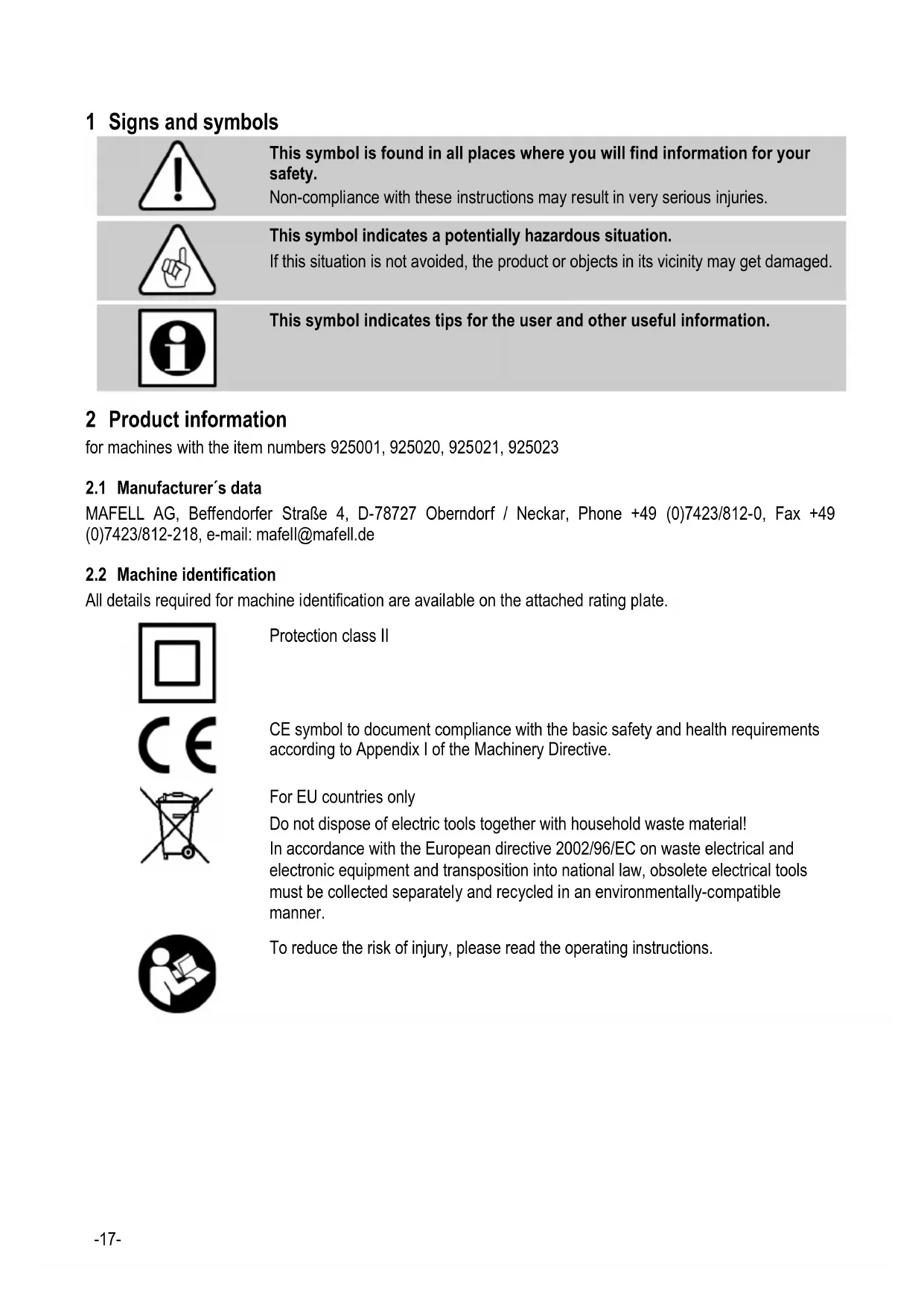
1 Signs and symbols

This symbol is found in all places where you will find information for your safety.
Non-compliance with these instructions may result in very serious injuries.

This symbol indicates a potentially hazardous situation.
If this situation is not avoided, the product or objects in its vicinity may get damaged.

This symbol indicates tips for the user and other useful information.
2 Product information
for machines with the item numbers 925001, 925020, 925021, 925023
2.1 Manufacturer's data
MAFELL AG, Beffendorfer Straße 4, D-78727 Oberndorf / Neckar, Phone +49 (0)7423/812-0, Fax +49 (0)7423/812-218, e-mail: mafell@mafell.de
2.2 Machine identification
All details required for machine identification are available on the attached rating plate.

Protection class II

CE symbol to document compliance with the basic safety and health requirements according to Appendix I of the Machinery Directive.
For EU countries only
Do not dispose of electric tools together with household waste material!
In accordance with the European directive 2002/96/EC on waste electrical and electronic equipment and transposition into national law, obsolete electrical tools must be collected separately and recycled in an environmentally-compatible manner.

To reduce the risk of injury, please read the operating instructions.
2.3 Technical data
| Operating voltage | 230 V AC |
| Mains frequency | 50 Hz |
| Input power continuous operation 3000 W | |
| Power consumption continuous operation | 15,5 A |
| Speed during idling 4400 rpm | |
| Can be pivoted from | 0 – 60° |
| Depth adjustment | 0 - 83.5 mm (0- 3 29/100 in.) |
Working tool
| for bird's mouths: | Cutter head ∅ 150 x 115 mm(5 29/32 x 4 17/32 in.) | n_max. = 5800 rpm |
| for flattening: | Cutter head ∅ 236 x 50 mm(9 29/100 x 1 97/100 in.) | n_max. = 5800 rpm |
| Cutter head ∅ 190 x 80 mm(7 31/64 x 3 5/32 in.) | n_max. = 5800 rpm |
| Weight | Machine with stop without cutter head and power cord | 21.1 kg (46.5 lbs) |
| Cutter head ∅ 150 x 115 mm | 3.0 kg (6.6 lbs) | |
| Cutter head ∅ 236 x 50 mm | 3.5 kg (7.7 lbs) |
Cutter head ∅ 190 x 80 mm 5.9 kg (13 lbs)
| Cutting speed with nominal load: | Cutter head ∅ 150 x 115 mm | 34,5 m/s (113 ft/sec.) |
| Cutter head ∅ 236 x 50 mm | 54,3 m/s (178 ft/sec.) | |
| Cutter head ∅ 190 x 80 mm | 43,8 m/s (144 ft/sec.) |
2.4 Emissions
The declared noise emission values have been measured in accordance with DIN EN 62841-1 and may be used for comparing the tool with another and also in a preliminary assessment of exposure.

Danger
The noise emissions during actual use of the power tool can differ from the declared values depending on the ways in which the tool is used especially what kind of workpiece is processed.
Always wear hearing protection, even when the power tool is running idle in addition to the trigger time!
2.4.1 Noise emission specifications
Noise emission values determined according to EN 62841:
Sound pressure level
$$ \mathrm{L} _ {\mathrm{PA}} = 1 0 1 \mathrm{dB(A)} $$
Uncertainty K
$$ _ {\mathrm{PA}} = 3, 0 \mathrm{dB(A)} $$
Sound power level L
$$ _ {P A} = 1 0 9 \mathrm{dB(A)} $$
Uncertainty
$$ K _ {P A} = 3, 0 \mathrm{dB(A)} $$
The noise measurements were made with the standard cutter head included in delivery.
Workpiece: Spruce 140 x 140 x 2000 mm; Cutting depth: 20 mm; Guide without stop
2.4.2 Vibration specifications
The typical hand-arm vibration is 4.0 m/s^2 .
2.5 Scope of supply
Carpentry bird's mouth cutter ZK 115 Ec complete with:
1 parallel stop
1 bird's mouth cutter head ∅ 150 x 115 mm (5 29/32 x 4 17/32 in.)
1 parallel stop
1 hex screwdriver
1 screwdriver Torx T 15
1 operating manual
1 folder "Safety Instructions"
2.6 Safety devices

Danger
These devices are required for the machine's safe operation and may not be removed or rendered inoperative.
Before operating the machine, check the safety devices for function and possible damage. Do not use the machine with missing or ineffective safety devices.
The machine is equipped with the following safety devices:
- Upper stationary saw guard
- Lower retractable saw guard
- Upper retractable saw guard
- Large base plate
- Handles
- Index mechanism and brake
2.7 Use according to intended purpose
The MAFELL ZK 115 Ec carpentry bird's mouth cutter is designed exclusively for working with wood.
For manual feeding use only tools that bear the MAN and, if applicable, the BG test label.
The dimensioning of the cutting and flattening heads used must correspond to the tools listed in this operating manual.
The tool was manufactured in accordance with the European norm EN 847-1.
Any other use than described above is not permissible.
The manufacturer cannot be held liable for any damage arising from such other use.
So as to use the machine as intended, comply with the operating, maintenance and repair instructions specified by Mafell.
2.8 Residual risks

Danger
Even if used in accordance with its intended purpose and despite conforming with the safety instructions, residual risks caused by the intended use that can lead to health consequences will always remain.
- Touching the cutter head in the area of the start-up opening.
- Touching the part of the cutter head that protrudes below the workpiece when cutting.
- Machine backlash if the blade gets stuck in the workpiece.
- Breakage and hurling out of the tool or parts of the tool.
- Touching live parts with the housing open and the mains plug not removed.
- Hearing can be impaired when working for long periods without ear protectors.
- Emission of hazardous wood dust when operating the machine for longer periods of time without extraction.
3 Safety instructions

Danger
Always observe the following safety instructions and the safety regulations applicable in the respective country of use!
Also read the safety instructions in the enclosed booklet "Safety instructions".
- Never work without the protective equipment required for the work to be undertaken and never modify anything on the machine that could impair safety.
- Children and adolescents must not operate this machine. This rule does not apply to young persons receiving training and being supervised by an expert.
- Before working with the machine, always check to ensure that the protective and safety devices are firmly in place and undamaged, that they work faultlessly and that the the moving protective hood works without getting stuck.
- Consider environmental influences. Do not expose the machine to rain and avoid working in damp and wet areas as well as near combustible liquids and gasses.
- When operating the machine outdoors, use of an earth-leakage circuit-breaker is recommended.
- Do not carry the machine by its cable and do not use the cable to pull the plug out of the socket outlet.
- Pay attention that the cable is protected against oil and heat and is not pulled across sharp edges.
- Damaged cables or plugs must be immediately replaced. Replacement may only be carried out by Mafell or an authorised MAFELL service workshop in order to avoid safety hazards.
- Avoid sharp bends in the cable. Especially when transporting and storing the machine, do not wind the cable around the machine.
- Use only cutter heads with the specifications indicated in this operating manual.
- Store the machine in a dry, locked place outside the reach of children.
Instructions on the use of personal protective equipment:
- Always wear ear protectors during work.
- Always where a dust mark during work.
- Always wear protective goggles during work.
Instructions on operation:
- The machine may be operated by one person only.
- Provide for an unobstructed and slip-proof location with adequate lighting.
- Unplug the power cord before changing tools, making adjustments or rectifying faults (including the removal of jammed chips).
- Do not work on workpieces which are too small or too large for the capability of the machine.
- Install and fasten the cutter head properly. Use sharp cutters and taper taps; dull cutters increase the risk of kickout. Immediately replace damaged cutters and taper taps and fasten them so that they cannot become loose operation.
- The moving protective hood must not be blocked when open.
- The switch may not be wedged.
- Before switching on the machine, always check whether the cutter head is tightened and whether the wrench and pin have been removed.
- If possible ensure that the workpiece is secured from slippage, e.g. with tension clamps.
- Hold firmly onto the machine before switching it on.
- Begin cutting the workpiece only when the cutter head reaches its full speed.
- Examine the workpiece for foreign objects. Do not cut into metal parts, e.g. nails.
- Never reach under the workpiece while cutting (risk of injury!).
- When cutting always have the connecting cable behind the machine.
- An even forward feed when cutting extends the service life of the cutting bit and the machine. Do not cut backwards or by dipping.
- Remove the machine from the workpiece only when the cutter head is at a standstill.
-
Never touch the cutter head or reach into the chip ejector while the machine is running. Always switch off the machine before making adjustments and ensure that the cutter head has come to a standstill.
-
Set the machine down only when the moving protective hood is closed. Do not clamp the moving protective hood or end guard, and ensure that they work properly. Do not remove protective parts.
- The bird's head cutter may be used only outside or in open areas, as effective extraction is not possible.
Instructions on service and maintenance:
- Regularly cleaning the machine, especially the adjusting devices and guides, constitutes an important safety factor.
- Only original MAFELL spare parts and accessories may be used. Otherwise the manufacturer will not accept any warranty claims and cannot be held liable.
4 Setting / Adjustment
4.1 Mains connection
Prior to commissioning make sure that the mains voltage complies with the operating voltage stated on the machine's rating plate.
4.2 Tool change

Danger
The operating speed must not exceed the maximum speed indicated on the tool.
Pay attention to the correct direction of rotation!
Clamp the tool so that it cannot become loose during operation. The tightening torque must be at least 30 Nm.
The blades must touch neither each other nor the clamping pieces.
Pay attention to cleanliness when changing tools. Clamping surfaces must have been cleaned from any soiling, grease, oil and water.
The tightening torque must be checked during installation, before every recommissioning and at regular intervals during longer lasting processing. Use a suitable torque wrench for the inspection.
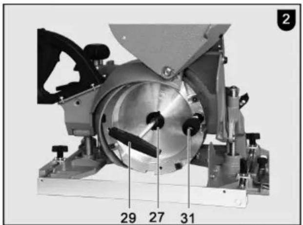
- Lock the tool with pin 31 (fig. 1+2).
- Use the hexagon screwdriver 29 to unscrew the cylinder head screw anticlockwise, remove front flange 27 and cutter head.
- Clean chips and dusts off the spindle and clamping surfaces and put the tool on. When doing so ensure that both drive pins on the spindle engage both bore holes on the tool.
- Insert the cylinder head screw with flange and tighten firmly with the hexagonal screwdriver.
- Remove the pin and hexagonal screwdriver.

Danger
Idle speed of the output shaft = 4400 rpm, therefore install only cutter heads with n ≥ 5800 rpm.
4.3 Insert change

Danger
Always pull the power plug before making changes or adjustments. Install and remove the cutters in accordance with the instructions in the operating manual. Utmost caution is mandatory!
Clamping surfaces must have been cleaned from any soiling, grease, oil and water.
Observe the specified tightening torques! The clamping screws must be tightened only with the tools provided or with a tool of the same dimensions. No striking tools, levers, extensions or other tools may be used.
All blades must always be fitted in order to prevent imbalance.
The cutter or flattening head must be fitted with replaceable hard metal cutting inserts. Time-consuming sharpening is unnecessary as the hard metal cutting inserts need to be only turned or replaced when the blades are dull.
- Remove the tool from the machine (see section 4.2).
- Loosen the screwed on hard metal cutting inserts with the spanner included in delivery, turn 90 degrees and tighten again° (4Nm) or, after turning three times, replace with new cutting inserts.
- Clean all parts and the blade chamber in the cutter head.

Aluminium tools may only be deresinified with solvents which do not corrode the aluminium.
• Re-install the tool (see section 3.2).
- After installing new indexable inserts or changing the cutting side, make sure that the surface
produced is uniform. An uneven appearance is an indication of incorrectly mounted indexable inserts. Correct the position of the indexable inserts.
5 Operation
5.1 Initial operation
Personnel entrusted to work with the machine must be made aware of the operating instructions, calling particular attention to the chapter "Safety instructions".
It is mandatory to check whether all safety devices are attached and functional. This applies especially to the ease of movement of the protective hood.
5.2 Switching on and off

Danger
Before switching the machine on ensure that the cutter head can move freely and that the moving protective hood is closed.
Lead the connecting cable away to the rear.
Take hold of the machine by the handles.
Switch the machine on only when the cutter head is not in contact with the workpiece.
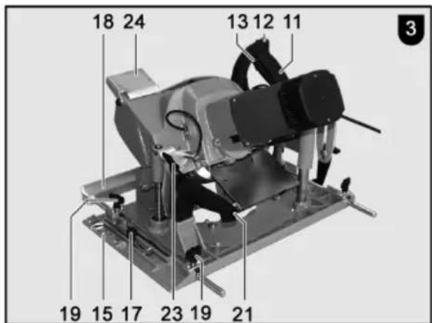
- Switching on: First unlock the switch lock by pressing the locking lever 12 (fig. 3). Then actuate the shift lever 13 while pressing the locking lever. As this is a switch without locking device, the machine will only run for as long as this gearshift lever is pressed.
The built-in electronic system provides for jerk-free acceleration when the machine is switched on and under load readjusts the speed to the fixed setting.
This electronic system also controls the motor upon overload, e.g. the cutter head stays still. The machine must then be unloaded until the cutter head has reached its full speed. Then continue to cut at a lower feed rate.
Switching off: Release the switch lever 13 to switch the machine off. The built-in automatic break limits the run-down time of the cutter head to approx. 5 s. The switch lock takes effect automatically and secures the bird's mouth cutter from inadvertently being switched on again.
5.3 Cutting bird's mouths
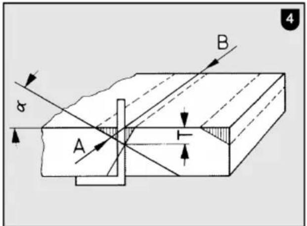
5.3.1 Mark bird's mouth
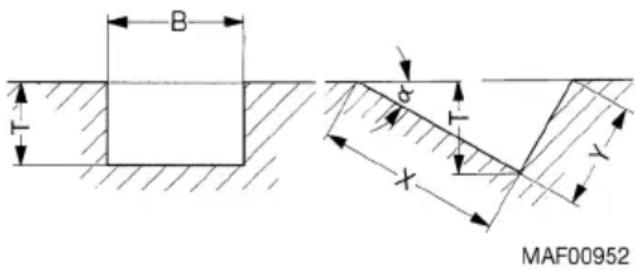
Angle and mark the two-sided bird's mouth mark at the intersection. Pull the crevice A – B (fig. 4) over the rafter.
5.3.2 Setting bird's mouth cutter
The following settings must be made before using the machine:
- Set the bird's mouth angle "α":
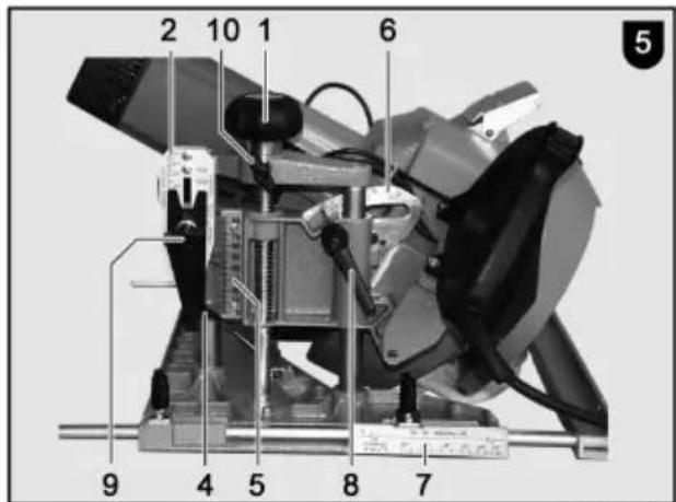
The cutter head can be pivoted from 0 – 60°. Release the clamping lever 8 (fig. 5) and set the angle value (e.g. 30°) on the angle scale. Tighten the clamping lever; The clamping position of the lever can be set by pulling it out in a vertical direction.
- Set the depth indicator:
The cutter depth indicator depends on the set bird's mouth angle "α". The depth indicator 4 can therefore be set from 0 – 60° and must always be set to the same angle value "α" as angle scale 6. Loosen the handle knob 9. Move the depth indicator 4 on the left side of setting scale 2 (marked "cutter head ∅ 150 x 115") to the desired angle value "α" (the upper edge is the reading line) and the tighten the handle knob again.
- Set the cutter depth to 0:
Unscrew the wing screw 10 (fig. 5). Turn the handle 1 until the depth indicator 4 on the depth scale 5 is at zero. Tighten the wing screw 10 (fig. 5).

The corner of the cutter of the pivoted cutter head must be positioned at the same level as the base panel support.
- Set the mark indicator: The mark indicator 16 (fig. 3) shows the position of the corner of the blade at the horizontal level. It must therefore always be set to the same angle value "α" as the angle scale 6 (fig. 5). Loosen the knurled knob 17 (fig. 3). Set the mark indicator 16 with the outer right edge over the mark scale 15 in the area of the marking "Set cutter head ∅ 150 x 115» to angle value 'α''. Tighten the knurled knob 17.

The angle scale 6 (fig. 5), depth indicator 4 and mark indicator 16 (fig. 3) must always be set to the same value "α".
- Parallel stop: The parallel stop 18 (fig. 3) can be set after loosening the wing screws 19, and it can be used on the left or right side.
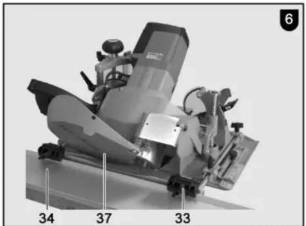
- Set the machine to the mark: Open the moving protective hood by pressing the lever 23 (fig. 3) and set the machine onto the wood in such a way that the end guard 37 (fig. 6) swivels back. The bird's mouth angle, depth indicator (cutter depth 0mm ) and mark indicator must be set in advance. With respect to the space available, align the guide rails 34 (fig. 6) parallel left or right with spacing to the mark A - B (fig. 4) and fasten.
Spacing between the mark and rail approx.:
to the right
10 cm (3 15/16
in.)/30°
15 cm(5 15/16 in.)/45°
20 cm (7 7/8 in.)/60°
to the left
32 cm (12 9/16
in.)/30°
30 cm (11 3/16
in.)/45°
27 cm (10 5/8 in.)/60°
Tighten adapter 33 (fig. 6) on the parallel stop 18. Set the machine with the adapter on the guide rail and align it to the mark indicator on mark A - B (fig. 4) by moving it to the side in the parallel stop guides. Tighten the wing screws 19 (fig. 3). Check the mark on the rear mark scale 7 (fig. 5).
5.3.3 Cutting bird's mouth
- Unscrew the wing screw 10 (fig. 5). Remove the machine from the guide rail. Set cutter depth "T" (fig. 4) by turning the handle 1 (fig. 5) to the desired dimension in accordance with depth scale 5. - Tighten the wing screw 10 (fig. 5) again. Set the machine with the adapter on the guide rail so that the cutter head with the protective hood is exposed. Switch on the machine. Open the moving protective hood by pressing the lever 23 (fig. 3) and cut with a uniform feed rate. The ejected chips can be deflected by setting the chip deflector 24. Guide the machine using both handles 11 and 21.

When done using the machine ensure that the moving protective hood is closed again.
5.3.4 Milling dimensions
| Cutterhead | 150 × 115 (5 29/32 × 4 17/32 in.) | 236 x50 (929/100 x197/100in.) | 190x 80(731/64 x 35/32in.) | ||||
| 0 | |||||||
5.4 Cutting oblates, grooves and cones
- Set angle scale 6 (fig. 5) and mark indicator 16 (fig. 3) to 0. Depending on the cutter head user, set the depth indicator 4 (fig. 5) to the left or right half of the setting scale 2 (with a cutter head of ∅ 236 or 190 mm to the corresponding markings on the right, with a cutter head of ∅ 150 mm to the left). The cutter width, which at first comprises the width of cutter head, can be increased by moving the parallel stop laterally 18 (fig. 3).
6 Service and maintenance

Danger
Pull the power plug during all service work.
MAFELL machines are designed to be low in maintenance.
The ball bearings used are greased for life. When the machine has been in operation for a longer period of time, we recommend to hand the machine in at an authorised MAFELL customer service shop for inspection.
Only use our special grease, order No. 049040 (1 kg tin) for all greasing points.
6.1 Machine
The machine must be regularly cleaned off deposited dust. The ventilation openings on the motor should be cleaned with a vacuum cleaner.
The free movement of the moving protective hood must be ensured. If it does not close by itself after it is opened, the machine must be delivered to an authorised MAFELL customer service workshop.
6.2 Tools
The cutter heads used on the machine should be regularly deresinified, as clean tools improve improve the cutting quality.
Deresinify them by placing them in petroleum or a commercially available deresinification agent for 24 hours.

Aluminium tools may only be deresinified with solvents which do not corrode the aluminium.
Promptly replace damaged clamping screws and cutting elements.
The design must not be modified with progressive tools during servicing.
6.3 Storage
Clean the machine thoroughly if the machine is not used for a longer period of time. Spray blank metal parts with a rust-proofing agent.
Store the machine only in dry rooms and protect it from the effects of weather.
7 Troubleshooting

Danger
Determining the causes for existing defects and eliminating these always requires increased attention and caution. Pull the mains plug beforehand!
Some of the most frequent defects and their causes are listed in the following chart. In case of other defects, contact your dealer or the MAFELL customer service.
| Defect | Cause | Elimination |
| Machine cannot be switched on | No mains voltage | Check power supply |
| Mains fuse defective | Replace fuse | |
| Carbon brushes worn | Take the machine to a MAFELL customer service shop | |
| Machine switches off automatically during idling or stops during cutting | Mains failure | Check mains back-up fuses |
| Machine overloaded | Reduce feed speed |
8 Special accessories
- Guide rail length 3 m (2 parts with connector) Order No. 037037
- Guide rail length 3 m (1 part) Order No. 200672
- Guide rail extension length 1.5 m Order No. 036553
- Adapter pair for parallel stop Order No. 037195
- Complete bird's mouth cutter head ∅ 190 x 80 mm Order No. 091417
- Complete flattening head ∅ 236 x 50 mm Order No. 203659
9 Exploded drawing and spare parts list
The corresponding information in respect of spare parts can be found on our homepage: www.mafell.com
Français
Sommaire
$$ _ {W A} = 3, 0 \mathrm{dB(A)} $$
$$ _ {W A} = 3, 0 \mathrm{dB(A)} $$
$$ _ {W A} = 3, 0 \mathrm{dB(A)} $$
Meranie hluku bolo realizované so štandardne dodávanou hlavou frézy.
Obrobok: Smrek 140 x 140 x 2000 mm; híbka frézovania: 20 mm; vedenie bez dorazu
MAFELL AG
Beffendorfer Straße 4, D-78727 Oberndorf / Neckar
Telefon +49 (0)7423/812-0
Internet:
E-Mail:
Fax +49 (0)7423/812-218
www.mafell.de
mafell@mafell.de

- WARNUNG
- AVERTISSEMENT
- GB - EC Declaration of Conformity
- Signs and symbols
- Product information
- Manufacturer's data
- Machine identification
- Emissions
- Danger
- Noise emission specifications
- Vibration specifications
- Scope of supply
- Safety devices
- Use according to intended purpose
- Residual risks
- Safety instructions
- Instructions on the use of personal protective equipment:
- Instructions on operation:
- Instructions on service and maintenance:
- Setting / Adjustment
- Mains connection
- Tool change
- Insert change
- Operation
- Initial operation
- Switching on and off
- Cutting bird's mouths
- Mark bird's mouth
- Setting bird's mouth cutter
- Cutting bird's mouth
- Cutting oblates, grooves and cones
- Service and maintenance
- Machine
- Tools
- Storage
- Troubleshooting
- Special accessories
- Exploded drawing and spare parts list
- Français
- Sommaire
Brand : Mafell
Model : ZK 115 Ec
Category : Milling machine