
TEC 29 - Generator DOMETIC - Free user manual and instructions
Find the device manual for free TEC 29 DOMETIC in PDF.

| Product type | Gasoline generator for motorhome and caravan |
| Brand | Dometic |
| Model | TEC 29 (ref. 9102900299) |
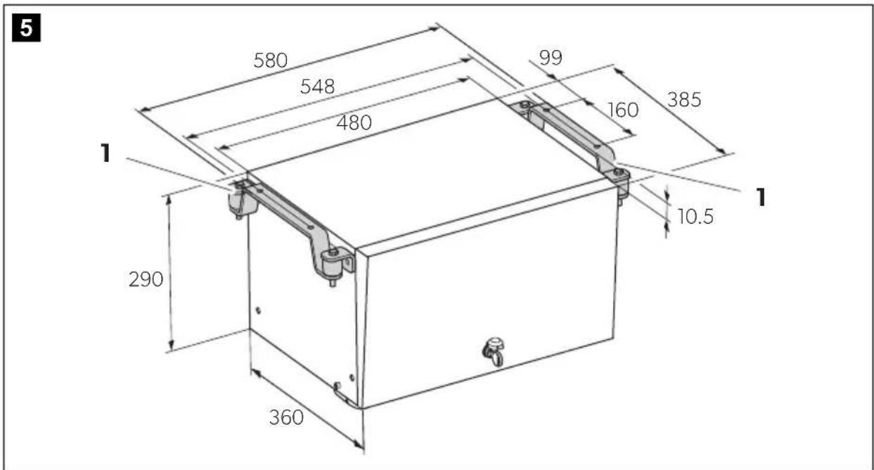
| Dimensions | See installation diagram (figure 5 of the manual) |
| Weight | 44 kg (dry mass) |
| Output voltage | 230 V~ / 50 Hz (pure sine wave) |
| Max. continuous power | 2600 W (at 300 m altitude, 30 % relative humidity) |
| Power reduction | 5 % per 5 °C and 3.5 % per additional 300 m altitude |
| Battery charger | 12 V, max. current 10 A |
| Fuel | Regular unleaded gasoline ROZ 91 |
| Consumption | Max. 1.2 l/h |
| Engine power | 3.6 kW (4.9 hp) at 3600 rpm |
| Operating temperature | -15 °C to +50 °C |
| Starter battery | 12 V, min. capacity 60 Ah |
| Main functions | 230 V backup power supply, 12 V battery charger, automatic mode, priority connection, parallel connection possible |
| Maintenance and cleaning | Regular oil change, air and fuel filter replacement, oil level check |
| Safety | Thermal circuit breaker, oil level gauge, overvoltage protection, automatic shutdown in automatic mode |
| Spare parts and repairability | Original spare parts available, repair by qualified personnel only |
| General information | Indoor or outdoor installation, remote control included, optional tank, compliant with VDE standards |
Frequently Asked Questions - TEC 29 DOMETIC
User questions about TEC 29 DOMETIC
0 question about this device. Answer the ones you know or ask your own.
Ask a new question about this device
Download the instructions for your Generator in PDF format for free! Find your manual TEC 29 - DOMETIC and take your electronic device back in hand. On this page are published all the documents necessary for the use of your device. TEC 29 by DOMETIC.
USER MANUAL TEC 29 DOMETIC
natural_image
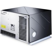
Exterior view of a metallic Dometriary box (no signage or text visible on body)TEC29 EV
EN Generator
Installation Manual....17
DE Generator
© 2021 Dometic Group. The visual appearance of the contents of this manual is protected by copyright and design law. The underlying technical design and the products contained herein may be protected by design, patent or be patent pending. The trademarks mentioned in this manual belong to Dometic Sweden AB. All rights are reserved.
natural_image
Technical line drawing of a rectangular electronic enclosure with mounting feet and upward arrows indicating force or movement (no text or symbols)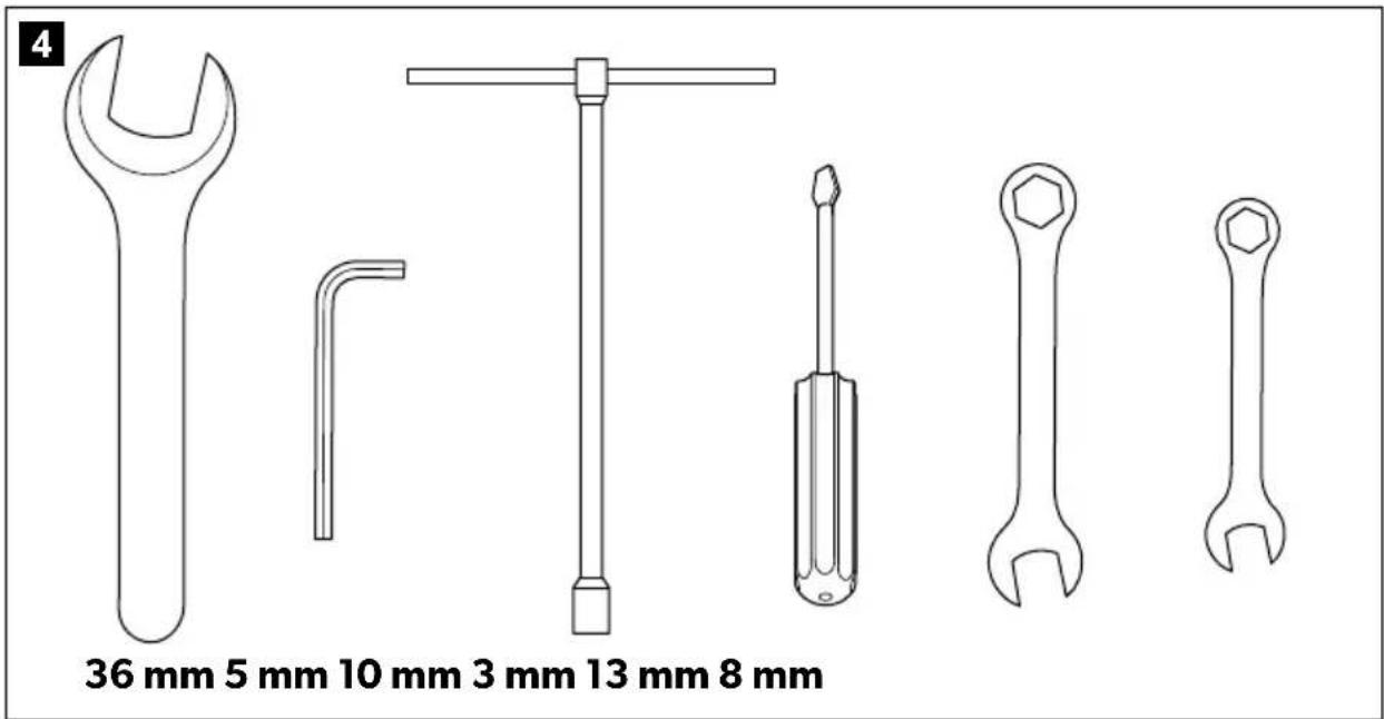
natural_image
Technical line drawing of a mechanical assembly with pipes, valves, and a central component (no text or symbols)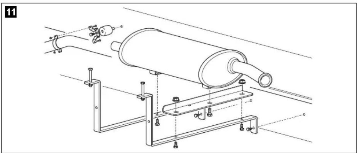
natural_image
Technical line drawing of a mechanical assembly with pipes and clamps (no text or symbols)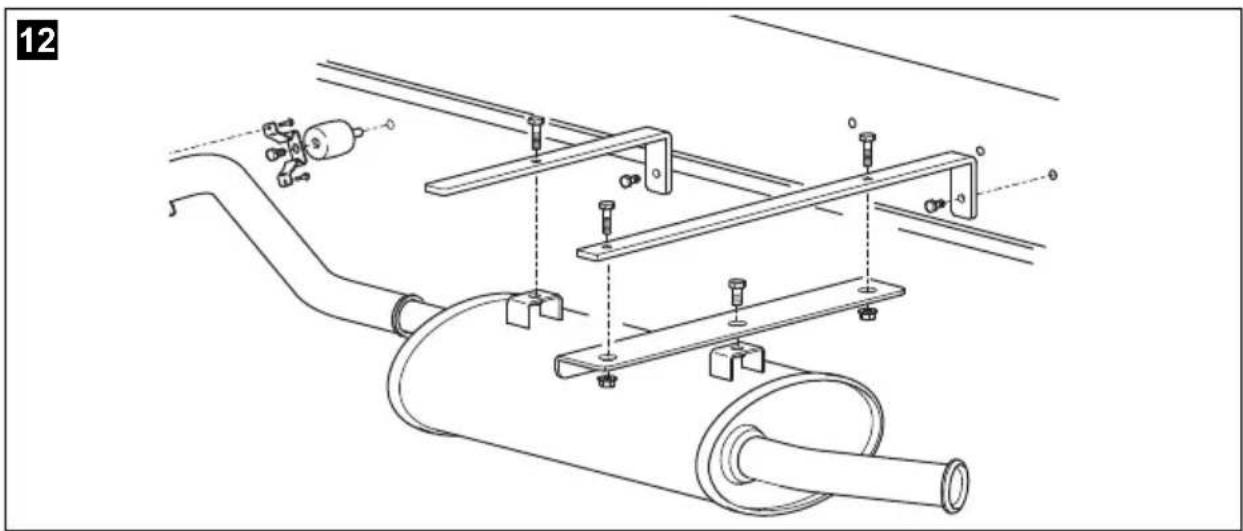
natural_image
Technical line drawing of a mechanical assembly with pipes, bolts, and a valve (no text or symbols)13
natural_image
Technical line drawing of a mechanical assembly with pipes, valves, and a housing (no text or symbols)14
17
18
| bl br cy ge gn gr | ||||||
| EN Blue Brown Cyan Yellow Green Grey | ||||||
| DE Blau Braun Cyan Gelb Grün Grau | ||||||
| FR | Bleu | Marron | Cyan | Jaune | Vert | Gris |
| ES | Azul | Marrón | Cian | Amarillo | Verde | Gris |
| PT | Azul | Castanho | Ciano | Amarelo | Verde | Cinzento |
| IT | Blu | Marrone | Cyan | Giallo | Verde | Grigio |
| NL | Blauw | Bruin Cyaan | Geel Groen Grijs | |||
| DA | Blå | Brun | Cyan | Gul | Grøn | Grå |
| SV | Blå | Brun | Cyan | Gul | Grøn | Grå |
| NO | Blå | Brun | Cyan | Gul | Grønn | Grå |
| FI | Sininen | Ruskea | Syaani | Keltainen | Vihreå | Harmaa |
| RU | Синий | Коричневый | Голубой | Желтый | Зеленый | Серый |
| PL | Niebieski | Brązowy | Cyjan | Žółty | Zielony | Szary |
| SK | Modrá | Hnedá | Azúrová | Žltá | Zelená | Sivá |
| CS | Modrá | Hněda | Azurová | Žlutá | Zelená | Šedá |
| HU Kék | Barna Cián Sárga Zöld Szürke | |||||
| or | pk | rt sw vt ws | ||||
| EN | Orange | Pink | Red | Black | Violet | White |
| DE | Orange | Pink | Rot | Schwarz | Violett | Weiß |
| FR | Orange | Rosa | Rouge | Noir | Violeta | Blanc |
| ES | Naranja | Rose | Rojo | Negro | Lila | Blanco |
| PT | Cor de laranja | Cor de rosa | Vermelho | Preto | Violeta | Branco |
| IT | Arancione | Rosa | Rosso | Nero | Violetto | Bianco |
| NL | Oranje Roze | Rood Zwart Paars Wit | ||||
| DA | Orange | Lyserøde | Rød | Sort | Violet | Hvid |
| SV | Orange | Rosa | Röd | Svart | Violett | Vit |
| NO Oransje Rosa Rød | Svart Fiolett Hvt | |||||
| FI | Oranssi | Pinkki | Punainen | Musta | Violetti | Valkoinen |
| RU | Оранжевый | Розовый | Красный | Черный | Фиолетовый | Бепый |
| PL | Pomarańczowy | Różowy | Czerwony | Czarny | Fioletowy | Biały |
| SK | Oranžová | Ružová | Červená | Čierna | Fialová | Biela |
| CS | Oranžová | Růžová | Červená | Černá | Fialová | Bílá |
| HU | Narancs | Rózsaszín | Piros | Fekete | Ibolya | Fehér |
Please read these instructions carefully and follow all instructions, guidelines, and warnings included in this product manual in order to ensure that you install, use, and maintain the product properly at all times. These instructions MUST stay with this product.
By using the product, you hereby confirm that you have read all instructions, guidelines, and warnings carefully and that you understand and agree to abide by the terms and conditions as set forth herein. You agree to use this product only for the intended purpose and application and in accordance with the instructions, guidelines, and warnings as set forth in this product manual as well as in accordance with all applicable laws and regulations. A failure to read and follow the instructions and warnings set forth herein may result in an injury to yourself and others, damage to your product or damage to other property in the vicinity. This product manual, including the instructions, guidelines, and warnings, and related documentation, may be subject to changes and updates. For up-to-date product information, please visit documents.dometic.com, dometic.com.
Table of contents
1 Explanation of symbols....17
2 Safety and installation instructions .....18
3 Target group for this manual....19
4 Scope of delivery 20
5 Accessories 20
6 Intended use....21
7 Labels....21
8 Technical description 22
9 Installation 23
10 Connecting the electrical power to the generator 26
11 Disposal.... 32
12 Technical data 33
1 Explanation of symbols

DANGER!
Safety instruction: Indicates a hazardous situation that, if not avoided, will result in death or serious injury.

WARNING!
Safety instruction: Indicates a hazardous situation that, if not avoided, could result in death or serious injury.

CAUTION!
Safety instruction: Indicates a hazardous situation that, if not avoided, could result in minor or moderate injury.

NOTICE!
Indicates a situation that, if not avoided, can result in property damage.

NOTE
Supplementary information for operating the product.
2 Safety and installation instructions
Please observe the prescribed safety instructions and stipulations from the vehicle manufacturer and service workshops.
Note the following basic safety information when using electrical devices to protect against:
- Electric shock
- Fire hazards
- Injury
2.1 Using the device

WARNING!
- Installing and repairing the device may only be carried out by qualified personnel who are familiar with the risks involved and the relevant regulations. Inadequate repairs may cause serious hazards. For repair service, please contact the service centre in your country (addresses on the back page).
• Electrical devices are not toys
Keep electrical devices out of reach of children or infirm persons. Do not allow them to use electrical devices without supervision.
- People (including children) whose physical, sensory or mental capacities prevent them from using this device safely may not be allowed to operate it without the supervision of a responsible adult.
- Exhaust fumes contain carbon monoxide which is a highly toxic, odourless and colourless gas. Do not inhale any exhaust fumes. Do not leave the generator motor running in a closed garage or in a room without windows.

CAUTION!
- Fire hazards
Do not install the generator in a box or room without any openings, but in well-ventilated spaces instead.
- Only operate the generator if you are certain that the housing and the cables are undamaged.
• Install the generator on a stable surface. - Do not tilt the generator more than 20^ from the vertical position.

NOTICE!
- Only use the device as intended.
- The generator is not suitable for use in water vessels.
- Do not make any alterations or conversions to the device.
- If a welding operation has been done on the vehicle disconnect all generator cables, otherwise the electronics may be damaged.
2.2 Handling electrical cables

WARNING!
- The electrical power supply may only be connected by a qualified electrician (e.g. according to VDE 0100, Part 721 in Germany).

CAUTION!
- Attach and lay the cables so that they cannot be tripped over or damaged.

NOTICE!
- Use cable ducts to lay cables through walls with sharp edges.
- Do not lay loose or bent cables next to electrically conductive materials (metal).
- Do not pull on the cables.
3 Target group for this manual
The instructions in this manual are intended for qualified personnel at workshops who are familiar with the guidelines and safety precautions to be applied.
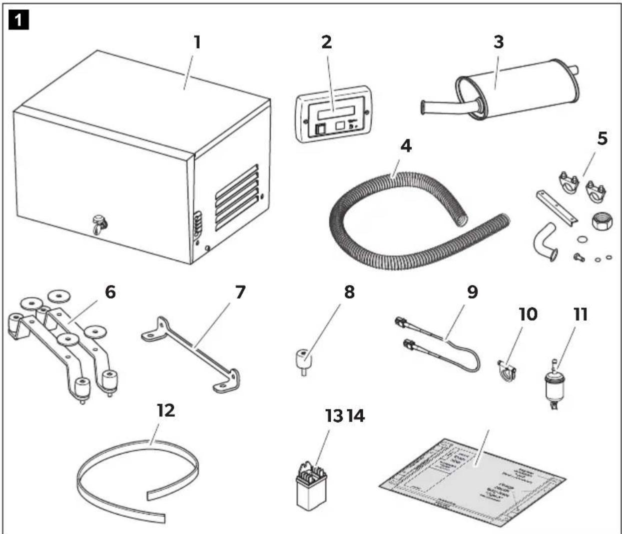
4 S c o p e o f d
No. in
fig. 1,
page 3
Number Description
11 Generator
21 Remote control
31 Silencer
41 Exhaust pipe, 2 m
51 set Mounting brackets for silencer
61 set Retaining brackets for external installation
7 2 Holders for internal installation
8 4 Spacers
9 1 Extension cable for remote control, 5 m
10 1 Hose clamp
11 1 Fuel filter
121 AG 128, seal
13 1 AG 102, changeover relay for making priority circuits
14 1 Cut off template
5 A c c e s s o r i
Available as accessories (not included in the scope of delivery):
Part designation Ref. number
AG 101, tank 15 l, plastic 9102900009
AG 100, tank 20 l, stainless steel 9102900011
AG 117, tank 15 l, plastic, with brackets and integrated mouth and cap 9102900010
AG 150, pipe set for AG 100 / AG 101 9102900003
AG 125, flexible metal pipe for extending exhaust pipe, 5 m 9102900138
AG 113, change over switch for parallel connection 9102900015
Parallel cable 9102900296
6 Intended use
The TEC29 EV (reference no. 9102900299) generator is designed for use in motor homes, camper vans and vehicles for commercial use.
The generator is not suitable for installation in water vessels.
The generator produces a pure sine wave voltage of 230 V/50 Hz which can be connected to the consumer with a total continuous load of 2600 W. The power quality is also suitable for sensitive consumers (such as PCs).
Before installation the genset has to be stored in the original box in a clean ambiance with low humidity and an ambient temperature from -20 ^ to +55 ^ .
The generator can charge a 12 V battery.
This product is only suitable for the intended purpose and application in accordance with these instructions.
This manual provides information that is necessary for proper installation and/or operation of the product. Poor installation and/or improper operating or maintenance will result in unsatisfactory performance and a possible failure.
The manufacturer accepts no liability for any injury or damage to the product resulting from:
- Incorrect assembly or connection, including excess voltage
- Incorrect maintenance or use of spare parts other than original spare parts provided by the manufacturer
• Alterations to the product without express permission from the manufacturer - Use for purposes other than those described in this manual
Dometic reserves the right to change product appearance and product specifications.
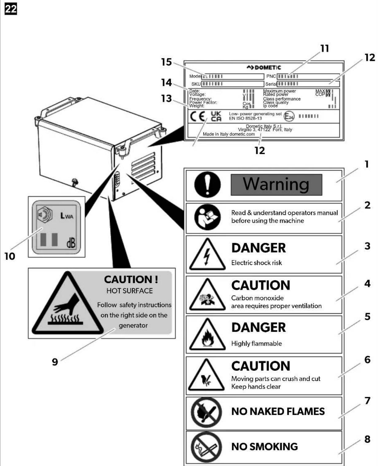
7 L a b e l s
Labels are attached to the generator. These labels provide the user and fitter with information on the device specifications.
Explanation of pictograms (fig. 22, page 15):
| No. in fig. 22, Description page 15 |
| 1 Warning |
| 2 Read and understand operators manual before using |
| 3 Danger – Electric shock risk |
| 4 Caution – Carbon monoxide – Area requires proper ventilation |
| 5 Danger – Highly flammable |
| 6 Caution – Moving parts can crush and cut – Keep hands clear |
| 7 No naked flames |
| 8 No smoking |
| 9 Caution – Hot surface – Follow safety instructions on the right side of the generator |
| 10 Noise label – Value of the guaranteed sound power level |
| 11 Part number code |
| 12 Serial number |
| 13 Manufacturer and address |
| 14 CE and UK mark |
| 15 Dry mass |
| 16 Year of production |
| 17 Generator model |
8 Technical description
Installing the generator must be configured according to one of the following options:
- Automatic mode switch, see chapter "Configuring the automatic mode" on page 30.
- Priority circuit which prioritises the 230 V external voltage over the voltage produced by the generator, see chapter "Creating a priority circuit" on page 31.
9 Installation

CAUTION! Beware of injury
The generator may only be installed by qualified personnel from a specialist company. The following information is intended for technicians who are familiar with the guidelines and safety precautions to be applied.
9.1 Note on installation
Read the installation manual carefully before you install the generator.
When installing the generator, note the following:

DANGER! Danger of electrocution
Disconnect all power supplies when working on the generator.

CAUTION! Beware of injury
- Improper installation of the generator can result in irreparable damage to the device and put the safety of the user at risk.
- Always wear the recommended protective clothing (e.g. protective goggles, gloves).
9.2 Securing the generator
Note on installation location
- Make sure that no combustible objects are stored or installed near the air outlet or the ventilation slots. A distance of at least 50 cm should be kept.
- For a correct ventilation keep a distance of at least 30 cm from the generator's air outlet.
- For safety reasons, note the location of existing wiring harnesses, wires and other components within the installation area, in particular those which are not visible, when installing the generator (when drilling or screwing etc.).
You can secure the generator with the holders supplied in two ways.
9.3 External installation
- To find a position where is possible to install the generator, take into consideration:
– Distance from ground - Considering the drilling needed
– Far enough from vehicle exhaust
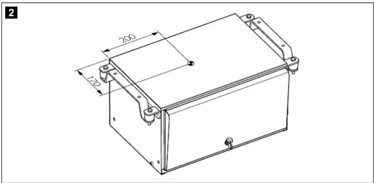
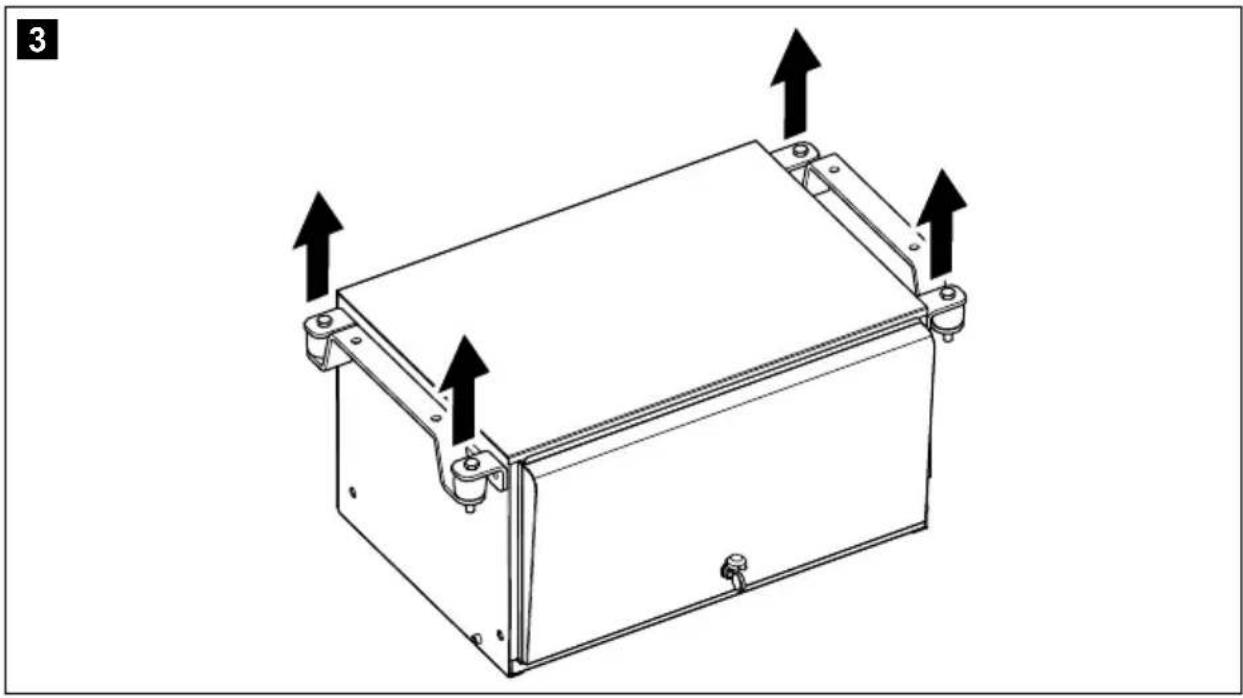
– Easy serviceability access - Mind the center of gravity (fig. 2, page 3) and the lifting points (fig. 3, page 4) indicated.
- Use the tools shown to install the generator (fig. 4, page 4).
- To ensure the generator is attached securely, use the retaining bracket (fig. 5, page 5) supplied.
Remove the generator from its chassis
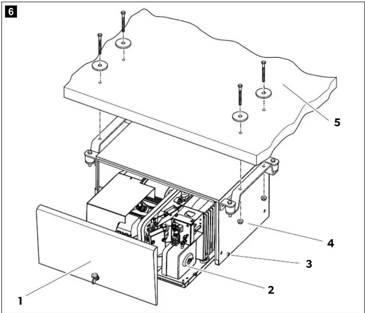
▶ Remove the front access (fig. 6 1, page 5).
▶ Remove the two fixing lateral screws (fig. 6 3, page 5).
▶ Slide out the generator (fig. 6 2, page 5).
Install the enclosure on vehicle
▶ Drill the vehicle floor on the chosen position using the cut off template 8 mm diameter.
▶ Fix the enclosure with a 8 mm bolt system with washers provided.
▶ Slide in the generator on the chassis and fix it with the two lateral screws (fig. 6 3, page 5).
9.4 Internal installation
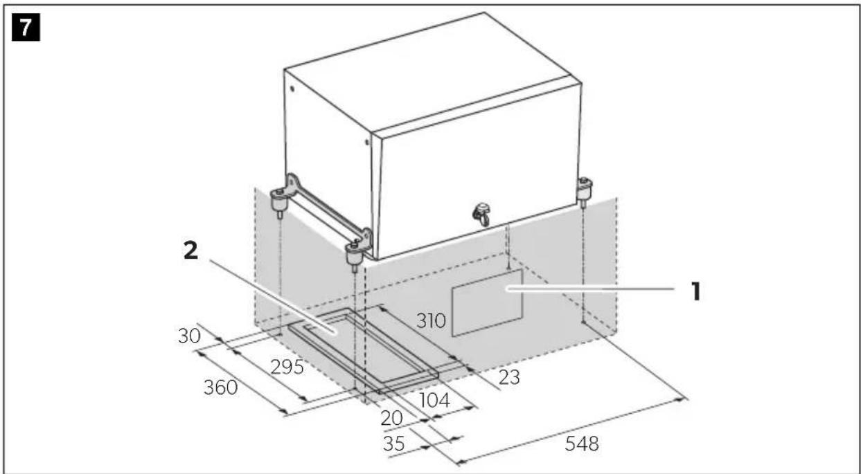
- For internal installation, you need to prepare a sealed compartment against the vehicle interior which can also be insulated against sound (fig. 7, page 6).
- Leave a space of at least 20 mm between the generator hood and surrounding parts so that sufficient space remains for cooling air to pass through.
Remove the generator from its chassis
▶ Remove the front access (fig. 6 1, page 5).
▶ Remove the two fixing lateral screws (fig. 6 3, page 5).
▶ Slide out the generator (fig. 6 2, page 5).
Install the chassis on vehicle
▶ Drill the vehicle floor on the chosen position using the cut off template 8 mm diameter (fig. 6 5, page 5).
▶ Use the indication of the cut off template to make the openings for the exhaust and air outlet.
▶ Fit the seal provided all around the exhaust and air outlet, between the floor of the vehicle and the generator.
▶ Fix the chassis to the floor of the vehicle using four 8 mm nuts (fig. 6 4, page 5).
▶ Slide in the generator on the chassis and fix it with the two lateral screws (fig. 6 3, page 5).
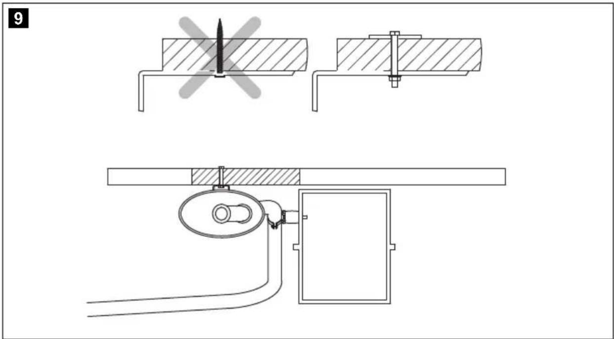
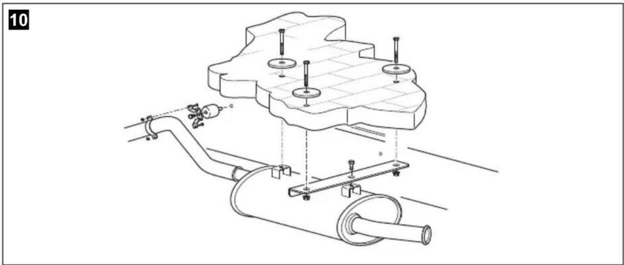
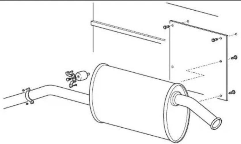
9.5 Securing the silencer
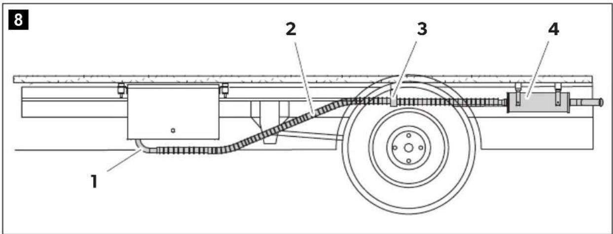
Observe the following instructions when installing the exhaust pipe:
- Do not create any sharp bends which will inhibit the flow of exhaust fumes.
- Align the manifold (fig. 8 1, page 6) along the housing to ensure greater damping of vibration.
- Use the exhaust pipe extension to extent the exhaust pipe (fig. 8 2, page 6) (see chapter "Accessories" on page 20).
Secure the extension to the vehicle floor (fig. 8 3, page 6).
▶ Secure the silencer (fig. 8 4, page 6) as in one of the alternatives shown in fig. 9, page 6 to fig. 13, page 8.
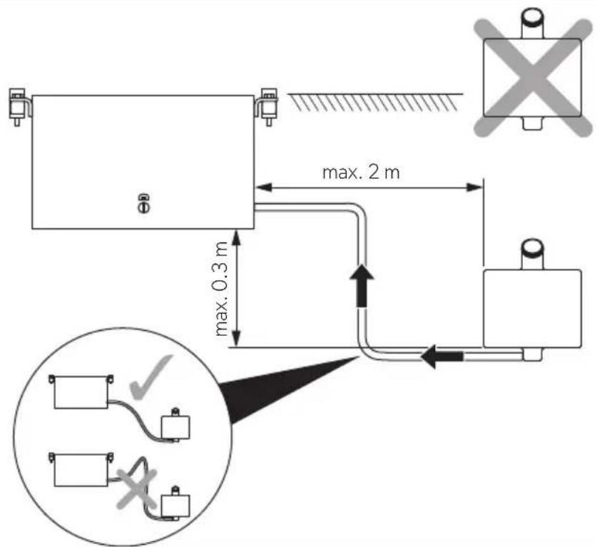
9.6 Installing the tank and fuel supply line

NOTE
The additional tank has to be installed far from hot surfaces and has to be installed to avoid any fuel leakage.
Please observe the following instructions for the installation location:
- The tank bottom must be positioned at a maximum of 0.3 m below the bottom of the generator.
- The top of the tank must not be higher than the top of the generator.
▶ Lay the fuel line as straight as possible.
▶ Secure the tank, see fig. 14, page 8 and chapter "Connecting the float" on page 31.
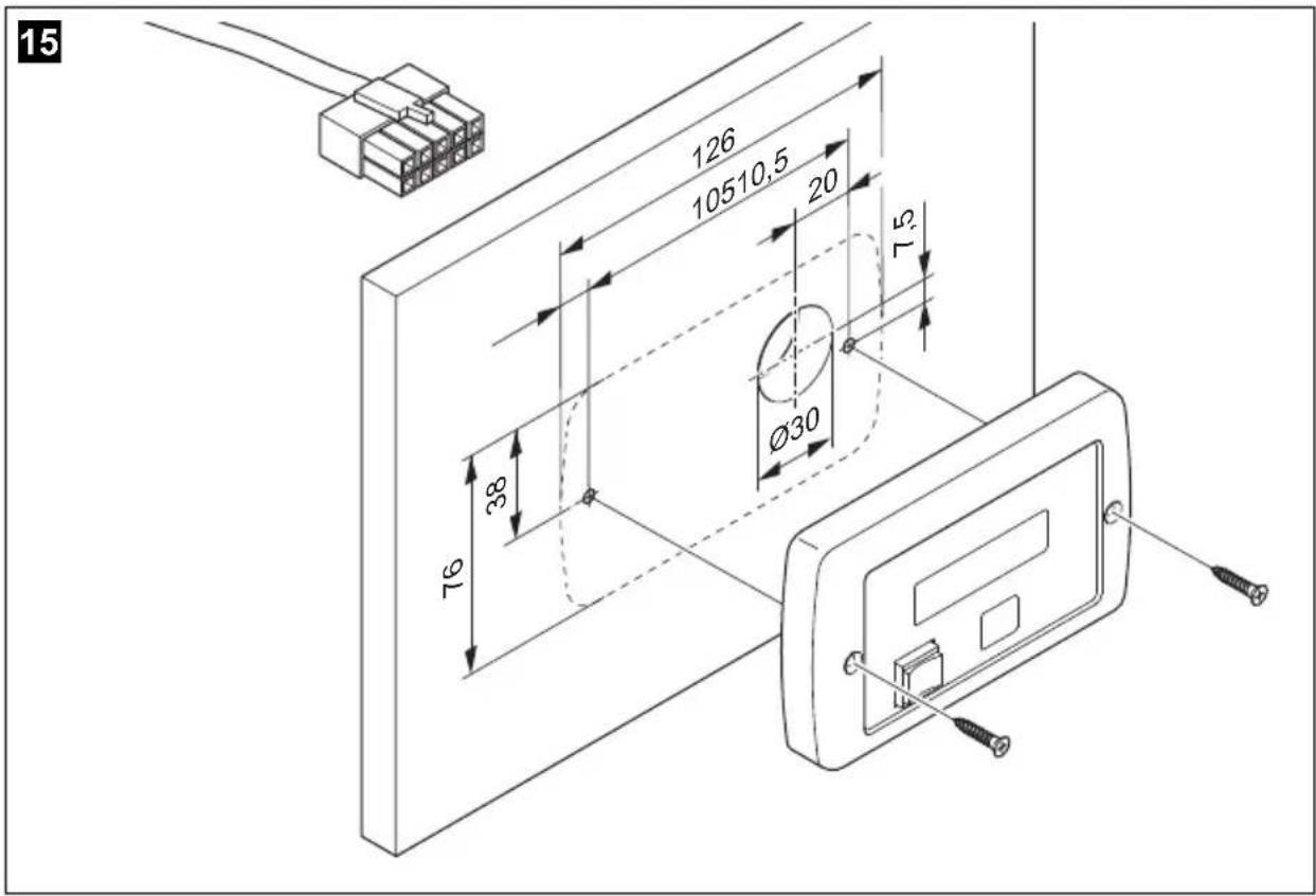
9.7 Mounting the remote control
Please observe the following instructions for the installation location:
- Observe the length of the extension cable from the remote control to the generator.
▶ Drill the holes as shown in fig. 14, page 8.
▶ Insert the plug into the remote control.
▶ Screw on the remote control.
10 Connecting the electrical power to the generator

DANGER! Danger of electrocution
Make sure there is no voltage at electrically operated components before carrying out work on them!

NOTE
Observe the applicable guidelines in the country of the consumer.
10.1 Important notes on the electrical connection
- Only a qualified electrician should connect the generator to the electrical power.
- Check that the voltage specification on the type plate is the same as that of the power supply.
- Any electric connection has to be made with flexible wiring.
- Do not lay the 230 V\~ mains cable and the 12 V== cable together in the same cable duct.
- Do not lay cables which are loose or bent next to electrically conductive material (metal).
- Connect the generator to a power circuit which can supply the necessary current (see chapter "Technical data" on page 33).
- Select the cross-section of the cable as follows:
-230 V: 2.5 mm ^4
- 12V battery charger: 2.5mm ^4
- Battery connection (length < 6 m): 10 mm ^2
- Battery connection (length > 6 m): 16 mm ^2
- Install a manual main switch which can disconnect all the consumers from the generator with the exception of the battery.
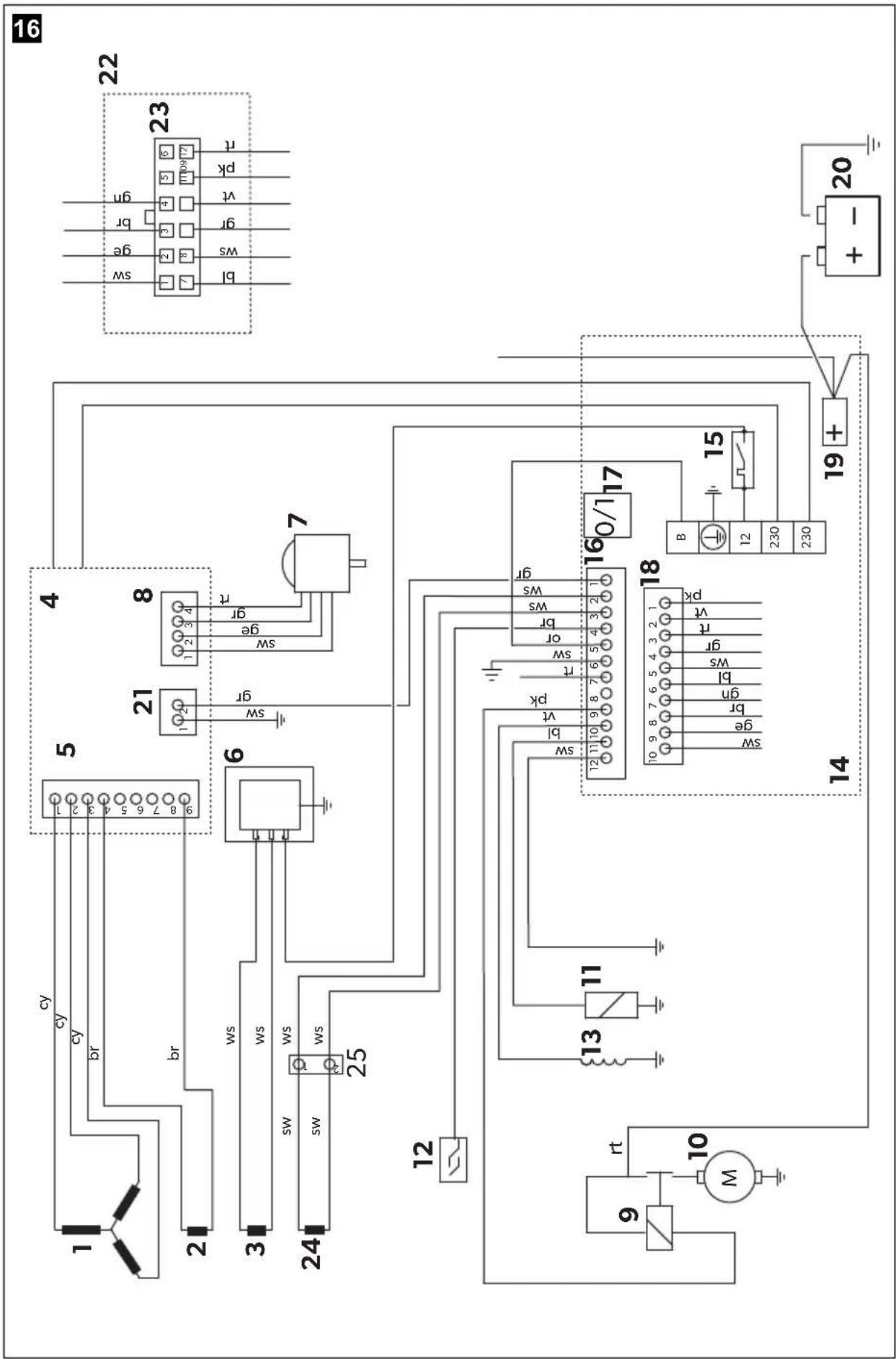
10.2 Circuit diagrams
The complete circuit diagram can be found in fig. 16, page 10.
| Item Description |
| 1 3-phase winding |
| 2 Auxiliary winding |
| 3 Auxiliary winding |
| 4 Inverter |
| 5 9 - p i n p l u g |
| 6 Battery charger |
| 7 Stepper motor |
| 8 4 - p i n p l u g |
| 9 Starter relay |
| 10 Starter motor |
| 11 Electromagnet for cold start |
| 12 Oil level gauge |
| 13 Motor coil |
| 14 Internal control panel |
| 15 Thermal disconnector |
| 16 Interface module |
| 17 Main switch |
| 18 10-pin mini-fit plug |
| 19 Battery positive terminal |
| 20 Battery |
| Item Description |
| 21 2-pin mini-fit plug |
| 22 Remote control |
| 23 12-pin micro-fit plug |
| 24 Auxiliary winding |
| 25 2-pin plug connection |
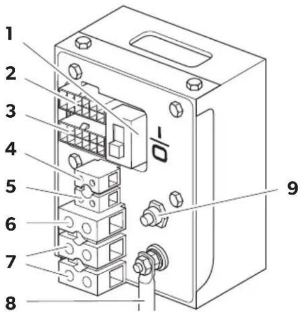
TEC29 EV control panel (fig. 17, page 11)
| Item Description |
| 1 Main switch |
| 2 Motor connection |
| 3 Remote control connection |
| 4 Float connection (petrol tank) |
| 5 12 V battery charger connection |
| 6 Earth |
| 7 230 V connection |
| 8 Battery positive terminal |
| 9 Cut-out switch |
10.3 Connecting 230 V

NOTICE!
- Connect a relay or a switch to the vehicle's electrical system so that the generator is not damaged when the external mains is connected.
- Ensure that the electrical system is set up as follows:
- T N n e t w o r k : The neutral conductor must be linked to the PE conductor on the terminal via a jumper with a minimum diameter of 2.5 mm ^2 . To protect against automatic shutdown, make sure that a safety switch (FI switch, 30 mA) and an in all-pole overcurrent protection (e.g. circuit breaker, 13 A) are installed.
- I T n e t w o r k : Ensure that an insulation monitor and an in all-pole overcurrent protection (e.g. circuit breaker, 13 A) are installed.
- Connect the generator so that it takes priority over the power supply.
▶ Guide the 230 V connection cable through the cable passage in the housing and connect it to the 230 V terminals (fig. 17 7, page 11).
▶ Connect the earth cable to the earth connection (fig. 17 6, page 11).
10.4 Connecting the battery charger
▶ Connect the positive terminal of the battery with the 12 V connection of the battery charger using a cable with a cross-section of 2.5 mm^2 (fig. 17 5, page 11).
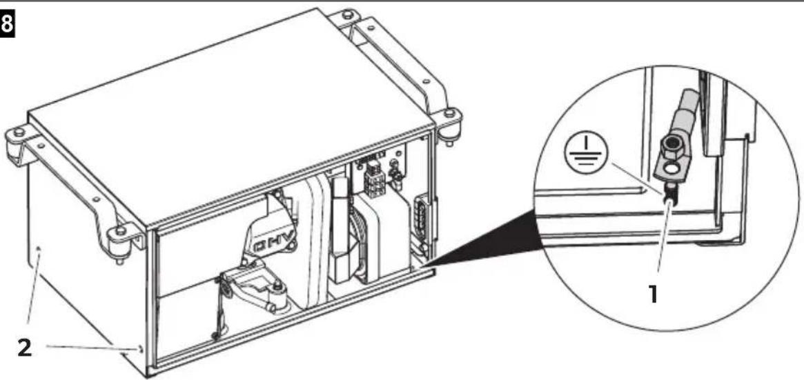
If the battery to be charged is not also the starter battery, connect the negative terminal of the battery to be charged to the generator's earth cable (fig. 18 1, page 11).
10.5 Connecting the starter battery

NOTICE!
The starter battery must have 12 V and a capacity of at least 60 Ah.
▶ Connect the positive terminal of the battery to the positive battery terminal connection using a cable with a cross-section of 10 mm^2 for a length of < 6 m or 16 mm^2 for a length of > 6 m (fig. 17 8, page 11).
- Fit a 100 A fuse in the positive cable near the positive terminal of the starter battery to protect the generator's electrical system.
▶ Connect the negative terminal of the battery using a cable with a suitable cross-section (see above) as follows:
– to the earth connection on the generator (fig. 18 1, page 11) or
– via the inserts at the side of the generator (fig. 18 2, page 11)
▶ Connect the earth connection on the generator to the vehicle chassis.
Remove any paint or rust from the chassis if necessary to ensure good contact.
▶ Protect the connections by applying lubrication.
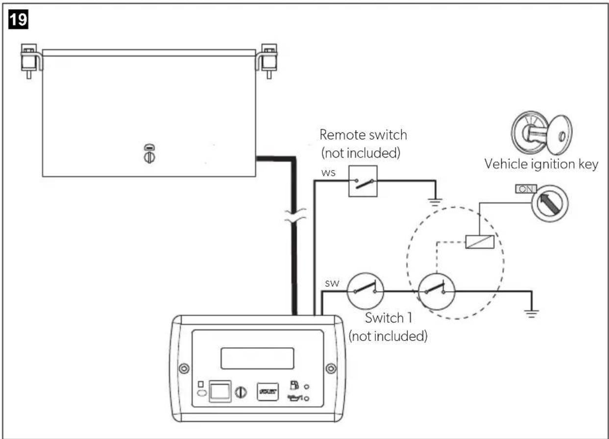
10.6 Configuring the automatic mode

NOTE
- You can only use automatic mode:
- if the vehicle is stationary and the ignition is switched off
- To shorten charging times, an additional charging unit with at least 20 A can be installed between the generator and disconnector switch, especially if batteries with a capacity of more than 60 Ah are used.
- Make sure that one of the two instructions stickers provided is clearly visible affixed next to the external control panel.
- Make sure that the second instructions sticker is affixed to the generators front door.
In automatic mode, the generator switches on automatically and charges the battery if the voltage of the connected battery is too low.
The generator switches off automatically once the battery has been fully charged.
The circuit diagram for the automatic mode can be found in fig. 19, page 12.
▶ Connect the black wire to terminal 6 of the 6-pin plug on the extension cable.
▶ Connect the black wire to switch 1 (not included in the scope of delivery).
▶ Lead the black wire from switch 1 to the ground through a connection managed by the ignition key.
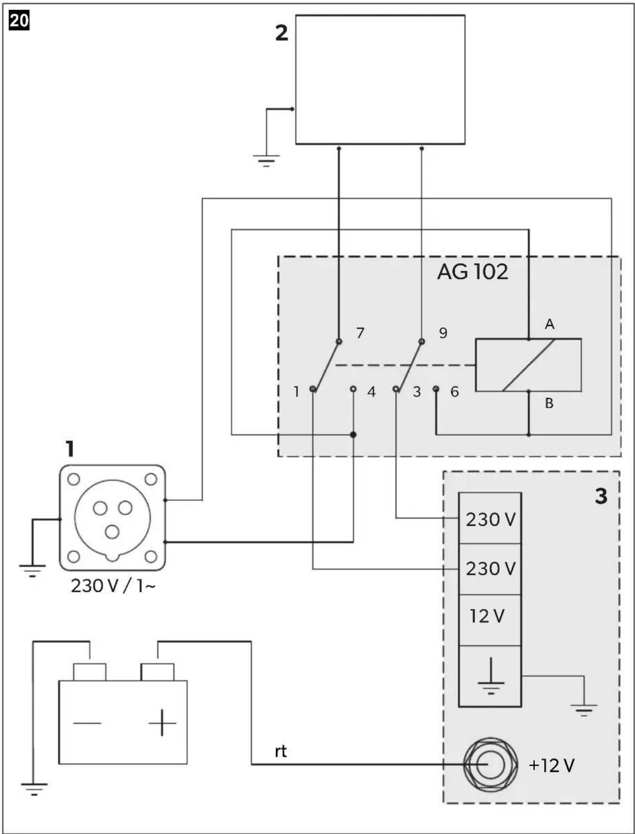
10.7 Creating a priority circuit
You can create a priority circuit using the AG 102 changeover relay whereby the external voltage supply has priority over the generator, see circuit diagram (fig. 20, page 13):
Item Description
1 230 V external voltage supply
2 Vehicle electrical distribution system
3 Connection box
▶ Mount the AG 102 changeover relay in a suitable position.
▶ Disconnect the cable which links the mains input with the circuit breaker in the electrical distribution system of the vehicle so that the connections can be made as shown in the circuit diagram.
▶ Use a flat plug for connecting the cable to the switch.
▶ Connect A with plug-in sleeve 4 and B with plug-in sleeve 6.
▶ Connect the cable from the 230 V connection terminal of the generator to plug-in sleeve 1 and plug-in sleeve 3.
10.8 Connecting the remote control
▶ Connect the remote control to the connection box of the generator using the extension cable provided on the plug for the remote control (fig. 17 3, page 11).
10.9 Connecting the float
▶ Connect the float from the tank to the float connection (fig. 17 4, page 11).
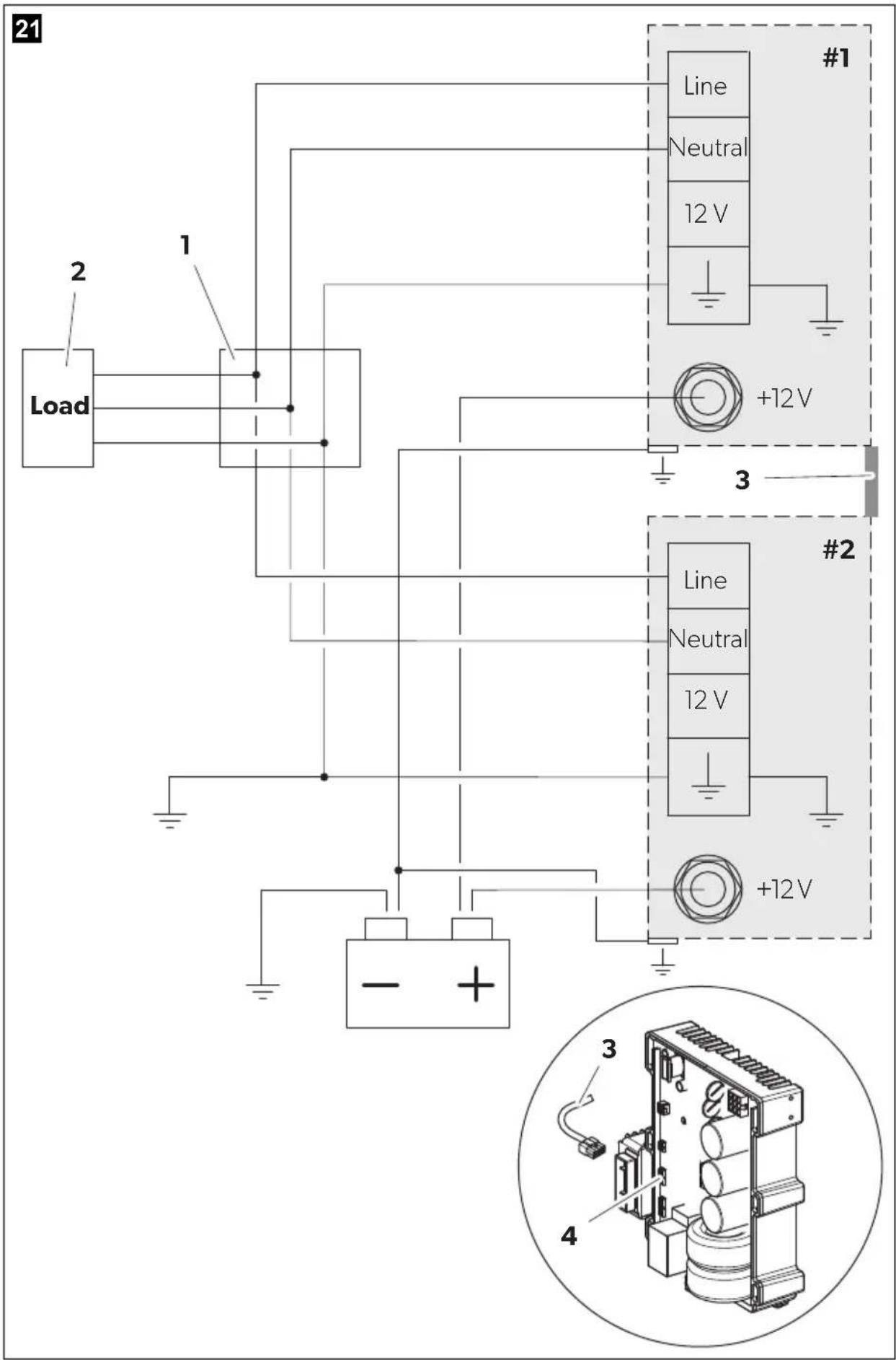
10.10 Connecting two genarators in parallel

NOTE
Use only one starter battery to start both generators.
When connecting the generators, note the following:
- It is not possible to connect more than two generators in parallel.
- To start one generator at a time the starter battery capacity has to be according to the generator manual (minimum capacity: 60 Ah).
To start both generators at the same time you have to double the battery capacity. - The cross section of the battery connection cable for each generator has to be at least:
- 10 ~mm^2 if the total length is less than 6 ~m
- 16 ~mm^2 if the total length is more than 6 ~m

NOTE
- The maximum distance between each generator to the junction box is 15 m.
- The maximum length difference between the output cables of the generators must be 2 m.
Proceed as follows (fig. 21, page 14):
▶ Connect each generator to a junction box (1; not included in the scope of delivery).
The minimum cross section for each generator output cable is 2.5 mm^2 .
▶ Create a single output for the load (2) inside the junction box (1).
The minimum cross section for the parallel output cable is 6 mm^2 .
Connect the battery's negative pole to ground.
▶ Connect the output ground cable to ground.
▶ Connect the change over switch AG 113 (available as accessory) between the junction box and the load.
▶ To properly run the generators in parallel connect the inverters (4) of each generator using the parallel cable (3; available as accessory).
11 Disposal
▶ Place the packaging material in the appropriate recycling waste bins wherever possible.
If you wish to finally dispose of the product, ask your local recycling centre or specialist dealer for details about how to do this in accordance with the applicable disposal regulations.
12 Technical data
| Dometic TEC29 EV | |
| Reference no.: 9102900299 | |
| Rated output voltage: | 230 V~ / 50 Hz |
| Max. constant output (at 300 m altitude and 30 % relative humidity): 2600 W | |
| Derating: | 5 % every 5 °C and 3.5 % every 300 m increasing |
| Battery charger output voltage: 12 V--- | |
| Battery charger max. output current: 10 A | |
| Operating temperature range: -15 °C to +50 °C | |
| Fuel: RON 91 regular grade petrol | |
| Consumption: max. 1.2 l/h | |
| Motor output: 3.6 KW (4.9 PS) at 3600 RPM | |
| Dimensions: see fig. 5, page 5 | |
| Weight: | 44 kg |
8 Description technique
dometic.com/sales-offices


- EN Generator
- DE Generator
- Table of contents
- Explanation of symbols
- DANGER!
- WARNING!
- CAUTION!
- NOTICE!
- NOTE
- Safety and installation instructions
- Please observe the prescribed safety instructions and stipulations from the vehicle manufacturer and service workshops.
- Using the device
- - Fire hazards
- Handling electrical cables
- Target group for this manual
- S c o p e o f d
- A c c e s s o r i
- Intended use
- L a b e l s
- Explanation of pictograms (fig. 22, page 15):
- Technical description
- Installation
- CAUTION! Beware of injury
- Note on installation
- DANGER! Danger of electrocution
- Securing the generator
- Note on installation location
- External installation
- Remove the generator from its chassis
- Install the enclosure on vehicle
- Internal installation
- Install the chassis on vehicle
- Securing the silencer
- Installing the tank and fuel supply line
- Mounting the remote control
- Connecting the electrical power to the generator
- Important notes on the electrical connection
- Circuit diagrams
- Connecting 230 V
- Connecting the battery charger
- Connecting the starter battery
- Configuring the automatic mode
- Creating a priority circuit
- Item Description
- Connecting the remote control
- Connecting the float
- Connecting two genarators in parallel
- Disposal
- Description technique
Brand : DOMETIC
Model : TEC 29
Category : Generator