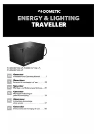
USER MANUAL T 2500H DOMETIC
T2500 H/HG-LP, T4000 H/HG-LP, T5500 H/HG-LP
Generator
EN Installation and Operating Manual 1
Generatore
1.0 Identification 2
1.1 Manufacturer 2
1.2 Definitions 2
1.3 Transport - Handling - storage 2
1.3.1 Storage conditions 2
1.3.2 Weight 2
1.3.3 Overall dimensions 2
1.3.4 Handling 2
2.0 Installation 2
2.1 Authorised personnel 2
2.2 Mounting the generator 3
2.3 Electrical connections 3
2.3.1 Connection of the battery recharger 3
2.3.2 Connection of the starter battery 3
2.3.3 Connection of the remote control panel 3
2.4 Installing the fuel tank 3
Connection to gas canister . 3
3.0 General operation 4
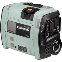
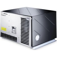
3.1 Description of generator and functioning 4
3.2 Safety advice 4
3.3 Noise levels 4
4.0 Instructions for use 5
4.1 Starting the generator 5
4.2 Stopping the generator 5
4.3 Inherent risks 5
4.4 Improper use 5
4.5 Useful advices 5
4.6 Troubleshooting 5
5.0 Maintenance operations 6
5.1 Nature and frequency of checks 6
5.2 Maintenance operations which do not require qualified technicians 6
5.3 Maintenance operations which require qualified technicians 6
5.3.1 Oil change 7
5.3.2 Air filter maintenance 7
5.3.3 Spark plug maintenance 7
5.3.4 Regulating the voltage 8
6.0 Inactivity and dismantling 8
6. Dismantling 8
7.0 Dealing with fire hazards 8
8.0 Technical data sheet 9
8. Technical specifications 9
8.2 Wiring diagrams 55÷69
© Dometic Italy srl
All rights reserved.
Printed in Italy
Text and graphics by: VEGA - Forli
No part of this publication may be reproduced, copied or transmitted in any form or by any means without prior written permission from DOMETIC ITALY srl.
Figures, descriptions, reference and technical data in this manual are given as mere example and are not binding.
Because of DOMETIC ITALY srl policy of continual product and safety improvement, we reserve the right to make changes at any time without notice.
1.0 IDENTIFICATION
The Identification plate of the machine is affixed outside the plate casing (see fig. 1).
1.1 MANUFACTURER
DOMETIC ITALY srl
Via Virgilio, 3
47122 FORLI' - ITALY
P. IVA 00718330400
1.2 DEFINITIONS
In this handbook, three types of "safety graphics" are used to point out different levels of danger or any other important information:

DANGER
Draws attention to potentially dangerous situations which may cause serious personal injury.

CAUTION
Draws attention to potentially dangerous situations which may cause personal injury or material damage.

IMPORTANT
Draws attention to situations which may cause malfunctioning or damage to the machine.
1.3 TRANSPORT-HANDLING-STORAGE
1.3.1 STORAGE CONDITIONS
The generator is protected against sudden impact by suitable packing consisting of cardboard, polystyrene and a wooden frame support.
The generator should be stored horizontally in a dry and well-ventilated room.
1.3.2 WEIGHT
Gross weight (including packing):
Mod. 2500 Kg 62
Mod. 4000 Kg 114
Mod. 5500 Kg 140
1.3.3 OVERALL DIMENSIONS
See figg. 2, 3, 4 :
| | Model |
| | 2500 | 4000 5500 |
| TYPE "A" INSTALLATION | A mm 470 | 660 700 | |
| B mm 535 740 | | -- |
| C mm 565 | 770 | -- |
| D mm 320 | 475 515 | |
| E mm 315 355 | 510 | |
| F mm 260 310 | | -- |
| G mm | 27 | 62 |
| H mm | -- | -- |
| TYPE "B" INSTALLATION | I mm | 65 | 78 |
| L mm | 65 | 265 |
| M mm 2 | 25 130 | -- |
| N mm | 36 | 17 |
| O mm 5 | 35 740 | 735 |
| P mm | 27 | 62 |
| Q mm 2 | 260 310 | 370 |
| OPENING DIM. | X mm 5 | 90 780 | 770 |
| Y mm 385 | 540 505 | |
| Z mm 3 | 35 380 | 550 |
| Air intake area |
| cm² | 220 | 260 |
1.3.4 HANDLING
The packed generator can be handled by normal means of lifting and transport.
Boxes are fitted with spacers which enable the use of manual fork-lifts.

DANGER
Strictly observe the accident prevention precautions and safety regulations during lifting and transport, and always use machines with a higher maximum capacity than the load to be lifted.
2.0 INSTALLATION
2.1 AUTHORISED PERSONNEL
The generator shall be installed onto the vehicle (caravan, motorhome or special vehicle) by authorised personnel only, namely by skilled technicians or workshops, authorised directly by DOMETIC ITALY srl
If the installation is carried out by non-authorized technicians
or workshops, Domatic Italy srl disclaims any responsibility for the safety and efficient running of the generatore accordind to the M.D. 89/392/EEC

DANGER
The instructions given in sections 2.2 2.3 2.4 are addressed to qualified technicians only.
2.2 MOUNTING THE GENERATOR
Generators mod. 2500 - 4000 are provided with fixing brackets, vibration dampers and petrol filter to be placed on the fuel feed hose to the generator. Brackets allow either suspended type "A" mounting (see fig. 3) or traditional type "B" mounting (see fig. 4).
This is made possible by the supporting frame of the outer casing.
Generator mod. 5500 is provided with brackets for fixing the external seal, brackets for anchoring the unit, vibration dampers, silencer (pos. 29 fig. 16) to be coupled to the exhaust hose delivered as accessory AG 125 (pos. 34 fig. 16), and fuel filter which is standard installed inside the casing (pos. 33 fig. 15). The brackets (pos. 31 fig. 16) which allow to fix the seal (pos. 35 fig. 16) allow to mount the generator complete with seal inside the arranged compartment and to perfectly seal the vehicle side. The exhaust hose can be positioned at will as shown in fig. 16 by rotating the curve inwards to either upper position or lower position. By removing the curve, it is also possible to directly fit the exhaust pipe by crossing the casing on its left-hand side. The prearranged floor must tolerate both the generator mass and the vibrations due to the motion of the vehicle ("TYPE B" mounting).
The type "A" mounting (suspended installation) offers the following advantages: reduced overall dimensions, quick installation, easy access for both ordinary and extraordinary maintenance operations.
Make sure there is enough space around the generator casing for air to pass freely (for cooling). It is also necessary to leave at least 20mm distance between the casing and the surrounding parts.
If the breathing manifold is positioned behind one of the vehicle's wheels, make sure that the tyre is prevented from throwing water into the casing when travelling on wet roads. For the type "A" mounting, use the plate supports provided to ensure that the genset is fixed securely. If type "B" mounting is preferred (traditional installation), a watertight compartment (fig. 2), set towards the vehicle interior and having the dimensions given in section 1.3.3, needs to be prearranged, with exhaust holes and air inlets drilled into the floor and door. In addition, use an exhaust union (fig. 4), supplied as accessory, to be fixed directly onto the generator casing with screws or rivets. In order to prevent the exhaust gas recycling within the compartment, place flameproof sealing around the exhaust union.
2.3 ELECTRICAL CONNECTIONS
For the 230V use a standard cable with cross-section according to table 1 below. Pass it inside the casing via the airlead (pos. 30 fig. 7 and 9) and connect to the terminals (pos. 17/18 fig. 6 and 14). Connect the earth wire to pos. 15. The electrical circuit should have a relay or change-over switch (such as accessory AG102/AG113), so as to prevent any damage to the generator when the camper is connected to an external mains supply (precedence is automatically given to the mains).
| Mod. | Cross-section mm2-230 V | Cross-section mm2-12 V | 6 m | >6 m |
| 2500 | 2.5 | 2.5 | 10 | 16 |
| 4000 | 4 | 2.5 | 10 | 16 |
| 5500 | 4 | 2.5 | 16 | 25 |
| Power cables
Battery recharger | Battery connection
TAB. 1 |
2.3.1 CONNECTION OF BATTERY RECHARGER
Use a wire with minimum cross-section according to table 1 above to connect the terminal (pos. 16 fig. 6 and 14) to the positive lead of the battery to be recharged.
Insert the AG111 voltage regulator, or alternatively a switch, to interrupt recharging when complete.
(See wiring diagrams, pages 55÷ 71
2.3.2 CONNECTION OF STARTER BATTERY
For starting the generator, connect the positive terminal of the vehicle's starter battery to pos. 12 fig. 6 and 14 using a flame-resistant sheathed cable having a cross-section according to table 1 above.
The earth cable should have the same cross-section and be connected from pos. 13 to the vehicle chassis. Make sure that a clean, rust-free contact is made (i.e. rub down surface if painted), and protect with grease.
2.3.3 CONNECTION OF REMOTE CONTROL PANEL
Fix the control panel in desired position inside the vehicle and use the individually-tested AG103 extension cable to connect it to the genset by means of the connector pos. 14 fig. 6 and 14.
2.4 INSTALLING THE FUEL TANK
Install the fuel tank as near as possible to the generator and if possible on the same horizontal level, or up to 30cm below. As well as reducing the length of fuel pipe as much as possible, make sure it is not bent or squashed. Do not put the tank near sources of heat, and make sure that water
cannot infiltrate.
Use LOCTITE 577 to make all connections, so as to prevent fuel leakages.
To connect the fuel tank to the generator, use a 6x13mm rubber-coated tube, of the same type used for the genset and suitable for unleaded petrol. For the extension, use the ties and filter provided. It is advisable to use fuel hose AG118 (accessory) for the connection from tank to refuelling-mouth.

IMPORTANT
Model 5500 does not need fuel tank, since it is standard fitted inside the genset casing.
CONNECTION TO GAS CANISTER

CAUTION
For the LPG genset, withdraw the gas from the upright canister and the vehicle's service regulator and from the upper part, so that gas enters the genset at low pressure and in the gaseous state.
(Working pressure: 30 mbar)
The firm disclaims any responsibility for damages arising from malfunctioning of the generator.
3.1 DESCRIPTION OF GENERATOR AND FUNCTIONING
The generator consists of an endothermic petrol engine connected to an alternator which produces both alternate and direct current.
The unit comes in a soundproof casing made of pressed steel plate and insulated with special deadening materials. Fuel comes to the combustion engine through a pump which is standard fitted on the unit itself.
3.2 SAFETY ADVICE
The unit is housed within a perfectly closed casing. Therefore, there is no danger of accidental contacts with hot or moving parts or wires under voltage.
The door of the unit is fitted with lock and key and should not be left within the reach of children or non-authorised persons.

DANGER
- The unit shall be used only and exclusively with the door closed.
- Keep inflammable substances like petrol, paints, solvents, etc. away from the generator.
- Do not let hot parts of the genset come into contact with inflammable materials.
- Do not fill up with the engine running if the tank is placed close to the generator.
- Do not touch the generator or its connections with wet hands.
- Do not replace the fuses or thermal switches with new ones of higher amperage.
- Any check of the electrical parts shall be made with engine stopped and by authorised technicians only.
The generator is manufactured according to the safety rules given in the Conformity Declaration.
3.3 NOISE LEVELS
The generator has been submitted to a noise emission test at a qualified ISTEDIL lab, where all the necessary tests were carried out and EC Certificate No.1-225/92 issued, stating following results:
Measured according to: EC DIRECTIVE 84/536 NOISE LEVEL:
Mod. 2500 LwA 85
Mod. 4000 LwA 87
Mod. 5500 LwA 87
4.0 INSTRUCTIONS FOR USE
4.1 STARTING THE GENERATOR
Normally the vehicle's 12V battery is used to start the genset.
First press the red button (pos. 27 fig. 5) on the control pane into the "l" position.
To start the genset from cold, press and hold down the green START button (pos. 25 fig. 5) together with the white CHOKE button (pos. 26 fig. 5) for max. 5 seconds.
4.4 IMPROPER USE

DANGER
The generator is to be installed by qualified technicians only, according to the manufacturer's instructions.
The generator is to be used only and exclusively for producing current for mobile vehicles, fitted with a standard electrical circuit in keeping with the power supplied by the generator.
4.5 USEFUL ADVICES
To use the genset at best, we remember you that little, but prolonged, overloads may cut off thermal switches pos. 10 and 11 shown in fig. 6 and 14.
During running-in, it is advisable that the new engine is not subjected to loads exceeding its nominal load by 70% , at least during the first 50 running hours.

CAUTION
Do not make prolonged or repeated (more than 5 consecutive) attempts to start the genset, as this may damage the starter motor.
To start the genset when already warmed-up, or during the summer, when the outside temperature is high, press the green "START" button (pos. 25 fig. 5) only.
In an emergency the genset can be started manually using the pull-cord handle (pos. 4 fig. 8 and 15) and holding the choke magnet (pos. 36 fig. 8 and 15) shut with one hand if the engine is cold.
The green LED on the control panel ((pos. 23 fig. 5) indicates that the genset is running correctly.
4.2 STOPPING THE GENERATOR
Push the red "STOP" button (pos. 27 fig. 5) on control panel into the "0" position. Alternatively use the safety switch on the genset itself (pos. 7 fig. and 14) for models 2500 - 4000 - 5500.
4.3 INHERENT RISKS

DANGER
The generator is fitted with a combustion engine, and therefore runs on highly inflammable fuelstuffs.
Exhaust gases are conveyed under the casing and, although mixed with cooling air, they are inevitably hot.
Do not touch the parts of the casing close to the exhaust and do not place your hands or other objects within the duct.
4.6 TROUBLESHOOTING
We have listed below some problems which may occur, along with their respective causes and possible solutions. In the case of problems which are not listed below, please seek advice from an authorised after-sales service centre.
Causes and Solutions:
1.1 Check that the red switch (pos. 27 fig. 5) is in the "l" position.
1.2 Electrical wires loose or disconnected. (Have checked by qualified personnel).
1.3 No power supplied to starter-motor. (Have checked by qualified personnel).
1.4 Earth wire of generator disconnected. (Have checked by qualified personnel).
2 The starter-motor turns, but the generator does not start.
Causes and Solutions:
2.1 No fuel: check.
2.2 No oil in engine. Check if the red warning light (pos. 6 fig. 5) on the control board blinks during the starting phase. Check the oil level and top up if necessary (see Maintenance section).
2.3 The safety switch (pos. 7 fig. 6 and 14) is in the "0" position. Check and press in the "I" position.
2.4 Check that the engine's spark-plug nipple is fully inserted.
2.5 No current to the spark plug. (Have checked by qualified personnel).
2.6 No fuel getting to the carburettor. (Have checked by qualified personnel).
3 The generator tends to stall.
Causes and Solutions:
3.1 No more fuel left in the tank: refill.
3.2 Low oil level.
Check and top up.
(See Maintenance section).
3.3 Air filter is dirty.
(Have checked by qualified personnel).
4 The generator does not produce current
Causes and Solutions:
4.1 Thermal switch off.
Set it to 'on' by pushing the switches (pos. 10 fig. 6 and 14) for 230V A.C., (pos. 11 fig. 6 and 14) for 12V D.C.
4.2 Condenser (pos. 19 fig. 8) damaged.
(Have checked by qualified personnel).
4.3 Diode rectifier (pos. 21 fig. 8) damaged.
In this case, only the 12V D.C. and the green LED on the control board are not working.
(Have checked by qualified personnel).
4.4 Rotor diodes damaged.
(Have checked by qualified personnel).
4.5 Frequency too low.
(Have checked by qualified personnel).
5 The unloaded current produced oscillates.
Causes and Solutions:
5.1 Too much oil in the engine: check.
5.2 Defective carburation.
Have the carburettor cleaned by qualified personnel.
Use only genuine spare parts. The generator may get damaged if other than genuine parts having a different quality standard are used.
To make sure that the generator keeps working to maximum efficiency, it is essential that it is properly and regularly maintained. Additionally, a proper maintenance grants the generator a longer lifetime.

DANGER
Before carrying out any check or maintenance operation on the genset, rotate safety switch (pos. 7 fig. 6 and 14) to "0" position to prevent any accidental startings of the unit.
5.1 NATURE AND FREQUENCY OF CHECKS
| ORDINARY MAINTENANCE INTERVAL carry out at the intervals or after the running hours given in the table, depending on which occurs first. | Every use | First month or 20 hours | Every 3 months or 50 hours | Every 6 months or 100 hours | Every year or 300 hours |
| Engine oil Inspection Change | ▲ | | | | |
| Air filter Clean ing | | | (1)▲(2) | | |
| Spark plug Inspection-Cleaning | | | | ▲(2) | |
| Valve adjustment Check - adjust | | | | | ▲(2) |
| Fuel filter and tank Cleaning | | | | | ▲(2) |
| R.p.m. or frequency Adjust | | ▲(2) | | | ▲(2) |
| Suspension points for vibration dampers Inspection | | | | | ▲(2) |
| Fuel hoses Check (replace, if necessary) | Every two years (2) |
REMARK (1):Clean more frequently when used in dusty areas
(2): Get this work done by a specialist only
5.2 MAINTENANCE OPERATIONS WHICH DO NOT REQUIRE QUALIFIED TECHNICIANS
To carry out these operations, the generator door first needs to be opened. Therefore, the following measures should be taken:
1) The generator must be stopped with all parts cold.
2) Let the unit cool.
3) Set the safety switch to the "0" position.
N.B.Remember to set it to the "I" position again aftercheck!
OIL LEVEL CHECK
1) Remove the oil filling cap (pos. 9 fig. 8) and clean the dipstick.
2) Re-introduce the dipstick by screwing it in fully.
3) Remove the dipstick and check that the oil level is between min. and max. levels.
If not, top up with the recommended oil.
4) Refit the cap.

IMPORTANT
All checks should be carried out with the genset horizontal.
5.3 MAINTENANCE OPERATIONS WHICH REQUIRE QUALIFIED TECHNICIANS
For some maintenance operations you need to slide the unit out on its runners (pos. 28 fig. 7 and 15) after first loosening the fixing screws.
5.3.1 OIL CHANGE
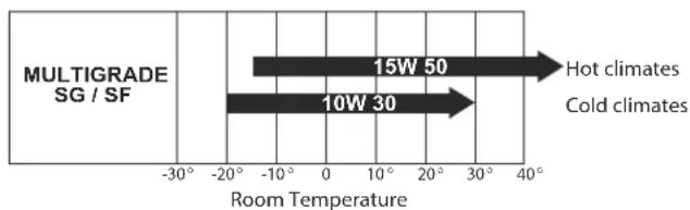
Use detergent oil for four-stroke engines, class API SG or SF (indicated on the oil can) with SAE viscosity suitable for the climate (see table).
To allow the oil to drain out easier, run the engine for about 3÷ 5 minutes. Then discharge the oil when the engine is still warm so that the emptying is quicker and more complete via the drainage hose (pos. 2 fig. 8 and 15) by removing the drain cap (pos. 8 fig. 8 and 15).
Top up with oil of the recommended type via the filling cap (pos. 9 fig. 8).
Table 2 shows the amount of oil in the oil pan.
TAB. 2
| Mod. Liters | |
| 2500 0.6 | |
| 4000 1.1 | |
| 5500 1.1 | |
5.3.2 AIR FILTER MAINTENANCE

IMPORTANT
A dirty air filter reduces the air flow to the carburettor. To keep the carburettor working properly, check it often. Check more frequently if the engine is used in dusty areas.

DANGER
Never use diesel oil or solvents with a low evaporation point for cleaning the air filter, since this may lead to danger of flames or explosion.
Never let the engine run without the air filter. It would get damaged in a short space of time.
- Carefully check both cartridges. Replace them if there are holes or tears
- Sponge cartridge: wash it with a neutral detergent solution and rinse carefully. Let the cartridge dry completely, then soak it in clean engine oil and wring out the excess.
- Paper cartridge: smoothly beat it several times on a hard surface to remove any dirt, or blow compressed air through the filter from inside to out. Do not brush the dirt: this operation would just push it into the fibres. If the paper cartridge is too dirty, replace it.
5.3.3 SPARK PLUG MAINTENANCE

DANGER
Warm oil may burn you.
- Running the engine with a poor amount of oil can seriously damage the engine itself.
- Check the oil level when engine is stopped.

IMPORTANT
Used oils must never be poured on the ground. They shall be collected and consigned to qualified companies for the disposal in accordance with any local regulations.
RECOMMENDED SPARK PLUG:
Mod. 2500/4000/5500
BP6ES,BPR6ES
NGK
W20EP-U, W20EPR-U
ND
Never use a spark plug with a different thermal degree.
- Remove the spark plug nipple (pos. 1 fig. 8) and use a suitable wrench to remove the spark plug.
- Visually check the spark plug. If it is worn or if the insulator is broken or chipped, replace it. Clean the spark plug with an iron brush if it is to be used again.
- Measure the electrode distance by means of a thickness gauge.
The distance should be 0.7 - 0.8mm
Adjust, if necessary, by bending the side electrode.
- Check that the spark plug washer is in good condition and screw it manually to prevent it being set at an angle.
- Once mounted, tighten the spark plug using a wrench with the right driving torque.

IMPORTANT
When mounting a new spark plug, tighten it a half-turn after it has compressed the washer. When re-using the same spark plug, tighten it 1/8-1/4 turn after the washer compression.

CAUTION
The spark plug should be tightened carefully. A loose spark plug can get very hot and damage the engine.
5.3.4 REGULATING THE VOLTAGE
This regulation should be carried out with the engine warm and the generator running without a load.
Check the generator voltage using a tester or voltmeter connected to the vehicle's 230V socket or to the terminals (pos. 17-18 fig. 6 and 14) of the generator terminal board.
The voltage should be between 230 and 240 Volts.
If these values are not obtained, adjust the current regulation screw (pos. 32 fig. 10 and 15) until they are.
Rotate clockwise to increase the voltage.
Rotate anticlockwise to decrease both r.p.m. und voltage.
6.00 INACTIVITY AND DISMANTLING
6.01 DISMANTLING
If the unit must be dismantled, get the work done by authorised workshops.
7.0 DEALING WITH FIRE HAZARDS
In case of fire, do not open the generator casing and use type-approved fire-extinguishers.
8.0 TECHNICAL DATA
8.1 TECHNICAL SPECIFICATIONS
| ENGINE 2500H 4000H 5500H | | | |
| Type | Single-cylinder, four-stroke, overhead valves |
| Honda model GX 160 GX 270 GX 390 Displacement cm 3 Stroke x bore mm 68x45 77x58 88x64 Consumption g kW/h Fuel Starter system Spark plug Engine-oil sump capacity litre Frequency regulator | 163 270 389 230 235 Lead-free p etrol Electronic NGK 0.6 Automatic with centrifugal masses |
| ALTERNATOR | 2500H | 4000H | 5500H |
| Type | Synchronous, single-phase, self-regulated, self-energized, two-pole, brushless |
| Peak max. power W | 2200 | 3800 | 5300 |
| For continuous utilization W | 2000 | 3500 | 4500 |
| Voltage/frequency D.C. power Rotor insulation class H Stator insulation class F | 12V 10A H F | 12V 10A H F | 2 30V 50Hz 12V 10A H F |
| Cooling | Centrifugal f an |
| GENERATOR | 2500H 4000H 5500H |
| Total weight Kg Overall dimensions (L×W×H) mm Ignition Fuel pump Remote control | 50 530×385×290 Electric/man. Vacuum Separate control board with: push-button starter push-button choke stop switch low fuel LED running LED low oil LED (automatic stop) hour meter | 132 700×520×510 |
INDICE GENERALE
GB 1÷9
1 10÷18
D 19÷27
NL 28÷36
F 37÷45
SP 46÷54
INDICE
DescrizionePagina
Domatic Italy srl
3.3 Luchtfilter is vies.
W20EP-U, W20EPR-U ND
1.0 Identification 38
1.1 Maison de Construction 38
1.2 D'efinitions 38
1.3 Transport - Manutention - Stockage 38
1.3.1 Conditions de stockage 38
1.3.2 Poids 38
1.3.3 Encombrement 38
1.3.4 Manutention 38
1.3 TRANSPORT - MANUTENTION - STOCKAGE
1.3.1 CONDITIONS DE STOCKAGE
La tension debe resultar 230÷ 240 volts.
Dometic Australia Pty. Ltd.
1 John Duncan Court
Varsity Lakes QLD 4227
1800212121
+61755076001
Mail: sales@dometic-waeco.com.au
AUSTRIA
Dometic Austria GmbH
Neudorferstraße 108
A-2353 Guntramsdon
+432236908070
+43223690807060
Mail: info@dometic.at
BENELUX
Domatic Branch Office Belgium
Zincst
B-1500 Haile
+3223598040
+3223598050
Mail: info@dometic.be
BRAZIL
Dometic DO Brasil LTDA
Avenida Paulista 1754, conj. 111
SP 01310-920 Sao Paulo
+551132513352
+551132513362
Domatic Group Asia Pacific
Suiles 2207-11-22/F-Tou
The Gateway 25 Canton Road
Tsim Sha Tsui - Kowloon
+85224611386
+8522466553
Mail: info@waeco.com.hk
HUNGARY
Dometic Zrt. Sales Office
Kerekgyartou.5
H-1147 Budapest
+3614684400
+3614684401
Dometic Italy S.r.l.
Via Virgilio, 3
147122Forli(FC)
+390543754901
+390543754983
Mail: vendite@dornetic.it
JAPAN
Dometic KK
Maekawa-Shibaura,Bldg.2
2-13-9 Shibaura Minato-ku
Tokyo 108-0023
+81354453333
+81354453339
Mail: info@dometic.jp
MEXICO
Domatic Mx, S. de R. L. de C. V.
Circuito Médicos No. 6 Local 1
Colonia Ciudad Satélite
CP 53100 Naucalpan de Juarez
Estado de Mexico
+525553744108
+525553934683
Mail: info@domelic.com.mx
NETHERLANDS
Domatic Benelux B.V.
Ecustraat 3
NL-4879 NP Etten-Leur
+31765029000
+31765029019
Mail: info@dometic.nl
NEW ZEALAND
Dometic New Zealand Ltd.
Unite E, The Gate
373 Neilson Street
Penrose 1, Auckland
+6496221490
+6496221573
Mail: customerservices@dometic.co.nz
NORWAY
Dometic Norway AS
Osteroyveien 46
N-3232 Sandefjord
+4733428450
+4733428459
Mail: firmapost@dometic.no
POLAND
Dometic Poland Sp. z o.o.
Ul. Puławska 435A
PL-02-801 Warszawa
+48224143200
+4822414320
Mail: info@dometic.pl
PORTUGAL
Dometic Spain, S.L.
Komsomolskaya square 6-1
RU-107140 Moscow
+74957807939
+74959165653
Mail: info@domestic.ru
SINGAPORE
Dometic Pte Ltd
18 Boon Lay Way 06-140 Trade Hub 21
Singapore 609966
密 +6567953177
+6568626620
Mail:domatic@dometic.com.sg
SLOVAKIA
Dometic Slovakia s.r.o. Sales Office Bratislava
Nadrażna 34/A
900 28 Ivanka pri Dunaji
/+421245529680
Mail: bratislava@dometic.com
SOUTH AFRICA
Dometic (Pty) Ltd.
Regional Office
South Africa & Sub-Saharan Africa
2 Avalon Road
West Lake View Ext 11
Modderfontein 1645
Johannesburg
+27114504978
+27114504976
Mail: info@dometic.co.za
SPAIN
Dometic Spain S.L.
Avda. Sierra del Guadarrama, 16
E-28691 Villanueva de la Canada
Madrid
+34902111042
+34900100245
Mail: info@dometic.es
SWEDEN
Dometic Scandinavia AB
Gustaf Melins gata 7
Dometic Switzerland AG
Riedackerstrasse 7a
CH-8153 Rumiat
+41448187171
+41448187191
Mail: info@dometic.ch
UNITED ARAB EMIRATES
Dometic Middle East FZCO
P.O.Box17860
S-D 6, Jebel Ali Freezone
Dubai
+97148833858
+97148833868
Mail: info@dometic.ae
UNITED KINGDOM
Dometic UK Ltd.
Dometic House, The Brewery
Blandford St. Mary
DorsetDT119LS
+443446260133
+443446260143
Mail: customerservices@dometic.co.uk
USA
Dometic RV Division
1120 North Main Street
Elkhart, IN 46515
+1574-264-2131