USER MANUAL TEC 60EV DOMETIC
natural_image
Exterior view of a black industrial electronic device with ventilation grilles and a central control unit (no visible text or symbols)
TEC60EV
EN Generator Operating manual....8
natural_image
Technical line drawing of an internal device housing with visible wiring and components (no text or symbols)
Please read this instruction manual carefully before first use, and store it in a safe place. If you pass on the product to another person, hand over this instruction manual along with it.
Table of contents
1 Explanation of symbols....8
2 Safety instructions....9
3 Target group for this manual....11
4 Scope of delivery ..... 11
5 Accessories....12
6 Intended use....12
7 Technical description ..... 12
8 Operating the generator ....14
9 Cleaning the generator....19
10 Servicing the generator .....19
11 Troubleshooting 24
12 Warranty 25
13 Disposal.... 25
14 Technical data.... 26
1 Explanation of symbols

WARNING!
Safety instruction: Indicates a hazardous situation that, if not avoided, could result in death or serious injury.

CAUTION!
Safety instruction: Indicates a hazardous situation that, if not avoided, could result in minor or moderate injury.

NOTICE!
Indicates a situation that, if not avoided, can result in property damage.

NOTE
Supplementary information for operating the product.
2 Safety instructions
Please observe the prescribed safety instructions and stipulations from the vehicle manufacturer and service workshops.
The manufacturer accepts no liability for damage in the following cases:
- Damage to the product resulting from mechanical influences and incorrect connection voltage
• Alterations to the product without express permission from the manufacturer
- Use for purposes other than those described in the operating manual
In particular, the manufacturer will not be liable for any consequential damage, especially consequential damage caused by failure of the generator.
Note the following basic safety information when using electrical devices to protect against:
- Electric shock
- Fire hazards
- Injury
2.1 General safety

WARNING! Failure to obey these warnings could result in death or serious injury.
Health hazard
- Only use the device as intended.
-
Do not make any alterations or conversions to the device.
-
Installation, maintenance and repairs of the generator may only be carried out by qualified personnel who are familiar with the risks involved when handling generators as well as the relevant regulations. Inadequate repairs may cause serious hazards. For repair service, please contact the manufacturer's branch office in your country (see back page).
- People (including children) whose physical, sensory or mental capacities prevent them from using this device safely may not be allowed to operate it without the supervision of a responsible adult.
Risk of asphyxiation
- Exhaust fumes contain carbon monoxide which is a highly toxic, odourless and colourless gas. Do not inhale any exhaust fumes. Do not leave the generator motor running in a closed garage or in a room without windows.
Electrical shock
• Electrical devices are not toys
Keep electrical devices out of reach of children or infirm persons. Do not allow them to use electrical devices without supervision.

CAUTION! Failure to obey these cautions could result in minor or moderate injury.
Health hazard
- The generator may only be used with the flap closed.
Fire hazard
- Remove all flammable materials such as petrol, paints, solvents, etc., from the vicinity of the generator.
- Ensure that hot parts of the generator do not come in contact with any flammable materials.
- Only refuel the generator when it is switched off and in a well-ventilated area. Petrol and liquid gas are highly flammable and can explode.
- Do not refuel the generator when the vehicle engine is running if the tank is in the vicinity of the generator.
- If petrol is spilled, wipe it up properly and wait until the fumes have cleared before turning on the engine.
Electrical shock
- Do not touch the generator and the cables with wet hands.
- Replace the fuses or thermo switch using only those with the same technical data.
- Only operate the device if you are certain that the housing and the cables are undamaged.

NOTICE! Damage hazard
- Do not fill up the tank too full. Petrol must not be allowed to fill up to the neck of the tank. Check the lid is on properly.
- If a welding operation has been done on the vehicle disconnect all generator cables, otherwise the electronics may be damaged.
2.2 Operating the device safely

WARNING! Failure to obey these warnings could result in death or serious injury.
Electrical shock
• Always disconnect the power supply when working on the device.
3 Target group for this manual
This operating manual is for the user of the generator.
4 S c o p e o f d
Designation
| TEC60EV generator |
| Changeover relay for making priority circuits |
| Control panel |
| Silencer |
| Exhaust pipe |
| Mounting material for silencer |
| Connection cables |
| Mounting material |
| Installation manual |
| Operating manual |
5 A c c e s s o r i
Available as accessories (not included in the scope of delivery):
Part designation Reference no.
PR 250133, external sealing kit 9600025375
6 Intended use
The generator TEC 60 EV is designed for use in motor homes, camper vans and vehicles for commercial use.
The generator is not suitable for installation in water vessels.
The generator produces a pure sine wave voltage of 230 V/50 Hz which can be connected to the consumer with a total continuous load of 6200 W.
The power quality is also suitable for sensitive consumers (such as PCs).
The generator can charge a 12 V battery.
7 Technical description
The generator consists of the following main parts (fig. 1, page 3):
• Power generator with permanent magnets (1)
- Combustion engine (2)
- Connection box (3)
- Inverter (4)
- Control panel (5)
The combustion engine (2) drives the power generator connected to it (1), which in turn generates AC voltage.
The internal inverter (4) transforms this AC voltage into a stable voltage of 230 V and 50 Hz.
The terminals and the main switch are installed in the connection box (3) located behind the door.
The control panel is used to operate the device (5).
The generator has an integrated battery charger for charging the connected battery.
Control elements in the connection box
The connection box is located on the generator behind the cover.
| No. in fig. 2, Description page 3 |
| 1 Main switch Switches the generator to standby or no function. |
| 2 Thermal protection of the inverter | Activates if the inverter overheats (see chapter “Display messages” on page 16) |
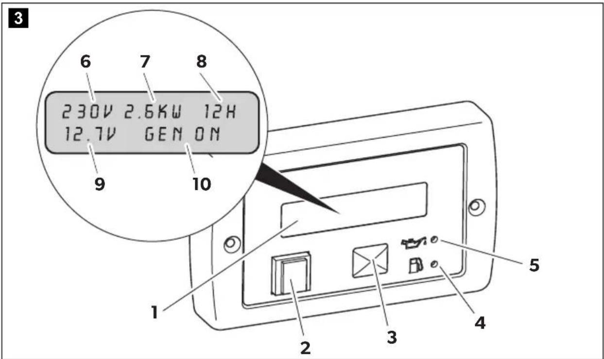
Control elements in the control panel
The control panel is installed in the vehicle interior.
| No. in fig. 3, Description page 4 |
| 1 Display Shows the status reports. |
| 2 | On/Off switch ⏻ | Switches the control panel on and off if the main switch is at “1” or “1”.Stops the generator in emergency. |
| 3 Grey button START/STOP Starts/stops the generator if the control panel is switched on and the main switch is at “1” or “1”. |
| 4 Petrol gauge Lights up if the petrol goes into reserve. |
| 5 Oil gauge Lights up if the oil level is too low in the engine. |
Displays

Description
6 AC supply Actual voltage output
7 Constant output Current capacity of connected consumer
8 Operating hours Time the generator is in operation
9 DC voltage Battery charging voltage
10 Messages Status reports of the generator (see chapter "Display messages" on page 16)
8 Operating the generator

NOTICE! Damage hazard
Do not run the generator over 70% of the maximum constant output for the first 50 operating hours (run-in phase).

NOTE
By doing this you can prolong the service life of the generator and optimise its output:
run the generator at a maximum of approx. 75 % of the maximum continuous load after the run-in phase.
8.1 Basic notes on operation

CAUTION! Beware of injury
Do not insert your fingers or objects into the air nozzles or the intake grille.
Please note the following basic information:
- Always check the oil level before use (chapter "Checking the oil level" on page 18).
- Even small overloads in the long-run will cause the generator to stop.
-
Leave the generator running for a few minutes after use without any consumers before stopping it.
-
Abrupt braking, accelerating and driving round bends in the vehicle can cause problems in the generator's pump system and lead to unwanted shutdown.
- If you are not using your generator for a longer period of time, start it up at least every 30 days and leave it running for 15 minutes or more.
8.2 Switching the generator to standby or no function
The generator can be switched to standby or no function with the main switch (fig. 2 1, page 3) in the connection box.
8.3 Switching the control panel on and off
This switch on the control panel (fig. 3 2, page 4) is for switching the control panel on and off.
▶Switch the control panel on with the on/off switch.
√The display shows: GEN OFF.
The display switches off automatically after 5 minutes if the start button is not touched within this time.
Press the start button to switch on the display again.
√The generator can now be started.
8.4 Starting the generator
The generator can only be started if it is in standby and the control panel is switched on.
▶ Start up the generator with the grey button "START/STOP" (fig. 3 3, page 4).
8.5 Stopping the generator
▶ Stop the generator with the grey button "START/STOP" (fig. 3 3, page 4).
√ The inverter shuts down immediately. The engine runs for 30 seconds to cool down, then the engine stops too.

NOTICE! Damage hazard
Always stop the generator with the grey button "START/STOP" to avoid engine damages. The turn off procedure with the red button has to be used only for emergency.
8.6 Display messages
| Display messageDescription | Generator behaviour Measures |
| LOW BATTERYThe battery voltage has fallen below the minimum value for starting up (9 V). | The generator does not start. Charge the battery. |
| CHECK OIL LEVEL | The generator continues to run. Fill up with oil (see chapter “Checking the oil level” on page 18). |
| OIL CHANGEThe number of prescribed operating hours has been reached for changing the engine oil. | The generator continues to run. Change the oil (see chapter “Changing the oil” on page 21), then confirm the message by pressing and holding down the button START/STOP. Restart the generator by again pressing and holding down the button START/STOP. |
| NO FUELThe petrol in the tank is in reserve. | The generator continues to run. Refuel. |
| OIL ALERTInsufficient engine oil. | The generator stops. Fill up with oil (see chapter “Checking the oil level” on page 18). |
| GENERATOR ALERT!General alarm messageExample: The control ring on the throttle valve of the carburettor (stepper motor) is faulty. | The generator stops. Check the system by referring to the troubleshooting table.If the problem persists, contact the manufacturer's branch office in your country (see back page). |
| OVERLOAD!The consumers generate an overload at the output. | The inverter switches off, therefore no voltage is supplied but the engine carries on running until it goes off. | Reduce the connected load and start the generator again. |
| SHORT CIRCUITThe consumers cause a short circuit at the output. | The inverter switches off, therefore no voltage is supplied but the engine carries on running until it goes off. | Check the connected consumers then start the generator again. |
| OVER TEMPERATUREOverheating | The inverter switches off so no voltage is supplied to cool the generator, but the engine car-ries on running. | Leave the engine to cool down for a few minutes then start the generator again. |
| LOW POWER ENGINEThe inverter supply voltage has dropped. | The generator stops. Reduce the connected load and start the generator again. |
| OVERSPEEDRPM too high | The generator stops. Press the button START/STOP to restart the generator. If the problem persists, contact the manufacturer's branch office in your country (see back page). |
| START FAILEDExample: No fuel, cold temperature, spark plug to be replaced, dirty air filter | The generator is switched off. Press the start button to restart the generator. |
| GEN CALMessage appears when the generator is started up; it shows the calibration phase which takes place before each start-up. The generator does not supply any voltage. | The generator is running but does not supply any voltage. | Wait a moment. |
| GEN WAITMessage appears while you are waiting for the generator to start again. | The generator is switched off. Wait until the message has disappeared then attempt ignition again. |
| GEN ONThe generator is operating normally. | Normal mode – |
| GEN OFF | The generator is idle and can be – started. |
| GEN STOP | The generator is stopped. Wait a moment. |
| WAIT COOLING | The engine is running without load to cool down the system. | Wait a moment. |
| INVERTER LOST COMM | The generator stops. Check the system by referring to the troubleshooting table.If the problem persists, contact the manufacturer's branch office in your country (see back page). |
| Display messageDescription | Generator behaviour Measures |
| ENGINE LOST COMM | The generator stops. Check the system by referring tothe troubleshooting table.If the problem persists, contactthe manufacturer's branch officein your country (see back page). |
| INVERTER FAILED | The generator stops. Contact the manufacturer'sbranch office in your country (see back page). |
| ENG. PARAM. ERROR | The generator stops. Contact the manufacturer'sbranch office in your country (see back page). |
| INV. PARAM. ERROR | The generator stops. Contact the manufacturer'sbranch office in your country (see back page). |
| SOFTWARE ERROR | The generator stops. Contact the manufacturer'sbranch office in your country (see back page). |
8.7 Checking the oil level

CAUTION! Risk of injury
Hot oil can cause burns.
Only check the oil level when the generator is switched off.

NOTE
The generator must be level.
Always check the oil level before use. To do this, proceed as follows:
▶Open the generator flap.
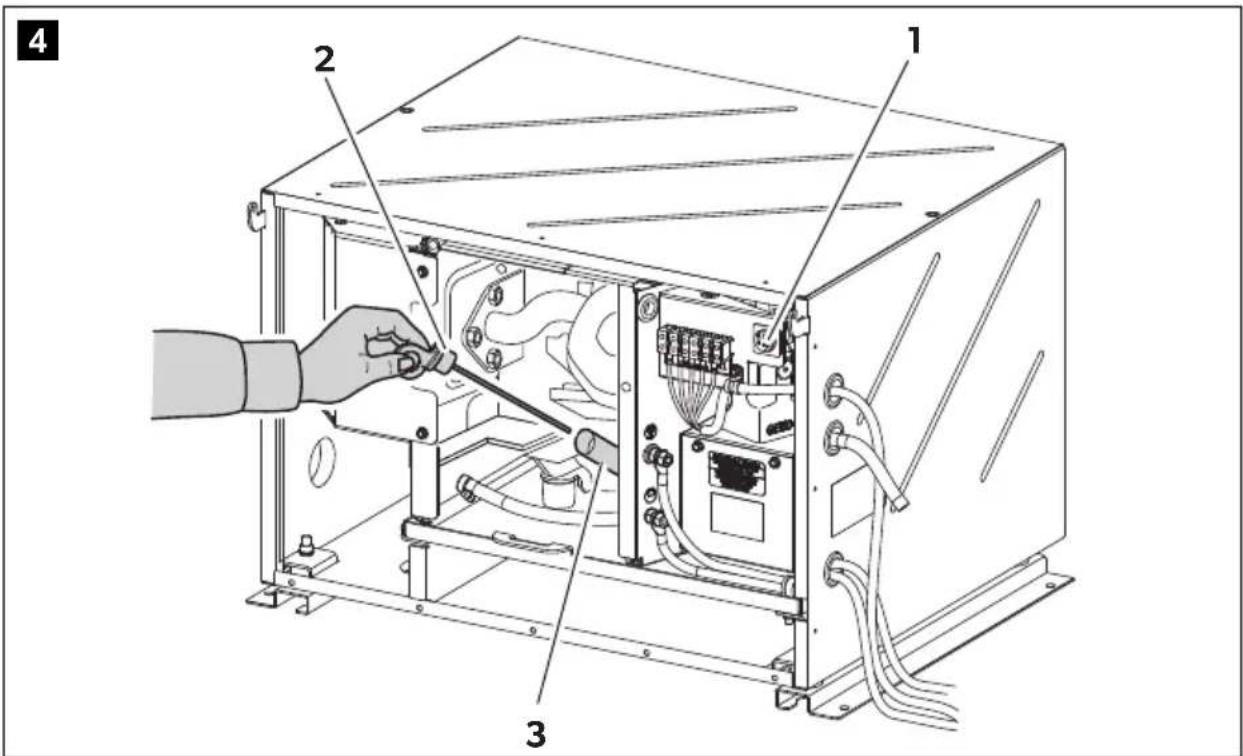
▶ Switch the generator to no function with the main switch (fig. 4 1, page 4).
▶Disconnect the positive terminal of the supply battery.
▶ Take the dipstick (fig. 4 2, page 4) out of the filler neck (fig. 4 3, page 4).
▶ Clean the dipstick (fig. 4 2, page 4) with a cloth.
▶ Put the dipstick (fig. 4 2, page 4) back into the filler neck (fig. 4 3, page 4).
▶ Take the dipstick (fig. 4 2, page 4) out of the filler neck.
▶ Check that the oil level is between the notch (maximum filling level) and the tip of the dipstick.
If not, top up with more oil.
▶ Put the dipstick (fig. 4 2, page 4) back into the filler neck (fig. 4 3, page 4).
▶Check that the oil level is not above the maximum level.
▶ Connect the generator to the positive terminal of the supply battery.
▶ Switch the generator to standby with the main switch (fig. 4 1, page 4).
▶Close the generator flap.
9 C I e a n i n g t

NOTICE! Damage hazard
- Do not clean the generator with a high-pressure cleaner. Exposure to water can damage the generator.
- Do not use sharp or hard objects or cleaning agents for cleaning as these may damage the generator.
- To clean the generator, use water with a gentle cleaning agent. Never use petrol, diesel or solvents.
▶Clean the generator with a damp cloth from time to time.
Remove any dirt from the air vents in the generator at regular intervals. Make sure you do not damage the grilles of the generator in the process.
10 Servicing the generator

NOTE
Find your Dometic service partner on the internet: service-location.dometic.com
10.1 Maintenance table

WARNING!
Only have maintenance work carried out by specialist personnel who are familiar with the relevant regulations. Inadequate maintenance may cause serious hazards.

NOTE
Have the following maintenance work performed at regular intervals or after the specified number of operating hours, whichever is sooner.
Interval Inspection/maintenance
| In the first month or after 20 hours. | ▶Change the oil. |
| ▶Check the air filter (chapter “Servicing the air filter” on page 22). |
| Every 3 months or after 50 hours. | ▶Check the air filter (chapter “Servicing the air filter” on page 22). |
| Every 6 months or after 100 hours. | ▶Change the oil. |
| ▶Check the spark plug (chapter “Servicing the spark plugs” on page 23). |
| Once a year or every 300 hours | ▶Check the valves. |
| ▶Check the fuel tank and fuel filter. |
| ▶Check the vibration damper. |
Every two years ▶Check the petrol supply lines.
10.2 Preparing maintenance work

CAUTION! Risk of injury
Note the following for all maintenance work:
- The generator must not be running.
- All the parts must be cooled down.
▶Open the generator flap.
▶ Switch the generator to no function with the main switch (fig. 2 1, page 3).
▶Disconnect the positive terminal of the supply battery.
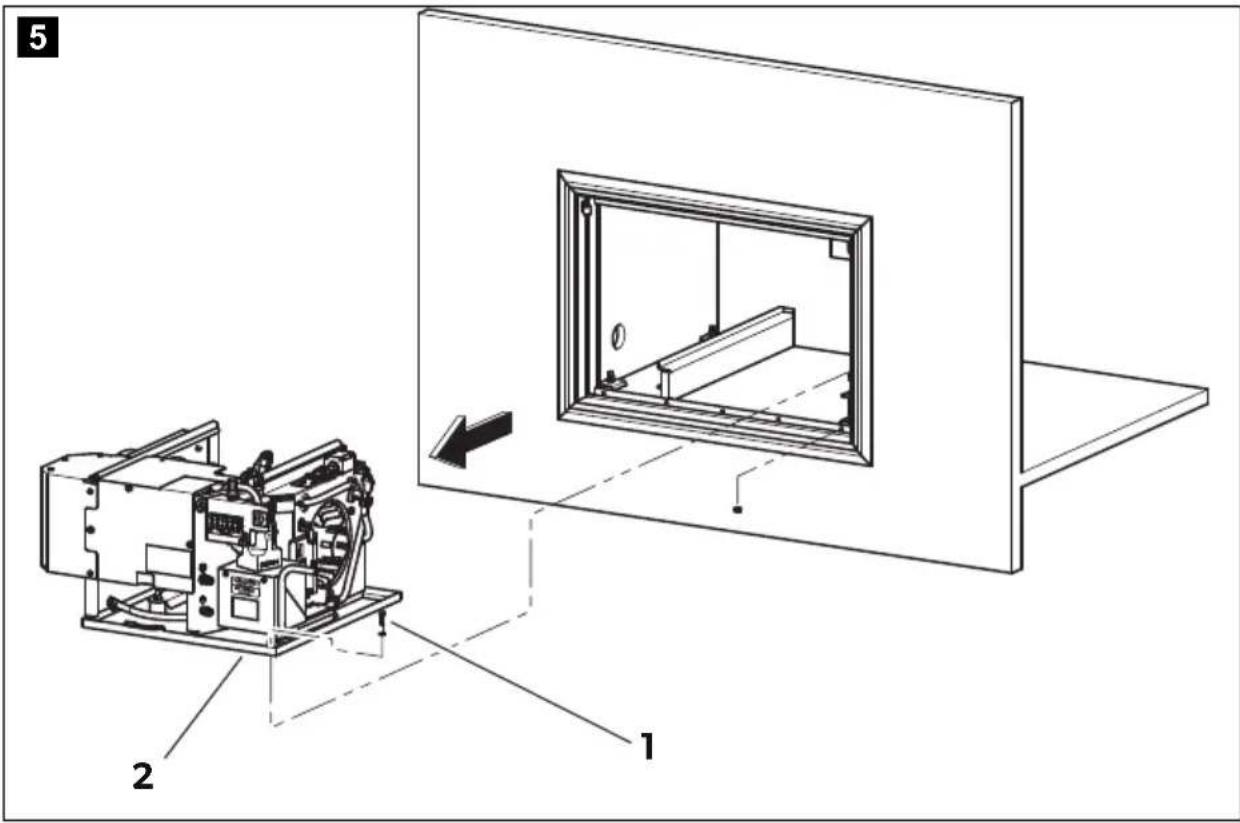
For maintenance work, you can take the generator out (fig. 5, page 5):

WARNING! Risk of injury
The mounting plate with generator is very heavy (> 70 kg) and could fall out the housing if you take it out too far.
▶Undo the fastening screws (1).
▶ Remove the mounting plate (2) with the generator from the housing (3).
10.3 Finishing maintenance work
▶ Connect the generator to the positive terminal of the supply battery.
▶ Switch the generator to standby with the main switch (fig. 4 1, page 4).
▶Close the generator flap.
10.4 Changing the oil

CAUTION! Risk of injury
Hot oil can cause burns.

NOTICE! Damage hazard
Only dispose of used oil at a specialist recycling station and observe the local laws for environmental protection.
You may use the following oil:
- SAE 5W-30 grade oil (can be used at any temperature).
- Oil with single grade oil viscosity.
Select the appropriate viscosity according to the average temperature on-site.
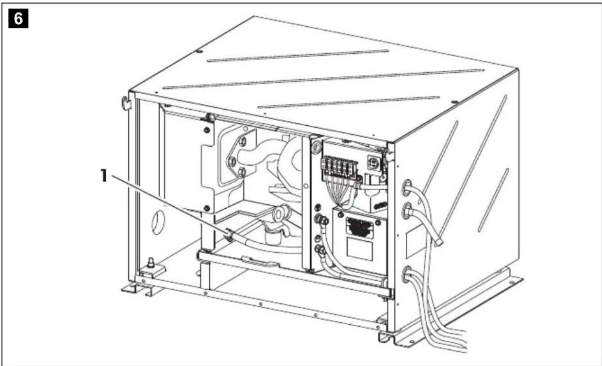
Change the oil as follows:
▶Allow the generator to run until warm so that the oil can drain off faster and completely.
▶ Place a suitable receptacle under the drain plug (fig. 6 1, page 5).
▶Remove the dipstick.
▶ Take out the drain plug (fig. 6 1, page 5).
√The oil drains off.
▶Pour fresh oil into the filler neck.
The amount of oil is: 1.1 l.
▶Put the drain plug in.
10.5 Servicing the air filter

WARNING! Danger of explosions
Do not use diesel oil or solvents with low boiling points for cleaning the air filter. They could ignite or explode.

NOTICE! Damage hazard
Never leave the engine running without an air filter. Otherwise this quickly wears out the engine.

NOTE
If the air filter is dirty, the air flow to the carburettor is reduced. Check the filter regularly so that the carburettor can function properly. Check this more frequently if the generator is being used in particularly dusty environments.
▶Prepare the maintenance work and pull the generator out of the housing slightly: see chapter "Preparing maintenance work" on page 20.
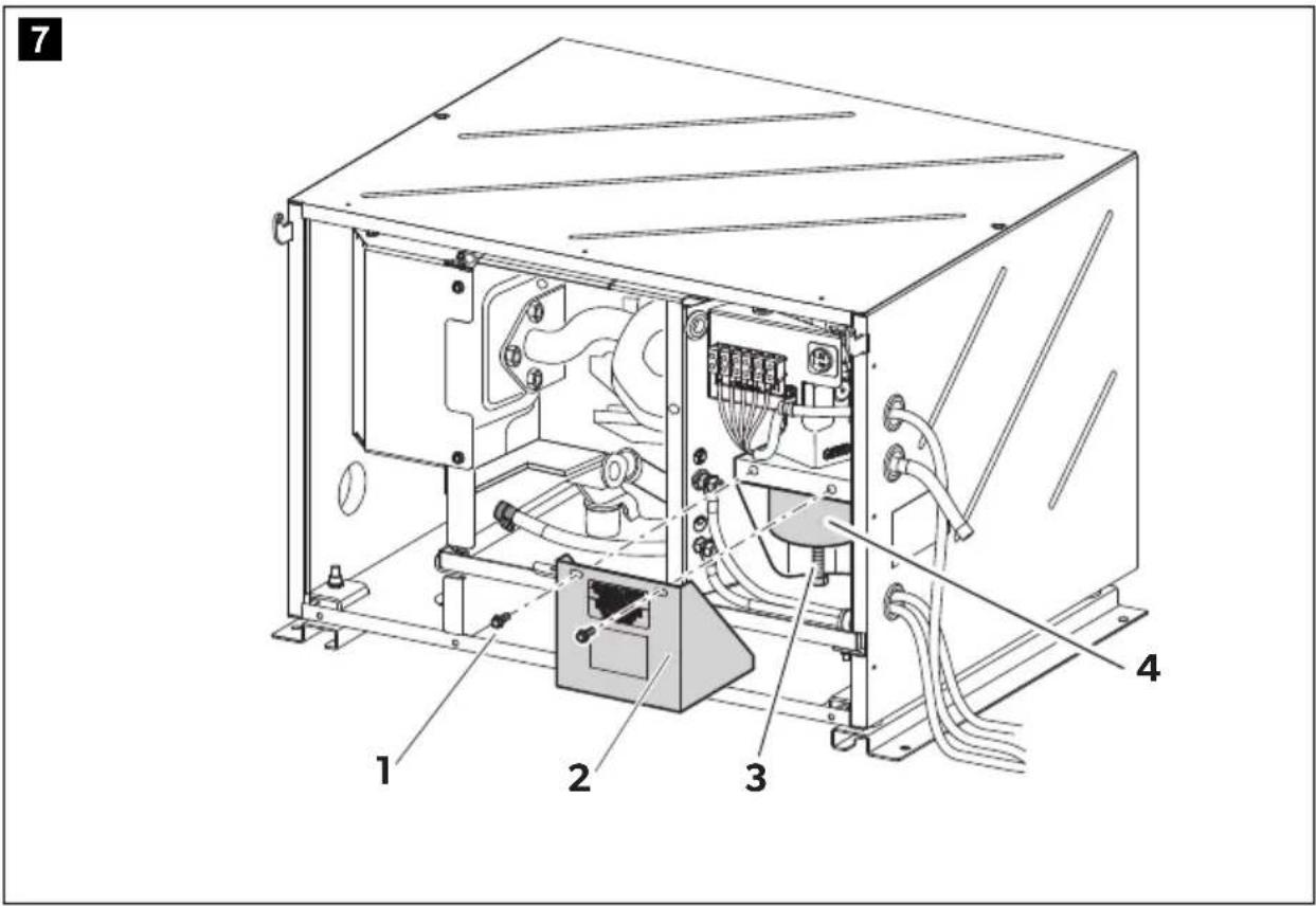
Remove the screws (fig. 7 1, page 6) and the filter cover (fig. 7 2, page 6).
▶ Remove the screw (fig. 7 3, page 6).
▶ Take out the air filter (fig. 7 4, page 6).
The air filter consists of two parts: a sponge filter and a paper filter.
▶ Check the condition of both parts of the filter carefully. Replace the damaged filter parts.
▶ Clean the undamaged filter parts; see the following section.
▶Put the filter in.
▶Reinstall the screw.
▶Put the filter cover on.
▶ Finish the maintenance work, see chapter "Finishing maintenance work" on page 21.
Cleaning the sponge filter
▶ Wash the sponge with a neutral detergent solution and rinse it thoroughly.
▶Leave the sponge to dry completely.
▶Soak the sponge in fresh engine oil.
▶ Squeeze out the excess oil.
Cleaning the paper filter
▶Knock the dirt off the paper by banging it lightly on a hard surface or use compressed air to blow through the filter.
Do not brush the paper as this will push the dirt into the fibres of the paper filter.
▶Change the paper filter if it is heavily soiled.
10.6 Servicing the spark plugs

NOTICE! Damage hazard
- Screw the spark plugs in carefully. A loose spark plug can get very hot and damage the engine.
- Only use the same type of spark plugs.
- When you insert a new spark plug, screw it in by 1/2 a turn once it is firmly on the washer. If you are using used spark plugs, turning them 1/8 or 1/4 is suffice.
Prepare the maintenance work, see chapter "Preparing maintenance work" on page 20.
▶Remove the spark plug connector.
▶Remove the spark plug using a spark plug wrench.
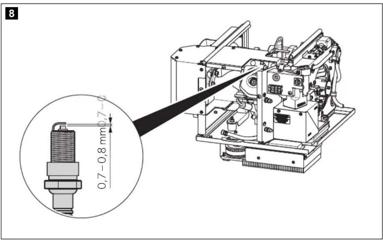
▶Make a visual inspection of the spark plug.
Replace the spark plug if it is clearly worn or the isolator is damaged or broken. If the spark plug is just dirty, clean it with a steel brush.
▶ Measure the distance between the electrodes with a thickness gauge (fig. 8, page 6). It must be 0.7–0.8 mm and can be corrected by bending the electrode if necessary.
▶Check whether the spark plug seal is intact.
▶Screw in the spark plug by hand to avoid damaging the thread.
▶ Tighten the spark plug using a spark plug wrench so that the washer is pressed together.
▶ Finish the maintenance work, see chapter "Finishing maintenance work" on page 21.
11 Troubleshooting
| Fault Cause Remedy |
| The control panel does not come on when the on/off switch is pressed. | Starter battery is flat. | ➢Charge the starter battery. |
| The fuse (if available) is blown. | ➢Contact an authorised workshop. |
| The starter does not work when the start button is pressed. | Starter battery is flat. | ➢Charge the starter battery. |
| The main switch is at “0”. | ➢Set the main switch to “1” or “1”. |
| Internal board is damaged. | ➢Contact an authorised workshop. |
| Starter is not receiving any power. | |
| The starter turns but the generator does not start. | No petrol. | ➢Fill up with petrol. |
| Too much oil in the engine. | ➢Drain the oil. |
| Spark plug is not receiving any power. | ➢Check the electric connections. |
| Carburettor is not receiving any petrol. | ➢Clean the carburettor. |
| Air intake is blocked. | ➢Check the air filter (see chapter “Servicing the air filter” on page 22). |
| Inverter is damaged. | ➢Contact an authorised workshop. |
| The generator tends to go off. | Too much oil in the engine. | ➢Drain the oil. |
| Load is over 6,2 kW. | ➢Switch off the consumers. |
| Carburettor is not receiving any petrol. | ➢Clean the carburettor. |
| Air intake is blocked. | ➢Check the air filter (see chapter “Servicing the air filter” on page 22). |
| Inverter is damaged. | ➢Contact an authorised workshop. |
| Electromagnet (inverter) is blocked. | |
| Air filter is dirty. | ➢Check the air filter (see chapter “Servicing the air filter” on page 22). |
| Fuel filter is dirty. | ➢Replace the fuel filter. |
| The generator is running but does not supply any voltage. | Inverter is damaged. | ➢Check the output wiring connection |
| RPM too low. | ➢Contact an authorised workshop. |
Fault Cause Remedy
| The generator starts up very fast and then the “GENERATOR ALERT” message appears. | The stepper motor is faulty. | ▶Contact an authorised workshop. |
| The generated voltage is unstable. | Inverter is damaged. | ▶Contact an authorised workshop. |
12 Warranty
The statutory warranty period applies. If the product is defective, please contact the service partner in your country (see back page).
Our experts will be happy to help you and will discuss the warranty process with you in more detail.
13 Disposal
▶ Place the packaging material in the appropriate recycling waste bins wherever possible.
If you wish to finally dispose of the product, ask your local recycling centre or specialist dealer for details about how to do this in accordance with the applicable disposal regulations.

Protect the environment!
Do not dispose of any batteries with general household waste.
Return defective or used batteries to your retailer or dispose of them at collection points.
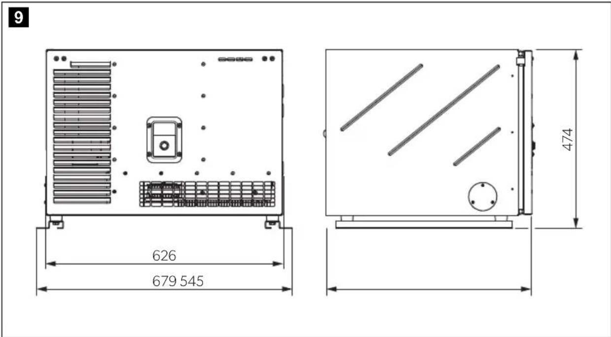
14 Technical data
| TEC60EV |
| Ref. no.: 9102900303 | |
| Rated output voltage: | 230 V~ / 50 Hz |
| Max. constant output (at 25 °C at sea level): | 6200 W |
| Battery charger output voltage: 12 V--- |
| Battery charger max. output current: | 30 A |
| Operating temperature range: -15 °C to +50 °C |
| Total harmonic distortion: <3 % | |
| Fuel: RON 91 regular grade petrol | |
| Consumption: max. 3.7 l/h | |
| Motor output: 6.6 kW (8.9 PS) | |
| Max. revolutions per minute: | 3600 min-1 |
| Motor oil: 1.1 l | |
| CO2 value 743 g/kW-hr | |
| Sound level: | 91 dB(A) |
| Sound level at distance of 7 m: | 66 dB(A) |
| Dimensions: | see fig. 9, page 5 |
| Weight: | 110 kg |
| Inspection/certification: |   |
This CO_2 measurement results from testing over a fixed test cycle under laboratory conditions a(n) (parent) engine representative of the engine type (engine family) and shall not imply or express any guarantee of the performance of a particular engine.
7 Description technique
service-location.dometic.com
WAARSCHUWING! Explosiegevaar!
service-location.dometic.com
service-location.dometic.com
PASS PÅ! Fare for skade
PASS PÅ! Fare for skade
PASS PÅ! Fare for skade
PASS PÅ! Fare for skade
PASS PÅ! Fare for skade
PASS PÅ! Fare for skade
PASS PÅ! Fare for skade
- Skru fast tennpluggene. Tennplugger som ikke er skrudd fast, kan bli svært varme og forårsake skader på motoren.
- Bruk kun likeverdige tennplugger.
- Når du setter inn en ny tennplugg, skrur du den fast en 1/2 omdreining til den sitter fast på mellomleggsskiven. Hvis man bruker brukte tennplugger, er det tilstrekkelig med en 1/8 eller 1/4 omdreining.
service-location.dometic.com
10.1 Huoltotaulukko

VAROITUS!
dometic.com/sales-offices