
TEC 30EV - Generator DOMETIC - Free user manual and instructions
Find the device manual for free TEC 30EV DOMETIC in PDF.

| Brand | DOMETIC |
| Model | TEC 30EV |
| Product type | Generator |
| Rated output voltage | 230 V~ / 50 Hz |
| Max. continuous power | 2500 W (at 25 °C, sea level) |
| Battery charger | Voltage 12 V---, max. current 10 A |
| Required starter battery | 12 V---, capacity ≥ 60 Ah, fuse 150 A |
| Fuel | Diesel (EN 590, DIN 51601-DK, BS 2869 A1/A2, ASTM D975 1D/2D) |
| Fuel consumption | 0.7 l/h |
| Oil sump capacity | 0.9 l |
| Guaranteed sound level | 84 dB(A) |
| Sound level at 7 m | 59 dB(A) |
| Dimensions | See fig. 20 page 16 of the manual |
| Weight | 70 kg |
| Operating temperature range | -15 °C to +50 °C |
| Insulation class | H |
| Certification | ZA du Pré de la Dame Jeanne, B. P. 5, F-60128 Plailly |
Frequently Asked Questions - TEC 30EV DOMETIC
User questions about TEC 30EV DOMETIC
0 question about this device. Answer the ones you know or ask your own.
Ask a new question about this device
Download the instructions for your Generator in PDF format for free! Find your manual TEC 30EV - DOMETIC and take your electronic device back in hand. On this page are published all the documents necessary for the use of your device. TEC 30EV by DOMETIC.
USER MANUAL TEC 30EV DOMETIC
natural_image
Exterior view of a Dometrić industrial control unit with black casing and connected cables (no visible text or symbols)TEC30D EV
EN
Generator
Installation Manual....17
DE
Generator
natural_image
Technical line drawings of two mechanical or electrical enclosure units labeled A and B, showing internal components and mounting brackets (no text or symbols beyond labels)
4
natural_image
Isometric diagram of a rectangular frame with dotted selection lines, no text or symbols present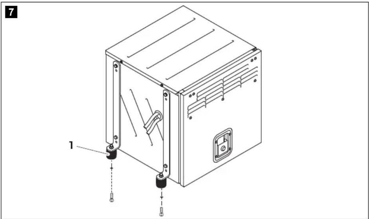
natural_image
Technical line drawing of a mechanical device with labeled parts (1 and 7), showing internal components and mounting features (no text or symbols beyond labels)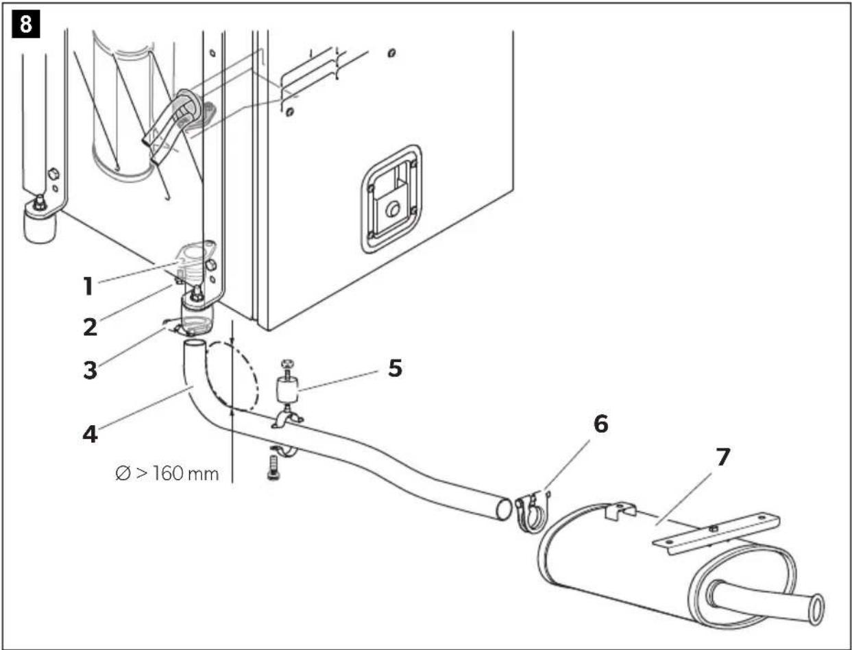
natural_image
Technical line drawing of a mechanical assembly with pipes, valves, and a central component (no text or symbols)
natural_image
Technical line drawing of a mechanical assembly with pipes, clamps, and mounting brackets (no text or symbols)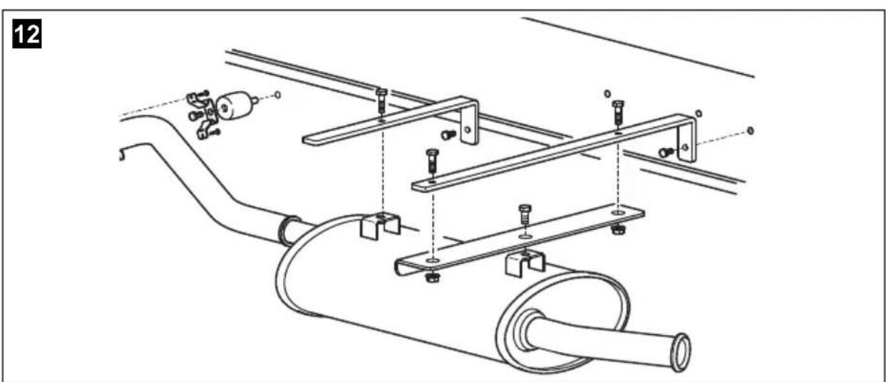
natural_image
Technical line drawing of a mechanical assembly with pipes, bolts, and a valve (no text or symbols)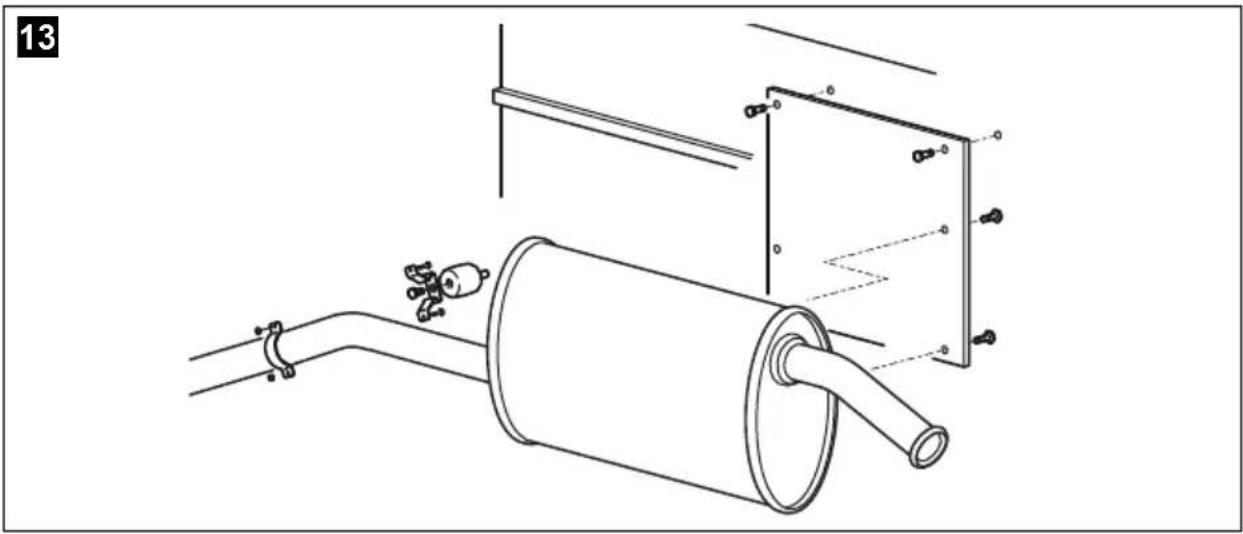
natural_image
Technical line drawing of a pipe assembly with a cylindrical component and attached panel (no text or symbols)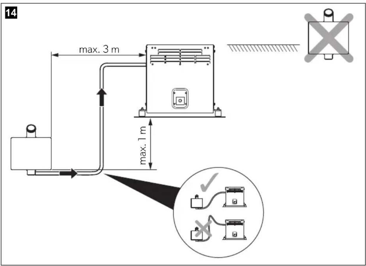
15
16
natural_image
Line drawing of a rectangular electronic device with a display and control panel (no text or symbols)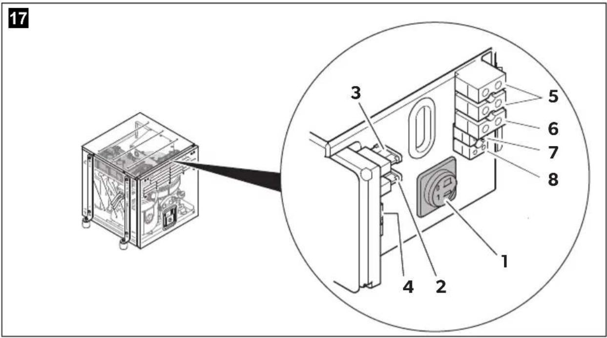
flowchart
graph TD
    A["1"] --> B["2"]
    B --> C["3"]
    C --> D["4"]
    D --> E["5"]
    E --> F["6"]
    F --> G["7"]
    G --> H["8"]
    H --> I["9"]
    I --> J["10"]
    J --> K["11"]
    K --> L["12"]
    L --> M["13"]
    M --> N["14"]
    N --> O["15"]
    O --> P["16"]
    P --> Q["17"]
    Q --> R["18"]
    R --> S["19"]
    S --> T["20"]
    T --> U["21"]
    U --> V["22"]
    V --> W["23"]
    W --> X["24"]
    X --> Y["25"]
    Y --> Z["26"]
    Z --> AA["27"]
    AA --> AB["SW"]
    style A fill:#f9f,stroke:#333
    style B fill:#f9f,stroke:#333
    style C fill:#f9f,stroke:#333
    style D fill:#f9f,stroke:#333
    style E fill:#f9f,stroke:#333
    style F fill:#f9f,stroke:#333
    style G fill:#f9f,stroke:#333
    style H fill:#f9f,stroke:#333
    style I fill:#f9f,stroke:#333
    style J fill:#f9f,stroke:#333
    style K fill:#f9f,stroke:#333
    style L fill:#f9f,stroke:#333
    style M fill:#f9f,stroke:#333
    style N fill:#f9f,stroke:#333
    style O fill:#f9f,stroke:#333
    style P fill:#f9f,stroke:#333
    style Q fill:#f9f,stroke:#333
    style R fill:#f9f,stroke:#333
    style S fill:#f9f,stroke:#333
    style T fill:#f9f,stroke:#333
    style U fill:#f9f,stroke:#333
    style V fill:#f9f,stroke:#333
    style W fill:#f9f,stroke:#333
    style X fill:#f9f,stroke:#333
    style Y fill:#f9f,stroke:#333
    style Z fill:#f9f,stroke:#333
    style AA fill:#f9f,stroke:#333
    style AB fill:#f9f,stroke:#333
    style AC fill:#f9f,stroke:#333
    style AD fill:#f9f,stroke:#333
    style AE fill:#f9f,stroke:#333
    style AF fill:#f9f,stroke:#333
    style AG fill:#f9f,stroke:#333
    style AH fill:#f9f,stroke:#333
    style AI fill:#f9f,stroke:#333
| bl br ge | gn gr or | |||||
| DE Blau | Braun Gelb Grün Grau Orange | |||||
| EN Blue | Brown Yellow | Green Grey Orange | ||||
| FR | Bleu | Marron | Jaune | Vert | Gris | Orange |
| ES | Azul | Marrón | Amarillo | Verde | Gris | Naranja |
| IT | Blu | Marrone | Giallo | Verde | Grigio | Arancione |
| NL Blauw | Bruin Geel | Groen Grijs Oranje | ||||
| DA | Blå | Brun | Gul | Grøn | Grå | Orange |
| SV | Blå | Brun | Gul | Grön | Grå | Orange |
| NO | Blå | Brun | Gul | Grønn | Grå | Oransje |
| FI | Sininen | Ruskea | Keltainen | Vihreä | Harmaa | Oranssi |
| RU | Синий | Коричневый | Желтый | Зеленый | Серый | Оранжевый |
| PL | Niebieski | Brązowy | Żółty | Zielony | Szary | Pomarańczowy |
| CS | Modrá | Hněda | Żlutá | Zelená | Šedá | Oranžová |
| SK | Modrá | Hnedá | Żltá | Zelená | Sivá | Oranžová |
| HU | Kék | Barna | Sárga | Zöld | Szürke | Narancs |
| pk rt sw vt ws | |||||
| DE Pink Rot Schwarz Violett Weiß | |||||
| EN Pink Red Black Violet White | |||||
| FR Rosa Rouge Noir Violeta Blanc | |||||
| ES Rose Rojo Negro | Lila | Blanco | |||
| IT | Rosa | Rosso | Nero | Violetto | Bianco |
| NL Roze Rood Zwart Paars | Wit | ||||
| DA | Lyserøde | Rød | Sort | Violet | Hvid |
| SV | Rosa | Röd | Svart | Violett | Vit |
| NO | Rosa | Rød | Svart | Fiolett | Hvit |
| FI | Pinkki | Punainen | Musta | Violetti | Valkoinen |
| RU | Розовый | Красный | Черный | Фиолетовый | Белый |
| PL | Różowy | Czerwony | Czarny | Fioletowy | Biały |
| CS | Růžová | Červená | Černá | Fialová | Bílá |
| SK | Ružová | Červená | Čierna | Fialová | Biela |
| HU | Rózsaszín | Piros | Fekete | Ibolya | Fehér |
20
natural_image
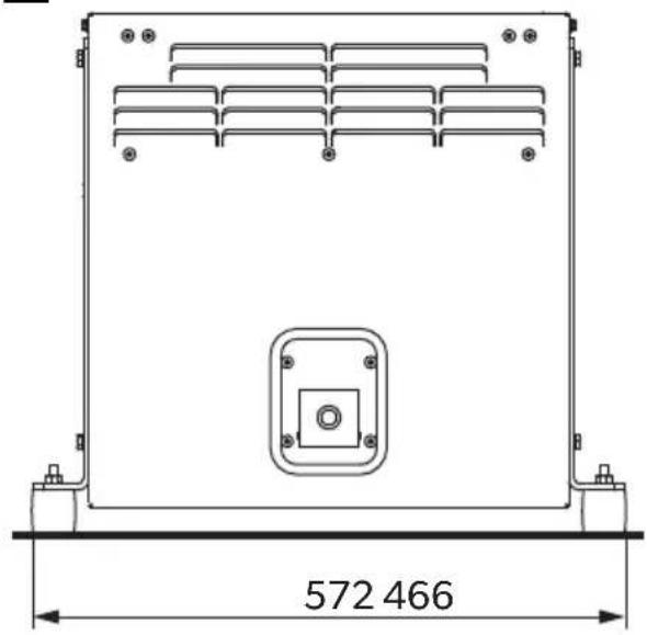
Technical line drawing of a rectangular electronic device with mounting feet and internal compartments, dimensioned as 572466 (no text or symbols beyond measurement label)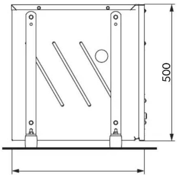
natural_image
Technical line drawing of a mechanical frame with dimension annotations (500 and 400 units), no readable text or symbols present.Please read this instruction manual carefully before installation and first use, and store it in a safe place. If you pass on the product to another person, hand over this instruction manual along with it.
Table of contents
1 Explanation of symbols....18
2 Safety and installation instructions .....18
3 Target group for this manual.... 20
4 Scope of delivery 20
5 Accessories....21
6 Intended use ....21
7 Labels....21
8 Technical description....21
9 Installation 22
10 Connecting the electrical power to the generator 25
11 Disposal....31
12 Technical data.... 32
1 Explanation of symbols

DANGER!
Safety instruction: Failure to observe this instruction will cause fatal or serious injury.

WARNING!
Safety instruction: Failure to observe this instruction can cause fatal or serious injury.

CAUTION!
Safety instruction: Failure to observe this instruction can lead to injury.

NOTICE!
Failure to observe this instruction can cause material damage and impair the function of the product.

NOTE
Supplementary information for operating the product.
2 Safety and installation instructions
Please observe the prescribed safety instructions and stipulations from the vehicle manufacturer and service workshops.
The manufacturer accepts no liability for damage in the following cases:
- Faulty assembly or connection
- Damage to the product resulting from mechanical influences and excess voltage
• Alterations to the product without express permission from the manufacturer - Use for purposes other than those described in the operating manual
Note the following basic safety information when using electrical devices to protect against:
- Electric shock
- Fire hazards
- Injury
2.1 Using the device

WARNING!
- Installing and repairing the device may only be carried out by qualified personnel who are familiar with the risks involved and the relevant regulations. Inadequate repairs may cause serious hazards. For repair service, please contact the service centre in your country (addresses on the back page).
• Electrical devices are not toys
Keep electrical devices out of reach of children or infirm persons. Do not allow them to use electrical devices without supervision.
- People (including children) whose physical, sensory or mental capacities prevent them from using this device safely may not be allowed to operate it without the supervision of a responsible adult.
- Exhaust fumes contain carbon monoxide which is a highly toxic, odourless and colourless gas. Do not inhale any exhaust fumes. Do not leave the generator motor running in a closed garage or in a room without windows.

CAUTION!
- Fire hazards
Do not install the generator in a box or room without any openings, but in well-ventilated spaces instead.
- Only operate the generator if you are certain that the housing and the cables are undamaged.
• Install the generator on a stable surface. - Do not tilt the generator more than 25^ from the vertical position.

NOTICE!
- Only use the device as intended.
- The generator is not suitable for use in water vessels.
- Do not make any alterations or conversions to the device.
2.2 Handling electrical cables

WARNING!
- The electrical power supply may only be connected by a qualified electrician (e.g. according to VDE 0100, Part 721 in Germany).

CAUTION!
- Attach and lay the cables so that they cannot be tripped over or damaged.

NOTICE!
- Use cable ducts to lay cables through walls with sharp edges.
- Do not lay loose or bent cables next to electrically conductive materials (metal).
- Do not pull on the cables.
3 Target group for this manual
The instructions in this manual are intended for qualified personnel at workshops who are familiar with the guidelines and safety precautions to be applied.
4 S c o p e o f d
No. in
fig. 1,
page 3
Number Description
11 Generator
21 Internal control panel
31 Silencer
41 Exhaust pipe, 2 m
51 Set mounting brackets for silencer
61 AG 102, changeover relay for making priority circuits
- 1 Extension cable for internal remote control
5 A c c e s s o r i
Available as accessory (not included in the scope of delivery):
Part designation Reference no.
| Damper 9102900028 |
| AG 101, tank 15 l, plastic 9102900009 |
| AG 100, tank 20 l, stainless steel 9102900011 |
| AG 150, pipe set for AG 100/AG 101 9102900003 |
| AG 125, flexible metal pipe for extending exhaust pipe, 5 m 9102900138 |
| AG 171, installation brackets (hanging installation) 9102900150 |
| AG 163, exhaust pipe fixing kit 9102900028 |
6 Intended use
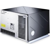
The TEC30D EV (ref. no. 9102900033) generator is designed for use in motor homes, camper vans and vehicles for commercial use.
The generator is not suitable for installation in water vessels.
The generator produces a pure sine wave voltage of 230 V/50 Hz which can be connected to the consumer with a total continuous load of 2500 W. The power quality is also suitable for sensitive consumers (such as PCs).
The generator can charge a 12 V battery.
7 L a b e l s
A label is attached to the generator. This label provides the user and fitter with information on the device specifications.
8 Technical description
Installing the generator must be configured according to the following options:
- Priority circuit which prioritises the 230 V external voltage over the voltage produced by the generator, see chapter "Creating a priority circuit" on page 30.
9 l n s t a l l a t

CAUTION! Beware of injury
The generator may only be installed by qualified personnel from a specialist company. The following information is intended for technicians who are familiar with the guidelines and safety precautions to be applied.
9.1 Note on installation
Read the installation manual carefully before you install the generator.
When installing the generator, note the following:

DANGER! Danger of electrocution
Disconnect all power supplies when working on the generator.

CAUTION! Beware of injury
- Improper installation of the generator can result in irreparable damage to the device and put the safety of the user at risk.
- Always wear the recommended protective clothing (e.g. protective goggles, gloves).
9.2 Securing the generator
Note on installation location
- Make sure that no combustible objects are stored or installed near the air outlet or the ventilation slots.
- If the installation location is closed on all sides create air intake openings in front of the maintenance cover with a cross-section of at least 240 cm ^2 .
- For safety reasons, note the location of existing wiring harnesses, wires and other components within the installation area, in particular those which are not visible, when installing the generator (when drilling or screwing etc.).
- Leave a space of at least 70 mm between the generator hood and surrounding parts so that sufficient space remains for cooling air to pass through.
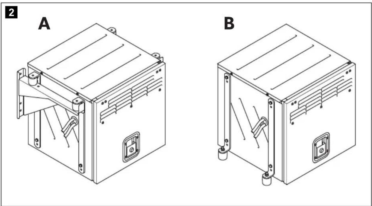
You can secure the generator in two ways:
• Hanging installation (fig. 2 A, page 3)
• Upright installation (fig. 2 B, page 3)
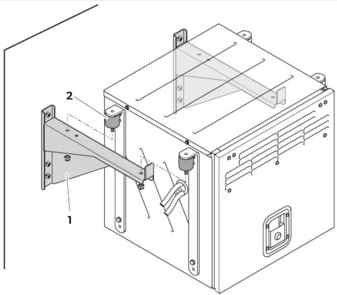
Hanging installation (A)
Proceed as follows:
▶ Remove the brackets (fig. 3 1, page 4).
▶ Mount the brackets upside down (fig. 3 2, page 4).
You can determine the exact position of the drillings using the drilling template which is included in the packaging (fig. 3 B, page 4).
▶ Fasten the mounting brackets (fig. 4 1, page 4; accessory, not included in the delivery) to the desired place.
▶ Fix the generator together with the dampers (fig. 4 2, page 4).
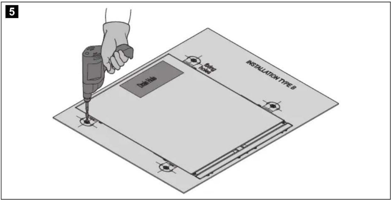
Upright installation (B)
Proceed as follows:
▶ Drill the mounting holes at the desired area using the drilling template which is included in the packaging (fig. 5, page 5).
▶ Drill the drain hole using the drilling template which is included in the packaging (fig. 5, page 5).
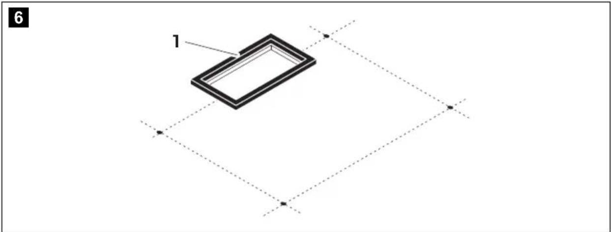
▶ Fit a seal (fig. 6 1, page 5) made of fire-retardant rubber with a thickness of at least 5 mm into the drain hole.
▶ Place the generator in the desired area.
▶ Fix the generator together with the dampers (fig. 7 1, page 5).
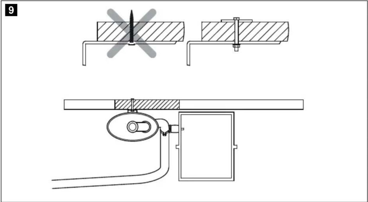
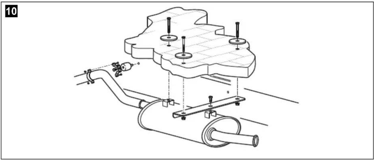
9.3 Securing the silencer
Observe the following instructions when installing the exhaust pipe:
- Do not create any sharp bends which will inhibit the flow of exhaust fumes.
- Comply with the minimum bending diameter of 160 mm to avoid cracks in the exhaust pipe.
- Use the exhaust pipe extension to extent the the exhaust pipe (see chapter "Accessories" on page 21).
Secure the extension to the vehicle floor.
▶ Secure the silencer (fig. 8 7, page 6) as in one of the alternatives shown in fig. 9, page 6 to fig. 13, page 8.
9.4 Installing the tank and fuel supply line
Please observe the following instructions for the installation location:
- The tank bottom must be positioned at a maximum of 1 m below the bottom of the generator.
- The top of the tank must not be higher than the top of the generator.
▶Lay the fuel hoses as straight as possible.
▶ Secure the tank (fig. 14, page 8).
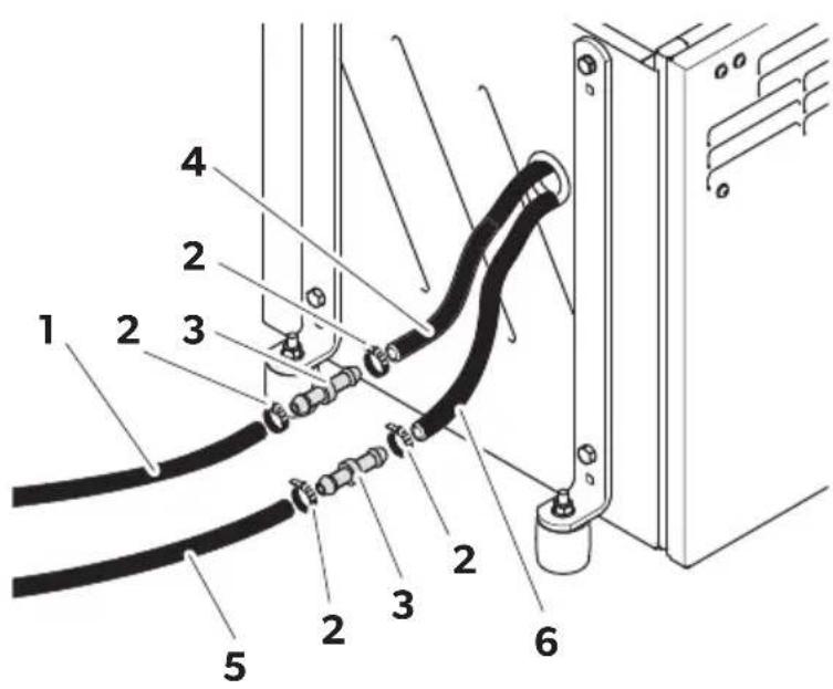
Connect the tank's supply hose (fig. 15 1, page 9) with a hose coupling (fig. 15 3, page 9) to the generator's supply hose (fig. 15 4, page 9). Secure the hoses with clamps (fig. 15 2, page 9).
Connect the tank's discharge hose (fig. 15 5, page 9) with a hose coupling (fig. 15 3, page 9) to the generator's discharge hose (fig. 15 6, page 9). Secure the hoses with clamps (fig. 15 2, page 9).
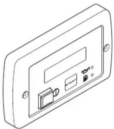
9.5 Mounting the remote control
Please observe the following instructions for the installation location:
- Observe the length of the extension cable from the remote control to the generator.
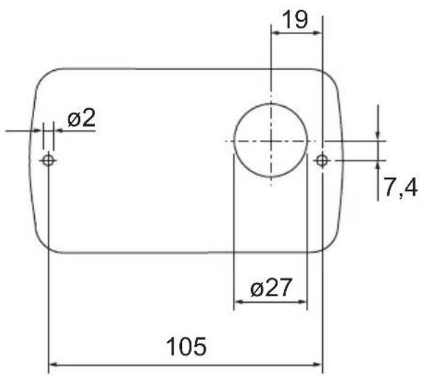
▶ Drill the holes as shown in fig. 16, page 9.
▶Insert the plug into the remote control.
▶Screw on the remote control.
10 Connecting the electrical power to the generator

DANGER! Danger of electrocution
Make sure there is no voltage at electrically operated components before carrying out work on them!

NOTICE!
Do not connect the battery before you made all other electrical connections.

NOTE
Observe the applicable guidelines in the country of the consumer.
10.1 Important notes on the electrical connection
- Only a qualified electrician should connect the generator to the electrical power.
- Check that the voltage specification on the type plate is the same as that of the power supply.
- Do not lay the 230 V\~ mains cable and the 12 V--- cable together in the same cable duct.
- Do not lay cables which are loose or bent next to electrically conductive material (metal).
- Connect the generator to a power circuit which can supply the necessary current (see chapter "Technical data" on page 32).
- Select the cross-section of the cable as follows:
-230 V: 2.5 mm ^4 - 12V battery charger: 2.5mm ^4
- Battery connection (length < 6 m): 16 mm ^2
- Battery connection (length > 6 m): 25 mm ^2
- Install a manual main switch which can disconnect all the consumers from the generator with the exception of the battery.
10.2 Control panel
No. in fig. 17, Description page 10
1 Main switch Switches the generator to standby or no function.
0: The generator is shut off from the supply battery.
1: The generator is powered by the supply battery and ready for start up.
2 Battery charger fuse Triggers if the AC voltage overloads.
3 Main fuse Triggers if the AC voltage overloads.
4 Control panel connection
5 230 V connection
6 Ground
712 V connection
8 Diesel oil gauge connection
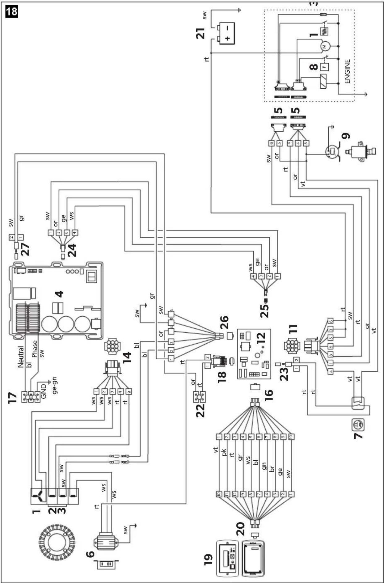
10.3 Circuit diagrams
The complete circuit diagram can be found in fig. 18, page 11.
| Item Description |
| 1 3-phase winding |
| 2 Auxiliary winding |
| 3 Auxiliary winding |
| 4 l n v e r t e r |
| 5 6 - p i n p l u g |
| 6 Battery charger |
| 7 Main switch |
| 8 P r e s s u r e s w |
| 9 F u e l p u m p |
| 10 Starter motor |
| 11 9-pin plug |
| 12 Control unit |
| 13 Thermal disconnector |
| 14 9-pin plug |
| 15 Electromagnet for cold start |
| 16 10-pin plug |
| 17 Connection terminals |
| 18 2-pin plug |
| 19 Remote control |
| 20 12-pin plug |
| 21 Battery |
| 22 Connection terminals |
| 23 2-pin plug |
| 24 4-pin plug |
| 25 4-pin plug |
Item Description
26 6-pin plug
27 2-pin plug
10.4 Connecting 230 V

NOTICE!
- Connect the changeover relay AG 102 to the vehicle's electrical system so that the generator is not damaged when the external mains is connected.
- Ensure that the electrical system is set up as follows:
- T N n e t w o r k :
The neutral conductor must be linked to the PE conductor on the terminal via a jumper with a minimum diameter of 2.5 mm^2 . To protect against automatic shutdown, make sure that a safety switch (FI switch, 30 mA) and an in all-pole overcurrent protection (e.g. circuit breaker, 13 A) are installed.
- | T n e t w o r k :
Ensure that an insulation monitor and an in all-pole overcurrent protection (e.g. circuit breaker, 13 A) are installed.
- Connect the generator so that it takes priority over the power supply (chapter "Creating a priority circuit" on page 30).
▶ Guide the 230 V connection cable through the cable passage in the housing and connect it to the 230 V terminals (fig. 17 5, page 10).
▶ Connect the earth cable to the earth connection on (fig. 17 6, page 10).
10.5 Connecting the remote control
▶Connect the remote control to the control panel of the generator using the extension cable provided on the plug for the remote control (fig. 17 4, page 10).
10.6 Connecting the float
▶ Connect the float from the tank to the Diesel oil gauge connection (fig. 17 8, page 10).
10.7 Connecting the battery charger
▶ Connect the positive terminal of the battery with the 12 V connection of the battery charger using a cable with a cross-section of 2.5 mm^2 (fig. 17 7, page 10).
If the battery to be charged is not also the starter battery, connect the negative terminal of the battery to be charged to the generator's earth cable (fig. 17 6, page 10).
10.8 Connecting the starter battery

NOTICE!
The starter battery must have 12 V and a capacity of at least 60 Ah.
▶Connect the positive terminal of the battery to the positive battery terminal connections (fig. 17 7, page 10) using a suitable cable:
- cable length < 6m : cross-section 16mm^2
- cable length >6 m: cross-section 25 ~mm^2
Fit a 150 A fuse in the positive cable near the positive terminal of the starter battery to protect the generator's electrical system.
▶Connect the negative terminal of the battery using a cable with a suitable cross-section (see above) to the ground connection (fig. 17 6, page 10).
▶ Connect the earth connection on the generator to the vehicle chassis. Remove any paint or rust from the chassis if necessary to ensure good contact.
▶Protect the connections by applying lubrication.
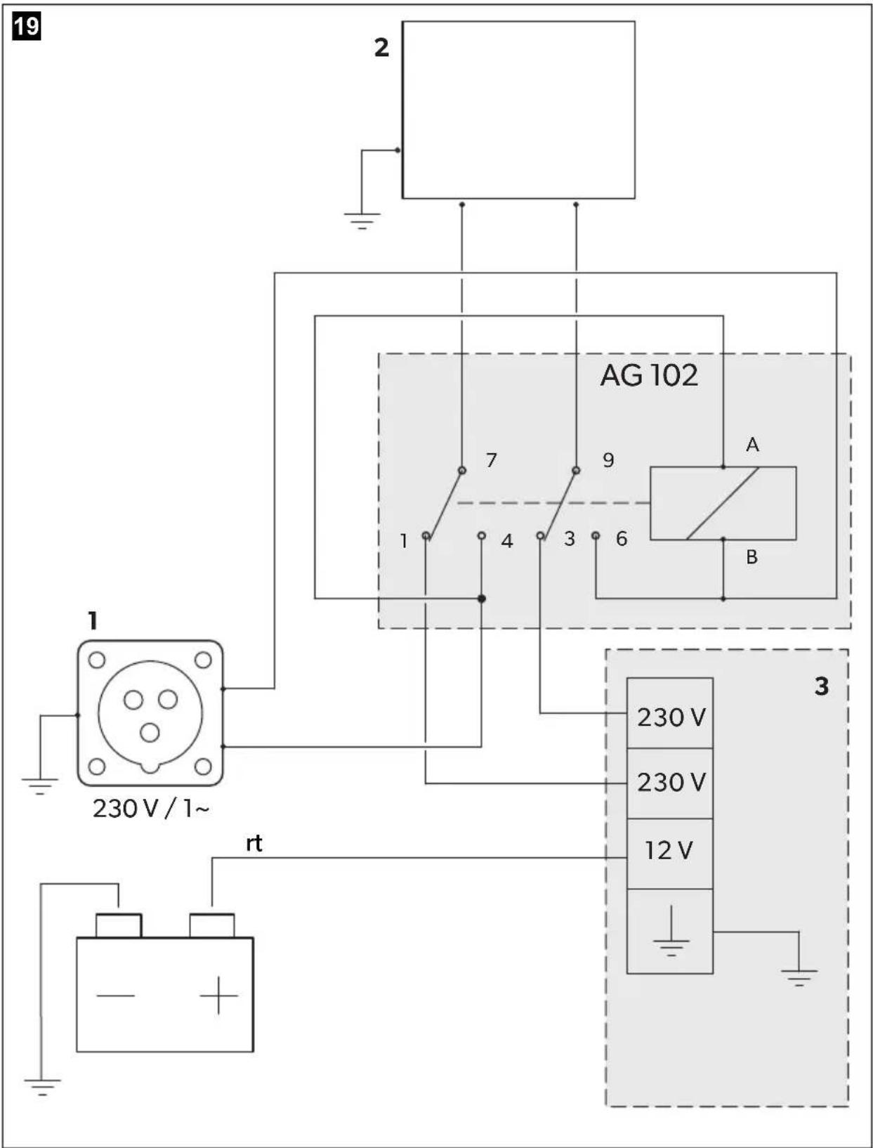
10.9 Creating a priority circuit
You can create a priority circuit using the AG 102 changeover relay whereby the external voltage supply has priority over the generator, see circuit diagram (fig. 19, page 15):
Item Description
1 230 V external voltage supply
2 Vehicle electrical distribution system
3 Control panel
▶Mount the AG 102 changeover relay in a suitable position.
▶ Disconnect the cable which links the mains input with the circuit breaker in the electrical distribution system of the vehicle so that the connections can be made as shown in the circuit diagram.
▶ Use a flat plug for connecting the cable to the switch.
▶ Connect A with plug-in sleeve 4 and B with plug-in sleeve 6.
▶ Connect the cable from the 230 V connection terminal of the generator to plug-in sleeve 1 and plug-in sleeve 3.
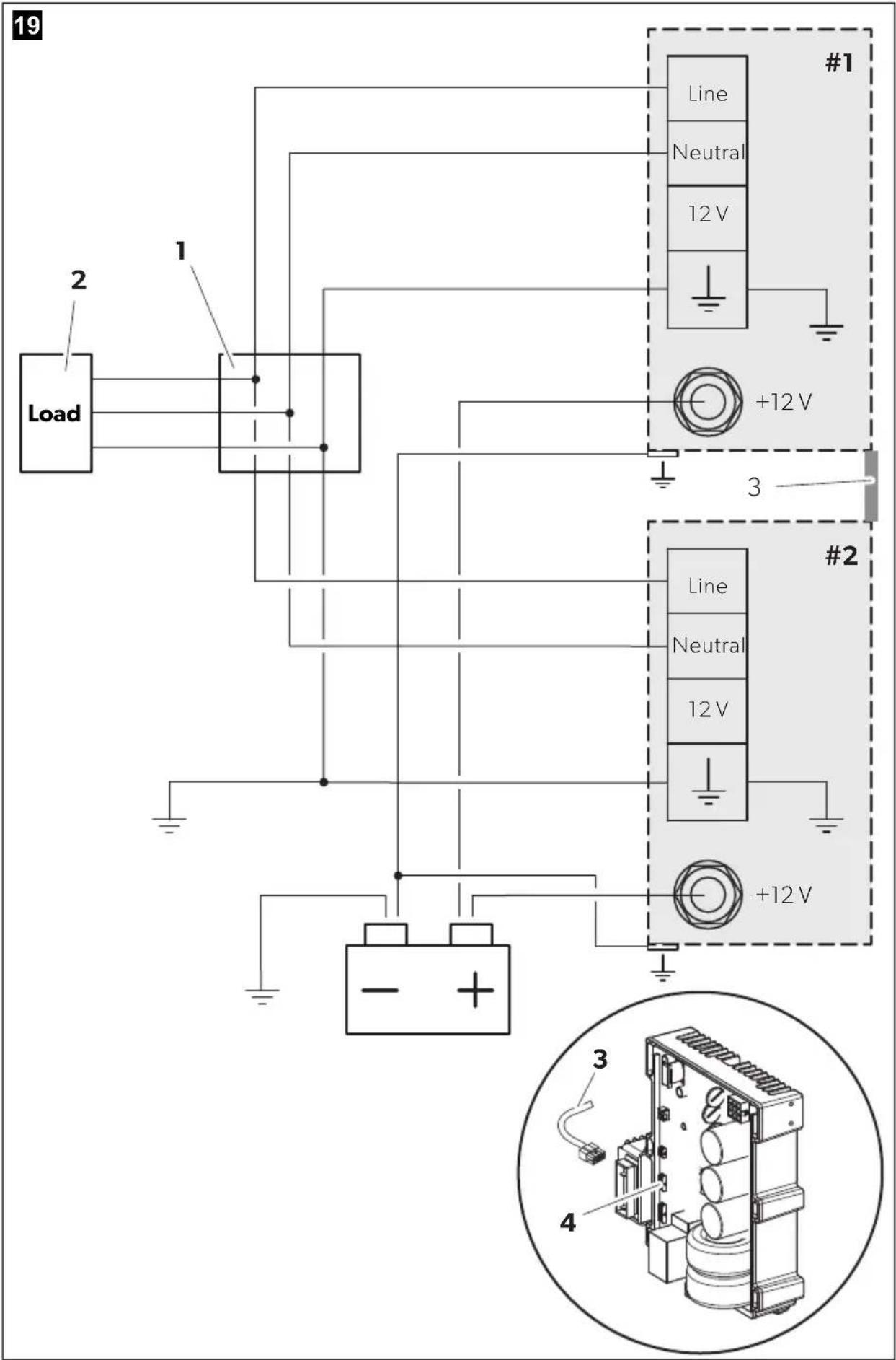
10.10 Connecting two genarators in parallel

NOTE
Use only one starter battery to start both generators.
When connecting the generators, note the following:
- It is not possible to connect more than two generators in parallel.
- To start one generator at a time the starter battery capacity has to be according to the generator manual (minimum capacity: 60 Ah).
To start both generators at the same time you have to double the battery capacity.
- The cross section of the battery connection cable for each generator has to be at least:
- 10 ~mm^2 if the total length is less than 6 ~m
- 16 ~mm^2 if the total length is more than 6 ~m

NOTE
- The maximum distance between each generator to the junction box is 15 m.
- The maximum length difference between the output cables of the generators must be 2 m.
Proceed as follows (fig. 19, page 12):
▶ Connect each generator to a junction box (1; not included in the scope of delivery).
The minimum cross section for each generator output cable is 2.5 mm^2 .
▶ Create a single output for the load (2) inside the junction box (1).
The minimum cross section for the parallel output cable is 6 mm^2 .
▶Connect the battery's negative pole to ground.
▶Connect the output ground cable to ground.
▶ Connect the change over switch AG 113 (available as accessory) between the junction box and the load.
To properly run the generators in parallel connect the inverters (4) of each generator using the parallel cable (3; available as accessory).
11 Disposal
▶ Place the packaging material in the appropriate recycling waste bins wherever possible.
If you wish to finally dispose of the product, ask your local recycling centre or specialist dealer for details about how to do this in accordance with the applicable disposal regulations.
12 Technical data
| Dometic TEC30D EV | |
| Ref. no.: 9102900033 | |
| Rated output voltage: | 230 V~/50 Hz |
| Max. constant output (at 25 °C at sea level): | 2500 W |
| Battery charger output voltage: 12 V--- | |
| Battery charger max. output current: 10 A | |
| Start battery Voltage: 12 V--- Capacity: ≥60 Ah | |
| Fuse for system protection: 150 A | |
| Operating temperature range: -15 °C to +50 °C | |
| Fuel: Diesel oil | (acc. EN 590, DIN 51601-DK, BS 2869 A1/A2, ASTM D975 1D/2D) |
| Consumption: 0.7 l/h | |
| Oil sump capacity: 0.9 l | |
| Motor output: | 3.4 kW (4.5 HP) |
| Engine speed: | 3300 min-1 |
| Guaranteed sound level: | 84 dB(A) |
| Sound level at distance of 7 m: | 59 dB(A) |
| Insulation class: | H |
| Dimensions: | see fig. 20, page 16 |
| Weight: | 70 kg |
| Inspection/certification: |  |
8 Description technique
Dometic Australia Pty. Ltd.
1 John Duncan Court
Varsity Lakes QLD 4227
1800212121
+61755076001
Mail: sales@dometic.com.au
AUSTRIA
Dometic Austria GmbH
Neudorferstraße 108
A-2353 Guntramsdorf
+43 2236 908070
+43 2236 90807060
Mail: info@dometic.at
BENELUX
Dometic Branch Office Belgium
Zincstraat 3
B-1500 Halle
+32 2 3598040
+32 2 3598050
Mail: info@dometic.be
BRAZIL
Dometic DO Brasil LTDA
Avenida Paulista 1754, conj. 111
SP 01310-920 Sao Paulo
+551132513352
+551132513362
Dometic Group Asia Pacific
Suites 2207-11 · 22/F · Tower 1
The Gateway · 25 Canton Road,
Tsim Sha Tsui · Kowloon
+852 2 4611386
+852 2 4665553
Mail: info@waeco.com.hk
HUNGARY
Dometic Zrt. Sales Office
Kerékgyártó u. 5.
H-1147 Budapest
+3614684400
+3614684401
Dometic Italy S.r.l.
Via Virgilio, 3
I-47122 Forlì (FC)
+39 0543 754901
+39 0543 754983
Mail: vendite@dometic.it
JAPAN
Dometic KK
Maekawa-Shibaura, Bldg. 2
2-13-9 Shibaura Minato-ku
Tokyo 108-0023
+81 3 5445 3333
+81 3 5445 3339
Mail: info@dometic.jp
MEXICO
Circuito Médicos No. 6 Local 1
Colonia Ciudad Satélite
CP 53100 Naucalpan de Juárez
Estado de México
+52 55 5374 4108
+52 55 5393 4683
Mail: info@dometic.com.mx
NETHERLANDS
Dometic Benelux B.V.
Ecustraat 3
NL-4879 NP Etten-Leur
+31 76 5029000
+31765029019
Mail: info@dometic.nl
NEW ZEALAND
Dometic New Zealand Ltd.
PO Box 12011
Penrose
Auckland 1642
+6496221490
+6496221573
Mail: customerservices@dometic.co.nz
NORWAY
Dometic Norway AS
∅sterøyveien 46
N-3232 Sandefjord
+47 33428450
+47 33428459
Mail: firmapost@dometic.no
POLAND
Dometic Poland Sp. z o.o.
Ul. Puławska 435A
PL-02-801 Warszawa
+48 22 414 3200
+48 22 414 3201
Mail: info@dometic.pl
PORTUGAL
Dometic Spain, S.L.
Komsomolskaya square 6-1
RU-107140 Moscow
+7 495 780 79 39
+7 495 916 56 53
Mail: info@dometic.ru
SINGAPORE
Dometic Pte Ltd
18 Boon Lay Way 06–140 Trade Hub 21
Singapore 609966
+65 6795 3177
+65 6862 6620
Mail: dometic@dometic.com.sg
SLOVAKIA
Dometic Slovakia s.r.o. Sales Office Bratislava
Nádražná 34/A
900 28 Ivánka pri Dunaji
黑/品 +421245529680
Mail: bratislava@dometic.com
SOUTH AFRICA
Dometic (Pty) Ltd.
Regional Office
South Africa & Sub-Saharan Africa
2 Avalon Road
West Lake View Ext 11
Modderfontein 1645
Johannesburg
+27114504978
+27114504976
Mail: info@dometic.co.za
SPAIN
Dometic Spain S.L.
Avda. Sierra del Guadarrama, 16
E-28691 Villanueva de la Cañada
Madrid
+34 91 833 60 89
+34 900 100 245
Mail: info@domelic.es
SWEDEN
Dometic Scandinavia AB
Gustaf Melins gata
Dometic Switzerland AG
Riedackerstrasse 7a
CH-8153 Rümlang
+41 44 8187171
+41 44 8187191
Mail: info@dometic.ch
UNITED ARAB EMIRATES
Dometic Middle East FZCO
P.O.Box17860
S-D 6, Jebel Ali Freezone
Dubai
+97148833858
+97148833868
Mail: info@dometic.ae
UNITED KINGDOM
Dometic UK Ltd.
Dometic House, The Brewery
Blandford St. Mary
Dorset DT11 9LS
+44 344 626 0133
+44 344 626 0143
Mail: customerservices@dometic.co.uk
USA
Dometic RV Division
1120 North Main Street
Elkhart, IN 46515
+1574-264-2131


- TEC30D EV
- Generator
- Table of contents
- Explanation of symbols
- DANGER!
- WARNING!
- CAUTION!
- NOTICE!
- NOTE
- Safety and installation instructions
- Please observe the prescribed safety instructions and stipulations from the vehicle manufacturer and service workshops.
- Using the device
- • Electrical devices are not toys
- - Fire hazards
- Handling electrical cables
- Target group for this manual
- S c o p e o f d
- A c c e s s o r i
- Intended use
- L a b e l s
- Technical description
- l n s t a l l a t
- CAUTION! Beware of injury
- Note on installation
- DANGER! Danger of electrocution
- Securing the generator
- Note on installation location
- Hanging installation (A)
- Upright installation (B)
- Securing the silencer
- Installing the tank and fuel supply line
- Mounting the remote control
- Connecting the electrical power to the generator
- Important notes on the electrical connection
- Control panel
- Circuit diagrams
- Item Description
- Connecting 230 V
- Connecting the remote control
- Connecting the float
- Connecting the battery charger
- Connecting the starter battery
- Creating a priority circuit
- Connecting two genarators in parallel
- Disposal
- Description technique
- Dometic Australia Pty. Ltd.
- AUSTRIA
- Dometic Austria GmbH
- BENELUX
- Dometic Branch Office Belgium
- BRAZIL
- Dometic DO Brasil LTDA
- Dometic Group Asia Pacific
- HUNGARY
- Dometic Zrt. Sales Office
- Dometic Italy S.r.l.
- JAPAN
- Dometic KK
- MEXICO
- NETHERLANDS
- Dometic Benelux B.V.
- NEW ZEALAND
- Dometic New Zealand Ltd.
- NORWAY
- Dometic Norway AS
- POLAND
- Dometic Poland Sp. z o.o.
- PORTUGAL
- Dometic Spain, S.L.
- SINGAPORE
- Dometic Pte Ltd
- SLOVAKIA
- Dometic Slovakia s.r.o. Sales Office Bratislava
- SOUTH AFRICA
- Dometic (Pty) Ltd.
- Regional Office
- South Africa & Sub-Saharan Africa
- SPAIN
- Dometic Spain S.L.
- SWEDEN
- Dometic Scandinavia AB
- Dometic Switzerland AG
- UNITED ARAB EMIRATES
- Dometic Middle East FZCO
- UNITED KINGDOM
- Dometic UK Ltd.
- USA
- Dometic RV Division
Brand : DOMETIC
Model : TEC 30EV
Category : Generator