PerfectPower DCC 121240 - Battery charger DOMETIC - Free user manual and instructions
Find the device manual for free PerfectPower DCC 121240 DOMETIC in PDF.

User questions about PerfectPower DCC 121240 DOMETIC
0 question about this device. Answer the ones you know or ask your own.
Ask a new question about this device
Download the instructions for your Battery charger in PDF format for free! Find your manual PerfectPower DCC 121240 - DOMETIC and take your electronic device back in hand. On this page are published all the documents necessary for the use of your device. PerfectPower DCC 121240 by DOMETIC.
USER MANUAL PerfectPower DCC 121240 DOMETIC
Please read this instruction manual carefully before installation and first use, and store it in a safe place. If you pass on the product to another person, hand over this instruction manual along with it.
Table of contents
1 Description of symbols 8
2 General safety instructions 8
3 Scope of delivery 12
4 Accessories 13
5 Target group for this manual. 13
6 Intended use 13
7 Technical description 14
8 Mount charging converter 17
9 Connect charging converter 18
10 Use charging converter 20
11 Maintaining and cleaning the charging converter. 22
12 Troubleshooting 23
13 Warranty 23
14 Disposal. 23
15 Technical data 24
1 Description of symbols

DANGER!
Safety instruction: Failure to observe this instruction will cause fatal or serious injury.

WARNING!
Safety instruction: Failure to observe this instruction can cause fatal or serious injury.

CAUTION!
Safety instruction: Failure to observe this instruction can lead to injury.

NOTICE!
Failure to observe this instruction can cause material damage and impair the function of the product.

NOTE
Supplementary information for operating the product.
2 General safety instructions
The manufacturer accepts no liability for damage in the following cases:
- Faulty assembly or connection
- Damage to the product resulting from mechanical influences and excess voltage
- Alterations to the product without express permission from the manufacturer
- Use for purposes other than those described in the operating manual
For protection, pay close attention to the following basic safety information when using electrical devices:
Electric shock
• F i r e h a z a r d s
- l n j u r y
2.1 General safety

DANGER!
- In the event of fire, use a fire extinguisher which is suitable for electrical devices.

WARNING!
- Only use the product as intended.
- Ensure that the red and black terminals never come into contact with each other.
- Disconnect the product from the battery
- each time before cleaning and maintenance
- before a fuse change (only by specialists)
- if you disassemble the product:
- Detach all connections.
- Make sure that no voltage is present on any of the inputs and outputs.
- The product may not be used if the product itself or the connection cable are visibly damaged.
- If the power cable for this product is damaged, it must be replaced by the manufacturer, customer service or a similarly qualified person in order to prevent safety hazards.
- This product may only be repaired by qualified personnel. Inadequate repairs may cause serious hazards.
- This product can be used by children aged 8 years or over, as well as by persons with diminished physical, sensory or mental capacities or a lack of experience and knowledge, providing they are supervised or have been taught how to use the product safely and are aware of the resulting risks.
- Electrical devices are not toys. Always keep and use the product out of the reach of children.
- Children must be supervised to ensure that they do not play with the product.

NOTICE!
- Before start-up, check that the voltage specification on the type plate is the same as that of the power supply.
- Ensure that other objects cannot cause a short circuit to the contacts of the product.
- Store the product in a dry and cool place.
2.2 Safety when installing the product

DANGER!
- Never mount the product in areas where there is a risk of gas or dust explosion.

CAUTION!
- Ensure a secure stand!
The product must be set up and fastened in such a way that it cannot tip over or fall down.

NOTICE!
- Do not expose the product to any heat source (such as direct sunlight or heating). Avoid additional heating of the product.
- Set up the product in a dry location where it is protected against splashing water.
2.3 Safety when connecting the product electronically

DANGER! Danger of fatal electric shock!
- For installation on boats:
If electrical devices are incorrectly installed on boats, this can lead to corrosion damage on the boat. Have the product installed by a qualified (boat) electrician.
- If you are working on electrical systems, ensure that there is somebody close at hand who can help you in emergencies.

WARNING!
- Make sure that the lead has a sufficient cross-section.
- Lay the cables so that they cannot be damaged by the doors or the bonnet.
Crushed cables can lead to serious injury.

CAUTION!
- Lay the cables so that they cannot be tripped over or damaged.

NOTICE!
- Use ductwork or cable ducts if it is necessary to lay cables through metal panels or other panels with sharp edges.
-
Do not lay the AC cable and DC cable in the same conduit (empty pipe).
-
Do not lay the cables so that they are loose or heavily kinked.
- Firmly secure the cables.
- Do not pull on the cables.
2.4 Safety when operating the product

WARNING!
- If the product is used in facilities with open lead acid batteries, the room must be well ventilated. These batteries give off explosive hydrogen gas that can be ignited by sparks on electrical connections.

CAUTION!
D o not operate the product
- In salty, wet or damp environments
- In the vicinity of corrosive fumes
- In the vicinity of combustible materials
-In areas where there is a danger of explosions
- Before activating, ensure that the power supply line and plug are dry.
- Always disconnect the power supply when working on the product.
- Please be aware that parts of the product may still produce voltage even after activation of the safety guard (fuse).
- Do not disconnect any cables when the product is still in use.

NOTICE!
- Make sure the air inlets and outlets of the product are not covered.
- Ensure good ventilation.
2.5 Safety precautions when handling batteries

WARNING!
- Batteries may contain aggressive and corrosive acids. Avoid battery fluid coming into contact with your body. If your skin does come into contact with battery fluid, thoroughly wash the part of your body in question with water.
If you sustain any injuries from acids, contact a doctor immediately.

CAUTION!
- When working on batteries, do not wear any metal objects such as watches or rings.
Lead acid batteries can cause short circuits which can cause serious injuries.
- Danger of explosions!
Never attempt to charge a frozen or defective battery. In this case place the battery in a frost-free area and wait until the battery has adjusted to the ambient temperature. Then start the charging process.
- Wear goggles and protective clothing when you work on batteries. Do not touch your eyes when you working on batteries.
- Do not smoke and ensure that no sparks can arise in the vicinity of the engine or battery.

NOTICE!
- Only use rechargeable batteries.
- Use sufficient cable cross sections.
- Protect the positive conduit with a fuse.
- Prevent any metal parts from falling on the battery. This can cause sparks or short circuit the battery and other electrical parts.
- Make sure the polarity is correct when connecting.
- Follow the instructions of the battery manufacturer and those of the manufacturer of the system or vehicle in which the battery is used.
- If you need to remove the battery, disconnect it first from the ground connection. Disconnect all connections and all consumers from the battery before removing it.
3 S C O P E O F D
Description
1 Battery charger
- Installation and operating manual
4 A C C e s o r
Available as accessories (not included in the scope of delivery):
Description Ref. no.
Temperature sensor TS-1 9600000099
5 Target group for this manual
The chapter "Connect charging converter" on page 18 chapter is solely intended for qualified professionals who are familiar with the relevant VDE regulations.
All other chapters are intended for the users.
6 Intended use
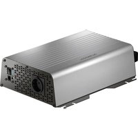
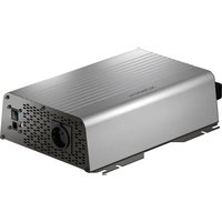
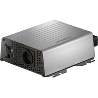
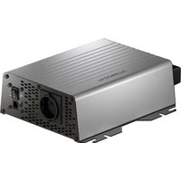
The PerfectCharge DCC battery chargers can charge batteries used on board vehicles or boats while driving, or supply them with a maintenance voltage for power generation. Additionally, the devices can be used as a stable power supply.
The DCC battery chargers are used for continuous charging of supply or on-board batteries (body batteries):
- 12 V= Charge converter: DCC1212-10, DCC1212-20, DCC1212-40
- 12V = Voltage converter: DCC2412-20, DCC2412-40
- 24 V=Charging converter: DCC2424-40
- 24 V=Voltage converter: DCC1224-10, DCC1224-20
The DCC battery chargers are used to charge the following battery types:
- Lead acid batteries
- Lead gel batteries
Fleece batteries (AGM batteries) - Dometic eStore lithium batteries

NOTICE!
Check the charging requirements from the battery manufacturer before charging your battery.
Do not use the device under any circumstances to charge other types of batteries (ex. NiCd, NiMH, etc.).

WARNING! Danger of explosions!
- Do not charge batteries with a cell conclusion. The oxyhydrogen they produce can cause explosions.
- Do not charge lead acid batteries in unventilated rooms. The oxyhydrogen they produce can cause explosions.
- Do not charge NiCd batteries or non-rechargeable batteries with this device. The sleeves of these batteries can explode.
7 Technical description
Because of its low weight and compact design, the charging converter can easily be installed in RVs, commercial vehicles or motor and sailing yachts. While driving it charges batteries that are used on board vehicles or boats to generate power or supplies them with a retention voltage so that they do not unload.
The 12V = = or 24V = = voltage from a vehicle or boat battery is transformed into a stable 12V = = or 24V = = DC voltage.
The isolation of the input and output voltages means the output voltage can be kept stable without interference from the input circuit.
The charging converter is switched on via a 12/24 V signal:
D + s i g n a l
- alternator signal (terminal 15)
- a switched input signal

NOTICE!
When terminal 15 is used, the starter battery may discharge even when the engine is off, if the ignition is set to "ON".
The battery charger has various protective mechanisms:
- High voltage shutdown: The battery charger shuts itself off when the voltage exceeds the cut-off value. It restarts when the voltage returns to the restart value.
- Low voltage shutdown: The battery charger shuts itself off when the voltage sinks below the cut-off value. It restarts when the voltage rises to the restart value.
- High temperature shutdown: The battery charger switches off when the temperature inside the device exceeds a cut-off value. It restarts when the voltage rises to the restart value.
- Protection against short circuit: The LED on the battery charger signals a malfunction if a short circuit has been generated. The device fuse must be replaced by a professional after it has been triggered by excess current.

NOTE
The individual values are found in chapter "Protective devices" on page 27.
The battery charger can be adapted to different battery types via DIP switches.
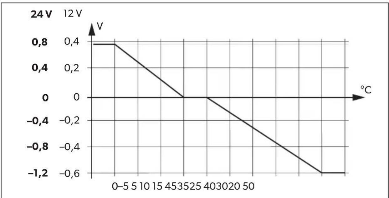
When a TS-1 temperature sensor is connected, the charging converter adjusts the charging voltage according to the measured temperature, see chapter "Technical data" on page 24.
7.1 Connections and controls
| Item in fig. 1, Description page 3 |
| 1 Input terminals (+) of starter battery |
| 2 Input terminals (-) of starter battery |
| 3 Control cable (I1) for turning on the vehicle with on-board voltage (D+ or terminal 15 (ignition)) |
| 4 LED display |
| 5 Power regulation (I2) to limit the charging current to 5 A |
| 6 RJ11 terminal: Connection of a temperature sensor (accessory) |
| 7 Dip switch, see chapter “Adjust charging converter” on page 20 |
| 8 Output terminals (+) to the body battery |
| 9 Output terminals (-) to the body battery |
7.2 Battery charging function
The charging characteristics are referred to as IUOU characteristics.
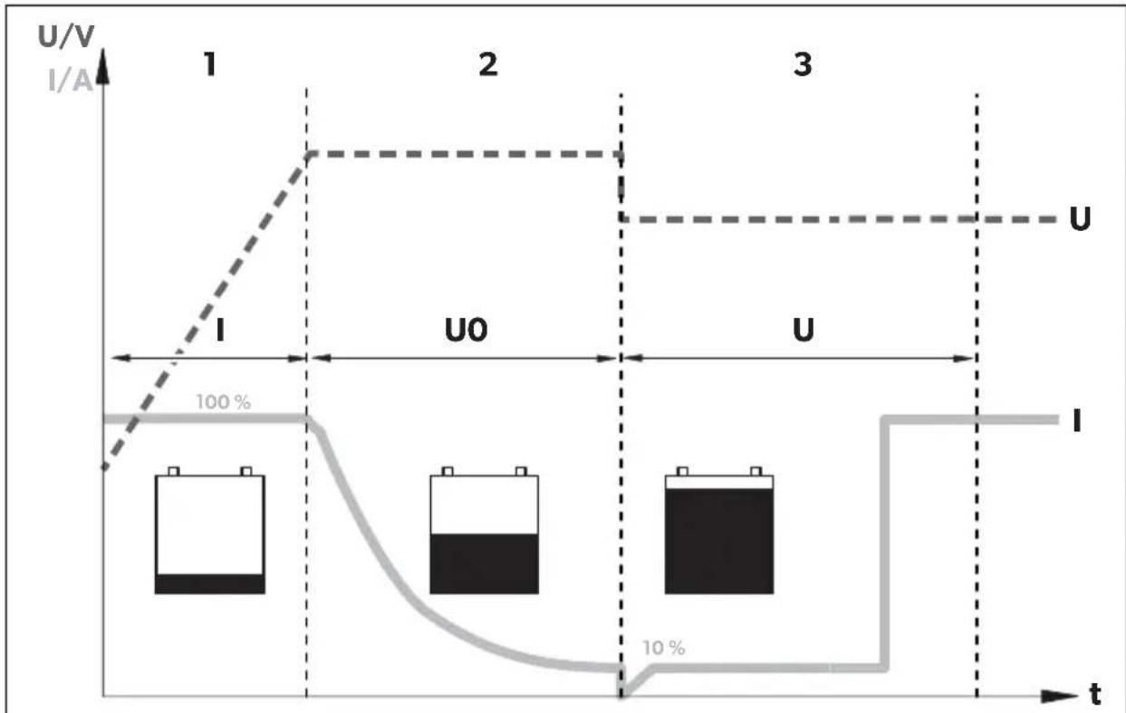
1: I phase (bulk)
At the beginning of the charging process, the flat battery is charged with a constant current (100% charge current) until the battery voltage reaches the charging end voltage. The charging current decreases when the battery has reached this charging level.
2: U0 phase (absorption)
Now the absorption charging process (U0 phase) begins, where the duration depends on the battery. The voltage remains constant (U0).
This phase is limited to maximal 3 hours to prevent overcharging the battery while driving.
3: U phase (float)
After the U0 phase, the battery charger switches to conservation charging function (U phase).
8 Mo u n t c h a
8.1 Tools required
For the electrical connection you will need the following tools:
- Cr i m p i n g t o o l
- 4 flexible connection cables: + and - for the starter battery, + and - for the body battery. 1 flexible signal cable for connection to D+ or the ignition. The required cross-section can be found in the table chapter "Connect charging converter" on page 19.
- Cable lugs and conductor sleeves
For fastening the battery charger you will need the following tools:
- Machine bolts (M4) with washers and self-locking nuts or
- self-tapping screws or wood screws.
8.2 Installation instructions
When selecting the installation location, pay attention to the following instructions:
- The battery charger can be installed horizontally as well as vertically.
- The battery charger must be installed in a place that is protected from moisture.
- The battery charger may not be installed in the presence of flammable materials.
- The battery charger may not be installed in a dusty environment.
- The place of installation must be well ventilated. A ventilation system must be available for installations in small, enclosed spaces. The minimum clearance around the battery charger must be at least 5 cm (fig. 2, page 4).
- The battery charger air inlet and air outlet must remain free.
- At ambient temperatures higher than 40^ (ex. in engine or boiler rooms, direct sunlight), the battery charger may switch off, although the power of the connected loads is below the rated load (derating).
- The device must be installed on a level and sufficiently sturdy surface.
8.3 Charging converter

NOTICE!
Before drilling any holes, make sure that no electrical cables or other parts of the vehicle can be damaged by drilling, sawing and filing.
Pay attention to the distance specifications (fig. 2, page 4).
Mount the charging converter as shown (fig. 3, page 4).
9 Connect charging converter

WARNING!
Do not reverse the polarity. Reverse polarity of the battery connections can cause injury and damage the device.

CAUTION!
- Avoid coming into contact with the battery fluid under any circumstances.
- Batteries with a cell short circuit may not be charged as explosive gases may form due to overheating of the battery.

NOTICE!
Tighten the nuts and bolts with a maximum torque of 12 - 13Nm . Loose connections may cause overheating.
Observe the following instructions when connecting the battery:
- Make sure the battery poles are clean when connecting the terminals.
- Make sure the plug connector is fitted securely.
- Select a sufficient cross-section for the connection cable.
- Lay the cables in accordance with VDE 100 (Germany).
- Connect the negative cable directly to the negative terminal of the battery, and not to the chassis of a vehicle or boat.
-
Use the following cable colors:
-
Red: positive connection
- Black: negative connection
Determine cable cross-section

NOTE
Keep the distance to the body battery as short as possible.
The minimum cable cross-section depends on the maximum cable length:
| Cable length Minimum cable cross-section/Fuse | |||||
| 2.5 mm²/30 A | 4 mm²/40 A | 6 mm²/60 A | 10 mm²/80 A | ||
| DCCxxxx-10 | to the starter battery | ≤7 m | ≤11 m | ≤16 m | - |
| to battery structure | ≤2 m | ≤3.5 m | ≤5 m | - | |
| DCC xxxx-20 | to the starter battery | - | ≤5.5 m | ≤8 m | ≤14 m |
| to battery structure | - | ≤1.5 m | ≤2.5 m | ≤4 m | |
| DCCxxxx-40 | to the starter battery | - | - | - | ≤7 m |
| to battery structure | - | - | - | ≤2 m | |
9.1 Connect charging converter

NOTICE!
The charging converter must not be connected directly to the alternator.
Connect the charging converter as shown:
- Correct connection diagram: fig. 4, page 5
- Connecting the batteries: fig. 5, page 6
- Connect control line (11): fig. 6, page 6
9.2 Connect accessories

NOTE - Performance regulation
To limit the output current of the charging converter to 5A , a positive control signal must be present at contact "12" (fig. 1 5, page 3).
Connect the accessory to the following contacts:
Performance regulation (I2): fig. 1 5, page 3
- Temperature sensor: fig. 1 6, page 3
10 Use charging converter
10.1 Switch charging converter on/off
The charging converter turns on automatically as soon as it receives a positive control signal. The status LED glows blue.
The charging converter switches off automatically when the control signal is no longer present.

NOTE
If the control signal of the charging converter is switched via the ignition, the starter battery can discharge if the engine is not started in a timely manner.
10.2 Adjust charging converter

NOTE
Take the values for the charging end voltage and maintenance charge voltage of your battery from the battery manufacturer's specifications.
You can adjust the device using the DIP switch (fig. 1 7, page 3).
Set switchover voltage/constant voltage
You can use the DIP switches S1 and S2 to set the value of the end-of-charge voltage.
| S1 S2 | Switchover voltage/constant voltage 12 V 24 V | ||
| ON | ON | 14.4 | V |
| OFF ON 14.1 V | 28.2 V | ||
| ON OFF | 14.7 | V | |
| OFF | OFF | ||
Set float voltage
You can use the DIP switches S3 and S4 to set the float voltage in the U phase (float).
| S3 S4 | Float voltage | ||
| 12 V 24 V | |||
| ON | ON | 13.8 | V |
| OFF ON 13.5 V 27.0 V | |||
| ON OFF | 13.2 | V | |
| OFF OFF | |||
2:
Set charging mode

WARNING! Danger of explosions!
Use only the charging mode appropriate for your battery type. If necessary inquire at a specialist workshop.
You can set the charger mode using the S5 and S6 DIP switches.
| S5 S6 Charger Mode | |
| ON ON IU0U- charging | Refer to chapter "Battery charging function" on page 16. |
| OFF ON Constant voltage 1 | The battery charger works as a constant voltage source, where the value of the voltage corresponds to the set charging end voltage. |
| ON OFF Constant voltage 2 | The battery charger works as a constant voltage source, with the value of the voltage corresponding to the set floating voltage. |
| OFF OFF | |
Set eStore mode (DCC1212-40 only and DCC2412-40 with optional eStore battery)
You can set the eStore charging mode using the S7 DIP switch.
S7 eStore charging characteristic
ON OFF
OFFON
For the eStore charging characteristic, a temperature sensor must be connected.

NOTE
When used without a temperature sensor, the eStore charging mode is constant at 13.8V with a maximum of 35A .
The eStore charging mode has the following charging characteristics:
Output voltage
(Charging end voltage): 13.8V = -
Output current
(Charging current):
< - 10^0A
< - 10^ bis 0^5A
> 0^ C35 A
11 Maintaining and cleaning the charging converter

NOTICE! Risk of damage to the device!
Never clean the device under running water or in dish water.
Do not use abrasive cleaning agents or hard objects during cleaning as these can damage the appliance.
Occasionally clean the device with a damp cloth.
12 Troubleshooting

WARNING!
Do not open the device. You risk exposing yourself to an electric shock by doing this.

NOTE
If you have detailed questions about the battery charger data, please contact the manufacturer (addresses on the back of the instruction manual).
LED does not glow
Check the electric connections.
If you cannot find an error, contact customer service.
13 Warranty
The statutory warranty period applies. If the product is defective, please contact the manufacturer's branch in your country (see the back of the instruction manual for the addresses) or your retailer.
For repair and guarantee processing, please include the following documents when you send in the device:
- A copy of the receipt with purchasing date
- A reason for the claim or description of the fault
14 Disposal
Place the packaging material in the appropriate recycling waste bins wherever possible.
If you wish to finally dispose of the product, ask your local recycling centre or specialist dealer for details about how to do this in accordance with the applicable disposal regulations.
15 Technical data
| DCC1224-10 DCC1224-20 | ||
| Ref. no.: 9600003748 9600003749 | ||
| Transformation: | 12 V→24 V | |
| Nominal input voltage: 12 V== | ||
| Input voltage range: 8 V–16 V | ||
| Charging current: 10 A 20 A | ||
| Charging voltage: 26.4 V–29.4 V | ||
| Output: 250 W | 500 W | |
| Residual ripple of output voltage at rated current: | < 50 mV rms | |
| Efficiency: | up to 90 % | |
| Idle power consumption: | < 0.4 A | |
| Ambient temperature for operation: | -20 °C to +50 °C | |
| Ambient humidity: | ≤ 95 % Non-condensing | |
| Dimensions (W x D x H): | 153 x 73 x 220 mm | 153 x 73 x 260 mm |
| Weight: | 1.55 kg | 1.85 kg |
| Inspection/certification: | CE E9 | |
| DCC2412-20 DCC2 | 412-40 | |
| Ref. no.: 9600003750 9600003751 | ||
| Transformation: | 24 V→12 V | |
| Nominal input voltage: 24 V== | ||
| Input voltage range: 16 V–32 V | ||
| Charging current: 20 A 40 A | ||
| Charging voltage: 13.2 V–14.7 V | ||
| Output: 250 W 500 W | ||
| Residual ripple of output voltage at rated current: | <100 mVeff | |
| Efficiency up to: 90 % | ||
| Idle power consumption: | <0.4 A | |
| Ambient temperature for operation: | -20 °C to +50 °C | |
| Ambient humidity: | ≤95 % Non-condensing | |
| Dimensions (W x D x H): | 153 x 73 x 220 mm | 153 x 73 x 260 mm |
| Weight: | 1.55 kg | 1.85 kg |
| Inspection/certification: | CE E9 | |
| DCC2424-10 DCC1212-10 | ||
| Ref. no.: 9600003752 9600003753 | ||
| Transformation: | 24 V→24 V | 12 V→12 V |
| Nominal input voltage: | 24 V--- | 12 V--- |
| Input voltage range: | 16 V–32 V | 8 V–16 V |
| Charging current: 10 A | ||
| Charging voltage: | 26.4 V–29.4 V | 13.2 V–14.7 V |
| Output: | 250 W | 120 W |
| Residual ripple of output voltage at rated current: | <100mVeff | <50 mVeff |
| Efficiency up to: | 90 % | |
| Idle power consumption: | <0.4 A | |
| Ambient temperature for operation: | -20 °C to +50 °C | |
| Ambient humidity: | ≤95 % Non-condensing | |
| Dimensions (W x D x H): | 153 x 73 x 220 mm | 153 x 73 x 180 mm |
| Weight: | 1.55 kg | 1.25 kg |
| Inspection/certification: | CE E9 | |
| DCC1212-20 DCC12 | 12-40 | |
| Ref. no.: 9600003754 9600003755 | ||
| Transformation: | 12 V→12 V | |
| Nominal input voltage: 12 V== | ||
| Input voltage range: 8 V–16 V | ||
| Charging current: 20 A 40 A | ||
| Charging voltage: 13.2 V–14.7 V | ||
| Output: 250 W 500 W | ||
| Residual ripple of output voltage at rated current: | <50 mVeff | |
| Efficiency up to: 90 % | ||
| Idle power consumption: | <0.4 A | |
| Ambient temperature for operation: | -20 °C to +50 °C | |
| Ambient humidity: | ≤95 % Non-condensing | |
| Dimensions (W x D x H): | 153 x 73 x 220 mm | 153 x 73 x 260 mm |
| Weight: | 1.55 kg | 1.85 kg |
| Inspection/certification: | CE E9 | |
Protective devices
| 12 V | 24 V | |
| Input: | High voltage, low voltage, reverse polarity protection (internal fuse) | |
| Low-voltage cut-out: | 8 V | 16 V |
| Low voltage restart: | 10 V | 20 V |
| High voltage shutdown: | 16 V | 32 V |
| High voltage restart: | 15.5 V | 31 V |
| Temperature: | Shutdown | |
| Short circuit protection: | yes, pk | |
Temperature compensation

NOTE
The temperature compensation is only effective if a TS-1 temperature sensor is connected and the IU0U charging mode is selected.
7 Description technique
2: Phase U0 (absorption)
2: fase U0 (absorption)
Inicia-seenthalo oprocessodecarregamentodeabsorcao(faseU0),no qualaduração dependede bateria.A tenso permanece constante(UO).
Verifique as conexões electrolyticas.
2: fase U0 (absorption)
WAARSCHUWING! Explosiegevaar!
WAARSCHUWING! Explosiegevaar!
2: U0-fase (Absorption)
2: U0-fas (absorption)
- Sørg for stabil plassering!
- He yctaHaBnBaIte yCTpoiCTBO B MeCTax, Ie IMeETcR ONaCHOCTb B3pblBa r3a Hnn Nblnn.

OCTOPOXHO!
- O6ecneueyctOuHBOCTb!
yCTpoIcTBo DOJXHO 6bITb yCTaHOBneHO n 3aKpePnneHO TaKIM O6pa3OM, YTO6bI OHO He MOrIO ONpOKINHyTbCra INN yNaCTb.

BHIMAHHE!
- He зашилуатугуte устюство визиючнков тени (conheчны пун, радаюров отопеняи.T. n.). He donyckaite doonHHTeNBHOrO HarpeBa ystpoiCTBa.
- YctaHOBInTe yCTPOINCTBO B cyXOM, 3aunueHHOM OT 6pb13r MeCTe.
2.3 Texnka 6e3oNaChOCTN np NpokLIOueHnn yctpoIcTbA K 3JIeKTPnueckoCetN

ОПАCHOCTb! OnacHo! CmepTb B pe3yIbTaTe nopaxeHnA эл ektpnuecknM TOKOM!
-PykoBOCTBO N0 3KcNpyTaunu MoNTaKy
4Принодлжностn
PpOdaetcB KaueCTBe npHaIeXHocTn (He BXoIIT B KOMPiKeT NOCTaBKN):
HaMeHOBaHne ApT. No
DaTchK TemnepaTypb TS-1 9600000099
5 Κeileba rpypna daHHoN nHcTpkyKcnn
KoHBeptep nMeet pa3nHbIe 3aHTbIe MExaHn3MbI:
3aunTa OT NOBbIeHHoro Hnnpxehn: KOHBePTeP OTKIOUaETc, ecn BENuHa Hnnpxehn IpeBbIaet 3NaueHne OTKIOUeHn. OH BKIOUaETc, KaK TOnbKO Hnnpxehn DoCTnraet 3NaueHn Nepe3aIycka.
3aunTa OT NOHKeHHOro HnprXeHn: 3apdHoe yctpoiCTBO OTKIOUaETc, ecn HaPjXeHne ndaet Hxte 3NaueHnO tKIOUeHn. OHO BkIOUaETc, ecn HnprXeHne DOCTnraet 3NaueHnpe3aNycka.
3aunTa ot neperpeBa: 3apdHoe yctpoiCTBO OTKIOUaETcR, ecn TeMnpaTpa BHyTpN yctpoiCTBa npebbIaet npedeIbHoe 3NaueHne. OHO BKIOUaETcR, ecn HanpJxHne DoCTnIrae T3NaueHn Ipe3aNycka.
3aunTa OT KOPOTKOrO 3aMbIKAHn: BkIoueHne CBeToIOHOrO INDnKaTopa Ha 6aTapee CBnTeBCTByeT O BO3NtKHObeHn KOpOTKOrO 3aMbIKAHn. IpeoXpaHntB, KOtOpBn Cpa60taB Pe3yNbTaTe N36bIToUHOrO TOka, Heo6xOIMO 3aMeHnTb. 3aMeHa DOJnxHa nPOn3BOIDITbcra CneuHaJIncTOM.

YKA3AHNE
KoHKpeTHbIe 3HaueHnYka3aHbI B IП. «3aUHTbIe yCTpoiCTBa» Ha cTp. 279.
3apraHoe yctpoNCTBO MOxHO HaCTpOHTb IINCPONb3OBaHNc 6aTapeMn pa3HbIX TINOB C NOMOuD DIP- nepeKIOUaTeNei.
12 YctpaHHe HeNCpPaBHOCTe
!
PPEyIpeXdEHNE!
He BCKpbIbAte yCTpoIcTBO. Bo3MOxHIO IopaxeHne 3JIeKTPnueckHM TOKOM B pe3yJIbTaTe BCKpbITna yCTpoIcTba.
I
YKA3AHNE
CBeToaHbI HAnKaTOP He rOpHT
EcnHnCnpaBHOCTb He ydaIOc b yCTaHOBTb, 6paTHTecb B cepBnCHbI nHTp.
13 rapaHTn
IeJCTBNTeHn yCTaHOBnEHnBn 3aKoHOM cPOK rapaHTn. Ecnn npOdyKT HeNCnPpBeH,
6paTntecb B npeDCTaBNTeJIbCTBO n3rOToBNTeN B BaSei cTpaHe (aDpeca cm. Ha
OBOpOTHO CTOpOHe IHCTpyKuN) INN B TOPOBYIO OprAHn3aUIO.
B uejx npoBeHnra pemOnTa nnn rapaHTnHoro o6cnyXnBaHnry BbldoJXhbl taKxe nocnTa b cneDyUOuine DOkymeHTbl:
- KOJIIO CyeTa C DaToI NOKyIKNI,
- Ппуну peкламаши ИпОпсане НиспраьhoeТ.
14Утпизацья
IIO BO3MOXHOCTN, BbIKnIbIbAaIte yNaKOBOUHbI MaTePnaI B MyCOp, NOIeXaIINBTOpNUHOn Nepepa6oTKe.

EcnBbIOKOHaTeIbHO BbIOAnTe npOdyKT n3 3KcPnyatauIN,TO NOnyUHTe INOpMaunIO B6nXaMWeM CEHTpe NO BTOpNHOJpeepa6OTKe INN B TOPOBOI CETNO COOTBeTCTByUxN PpeDnCaHnx NO yTNn3aUN.
15 TexHnueckne xapaKTepeNCTnKN
3aunthbIe yctpoNCTBa
2: Faza U0 (Absorption)
dometic.com/sales-offices