T 1695.6 HD V2 - Tractor SOLO - Free user manual and instructions
Find the device manual for free T 1695.6 HD V2 SOLO in PDF.
User questions about T 1695.6 HD V2 SOLO
0 question about this device. Answer the ones you know or ask your own.
Ask a new question about this device
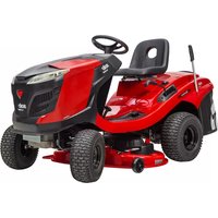
Download the instructions for your Tractor in PDF format for free! Find your manual T 1695.6 HD V2 - SOLO and take your electronic device back in hand. On this page are published all the documents necessary for the use of your device. T 1695.6 HD V2 by SOLO.
USER MANUAL T 1695.6 HD V2 SOLO
AL-KO KOBER GROUP Kottz, Germany
This documentation or excerpts therefrom may not be reproduced or disclosed to third parties without the express permission of the AL-KO KOBER GROUP.

1 About these instructions for use 31
1.1 Symbols on the title page 31
1.2 Legends and signal words 31
2 Product description 31
2.1 Designated use 31
2.2 Possible misuse 31
2.3 Symbols on the appliance 32
2.4 Safety and protective devices 32
2.5 Product overview (01) 32
3 Safety instructions 32
4 Unpacking and assembling the tractor .... 33
5 Controls 33
5.1 Standard dashboard (02) 33
5.2 Dashboard with display (03) 33
5.2.1 Function keys and display 34
5.2.2 Pilot lights 34
5.3 Brake and clutch pedal (05) 35
5.4 Transmission operation (driving speed) (04) 35
5.5 Foot hydrostat transmission (04, 05).. 35
5.6 Operating the mower mechanism (06) 35
6 Start-up 35
6.1 Checking the mower mechanism 36
6.2 Oil fill 36
6.3 Filling with fuel (09) 36
6.4 Checking the tyre pressure 36
6.5 Fitting the grass catcher (10 - 13) .... 36
6.6 Checking the safety devices 37
6.6.1 Checking the brake contact switch 37
6.6.2 Checking the mower mechanism contact switch 37
6.6.3 Checking the seat contact switch 37
6.6.4 Checking the grass catcher contact switch 37
6.6.5 Checking the discharge channel contact switch 37
7 Operating the tractor 37
7.1 Fundamental preparatory measures.. 37
7.2 Use of accessories 38
7.3 Pushing the lawn tractor (15, 16) 38
7.4 Starting and stopping the engine.... 38
7.5 Driving with the tractor 38
7.5.1 Preparing to drive at temperatures below 10^ 38
7.5.2 Driving with the foot hydrostat transmission 39
7.5.3 Driving with cruise control 39
7.5.4 Driving and mowing on slopes 39
7.5.5 Mowing with the lawn tractor.... 39
8 Cleaning the lawn tractor. 41
8.1 Cleaning the grass catcher 41
8.2 Cleaning the deck, engine and transmission 41
8.3 Cleaning the discharge channel (18)... 41
9 Maintenance. 42
9.1 Maintenance schedule 42
9.2 Lubricating plan 42
9.3 Wheel change 43
9.4 Starter battery 43
9.5 Removing the mower mechanism 44
9.6 Renewing the V-belt 44
10 Transport. 44
11 Storage 44
12 Help in case of malfunction 45
12.1 Fault and fault rectification error shown on display 47
13 Guarantee 49
1 ABOUT THESE INSTRUCTIONS FOR USE
The German version is the original operating instructions. All additional language versions are translations of the original operating instructions.
Always safeguard these operating instructions so that they can be consulted if you need any information about the appliance.
Only pass on the appliance to other persons together with these operating instructions.
Comply with the safety and warning information in these operating instructions.
The lawn tractors are supplied with different levels of equipment. Please note that the illustrations may differ somewhat from the original. Please contact a specialist workshop or the manufacturer if you encounter difficulties in following the descriptions.
Comply with the enclosed installation instructions and the operating instructions for the petrol engine.
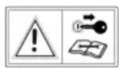
1.1 Symbols on the title page
Symbol Meaning

It is essential to read through these operating instructions carefully before start-up. This is essential for safe working and trouble-free handling.

Operating instructions
Never operate the petrol powered device in the vicinity of open flames or heat sources.
1.2 Legends and signal words
DANGER! Denotes an imminently dangerous situation which will result in fatal or serious injury if not avoided.
WARNING! Denotes a potentially dangerous situation which can result in fatal or serious injury if not avoided.
CAUTION! Denotes a potentially dangerous situation which can result in minor or moderate injury if not avoided.
IMPORTANT! Denotes a situation which can result in material damage if not avoided.
NOTE Special instructions for ease of understanding and handling.
2 PRODUCT DESCRIPTION
Lawn tractors with rear discharge are manufactured in different versions. When reading the following descriptions in these instructions for use, make sure you are referring to the appropriate description for your lawn tractor.
Features of your lawn tractor:
Transmission: Foot hydrostat
Blade brake clutch: electromagnetic
Grass catcher capacity: 310 l
Grass catcher emptying: electric, telescopic lever
There are also differences in mulch systems, engine types, engine power and cutting width.
Type differences:
Cutting width
Transmission type (T3 and G700)
Transmission bypass release
2.1 Designated use
The lawn tractor is intended for mowing in domestic gardens and allotments with a max. slope of 10^ (18%) . Additional applications, such as for mulching, are only permitted if the original accessories are used and in compliance with the maximum load values.
This appliance is intended solely for use in non-commercial applications. Any other use (as well as unauthorised conversions or add-ons) are regarded as contrary to the intended use and will result in exclusion of the warranty as well as loss of conformity (CE mark); the manufacturer will thus decline any responsibility for damage and/or injury suffered by the user or third parties.
2.2 Possible misuse
The lawn tractor is not designed for commercial use in public parks, sports grounds, agriculture and forestry.
WARNING! Dangers due to overloading the lawn tractor! In particular, when using a trailer make sure not to exceed the permitted pulling forces and uphill/downhill gradients. Exceeding these values may exceed the braking capacity of the lawn tractor and lead to dangerous situations!
NOTE Bear in mind that the lawn tractor does not have approval for road use, and thus is not allowed to be driven on public roads!
2.3 Symbols on the appliance

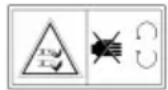
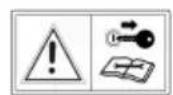
Before starting operation, read the operating instructions.
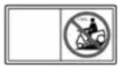
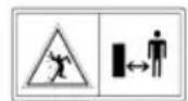
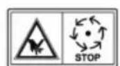
Keep other people, especially children and animals, out of the working area during mowing.
Remove the ignition key before maintenance and repair work!
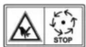
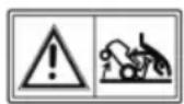
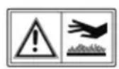
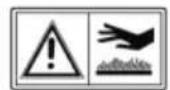
Important - danger! Keep your hands and feet away from the blade system.
Do not drive on gradients of more than 10^ (18%)
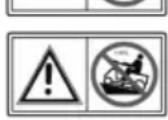
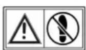
Danger: Do not step here!
Risk of burns on hot surfaces!

2.4 Safety and protective devices
WARNING! Danger if protective devices are removed or manipulated! Do not operate with any protective devices removed or manipulated. Defective protective devices must be repaired or renewed immediately!
Above all, the protective devices include:
Brake contact switch
Mower mechanism contact switch
Grass catcher contact switch
Seat contact switch
Mower mechanism covers
Discharge channel contact switch
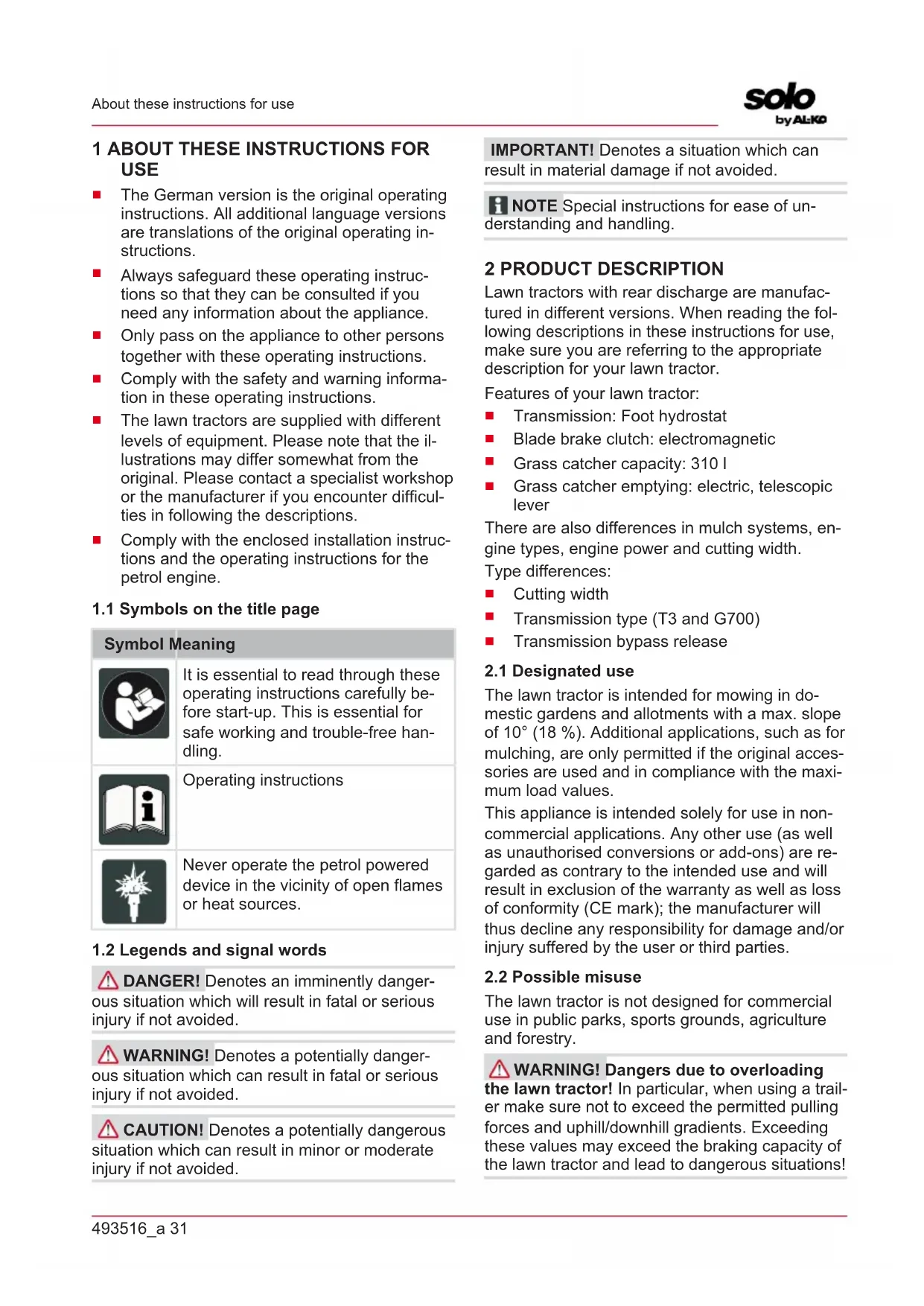
2.5 Product overview (01)
No. Component
1 Steering wheel
2 Dashboard
3 Brake pedal
4 Engine cover
5 Transmission activation reverse
6 Transmission activation forwards
7 Mower mechanism
8 Cutting height adjustment
9 Transmission bypass
10 Grass catcher sensor
11 Grass catcher operation
12 Grass catcher
13 Operator's seat
14 Electric grass catcher operation
15 Locking lever for brake pedal
16 Cruise control lever
- Configuration varies and depends on model
3 SAFETY INSTRUCTIONS
Children, or other people who are not familiar with the instructions for use, are not allowed to use the equipment.
Comply with local regulations on the minimum age of people operating the equipment.
Do not allow children and young people to play on the machine.
Only mow during daylight hours or with good artificial lighting.
- Keep other people out of the danger area.
The user is responsible for accidents involving other people and their property.
Only use genuine spare parts and genuine accessories.
Repairs to the machine must be carried out by the manufacturer or by one of its customer service centres.
Wear hearing protection.
The lawn tractor does not have approval for road use and may not be driven on public roads.
- Do not mow during thunderstorms. No protection against lightning strikes.
Do not carry any passengers on the machine.
Do not mow on slopes with more than 10^ (18%) gradient
- Do not work with the lawn tractor and/or with accessories attached to it after you have consumed alcohol, medicines which impair reactions, or drugs.
Always mow across the slope.
Comply with the permitted operating times in your vicinity.
The lawn tractor can cause serious injuries due to its inherent weight. Take particular care when loading and unloading the lawn tractor before/after transport on a vehicle or trailer.
This lawn tractor is not allowed to be towed. Use a suitable vehicle for transport on public roads.
- Do not operate the lawn tractor in poorly ventilated working areas (e.g. a garage). The exhaust gases contain poisonous carbon monoxide as well as other harmful substances.
4 UNPACKING AND ASSEMBLING THE TRACTOR
Comply with the supplied assembly instructions for unpacking and assembling the tractor.
NOTE Also comply with the enclosed operating instructions for the petrol engine.
WARNING! Danger if assembly is not carried out completely! Do not operate the lawn tractor before it has been fully assembled! Carry out all the work described in the assembly instructions. If you are uncertain about anything, ask a specialist to confirm that the assembly has been carried out correctly before the machine is started up! Check whether all safety and protective devices are in place and functioning correctly!
5 CONTROLS
The following section describes the controls of lawn tractors with rear discharge. Make sure you
are referring to the appropriate description for your lawn tractor.
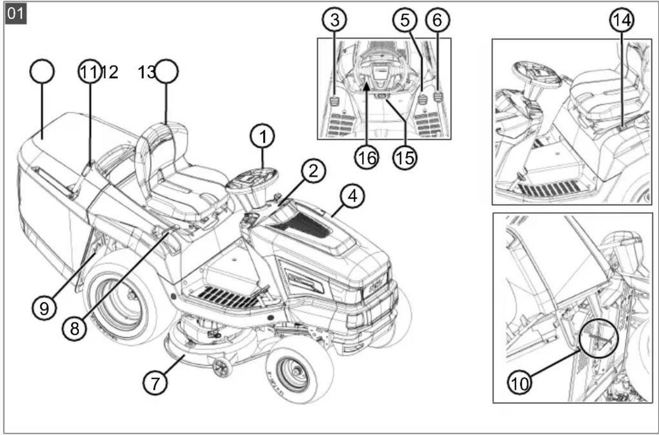
5.1 Standard dashboard (02)
The elements of the standard dashboard are explained below.
Controlling the engine speed
NOTE Please note that operating the controller while driving influences the speed!
For controller with integrated choke:
Moving the controller (02/2) increases or decreases the engine speed. The choke is activated in the highest position.

Switch on the choke: Push the controller all the way towards the choke symbol. Only use this position for starting the engine.
Note: Some tractor variants have a separate choke knob (02/1) on the dashboard. This must be pulled out as well in order to start the tractor. When the engine is running, slowly push the button back in!

Mowing: In this position, the engine runs at maximum speed.

Idling: In this position, the engine runs at the lowest speed.
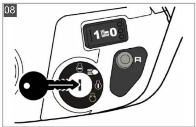
Ignition lock (02/4)
| Position | Function |
| 0 | Engine off. |
| The ignition key can be removed. | |
| I | Headlights on. |
| The headlights are switched on in this position after the engine has started. | |
| II | Operating position when the engine is running. |
| III | Start position for starting the engine. |
| Release the key as soon as the engine is running. Then it springs back to operating position II. |
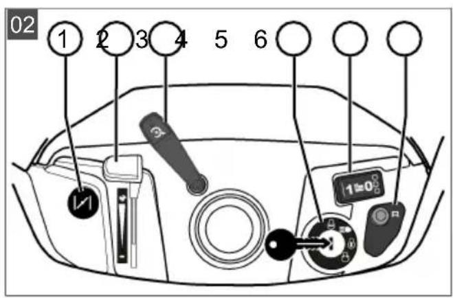
5.2 Dashboard with display (03)
Read this chapter if your lawn tractor has a display above the standard dashboard.
5.2.1 Function keys and display
| Item Designation Function | |
| 03/2 The display shows the following: ■ Daily operating hours (indicated to one decimal place) Note: The daily operating hours are indicated using the decimal system (1.5 h = 1 h 30 min). or ■ Total operating hours (indicated without decimal place) Note: The total operating hours start counting as soon as the ignition key is turned to position I. | |
| 03/5 To change over the display: ■ Total operating hours ■ Daily operating hours ■ Battery voltage Note: Counting of the total operating hours continues if the ignition key is left in the ignition lock in position "I". | |
| 03/13 Resetting the daily operating hours to “0”. ■ Note: Only the daily operating hours can be reset to “0”, not the total operating hours. |
5.2.2 Pilot lights
| Item Designation The display lights up: | ||
| 03/1 | ■ With the engine running: ■ With the starter battery defective or flat. ■ Discontinuity in the cable line from the engine to the battery. ■ Fuse blown (15 A blue). ■ Alternator on engine defective. ■ With the engine stopped: ■ With the starter battery exhaustively discharged. Note: Contact the specialist workshop if this display lights up! | |
| 03/3 If the grass catcher is full. | Empty the grass catcher! | |
| 03/4 If the mower mechanism is switched on. | ||
| 03/6 If operation of the mower mechanism is permitted in reverse. | ||
| 03/7 With the grass catcher removed or not correctly closed. | ||
Item Designation The display lights up:
03/8 With the headlights switched on.

03/9 If the brake is applied and with the brake locked.

03/10 When there are only about 1.5 litres of fuel remaining in the tank.
03/11 If the oil levels below a particular level.

03/12 If the operator gets off the tractor with:
engine running (brake is locked)
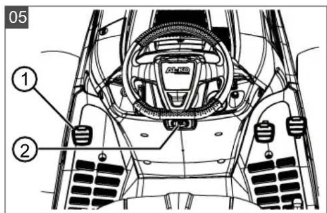
5.3 Brake and clutch pedal (05)
- Brake: Pressing the brake pedal (05/1) all the way down operates the brake on the transmission and the tractor is braked.
- Parking brake: Pulling the parking brake lever (05/2) upwards while the brake pedal (05/1) is pressed down engages the parking brake. Pressing the brake pedal again releases the parking brake.
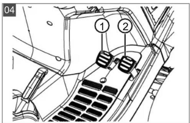
5.4 Transmission operation (driving speed) (04)
Lawn tractors are equipped with a foot hydrostat transmission.
Some models are equipped with cruise control.
There are two separate pedals on the right for driving forwards and in reverse.
Direction Description of travel
Forwards Press the right pedal (04/2) to drive forwards.
Reverse Press the left pedal (04/1) to drive in reverse.
Note: The mower mechanism is switched off if just the reverse pedal is pressed.
Mowing in reverse: see chapter 7.5.5 "Mowing with the lawn tractor", page 39.
5.5 Foot hydrostat transmission (04, 05)
The foot hydrostat transmission is operated by two pedals (04/1 and 04/2).
To move off, first release the parking brake (05/2) while the engine is running and then press pedal (04/2) to drive forwards or pedal (04/1) to reverse. The further you press the pedal, the faster your speed will be in the selected direction.
Forward travel: Press the outer pedal (04/2) on the right side.
Reverse travel: Press the inner pedal (04/1) on the right side.
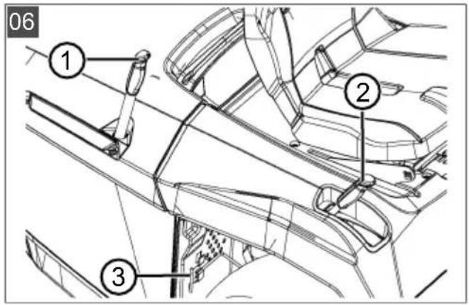
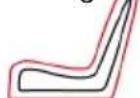
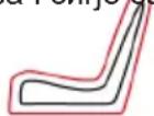
5.6 Operating the mower mechanism (06)
Setting the cutting height
The mower mechanism of the tractor can be set to various different heights using a lever (06/2) on the right next to the operator's seat.
- Move the adjusting lever (06/2) in the desired direction. When the lever is down, the cutting height is low; when the lever is up, the cutting height is high.
Switching on the mower mechanism
Switching on electrically: There is a switch (02/5) in the area of the dashboard. Use this to switch the mower mechanism on (i.e. to position "1").
6 START-UP
WARNING! Danger if assembly is not carried out completely! Do not operate the lawn tractor before it has been fully assembled! Carry out all the work described in the assembly in
structions. If you are uncertain about anything, ask a specialist to confirm that the assembly has been carried out correctly before the machine is started up! Check whether all safety and protective devices are in place and functioning correctly!
6.1 Checking the mower mechanism
Before use, always look and check whether the cutter, fastening pin and the entire mowing unit are worn or damaged. Worn or damaged blades must be renewed by new ones in order to avoid any imbalance.
6.2 Oil fill
The engine must be filled with oil before initial start-up. Please comply with the instructions from the engine manufacturer in this regard. Also make sure the oil level is checked at regular intervals and the oil is topped up if necessary.
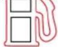
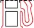
6.3 Filling with fuel (09)
WARNING! Dangers when handling fuel!
Fuel is highly inflammable. Only fill the fuel tank outdoors! Do not smoke! Do not refuel when the engine is running or is hot!
Use a suitable funnel or a filler pipe when refuelling so that no fuel is spilled on the engine, the deck or the ground.
For safety reasons, the fuel tank cap and other tank caps must be renewed if damaged.
Do not start the engine if the fuel has overflowed.
The tractor must be removed from the area contaminated by fuel, and the spilled fuel must be absorbed and wiped away from the ground, the engine and the deck using a cloth.
Do not make any attempt to start the machine until fuel vapours have evaporated.
Only keep the fuel in containers intended for this purpose.
Use lead-free petrol, min. RON 91.
Filling the tank
- Switch off the engine if it is running and remove the ignition key as a precaution.
- Wait until the engine has cooled down somewhat (risk of explosion if the fuel catches fire!).
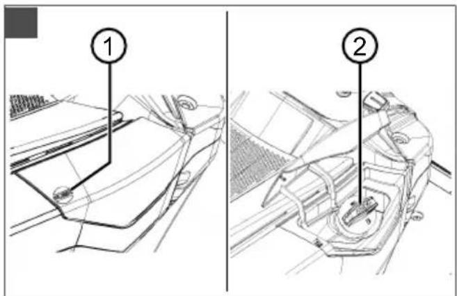
- Press on the tank cap cover (09/1).
-
Swivel the tank cap cover (09/1) upwards. The tank cap cover (09/1) is unlocked.
-
Open the tank cap (09/2) and pour in the fuel. Note: Avoid overfilling the fuel tank!
- Close the tank cap (09/2).
- Close the tank cap cover (09/1) so it engages.
6.4 Checking the tyre pressure
Check the tyre pressure at regular intervals.
Please refer to the specification on the tyre for the necessary inflation pressure (recommendation: 1 bar).
NOTE 1 PSI = 0.07 bar.
The tyre pressure can be checked and the tyre inflated using a commercially available foot pump.
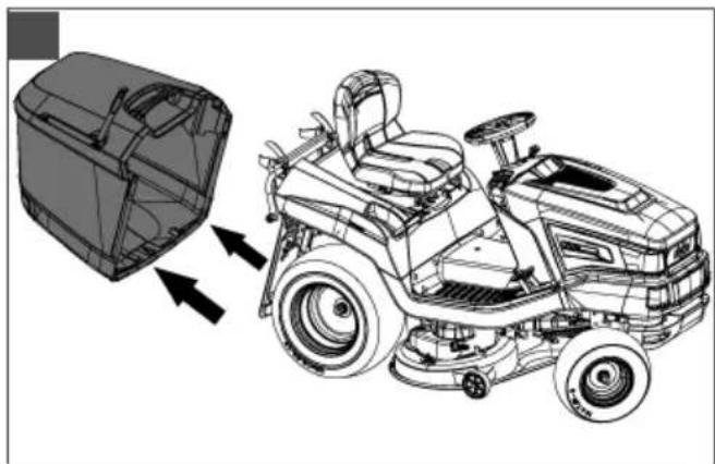
6.5 Fitting the grass catcher (10 - 13)
Lawn tractors are supplied with a grass catcher. Please note that the illustrations may differ somewhat from the original.
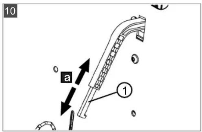
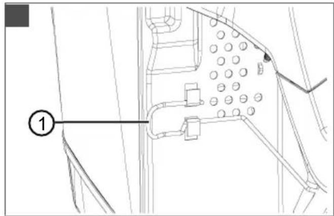
Adjusting the fill-level sensor of the grass catcher
The fill-level sensor uses a horn to signal when the grass catcher must be emptied.
The fill-level sensor can be set to 6 positions, depending on the condition of the cut grass. With dry grass, push the fill-level sensor to the smaller positions. With wet or damp grass, set the fill-level sensor to the higher positions. This influences the filling of the grass catcher.
- Shut off the engine (see chapter 7.4 "Starting and stopping the engine", page 38).
- Remove the grass catcher (see chapter 8.1 "Cleaning the grass catcher", page 41).
- Adjust the fill-level sensor (10/1) to suit the grass to be cut (10/a) until it engages in the desired position.
- Hook in the grass catcher again.
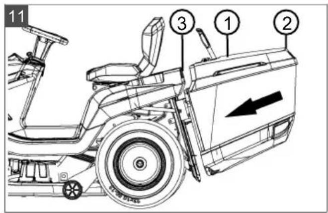
Hooking in the grass catcher
- Hold the grass catcher with one hand on the catcher handle (11/1) and the other hand on the holding opening at the back (11/2).
- Place the grass catcher symmetrically onto the guide (11/3).
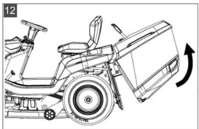
- Use your other hand to tip the grass catcher slightly forward (12) so the front part of the grass catcher engages.
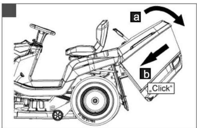
- Now swivel the grass catcher back down (13/a).
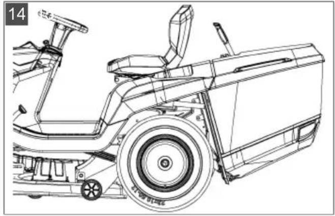
- Check the grass catcher is correctly seated.
6.6 Checking the safety devices
Check the safety devices each time before the lawn tractor is started.
WARNING! Danger when checking the safety devices! The safety devices are only allowed to be checked from the driver's seat, and when no other persons or animals are in the vicinity!
Carry out all checks on level ground so that the lawn tractor cannot roll away inadvertently.
6.6.1 Checking the brake contact switch
The brake contact switch ensures that the engine cannot be started if the brake is not applied.
- The engine is off.
- Sit on the operator's seat.
- Release the parking brake by pressing the brake pedal (05/1).
- Attempt to start the engine (ignition key in position III).

NOTE The engine is not allowed to start!
6.6.2 Checking the mower mechanism contact switch
The mower mechanism contact switch ensures that the engine cannot be started if the mower mechanism is activated.
- The engine is off.
- Sit on the operator's seat.
- Press the brake pedal (05/1) and the parking brake (05/2).
- Switch on the mower mechanism (02/5, position "1").
- Attempt to start the engine (ignition key in position III).

NOTE The engine is not allowed to start!
6.6.3 Checking the seat contact switch
The seat contact switch ensures that the engine switches off as soon as there is no-one on the operator's seat when the mower mechanism is switched on.
- Sit on the operator's seat.
- Press the brake pedal (05/1) and the parking brake (05/2).
- Start the engine and let it run at maximum rpm.
-
Switch on the mower mechanism (02/5, position "1").
-
Take your weight off the seat by standing up (do not get off!).

NOTE The engine must switch itself off!
6.6.4 Checking the grass catcher contact switch
The grass catcher contact switch ensures that the engine is switched off as soon as the grass catcher is no longer hooked in correctly when the mower mechanism is switched on.
- Sit on the operator's seat.
- Press the brake pedal (05/1) and the parking brake (05/2).
- Start the engine and let it run at maximum rpm.
- Switch on the mower mechanism (02/5, position "1").
- Lift the empty grass catcher slightly, or press the opening switch.

NOTE The engine must switch itself off!
6.6.5 Checking the discharge channel contact switch
The discharge channel contact switch ensures that the lawn tractor cannot be started when the discharge channel is removed.
- Remove the grass catcher.
- Remove the discharge channel (18/2).
- Sit on the operator's seat.
- Press the brake pedal (05/1) and the parking brake (05/2).
- Start the engine.

NOTE The engine is not allowed to start!
WARNING! Dangers due to inadequate knowledge of the lawn tractor! Read the operating instructions for use carefully before you start! Pay particular attention to all safety instructions! Carry out all assembly and start-up work conscientiously. Ask the manufacturer if you have any doubts!
7.1 Fundamental preparatory measures
Always wear tough shoes and long trousers while mowing. Never mow barefoot or when wearing open sandals.
Check the complete area on which the lawn tractor is to be used. Remove all stones,
sticks, wires, bones and other foreign objects which could be scooped up and flung out. Also pay attention to foreign objects during mowing.
- Carry out all the work described in the startup instructions. This applies in particular to checking the safety devices.
Only use the towing hitch for pulling loads! Do not exceed the imposed load limit.
Do not transport objects on the lawn tractor!
7.2 Use of accessories
WARNING! Danger due to incorrect accessories or incorrect use of accessories! Only ever use genuine accessories from the tractor manufacturer! Pay attention to the regulations on use in the supplied operating instructions!
Using unauthorised accessories, or using accessories incorrectly, can expose the operator and other persons to significant risks. The lawn tractor could be overloaded. This can lead to serious accidents.
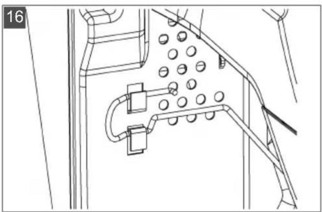
7.3 Pushing the lawn tractor (15, 16)
CAUTION! Danger when pushing on slopes! Only push the lawn tractor on level ground! On slopes, the lawn tractor could roll downhill uncontrollably.
For a foot hydrostatic drive
The bypass lever (15/1) is located in the rear right wheel housing.
Bypass unlocking on T3 transmission (type: T15, T16, T18):
- Pull out the bypass lever (15/1) and hook it in place upwards (16).
- Release the brake.
The lawn tractor can now be pushed.
Bypass unlocking on G700 transmission (type: T20, T23):
- Push in the bypass lever (15/1) and hook it in place upwards (16).
- Release the brake.
The lawn tractor can now be pushed.
7.4 Starting and stopping the engine
Starting the engine
- Sit on the operator's seat.
-
Press the brake pedal (05/1) on the left side down fully and lock it using the locking lever (05/2).
-
Make sure the mower mechanism is not switched on. To do this, check the position of the toggle switch (02/5, position "0").
- Move the engine speed controller (02/2) to the top end stop. The choke symbol is located there, depending on the equipment variant. If it is not, pull the separate choke knob (02/1).
- Insert the ignition key into the ignition lock (02/4).
- Turn the ignition key to position "III" and hold it there until the engine is running. Note: To reduce strain on the starter battery, do not attempt to start for any longer than about 5 seconds.
- Then release the ignition key, it automatically jumps to position "I".
- Move the engine speed controller (02/2) to the operating position. In an equipment variant with the choke knob, press it back in again (02/1).
Switch off the engine
- Switch off the mower mechanism (02/5).
- Move the controller (02/2) for the engine speed to the idling speed position.
- Press the brake pedal (05/1) and lock it using the locking lever (05/2).
-
Turn the ignition key (02/4) to the "0" position.
-
Remove the ignition key.
WARNING! Danger if the engine is hot! When stopping the engine, ensure that hot engine components such as the silencer cannot set fire to objects or materials located nearby!
7.5 Driving with the tractor
WARNING! Danger in case of inappropriate speed! Drive slowly, especially at the beginning, in order to familiarise yourself with the driving and braking properties of the tractor! Before each change of direction, adjust the driving speed so as to retain control of the lawn tractor at all times, and to prevent it from tipping over!
Your tractor is driven via a foot hydrostat transmission.
7.5.1 Preparing to drive at temperatures below 10^
-
Make sure the mower mechanism is not switched on. To do this, check the position of the toggle switch (02/5, position "0").
-
Start the engine and let it run for about 30 seconds to warm up and optimise the gear oil viscosity. Following that, you can drive the tractor. Do not switch on the mower mechanism until the engine has been running for a few minutes.
7.5.2 Driving with the foot hydrostat transmission
- Press the brake pedal (05/1) and lock it using the locking lever (05/2).
- Set the mower mechanism to the maximum cutting height (06/2).
- Start the engine.
- Press the brake (05/1).
- Slowly press the foot pedal for the required driving direction:
Forwards: Foot pedal (04/2)
Reverse: Foot pedal (04/1)
- The further you press the pedal, the faster the tractor will drive in the selected direction.
- To stop, release the foot pedal and press the brake (05/1).
NOTE When you leave the tractor, always activate the locking lever when the brake pedal is pressed, to prevent the tractor from rolling away!
7.5.3 Driving with cruise control
NOTE The cruise control can only be switched on when driving forwards. Pressing the brake automatically switches the cruise control off.
Switching the cruise control on/off:
Pivot lever (02/3) upwards. The cruise control is switched on.
Pivot lever (02/3) downwards. The cruise control is switched off.
7.5.4 Driving and mowing on slopes
WARNING! Danger due to mistakes when driving on slopes! Be particularly careful when driving on slopes! There is no such thing as a "safe" slope. In particular, comply with the following safety instructions here! Disengage the mower mechanism and add-on devices if the wheels spin or the vehicle stalls when driving on a slope. Then drive away down the slope slowly, straight along the fall line! The weight of a full grass catcher increases the risk of the lawn tractor tipping over!
- Do not drive on gradients of more than 10^ (18%) . Example: This corresponds to a change of 18~cm in height over a distance of 1 metre.
Drive smoothly.
Do not brake suddenly. - Keep the driving speed low.
Do not drive across the slope.
Do not accelerate suddenly.
Steer smoothly.
7.5.5 Mowing with the lawn tractor
Adapt the driving speed to the conditions of the lawn in order to achieve a tidy mowing result. Select at most two thirds of the possible driving speed at the pedal when mowing. The maximum speed of the tractor is exclusively intended for driving without the mower mechanism switched on.
Normally, the cutting height is 4 - 5cm . This corresponds to the 2nd or 3rd detent of the height adjustment (06/2). Mow with a higher cutting height if the grass is moist or wet.
If the grass is very long, it is a good idea to mow in two passes. Set the mower mechanism to the maximum cutting height on the first pass. You can reduce it to the required height for the second pass.
7.5.5.1 Switching on the mower mechanism
NOTE Do not switch on the mower mechanism until the engine has been running for about one minute to warm up! The lawnmower should not be standing in tall grass when the mower mechanism is engaged.
- Start the engine.
- Move the engine speed controller (02/2) to the operating position.
- Set the mower mechanism to the maximum cutting height (06/2).
- Engage the mower mechanism using the toggle switch (02/5, position "1").
- Set the required cutting height using the hand lever (06/2).
- Set the lawn tractor in motion.
7.5.5.2 Mowing in reverse
NOTE The mower mechanism is switched off if just the reverse transmission pedal is pressed.
- Press the "Reverse mowing" button (02/6) and, within 5 seconds, press the pedal for reverse driving (04/1).
WARNING! There is an accident risk when reverse mowing! Pay attention to the area behind you when mowing in reverse! Only mow in reverse when it is necessary to do so!
7.5.5.3 Switching off the mower mechanism
WARNING! Danger due to spinning blades! When the cutting blades are still spinning, they can cause laceration injuries to hands and feet! As a result, keep your hands and feet away from the cutters!
- Disengage the mower mechanism using the toggle switch (02/5, position "0").
The mower mechanism can be switched off when the tractor is at a standstill and when it is being driven.
WARNING! Risk of injury due to objects being thrown out! When crossing areas of gravel and crushed stone, objects can be drawn into the running mower mechanism and then thrown out.
Always switch off the mower mechanism if you are driving over surfaces other than lawns.
7.5.5.4 Emptying the grass catcher
NOTE An audible signal sounds when the grass catcher is full. The catcher should be emptied now if not before.
Depending on the equipment variant, your lawn tractor has electrically operated grass catcher emptying or a manually operated grass catcher with operating lever.
The following applies to all catcher types:
The grass catcher can be emptied from the operator's seat.
The engine cuts out if the grass catcher is lifted up or disconnected when the mower mechanism is switched on.
The mower mechanism cannot be switched on unless the grass catcher is engaged correctly.
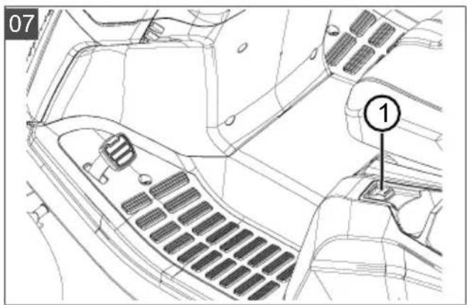
Emptying the electrically operated grass catcher
-
For emptying, operate the toggle switch (07/1) on the left of the operator's seat.
-
To close the grass catcher, operate the toggle switch again.
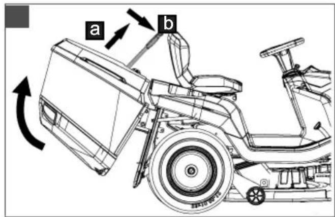
Emptying the grass catcher with operating lever
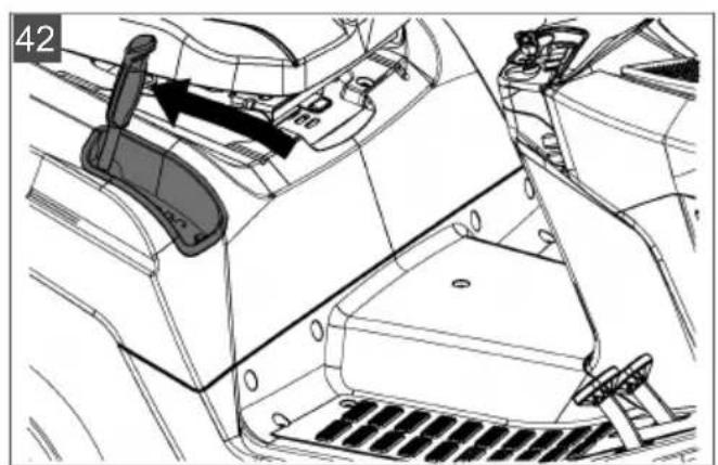
- Pull the operating lever out of the grass catcher (17/a).
- Push the lever in the driving direction so the grass catcher opens (17/b).
- Move the grass catcher backwards with the lever until the catcher engages.
7.5.5.5 Mulching
For optimum mulching results, the grass should be mowed on a regular basis (approx. 1 or 2 times per week). When doing so, cut 1/3 of the grass height (e.g. if grass height is 6cm ,mow 2cm) . This will ensure that the mown grass will be properly intermixed in the remaining grass.
7.5.5.6 Mowing interval
Please take into account that grass grows differently at different times. We recommend using a shorter interval between mowing during early spring. You can increase the mowing intervals as the growth rate of the grass begins to decline during the course of the year.
If you are unable to mow the grass for an extended period, you should initially select a higher cutting height setting, then re-mow two days later with a lower cutting height setting.
7.5.5.7 Mowing high grass
Mow with a higher cutting height adjustment when the grass is longer than normal or when it is wet. Then re-mow the grass with a lower, normal setting.
7.5.5.8 Cutting blade maintenance
Make sure that the cutting blade remains sharp for the entire mowing season to avoid shredding or tearing the blades of grass. Shredded grass blades turn brown on the edges. This reduces their growth and leaves the lawn prone to diseases.
Check the cutting blade for sharpness and signs of wear or damage after each use! If necessary please contact a service workshop.
If replacement is required, only use original manufacturer replacement blades.
8 CLEANING THE LAWN TRACTOR
The lawn tractor must be cleaned regularly to ensure optimum function and a long service life.
Clean the lawn tractor after each use to remove adhering dirt and detritus.
Do not use a high-pressure cleaner for cleaning.
The water jet from a high-pressure cleaner or a garden hose can damage the electrical system or bearings.
In particular, make sure that no water comes into contact with the engine, transmission and deflection pulleys, as well as the entire electrical system.

WARNING! Dangers when cleaning!
During all cleaning work:
Switch off the engine and remove the ignition key.
Remove the spark plug connector.
Protective devices removed for cleaning must be reinstalled afterwards.
DANGER OF BURNS: Do not clean the lawn tractor until it has cooled down. The engine, transmission and silencer get very hot!
DANGER OF LACERATIONS: When working on the cutters, pay attention to the sharp blades. In mowers with more than one blade, moving one cutter can cause the other to move as well!
8.1 Cleaning the grass catcher
To do this, remove the grass catcher and clean it by spraying inside and out with a water hose. Firmly adhering contamination must be scraped off carefully, such as by using a brush. Especially in grass catchers with a fabric covering, take care not to damage the fabric.
NOTE Empty the grass catcher before cleaning as described. A full grass catcher is too heavy to be removed safely.
Removing a grass catcher
- Switch off the engine.
- Tilt the grass catcher slightly.
- Remove the grass catcher upwards.
Removing an electrically operated grass catcher
- Switch off the engine.
- Make sure that the electrically operated grass catcher is closed.
- Tilt the grass catcher (approx. 30^ ).
- Remove the grass catcher upwards.
8.2 Cleaning the deck, engine and transmission
IMPORTANT! Damage to the electrical system by penetrating water! Take care when cleaning the tractor with water to ensure that no water gets into the electrical system!
Do not use water or a high-pressure cleaner to spray down the engine or any of the bearing points (wheels, transmission, blade bearing).
Water penetrating the ignition system, carburettor and air filter can cause malfunctions. Water in the bearing points can lead to loss of lubrication, and thus cause irreparable damage to the bearings.
Use a cloth, hand brush, long-handled paintbrush or similar for removing dirt and grass residues.
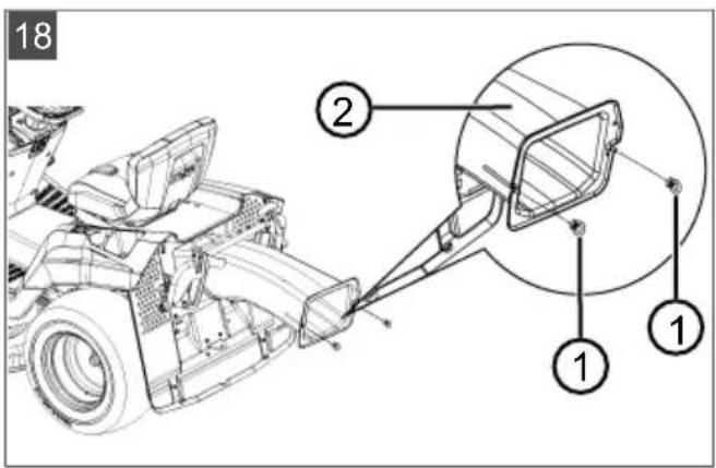
8.3 Cleaning the discharge channel (18)
Regular cleaning ensures that the cutting height adjustment can be moved easily.
The discharge channel consists of two parts pushed one inside the other. The lower part is firmly engaged in the lower deck. The upper part can be pulled out for cleaning.
- Remove the grass catcher.
- Remove the screws (18/1) on the left and right of the discharge channel (18/2).
- Pull the discharge channel through the back wall and out to the rear.
- Thoroughly clean the upper and lower discharge channel.
- Insert the discharge channel into the back wall. When doing this, make sure that the upper and lower parts fit cleanly one inside the other.
- Screw it on tight using the two fastening screws.
- Mount the grass catcher.
9 MAINTENANCE

WARNING! Dangers during maintenance!
During all maintenance work:
- Switch off the engine and remove the ignition key.
Remove the spark plug connector.
Protective devices removed for maintenance must be reinstalled afterwards.
DANGER OF BURNS: Do not work on the lawn tractor until it has cooled down. The engine, transmission and silencer get very hot!
DANGER OF LACERATIONS: When working on the cutters, pay attention to the sharp blades. In case of mowers with multiple blades, moving one cutter can cause another one to move as well.
Parts are only allowed to be renewed by genuine spare parts.
If in doubt, always visit a specialist workshop or contact the manufacturer.
9.1 Maintenance schedule
The following jobs are allowed to be carried out by the user independently. All other maintenance, service and repair work must be carried out in an authorised service workshop.
NOTE It may be necessary to shorten the maintenance intervals compared to those stated in the table above in case of severe loading and at high temperatures.
In addition, please also comply with the recommended annual lubrication tasks as indicated in the lubrication plan.
| Activity Before | each use | After each use | After the first 5 hours | Every 25 operating hours | Every 50 operating hours | Each time be- fore putting into storage |
| Check the engine oil level* | X | |||||
| Change the engine oil* | X | X | ||||
| Clean the air filter* | X | |||||
| Replace the air filter* | X | |||||
| Check the spark plug* | X | |||||
| Check the brake (test braking on a straight path) | X | |||||
| Check the tyre pressure X | ||||||
| Check the mowing blades X | ||||||
| Check for loose parts XX | ||||||
| Check V-belts (visual check) X | ||||||
| Clean the lawn tractor X | ||||||
| Clean the air intake grille on the engine* | X | |||||
| Clean the transmission to remove grass and mowing residues | X | X |
*) Refer to the operating instructions of the engine manufacturer
9.2 Lubricating plan
To ensure that moving parts can move freely, we recommend lubricating the following points at least once a year.
Use a cloth to clean all points to be lubricated before greasing or spraying. Do not use water, so as to avoid possible corrosion.
Lubrication points:
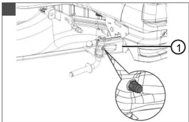
Grease the grease nipples on the right and left steering knuckles (21) using multi-purpose grease.
Spray oil onto the bearings of the front axle on the frame (21/1).
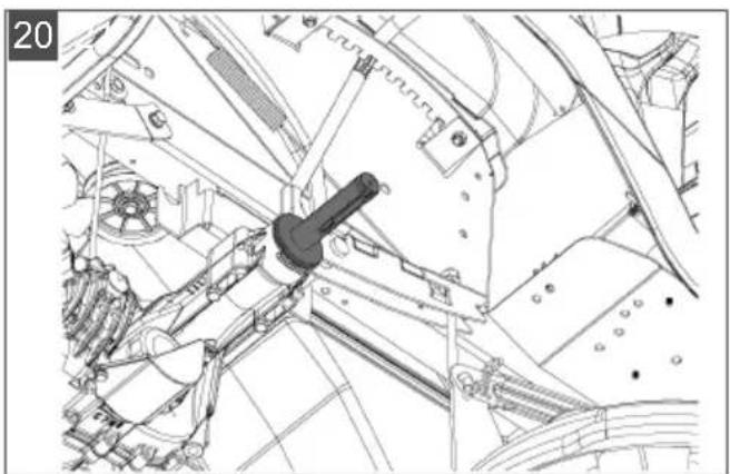
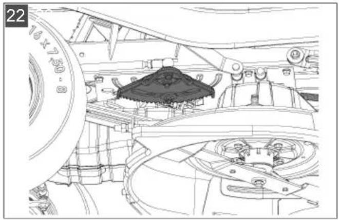
Grease the toothed segments and steering pinion on the steering box (22) using multipurpose grease.
Grease the roller bearings and hub on the front and rear axles (23 / 20) with multi-purpose grease.
NOTE The front and rear wheels must be removed for greasing the axles and bearings.
Pivoting and bearing points: Lubricate all movable pivoting and bearing points.
9.3 Wheel change
Wheel changes are only allowed to be carried out on firm, level ground.
- Park the lawn tractor and remove the ignition key.
- Press the brake pedal (05/1) fully and lock it using the locking lever (05/2).
- Secure the lawn tractor with chocks to prevent it from rolling away. Place the chocks under the side that is not being raised.
- Use suitable lifting gear (e.g. a scissor jack) to lift the lawn tractor on the side where the wheel should be changed. Lift the tractor until the wheel to be changed can turn freely. Important! Danger of damage to the device!
Take care not to bend any tractor elements when lifting. Only position the jack on sturdy metal components.
- Secure the lawn tractor by placing a sturdy support (e.g. a wooden block) under a supporting part of the chassis so that it cannot drop down even if the jack were to slip or tip over.
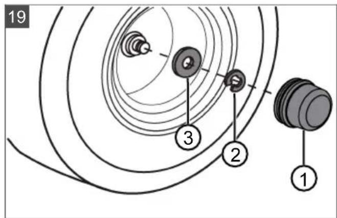
- Pull off the protective cap (19/1).
- Use a screwdriver to press out the lock washer (19/2). Make sure not to lose the parts.
8.Pull off the plain washer (19/3). - Pull the wheel off the axle.
Note: Do not lose the feather key when pulling the rear wheels off the axle!
- Clean the axle and the hole in the wheel before reassembly, and grease both of them with multi-purpose grease.
- Put the wheel onto the axle. Note: When pushing on the rear wheels, make sure that the grooves for the feather key and the rear wheel are aligned so that the feather key can be pushed in without force.
- Put the washer onto the axle.
- Push the lock washer into the groove on the axle. If you use a pair of pliers to do this, take care not to damage the axle using the pliers.
- Put the protective cap onto the axle.
- Remove the securing support and use the jack to lower the tractor carefully down to the ground.
9.4 Starter battery
No charger is supplied for the starter battery of the lawn tractor.
Precise battery designation: see battery box. The starter battery is located under the engine cover. The starter battery is always supplied from the factory pre-charged.
Safety instructions
WARNING! Danger if the starter battery is not handled correctly! The following points must be complied with to avoid the dangers arising from incorrect handling of the battery!
- Do not store the starter battery in the immediate vicinity of naked flames, do not burn it or place it on heaters. Risk of explosion.
Store the starter battery in a cool, dry room (10 - 15^) over the winter. Avoid storing at temperatures below the freezing point. - Do not leave the starter battery without charge for a long period. If the starter battery is not used for a long period, it should be charged using a suitable charger.
- Do not smash the starter battery. The electrolyte (sulphuric acid) causes chemical burns to the skin and clothing - immediately rinse away with plenty of water.
- Keep the starter battery clean. Only wipe clean with a dry cloth. Do not use water, petrol, thinners or similar for this purpose.
- Keep the connection terminals clean and grease them with terminal grease.
Do not short-circuit the connection terminals.
Charging the starter battery
Charging is required:
Before putting into storage before the winter break.
If the machine will not be used for a long time (longer than 3 months).
WARNING! Danger if the starter battery is not charged correctly! The charging current of the charger must not exceed 5 A, and the charging voltage can only be max. 14.4 V. Risk of explosion of the starter battery if the charging current is more powerful! Always remove the ignition key before starting work on the battery.
We recommend charging this maintenance-free, gas-tight starter battery using a specifically suitable charger (which can be obtained through retail outlets).
Comply with the operating instructions of the charger manufacturer before and during charging of the starter battery.
CAUTION! Danger of a short circuit! To avoid a short circuit, always disconnect the negative cable (-) of the battery first, and reconnect it last! Always remove the ignition key before starting work on the battery!
- Remove the ignition key (02/4).
- Open the engine cover.
- Connect the charger terminals to the connection terminals of the battery.
NOTE Check the polarity:
Red terminal = positive terminal (+)
Black terminal = negative terminal (-)
- Connect the charger to the mains and switch it on.
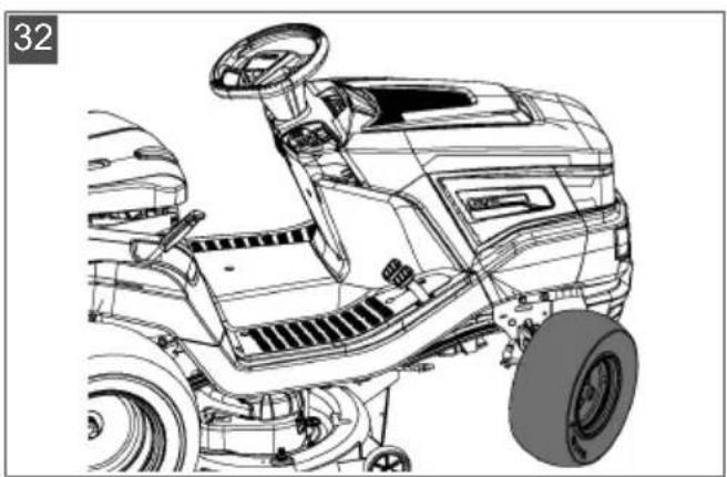
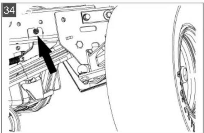
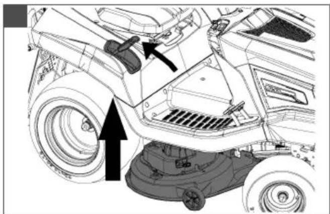
9.5 Removing the mower mechanism
The mower mechanism must be removed in order for the tractor to be used for snow clearing and for renewing the V-belt.
- Turn the steering wheel to full left lock (32).
- Remove the grass catcher (33).
- Remove the discharge channel (18).
- Unscrew the cap screw (34) on the channel holder by 5 - 6 turns.
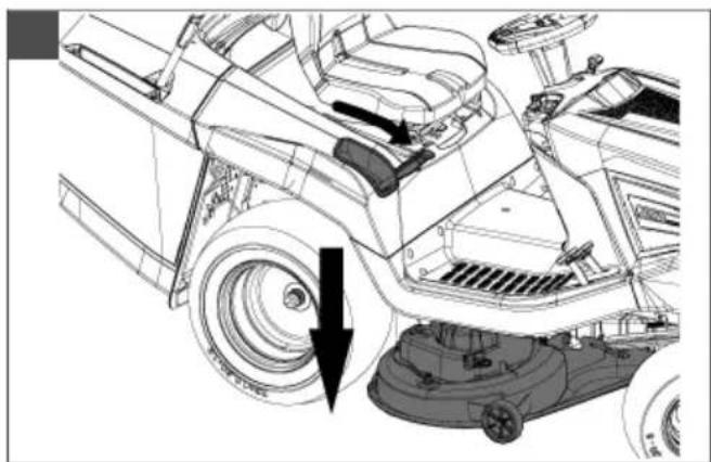
- Lower the mower mechanism to the lowest setting (35).
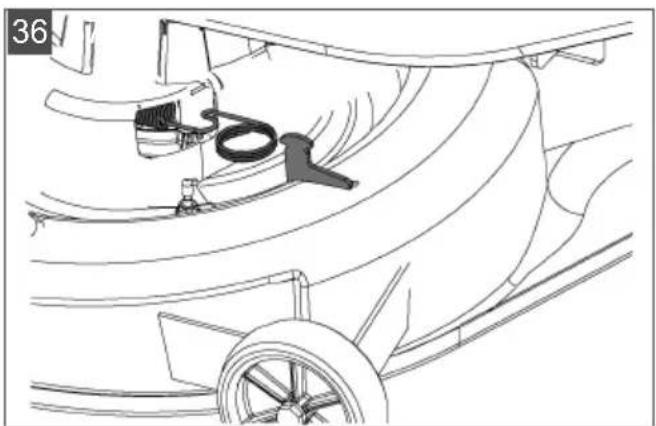
-
Unhook the tension spring on the mower mechanism (36).
-
Move the mower mechanism back up to the top (37).
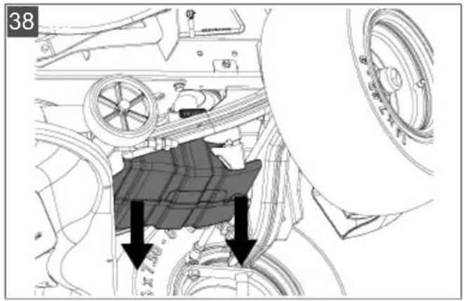
- Disconnect the V-belt duct (38).
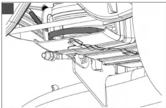
- Unhook the V-belt from the V-belt sheave of the engine (39).
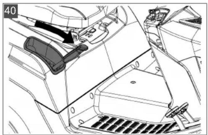
- Lower the mower mechanism back down to the lowest setting (40).
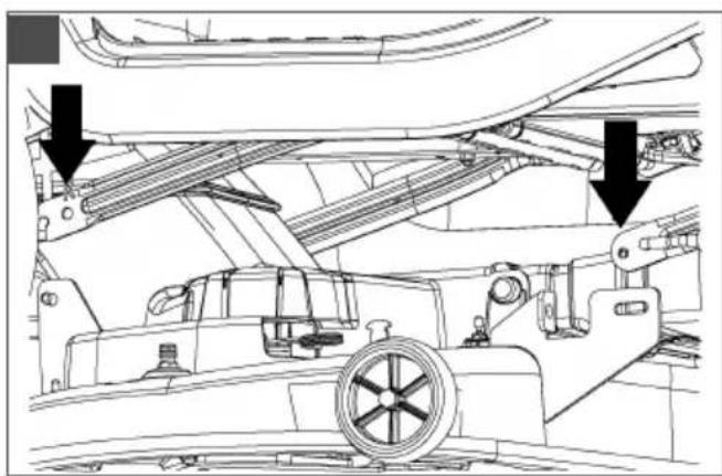
- Remove the 4 locking pins from the holding clips of the mower mechanism (41).
- Pull off the holding clips over the pins (41).
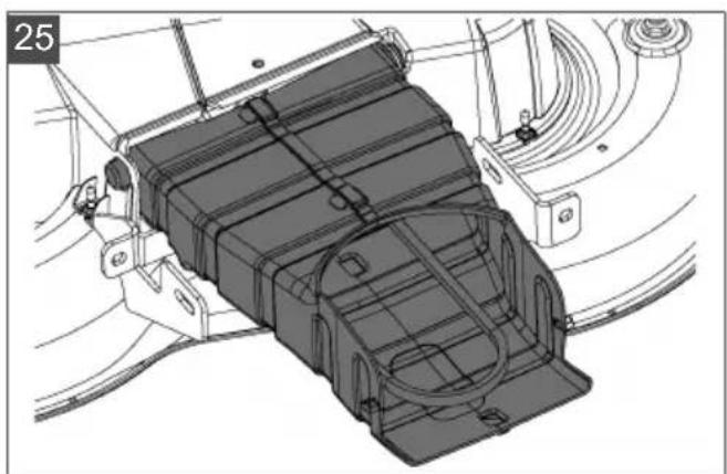
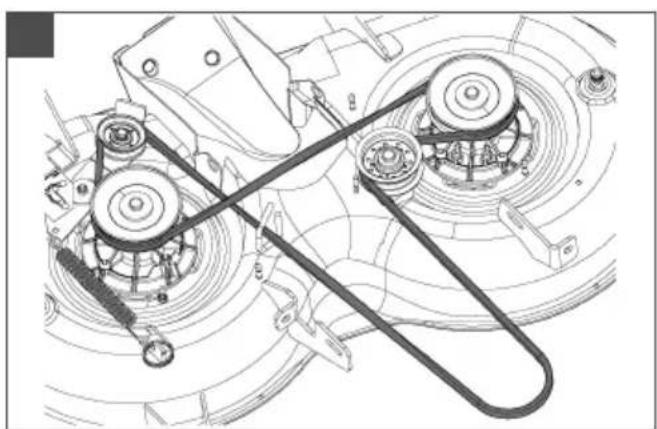
9.6 Renewing the V-belt
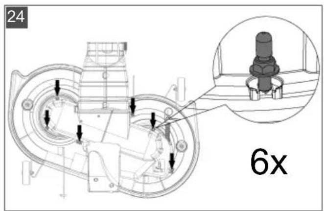
- Unscrew 6 locking nuts (24).
- Disconnect the V-belt duct (25).
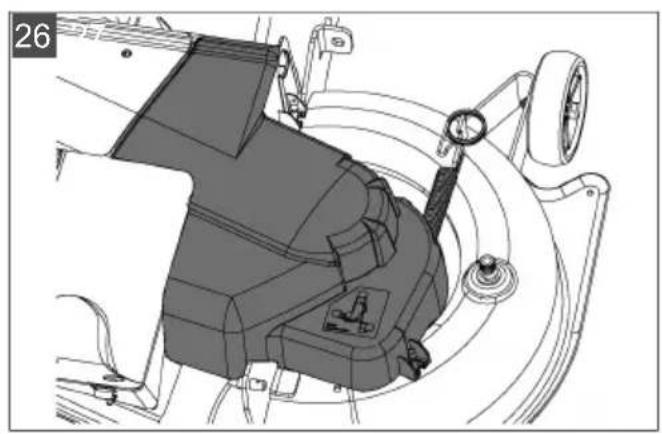
- Unhook and remove the right cover of the mower mechanism (26).
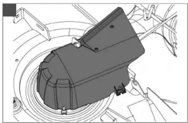
- Unhook and remove the left cover of the mower mechanism (27).
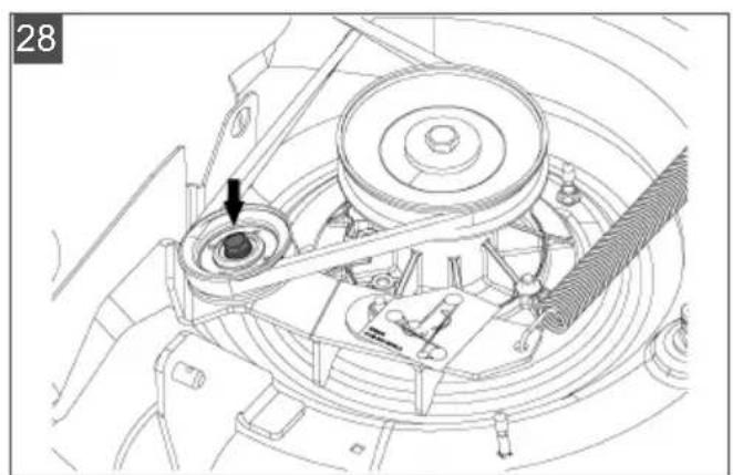
-
Unscrew the screw on the tensioning pulley slightly until the V-belt can be unthreaded (28).
-
Remove the V-belt.
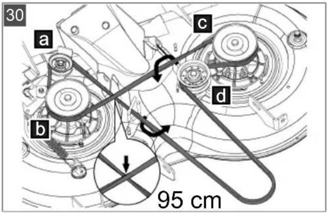
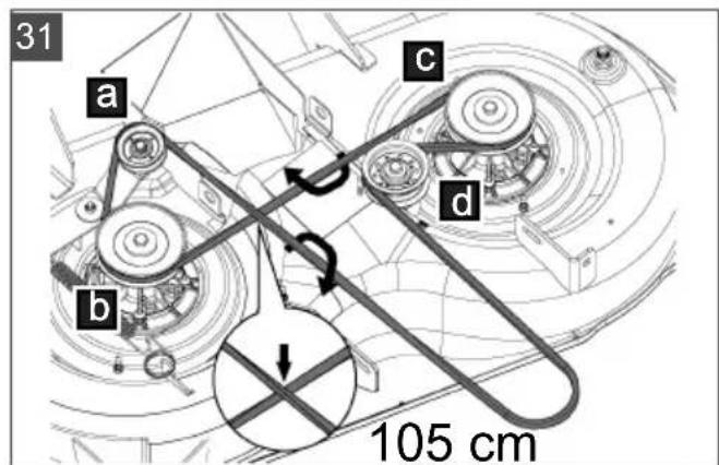
NOTE The guidance and orientation of the V-belt differs from type to type. Refer to the information stickers on the mower mechanism.
Inserting a new V-belt
- Place the V-belt around the slightly loosened tensioning pulley and screw the tensioning pulley on again (30 / 31).
- Place the V-belt around the rollers in the indicated sequence, making sure that the guidance and orientation of the V-belt are correct.
10 TRANSPORT
When the lawn tractor is transported using transport equipment (e.g. trailers towed by cars), the mower mechanism must be supported from below in order to reduce the strain on the mower mechanism mounting.
During transport, make sure that the means of transport has a sufficient load capacity and that the lawn tractor is suitably secured.
11 STORAGE
The lawn tractor should be parked where it is protected against the effects of weather, especially moisture, rain and lengthy exposure to direct sunlight.
Never store the lawn tractor inside a building when its fuel tank contains fuel, if there is potential for fuel vapours to come into contact with na
ked flames or sparks. Only park the lawn tractor in rooms that are suitable for the storage of motor vehicles.
When storing the lawn tractor for long periods, such as over winter, it should not have its fuel tank filled if possible. The fuel can evaporate.
Before long-term storage, the fuel should be drained from the tank and the carburettor in order to avoid any build-up of deposits, which could result in problems when starting. Please contact your specialist workshop for advice.
12 HELP IN CASE OF MALFUNCTION
CAUTION! Risk of injury. Sharp-edged and moving appliance parts can lead to injury.
Always wear protective gloves during maintenance, care and cleaning work.
NOTE For malfunctions that are not listed in this table or that you cannot resolve yourself, please contact our customer service.
| Malfunction Cause Remedy | ||
| Engine does not start. | Lack of fuel. Fill tank; check tank bleeding; check fuel filter. | |
| Poor quality, contaminated fuel, old fuel in tank. | Always use fresh fuel from clean containers; clean carburettor (customer service workshop). | |
| Air filter contaminated. Clean air filter (see operating instructions from engine manufacturer). | ||
| No ignition spark. Clean the spark | plug, replace with a new one if necessary, check ignition cable, check ignition system (customer service workshop). | |
| Too much fuel in engine combustion chamber due to repeated starting attempts. | Unscrew spark plug and dry off. | |
| Starter does not work. | Starter battery flat or weakly charged. | Charge starter battery. |
| Safety switch on operator's seat does not function. | Sit on operator's seat correctly; switch defective. | |
| Safety switch on brake pedal does not function. | Press brake pedal down fully. | |
| Mower mechanism switched on. Switch off mower mechanism. | ||
| Fuse on (+) cable of starter battery. | Check fuse, replace if necessary. | |
| Motor is losing power. | Grass too long or too wet. Correct the cutting height; make clearance for mower mechanism by moving back a short distance. | |
| Discharge channel/mower deck blocked. | Stop engine and take out ignition key! Clean discharge channel/mower deck. | |
| Air filter contaminated. Clean air filter (see operating instructions from engine manufacturer). | ||
| Carburettor setting incorrect. Have the setting checked (customer service workshop). | ||
| Blades severely worn down. Replace blades (customer service workshop). | ||
| Driving speed too fast. Reduce driving speed. | ||
| Lawn tractor is vibrat-ing severely. | Mower mechanism is damaged. Check mower mechanism (customer service workshop). | |
| Lawn tractor does not move off. | With hydrostat drive: no travel drive. | Move bypass lever to operating position (see chapter 7.3 "Pushing the lawn trac- tor (15, 16)", page 38). |
| Rough cut. Blade worn, | blunt. Renew or regrind blade. Reground blades must be rebalanced (customer service workshop)! | |
| Incorrect cutting height. Correct the cutting height. | ||
| Engine speed too slow. Set maximum engine speed. | ||
| Driving speed too fast. Reduce driving speed. | ||
| Different tyre pressure at wheels. Inflate to correct air pressure. Read off correct tyre pressure on tyre. | ||
| Grass catcher does not fill up. | Cutting height set too low. Correct the cutting height. | |
| Grass is wet – it is too heavy to be transported by air stream. | Mow at a later time when lawn has dried out. | |
| Blades severely worn down. Change blade. (Customer service work- shop) | ||
| Grass in lawn too tall. Mow grass twice:■ 1st pass: max. cutting height■ 2nd pass: desired cutting height. | ||
| Fabric bag blocked – no air throughput. | Clean fabric bag. | |
| Discharge channel/mower deck contaminated. | Clean discharge channel/mower deck. | |
| Fill level display does not respond. | Mown grass stuck to fill level dis- play lever. | Remove mown grass from fill level dis- play lever. Then check for ease of movement. |
| Travel drive, brake, clutch and mower mechanism. | Only have the check performed in a customer service workshop! | |
12.1 Fault and fault rectification error shown on display
| Display Fault Fault description Fault rectification | ||
| Err 01 Seat switch ECU detects invalid status of the seat switch. | 1. Switch the ignition off and back on again (position 2)**2. Apply load and release load from seat several timesSelf-diagnosis, if necessary, automatic deletion of the fault*, otherwise contact Service | |
| Err 02 Brake switch ECU detects invalid status of the brake switch. | 1. Switch the ignition off and back on again (position 2)**2. Press the brake pedal several timesSelf-diagnosis, if necessary, automatic deletion of the fault*, otherwise contact Service | |
| Err 03 Mower mechanism switch | ECU detects invalid status of the mower mechanism switch. | 1. Switch the ignition off and back on again (position 2)**2. Press the mower mechanism switch several timesSelf-diagnosis, if necessary, automatic deletion of the fault*, otherwise contact Service |
| Err 04 Box switch ECU detects invalid status of the box switch. | 1. Switch the ignition off and back on again (position 2)**2. Open and close the box several timesSelf-diagnosis, if necessary, automatic deletion of the fault*, otherwise contact Service | |
| Err 05 Transmission switch | ECU detects invalid status of the transmission switch. | 1. Switch the ignition off and back on again (position 2)**2. Press the reverse pedal several timesSelf-diagnosis, if necessary, automatic deletion of the fault*, otherwise contact Service |
| Err 06 Discharge channel contact switch | ECU detects invalid status of the discharge channel switch. | 1. Switch the ignition off and back on again (position 2)**2. Remove and re-install the discharge channelSelf-diagnosis, if necessary, automatic deletion of the fault*, otherwise contact Service |
| Display Fault Fault description Fault rectification | |||
| Err 07 Mower mecha-nism contact switch | ECU detects incorrect sta-tus of the mower mecha-nism output. | 1. Switch the ignition off and back on again (position 1)Self-diagnosis, if necessary, automatic deletion of the fault*, otherwise contact Service | |
| Err 08 Start relay ECU detects incorrect sta-tus of the start relay output. | 1. Switch the ignition off and back on again (position 1)Self-diagnosis, if necessary, automatic deletion of the fault*, otherwise contact Service | ||
| Err 09 Solenoid valve ECU detects incorrect sta-tus of the engine solenoid valve output. | 1. Switch the ignition off and back on again (position 1)Self-diagnosis, if necessary, automatic deletion of the fault*, otherwise contact Service | ||
| Err 10 Ignition coil ECU detects incorrect sta-tus of the ignition coil out-put. | 1. Switch the ignition off and back on again (position 1)Self-diagnosis, if necessary, automatic deletion of the fault*, otherwise contact Service | ||
| Err 11 Internal supply voltage | ECU detects incorrect sta-tus of the internal supply voltage output. | 1. Switch the ignition off and back on again (position 1)Self-diagnosis, if necessary, automatic deletion of the fault*, otherwise contact Service | |
| Err 12 Internal supply voltage monitor-ing | ECU detects incorrect sta-tus of the internal supply voltage monitoring. | 1. Switch the ignition off and back on again (position 1)Self-diagnosis, if necessary, automatic deletion of the fault*, otherwise contact Service | |
| *: * The display goes out for about 4 seconds.**: Delete the error by pressing the R key (03/13). | |||
13 GUARANTEE
We will resolve any material or manufacturing faults on the appliance during the legal warranty period for claims relating to faults, in accordance with our choice either to repair or replace. The legal warranty period is determined by the legislation of the country in which the appliance was purchased.
Our warranty promise applies only if:
The warranty becomes void in the case of:
These operating instructions are heeded
Unauthorised repair attempts
The appliance is handled correctly
Unauthorised technical modifications
Original spare parts have been used
Non-intended use
The guarantee excludes:
Paint damage that can be attributed to normal wear and tear
Wear parts that are marked with a frame xxxxxx (x) on the spare parts card
Internal combustion engines (these are covered by the guarantee provisions of the corresponding engine manufacturers)
The guarantee period commences with purchase by the first end user. The date on the proof of purchase is decisive. In the event of a guarantee claim, please take this guarantee declaration and the original proof of purchase, and contact your dealer or the nearest authorised customer service centre. This statement does not affect the purchaser's statutory claims for defects against the vendor.
VERTALING VAN DE ORIGINELE GEBRUIKERSHANDLEIDING
Inhoudsopgave
2 PRODUCTOMSCHRIJVING
Direction Description
9.4 Akumulatorski zaganjalnik
KoHTaKTHa 6paBa (02/4)
Pao
0 MoTOp nckIbvyeH.
MoKe ce n3ByhN KOHTaKTH N KJbYU.
I ApoBn cy yKbyeHn.
03/7 KOD n3BaHe He KyTne 3a CaKynJaHbe TpaBe Hn KaDa Hnje
PpONuCHO 3aTBopeHa.
03/8 KoJyKbByeHnxpeΦnkeKTopa.

03/9 kaJa je KoUHua aKTbBnpaHa n KoD 6NoKnpaHe KoUHnue.

03/10 ka ja je y pezeepboapy ocTano jow camo otnpnlnke 1,5 n ropnb.
03/11 KaJa HNBO yBa HJne DOCTnrao npeDbHJeH NBO.

03/12 KaJa Bo3aCnJeGa TpaKTopa JOK:
MOTOPpaNn (KoUHnca je 6nokupaHa)
5.3 Peda KaouHnue KBaunla (05)
KouHnca: Kaa neany 3a Kouehe (05/1)
CTNCHTe Do Kpaja, aKTINBnpa Ce KoUHnca npHeOCHnka N TpaKTop KOuN.
I Napknnpa KoHnca: AKO KOd CTnchyTe neJaIe KoHnce (05/1) nobUyeTe pyuCy 3a 6Jokady (05/2) npema rope, KoHnca he ce 6JoknpatN. HOBIM CTnCKaHbem neJaIe KoHnce OTnyuTa ce KoHnca.
5.4PykoBaHbe npeHocnKOM (6p3nHa BOxHbe) (04)
BpTHn TpaKTopn cy onpeMbeHn HOxHM XndpoCTaTckIM npeHOCHNKOM.
HekmOeN cy onpeMbeHn Temnomatom.
KoBoxHe npema Hnpei Ha3aHa DecHOJ cTpaHc Ce Hana3e DBe nOce6He neJaIe.
Cmep
BOXHe
Onnc
Hanpei Ctsncnte dechny peany (04/2) 3a BOXHy npema Hanpei.
Ha3aCtncnTe neBy nepany (04/1) 3a BOxHb y npema Ha3a.
HaNoMeHa:Ako ce CTnUcHe cAmO neJaIa 3a BoKbY npema Ha3aI, KocnIIuca he ce NckbYuHTN.
Ioroh 3a KoUHbY KOd BoXHe npemaHa3aD: BnN IooJa6Be 7.5.5
"Kowebe epmHum mpaKmopom", cmpaHa 183.
5.5 HoxhnxnpocTaTcN npehochnK (04, 05)
Hoxn xnpocTaTcN npenocnK ce ykbuyje y3 nomoh dBe neaJe (04/1 n 04/2).
KoI nokpeTaHa TOKOM paJa MOTopa npBO OTnycTe napKnnpHy KoUHnUy (05/2) n 3aTm CTnCHnte neany (04/2) 3a BoXbY npema Hanpei nnneany (04/1) 3a BoXbY npema Ha3aJ. WTo BnWe CTnCHeTe neany, To heTe 6pxe Bo3nTu y Oda6paHOM cMepy.
Boxha npema Hanpei: CTnCHnte Ha dechoj cTpaHn cnoJbHy neany (04/2).
Boxha npema Ha3a: CTnCHnte Ha dechoj cTpaHn yHyTpauhBy neaJy (04/1).
YKbUyNBaHe/NUCKJbUyNBaHbTe TEMNOMATA:
3akpeHnte puuuy (02/3) npema rope. Temnomam ce yKJbuyje.
3akpeHnte pyuNy (02/3) npema done. Temnomam ce uckjbyyje.
7.5.4 BoXbα n KoWeHbe Ha naDnHaMa
YNO3OPEHbE! OnachocT KoI rpewaka TOKOM BOXbHe Ha NaINHaMa! KoI BOXbHe Ha NaINHaMa 3axTeBa ce noce6Ha Do3a onpe3a! HnjeHa NaINHa Hnje ,6e36eHa". Y Tom clyuajy ce yBek npndpxabajte cnehehnx 6e36eHocnHex HanomeHa! Ako ToKOBn npoknky nIn ce
BO3nIO KOJ peHbHa y36pdo 3ayctaBn, OJBOjnte KocnIuCy n npKbByKe. 3aTm ce cnopom BOxHbOM yHa3aD oPxAbaJyH paBaH cMep CnyCTnte Hn3 naHy! NyH KoW 3a cacynBaHe TpaBe CBojOM TeXINHom NObeHaba onachOCT OJ PpeBpTaHa BpTHor TpaKTopa!
HemojTe Bo3nHa NaIHHa Harn6a npeKo 10^ (18%).Пример:To odroBapa BucnHcKoj pa3nOu 18 mNo DyKHOM MeTpY.
HemojTe BO3HTn ca HaJIIM KpeTbAma.
Hemoite Hargno kOHTN.
OdpkaBajTe Hncky 6p3nHy BoXHe.
Hikada HeMoTe BO3nTn nonpeuHo npema naHH.
HemojTe Hargy6p3aBAtn.
H36erabajteHarJe note3e ynpaBbaayem.
7.5.5 KoWeHBe BpTHHM TpaKTopom
Ja 6nCTe noCTnI npueu3aH pe3yIITa KooHe, 6p3nHy BOXHe Tpe6a npnaTOIu TYcNObMa Ha TpaBbaky. KoKoUeHa neJaIOM 3aJaTe MaKcImaJIHO 2/3 Moryhe 6p3nHe BOxHe. MakcImaIIHa 6p3nHa TpaKTopa NCKbByuHBo je IpeDbHJeha 3a nOrOH BOXHe 6e3 yKbByeHe KOcINlne.
Y HopmaHOM cnuyajy BnCnHa pe3a je 4-5 m. To odroBapa 2. nnn 3. HnBOy peryIaTopa BnCnHe (06/2).KoB BlaxHe m Mokpe TpaBe Kocnte BNIM IOdeWeHem pe3a.
KoB BPNO BnCOKe TpaBe npenOpuybNo je KocNTu y Dba uNKnyCa. KoI npBor uNKnyCa NOdecTe KocNnUy Ha MaKcMmaJHy BucnHy pe3a. 3aTm KOd dpyor uNKnyCa MoKeTe NOdecNTu XeJIbeHy BnCnHy.
7.5.5.1 YKbbyuBaHbe KocnIuCe
HANOMEHA Kocniluca ce cme yKbbyuHTeK Kaia je MOTOP paNIO np6nXHo jeaH MInHyT y TOnIOM cTaHy! KoD yKbuyBaHaKocniluce BPTHn TpaKTOp ce He CME HAna3NTu y BVCOKOJ TpaBN.
1.Покренте мотор.
2.Пребацпerte pERYnatop (02/2) 6poja obртaja MOTopa y paDNHy no3uNiy.
3. POnecnte KocnHcy Ha MaKcMaJHy BucnHy pe3a (06/2).
4. YkbyuTe KocnHny npereN6Hm npekndaem (02/5, noIoxaj 1"
5. Puyuom (06/2) nopeceTe JbeHy BnCnHy pe3a.
6.ПпимakнITE ce BpTHM TpaKTopOM.
7.5.5.2 Noroh 3a KoUb y KoD BoXHe npema Ha3aD
HANOMEHA Ako CTnCHnTe cAmo neaIy npehocnka 3a BoXb y PpeMa Ha3ad, KocnIua he ce nckbuyntn.
- CTnCHnte Tactep 3a "KoUb y npema Ha3aD" (02/6) n y poky od 5 cekyHnI cTnCHnte nepaIy (04/1) 3a BOxHy npema Ha3aD.
YNO3OPEHbE! OnachocT od Hecpehe KOD KOUHe npema Ha3a! PpaTe cTpaxhN OKoJIHn IpocToP npuIKOM KOUHe npema Ha3a! KocTe npema Ha3aI camo KaJa je To notpe6Ho!
7.5.5.3 NckIbIyUHbIe KocnIuIe
YIPO3OPEHbE!OnachocT Ko3aycTaBbBa HoxeBa!PotnpajyHn/In3na3eHn HOKMOKeNoceHnyPkyHore!DpxNtepyke HOREdaBeODMexaHn3ama3aceHe!
1.ИckbyuHTe KocnJInu npere6Hn mpeknDaem (02/5, noLoXaj ,O").
KocnJIuca ce MoKe NCKbByuHTN TOKOM MnpoBaHa n BoXHbe TpaKTopa.
YNO3OPEHbE! OnachocT od nobpeDe O6aueHn npeMeTnMa! KoI npelaKeBa IOBpUnHa ca UJbYKOM N OOpem MOrCy Ce NOByh npeMeTu y NOKpeHyTu KocuNtuN u N36aun.
Nckbvynte Kocnuiy yBek KaJa npela3nte NOBpHInHe Koje Hcy TpaBHate.
7.5.5.4 Пражье He kyTиje 3a cacynlaHbe TpaBe
HANOMEHA KaJa ce KyTuJa 3a cakynbAbe TpaBe HanyH, yJe ce 3ByuHn cnHaI. HajkachNe caTpe6a nCnpa3HHTu KyTuJy.
3aBncho Od BapnjaHTe onpeMe, BaW BpTHN TpaKTop je onpeMbeH eNEkTpHuHM npaxhBeHem KyTne 3a ckyIbaHe TpaBe IIN KyTJom Ha pyuHO aKTbHpaHe 3a ckyIbaHe TpaBe ca aKTNbauHOm pyuHcM.
3a cBe KytJe 3a cakynbAbe TpaBe BaXn Cnepehe:
Ppaxhbe Kytje 3a cakynbahe TpaBe MOKe ce N3BecTN ca cDenuTa BO3aHa.
Ako ce KOD aKTbBpaHe KOcHnue OTKnONn ININ OTKaUN KyTna 3a cAkynBaHbe TpaBe, MOTOp he pectaTn da paN.
Ako kytnja 3a cakynbahe TpaBe Hnje npabnHO yINaBbeHa, Kocnua ce Hehe MoHn yKbByuNTn.
PpaxHbeHe eNeKTpnuHe kyTnje 3a cakynbahe TpaBe
- 3a npaxhbehe ynoTpe6nTe npere6nnpekndau (07/1) Ha neBoj cTpaHn ceiWtbaO3aHa.
- 3a 3aTbapaHe kyTnje 3a cakynbaHbe TpaBe nHOBO yNtpe6nte perei6Hn npeknaq.
PpaxKheHe kyTne 3a cakyNbbaHe TpaBe aKTnBaCNoHOM pyuNcOm
- 3aTnM n3ByuNTe aKTNbauNHO npny u3 Kytnje 3a cakynbahe TpaBe (17/a).
- CTnCHnTe pyuNy y cmepy BoXhBe da 6n ce OTBOpnJa KyTna 3a cakynbAhe TpaBe (17/ 6).
- Померптуктуни за саллбаяе Травец ручим пема над дok ce He углави Ктуни.
7.5.5.5 MaJynpaJIbe
3a onTImaHaH pe3yIITaMaJnHpAba Tpe6a peoBHO KocHTu TpaBy (OTnpNnke 1 do 2 nyTa ceMnHo).Y TOM cIyajy OndeXKeTe 1/3 BnCnHe TpaBe (Hnp. TpaBy BnCnHe 6 cM nokocTe 2 cM). TaKo ce NOKoSeHa Tpaba Jako MoKe KopNCtHTn ca npoeCTaON TpaBOM.
7.5.5.6 INTepBaI KoiHbe
Y3MnTe y 063np To Da Tpaba y pa3nHTo Do6a pacte pa3nHtOM 6p3nHOM. IpeOpuyje ce Ha noyEtky npoleha Oda6paTn KpaHn INTEpBaI KOshBe. IObehajTe INTEpBaN KoUhbe aKO 6p3Ha pacta Tpabe NOUHe ONaDATN TOKOM rOdInHe.
Ako ce TpaBa HeKO BpeMe Hnje MOrJa KocNTu, npBO Oda6epnte NDoEseHbe BnSe BnCInHe pe3a n 3aTm HAKOH DBA DaHa NHOBO KOCHTe NoDeUeHOM HNXOM BnCINHom pe3a.
7.5.5.7 Kowene Bncoke TpaBe
Kocnte nopeheBem Bwne BucnHe pe3a ako je TpaBa Hapacna npeKO cTaNapdHe BucnHe nIkaJa je npebnaXHa. 3atm NOHOBO KOCnte TpaBy HIXM, HopMaHIM nopeheBem.
7.5.5.8 OdpkaBaHe HOKeBa
Tokom uele ce30He KOWeHb na NobpHInTe ce da cy HoxeBn OoTprn Da 6n Ce n36erIIO OTKnDaIbe nn dpo6Jbe cTa6bNka TpaBe.OTknHyTe cTa6bNke TpaBe Ha py6obMa noctajy CmeJe. To cMaHByje pact n nobehaba ocetJBnBOcT TpaBe Ha pa3He 6OJectn.
IpoBepnte HOKeBe HaKOH CBAKOr pe3aHaN 3Haka nCTPOWeHocTn nn OwTeHeHa! N0 Notpe6n NocETnte cepBnCHy paNoHy.
KoI 3aMeHe HOKeBa KOpNCTnTe cAmO opuHaJIHe pe3epBHe HOKeBe.
8 YIWIHTHeBEBPTHOTPAKTOPA
3a onTImaHHy fynKcunjy n Dyro TpaJaHe BpTHn TpaKTOp Mopa ce peoBHO uNCTNTN.
HaKoH cBaKOr paJa oUHCTnTe npJbAUBTInHy HAcynJIbeHy Ha BpTHOM TpaKTopy.
3a Ynshhe He HemojTe KopncntTu nepaay BucOKOr npNTska. Mna3 BoJe nepaay BucOKor npNTska nnBpTHor UpeBa MoKe Da oWTeTu eJekTpKu nn JexkajeBe.
Ia3nte Ha To Da Noce6Ho MOTop, npeHocnK INCKpeTHN BaIbU, KAO N KOMnIeTHa eJeKTpNka HeDohy y KOHTaKT ca BODom.
UIO3OPEHbE! OnaCHOCTN KOD
UHHeBa! KoI cbnx paOba uHHeBa BaKIn cnehe:
Ickbvynte MOTOp n 3ByuNTe KOHTaKTTH Kby.
I3ByuNTe yTuKaU(e) cBeHua.
3aHTnTHeIeMeHTu yKIOHeH npe uHHeBa Mopajy IHOBO 6HTu MOHTnpaHn HAKOH uHHeBa.
ONACHOCT OJ ONEKJIHHE: BpTHn TpaKTOp YIcTInTe TEK HAKOH ITo 6ynde pacxnaJeh.MOTOp, npeHOCh MExaHn3am n npriyuWbau 6yke cy BeOMa Bpyh!
ONACHOCT OJ IOCEKJIINHE: KoJ paOba Ha aIaTIma 3a ceYebe Na3nTe Ha OwTpE HoxKeBe. KoJ aIaTa 3a KoUeHe ca BnSe OuTPnca KpeTbA aIaTa 3a ceYebe MoKe Da n3a3ObE KpeTaHBe dpyrOr aIaTa 3a ceYeHe!
8.1 Ynshhebe kyTne 3a cakynbahe TpaBe
Pn Tom CkHnTe KyTuJy 3a CaKynJaHe TpaBe n nonpckajTe je N3HyTpaN CnoJa CpeBOM 3a BODy. TbpDokOpHy npBaBHTnHy Mopa ce onpe3Ho cactpyraTn,Ha npimep YeTKom.KoK cyTne 3a caKynBaHe TpaBe ca NnAtheHOM o6NoROM Noce6HO Na3nTe Ha To Da Ce He OwTeN PnATHO.
HANOMEHA Ipe uuheHa nCnpa3HnTe KyTjy 3a cakynbaBe TpaBe Ha ONUcaHn HauH. Nyha Kytja 3a cakynbaBe TpaBe je cyBnWe Teuka Da 6n Ce MoRna 6e36eHNo CKNHyTu.
Bahebe kytnje 3a cakynbahe TpaBe
1.ИckьучиTe MToTOp.
- IaraHO noDnHnTe kyTuJy 3a cakynbahe TpaBe.
- KyTnju 3a cakynbahe TpaBe n3BaJnte npema rope.
Bahebe eeneKtpnHe kyTne 3a cakynbaHe TpaBe
1.ИСКБУЧИТЕ MOTOP.
2.Пбинite ce da eileKtpnHa KyTuJa 3a CaKynBaHc TpaBe 6yde 3aTBopeHa.
3. LaRaHo noDnHnTe kyTnju 3a cakynbAbe TpaBe (otnp. 30^
4. Kytnjuy 3a cakynbbahe TpaBe n3BaAnTe npema rope.
8.2 Ynshhebe kyhnuTa, MoTopa n npehoCHnka
IAXHbA! OwTeheBa eNeKtpnHnx Hnctanaunja npoDnpyHom BODom! KoI uShHeBa TpaKTopa BODom Na3Nte Da BODa He npoDpe yHytap eNeKtpnHnx nHcTanaunja!
Motop n CBe JexkajeBe (KoTaue, npehocnK, Jexkaj HOxa) HEmoJTe PpCKaTN BOOM Hn Nepaem BNCOKOr pntncka.
Boa koja npoepe yHyTap ypehaja 3a naBeHe, Kap6ypatopa nФntep Ba3dyxa MoKe Da n3a3OBe KBapOBe. Boa yHyTap leXajeba MoKe Da n3a3OBe r6nTak Ma3nBa n yHnTbaHe neXajeba.
3a yknaBaBe npJbawHTnHe n octataKa TpaBe KOpNCNTe Kpny, Metnuy, KnCT ca Dyrom IDPJKOM NIN CnHNO.
8.3 Ynshhebe kaHajla 3a n36aunBaHe (18)
PeOBHO uHHe he rapaHTyje npomeHy BucnHe pe3a 6e3 nKaBnx npo6nema.
KaHAn 3a n36aunBaIbe ce cactojn Od DBA MehycobNo yByueHa DeLa. DoBn Deo je YBpctO yrnaBbEn y KyHnTe CKnona 3a KoUhBy. TOpHn Deo MoKe Ce n3ByHn KOn YnUHeHa.
- YknHnTe Kytjy 3a ckyjBaHe TpaBe.
- YknOHTe BnJke (18/1) JeBO n DeCHO Ha KaHany 3a n36aunBaHe (18/2).
3.ИЗВуцптЕ канДаиЗБацИВанБе КрОЗ 3aДиН 3ИД ПЕмА Na3aД. -
TemeJbnto OuchTe TropHn I DOHn KaHaI 3a n36aunBaHe.
-
YtaKHTe KaHJI 3a N36aUNBaHe y yTuHNuY. PtN TOM Na3NTe Ha To Da ce rOpHbN I DOBbN DeO MOV NaKO CaCTaBtN.
- 3aTeHnTe ra ca o6a npuBpcha Bnka.
- Mohtnpajte kytnjy 3a cakynbahe TpaBe.
9 ODPKABAHBe
YNO3OPEHbE! OnacHocT KoD
cepBncupaHa! KoI CBnx paOba cepBncupaBa Baxn cnehe:
Ickbvynte MOTOp IN N3ByuNTe KOHTaKTHN KJbvy.
I3ByuNTe yTuKaU(e) CBeHua.
3aHTTNHeJemeHTN yKIOHeH npe cepBncupaHa Mopajy NHOBO 6HTn MOHTnpaHn HAKOH cepBncupaHa.
ONACHOCT OJ ONEKJIHHE: BpTHIM TpaKTopom paAnTe TEK HAKOH wTo 6yde oxnaheH. MoTOp, npeHOChM mExaHn3am IN npnryuBau 6yke cy Beoma Bpyh!
ONACHOCT OJ IOCEKJIINHE: KoJ paIoba Ha aIaTIma 3a ceYebe na3nte Ha oUtpe HoxeBe. KoJ aIaTa 3a KOSeHb e ca BnWe OuTPnca KpETb aIaTa 3a ceYebe MoKe da N3a3OBe KpETb y DpyrOr aIaTa 3a ceYebe.
KoI 3aMeHe DeNoBa DOnyUTeHo je KOpNCTHTn cAmO OpRnHaJIHe pe3epBHe DeIOBE.
Ycnyajy IBOj6e yBek 3aTpaxnTe nomoh ctpyuhe paIIOHe mII KOHTaKtnpajte npOn3Bohaya.
9.1Планоджаваьа
Cneedehe paOBe cMe da n3BOu caM KOpNCnK. CBe octaIe paOBe odPxaBaHa, cepBncpaHa an nonpaKe Mopa Da n3BOu OBnaShHeHa cepBncha paAnOHua.
HANOMEHA Pn jaKOM ONTepeheHy n BVCOKIM Tempepatypama Mory 6ntu Notpe6Hn KpaHn INTePbAIn OdpXkaba Hero y rope HabeJeHoJ TabeJI.
Takohe cneinte npenopyeHa, roiHb a
noMa3nBaHa y cknaDy ca nHaOM
noMa3nBaHa.
9.6 3aMeHa KJInHAcTOr KaHsa
- OTnyctnte 6 6e36eHochnx Habptkn (24).
2.Obecnte KaHaJI KInHaCTor KaIsha (25). - OTKaHTe IdecHn NOKJOnaU KocNJInCe n yKIOHNTe ra (26).
- OtkaunTe JEBN NOKnonau KocnInuCe N yknOnHte ra (27).
- Mano otnyctte Bujak cTe3aça TaKo da ce KInHaCTn KaIIM MoKe I3ByhN (28).
6.ИЗвадиTe KINHaCTи KaIIш.
HANOMEHA Bohuna n noloxaj
KINHaTcTg KaIsha pa3NkkyjCe 3aBnCHO Od TIna.
YBaXnTe HaJIeHnHcy ca yNyTcTBOM Ha KocnHnU.
PpimHeHa HOBOr KInHaCToR KaHsA
1.ПОLOXHTE KINHACTN KANU OKOMANO OTNYHTEHOR CTe3HOr BaJbKa N NOHOBO 3aTERHNTe CTe3HN BaJbK (30/31).
2.ПОJOXHTe KINHactn KaIbOBIM peDOM OKO BaJbKa I npaTte BOHnUy I NOJoxaj KINHactor KaIsha.
10 TPAHCNOPT
KoT TpaHcnpTa BpTHOR TpaKTopa TpaHCnOpTHIM ypehajima (Hnp. npNKoJIuOm 3a INuHO BO3NIO), Mopa ce NODMeTHyTN KocNIuCa 3a pactepehebe OBeueHa KocNIuCe.
KoTpaHcnpTa na3nTe Ha DOBOJbHy HOCNBOCT TpaHCnOpTHor CpeDCTBa I npNKJaIHO yBpuhHe BpTHor TpaKTopa.
11CKJIaIuIwTeHbE
BpTHn TpaKTop Tpe6a DpxKaTu Ha MeCTy 3aUHTHHeHOM OJ HENOBOJBHX BPEMeHCKNX ycNoBa, NOCe6HO BnaRe I dYrOr INPeKTHOr n3IraHa bcauHcBoj paNuajnJ.
BpTHN TpaKTop HnKaJa He CkJaAdnTnTe ca
rOpNBOM y pe3epBoApy yHyTap objekTa, y KOM
MOxe DoHn Do KOHTaKta napa TropNBa N PnAmHa
Hn BapNuca. BpTHN TpaKTop DpxKeTc camo y
IpoCTOpNJama npNKJaADnMa 3a dpXaHe
MToPbNX Bo3nla.
I36erabajTe cKnaDnWHTTN BPTN TpaKTOp ca nyHm pe3epBoaop rompuBa Ha duXe BpeMe, Hnp. TOKOM 3nme. TOpINBO MOKe nCnapNTn.
Ipe dnyroptajhor cknadnshheha tpe6a
ncnyctntn ropnBO n3 pe3epboapa n
kapbypatopa da 6n ce cnpeuHIO taIooxebe n
36or tora npo6nemnpnnkOM nokpeTaBa.3a
nomoh ce o6patnte cneunjann3ObaHOJ paNHOH.
12 NOMOY CNYAJY CMETHBn
ONPE3! Onacnoct od nobpe. Owtpn INOKpeTHN DeIOBn ypehaja Mory da DOBey Do NOBpeDa.
Ppunikom paIOBa OndpKaBaHa, Here n uHHeBa yBek HocHTe 3aHTnThe pykabuie!
HANOMEHA KoI cMeTHbI KOJE HnCy HaBeJeHe y OBOJ TaBEn NII KOJE He MoKeTe Da OTKnOHNTE cam, ce o6paTInTe NaJoCnyK6n 3a KOpNCnKe.
IapaHunja He o6yXbata:
OwTeHeHaJaKa Koja ce CBoe Ha HopMaHHO TpoWeHe
IOTPOUHe DeNoBE KoJn cy Ha KapTnCi pe3epBnX DeNoBa 03HaueHn paMOM XXXXX (x)
Motope ca yHytpaHbIM caropeBaHbEM (OBte BaKe noce6He rapaHThe oDpeIbe npou3BoHa a MOTopa)
Iapantn pok noHbe da Teue od daTyma KynOBHe oC tpahe npBor kpaJbEr Kopncnka. Mepoaaban je daTym ha paUHy. Ca OBom n3jabOM o rapaunjN i opuHaJIHM paUHom obpaTnte ce npoabuy nHn Hajobnkoj obnaushenoj cepBnchOj padnoHnCi. OBom n3jabOM ce He Mehajy 3akOHcKa npaba Koja Kynau hMa npema npoabuy y cnuyajy HeDocTaTaka.
TŁUMACZENIE ORYGINALNEJ INSTRUKCJI OBSŁUGI
Spistresci
S hydrostaticickou prevodovkou
Fremad Traed pa den hore pedal (04/2) for at kore fremad.
Bak Traed pa den venstre pedal (04/1) for at bakke.
Vip armen (02/3)ned.
Tempomat slas fra.
Koble inn klippeaggregatet
Uždegimo spynele (02/4)
Padetis Veikimas
0 Variklis ijsjungtas.
1.1 Cnmboln Ha NaaHaTa cTpaHua
CnmboJ 3haueHne

Henpemehno npoetete BHmataelno Ta3n INCTpykun 3a ekcnloatau npednyckane TO EKCnloatau. Toba e npednoctabkaT3a 6e3onacha pa6ota n 6e3npo6nHa pa6ota.

PbKOBOIDCTBO3aeknnoatauia
He pa6oTeTe c 6eH3nHOBna ypei 6n30 do OTkPNT PnAmbK nnn n3-TOUHN Ha TOnnHa.
1.2 Pa3aCHeHna ycNoBnTe 06o3HaueHnN n CnHaJIHnTe dymn
ONACHOCT! Obo3NaHauBa HEnocpeIcTBeHo OnaCha CHTyaCn, KOrTO - aKO He 6bJe N36ErHaTa - MoKe Da IMa KaTo NocJIeIcTBHe CMbPTIIN TeKko HapaHraBaHe.
PENyPExEHNcIaHaONaCHaCITyaUKoT0-AKOHe6bDeH36erHata-BmMOrNa DaDObeDo CMBpT NJI TeKko HapAHBaHe.
BHIMAHNE! O6o3NaHaBa nOteHcuaJIHo OnaHa CnTuaCnI, KOrTo - aKO He 6bJe N36eHa-Ta - MoKe Da IMa KaTo CneDCTBVe JeKO IJN UMepeHO HapaHraBaHe.
BHIMAHHE! Obo3haaba cnTyauaun, KOaTO -ako He ce n36eHHe - MoKe Da npedn3BnKa MaTeepnaHn 1eTn.
YKA3AHNE CneuHn yka3aHna 3a no- do6po pa3bnpaHe n bopabeHe.
2 OINCAHNE HA IPOJyKTA
TpaKTOpIte 3a KocHe Ha TpeBa cbc 3aAnHO n3-XbIpJIHe ca npOn3BeDeHn B pa3JIuHn MoJeN. 3a CneHNTE OncaHn B TOBa pKoBOdCTBO, MOJyBepTe ce, ye CTe npOyeN OncaHneTo, NOxOJaIO 3a BaIINr TpaKTOp 3a KocHe.
XapakTepeuCTnHa Baunr TpaKToP 3a KocHe:
IpeaBaTeHmexaHn3bM:KpaueHxndpocTAT
KynnyHHa HOXA: eJneKTpOMarHnTeH
Osem Ha KoHTeHepa: 310 I
I3npa3BaHe Ha KOHTeHepa: eJeKtpuYecko, TeJeckOnuyeH IOCT
OcBeH TOBa HMa pa3NIkN Ipn CnCTeMNTe 3a MyJIuHpAHe, TIIa MOTOp, MOUHOCTTa Ha MOTopa N IupHaTHa pr3aHe.
Pa3nIKB MoJeNITe:
山nHaHa p3aHe
Tnp npedaBateHa kytna (T3 n G700)
Bai nac Ha npedaBaTeHnMexaHn3bM- de6nokupaHe
2.1 N3noJ3BaHe no npedHa3NaueHne
TpaKTopbT 3a KocHe e npeHa3HaueH 3a KocHe Ha yacTHn I Domaun H rpaDInH c MaKc.10° (18%) NaKIOH. DOnbIHNTeHN npINOKeHna, KaTO Ha-NpIMep, MyNupaHce ce pa3peWaba camo npu N3-NOJ3BaHc Ha opRHaJIHNTe akCeCoApn i Cna3-
BaHe Ha MaKcImaJIHInTe CToHOCtN Ha HAtOBapBaHe.
To3n ypeE npedHa3HaueH cAmo 3a YacTHa ynoTpe6a. Bcya dpyra ynotpe6a kAKTO HEno3BOJeHN peKOHCTpyKUIN NIN BHACrHE Ha DOnbHInTeHH enemeHTn Ce CHTa 3a yNoTpe6a He nO npedHa3HaueHne, IN BOi KaTO NOcNeCTBne Do OTnadaHeTo Ha rapaHcNtA, KAKTO N 3aY6aTa Ha CbOTBeTCTBnEtO (0603HaueHneTO CE) IN OTka3a OT OTROBOPHOCT Ha pON3BOJNTeJI 3a UeTI, PnUnHeH Na Notpe6nteJI INI HA TpeTA CTpaHa.
2.2 Bb3MOxHa HnpaBnHa ynotpe6a
TpakTopbT 3a Kocene He e npedHa3Haueh 3a KoMepcnaHa ynoTpe6a B oBseCTBeHn napKOBe, CnpTHN CbopBXeHn, CeNCKO CTOnaHCTBO n RopCKO CTOnaHCTBO.
I PEPDyPPEKDEHNE! Onachocn ot npetoBapBaHe Ha TpaKTopa! Korato n3noJ3BaTe pemapke, yBepTe ce no-CneuHaNo, ye He npBnShaBaTe DOnyCTUmnte HaTOBapBaHnHaKaIOHN Ha ONbH. IpeBnShaBaHeTo Ha TOBa MoKe da DOBeDe Do BLOshaBeHa cNpuHaTa eΦeKTHBHOCT Ha TpaKTopa n Da DOBeDe Do ONaCHn CHTya-
YKA3AHNE MoJra, oBbPheTe BHMaHne, Ye TpaKTopbT 3a KocHe Ha TpeBa He e yJIuYe H He MoKe Da Ce N3NoJ3Ba No O6IeCTBeHN PtTu-
2.3 CnMBoJn no ypeJa

Ipei nyckaHeTo B eKcnnoataa n npoTeTe pkoBOdCTBOTO 3a ynoTpe6a!
IIO Bpeme Ha KocHe DpyrN Jn-ua,OCObeHO Deu a N KINBOTHn, Tp6Ba Da ce DbpxkT daJeu OT pa60THOTo MRCTO.
I3BaTe KOHTaKTHN KIOU nppe nn pOdpbXka n peMOHT!
BHHMaHHe onaChoc! Pa3eTe pb- ceTe n KpaKaTa daJeu ot pexe- uia HOx!
He wOΦnpaTne no cKnIOHOBe c Na1 10^ (18%) HaKJIoH!

Onachoct: He xoJeTe Tyk!
Onachoct ot n3raphe ot ropese NOBbpxHoctn!
2.4 3aunTHn n npedna3Hn ycTPOcnCTBa
PNEyPExEHNcOnctOT npemaxHaTn mHmynnpaHn npedna3Hn npncnoc6lenh! Bcka pa6ota c npemaxHaTn nMaHnynpaHn npedna3Hn npncnoc6lenh e 3a6paHeHa. DepeKTHnte npedna3Hn npncnoc6lenh Tpr6Ba da 6bde pemOHnpaHn nIcMeHen He3a6abHO!
PpeNa3HnTe npncno6JeHnB KJIIOuBaT nocneuaJHo:
CnnpaueH KOHTaKTeH npeKcbau
KoHTaKeH npeKbcBaH Ha KocayHmexaHn-3bM
KoHTaKTHe NpeKBcBaU Ha KOHTeHepa 3a Cb-6npaHe Ha TpeBa
KoHTaKTHe npeKbCBAu Ha cdaJkata
Kanaun Ha kocaykata
KoHTaKeH npeKbcBaH ha KaHana 3a n3XBbpJIaHe
2.5 IperneHa npoynka (01)
KoHTaKTeh KJIIOU (02/4)
CnnpaHnT KOHTaKTeH npeBKnIOyBaTeI rapaHTnpa, Ye DnIraTeJIr He MoKe Da 6bJe CTapTNpaH, aKO CnpaKaTa He e 3aDeiCTBaHa.
1.ДВИРATEЛЯТЕи3KЛЮЧЕN
2. CeHHeTe Ha ceaJkata Ha Bodaqa.
3. OcbobodeTe pBuHaTa cnnpaKa, KaTo HaTnCHeTe neJaHa cnnpaKaTa (05/1).
4. OnntaTe Da cTaptnape Te Bnrgate Jn (KoHTAKTHNAT KIOUe B NOJoxKeHne III).
YKA3AHNE DBratelT He Tp6Ba da ce cTapTnpa!
6.6.2ПоверkaHaKoHTaKTHnI npekbcBaHаКocayHmexaHn3bM
KoHTaKTTHnT npeKbCBAu Ha KocaykaTa rapaHTnpa, Ye DnIraTeJIr Hma Da CTapTnpa, KOraTO KocauHnT MExaHn3bM e aKtNbUpaH.
1.ДВИТЕЛЯТЕиЗКЛЮЧЕН.
2. CeHHeTe Ha ceaJkata Ha BodaJa.
3. HatncheTe cnnpaunnneJa05/1) n 3a- npbXte pbHaTa cnnpaKa (05/2).
4. BkIIOUeTe KocauHn MexaHn3bM (02/5, N0-3u1n“1").
5. OnntaTe Da cTApTpate Dniratela (KoHTAKTHNAT KIOUe B NOJoxKeHne III).
YKA3AHNE DnuratJeT He Tp6Ba da ce cTaptnpa!
6.6.3 Поберka Ha KOHTaKTHnЯ npeKbCBaHа ceJaNKaTa
KoHTaKTnHrT npeKbCBAu rapaHTnpa,Ye DnurTaTeJrT Ce n3KnIOUyBa,BedHara cIeN KaTO npBknOueH KocayEH MExaHN3bM Beye Hma YOBek Ha ceDaJIkaTa Ha BODaYa.
- CēnheTe Ha cêdaɪkKaTa Ha BɔdəuA.
- HatncheTe cnnpaunnne (05/1) n 3a- dpbxte pbuHaTa cnnpaKa (05/2).
- CstaptnpaIte DnurTaTeJn Iro octaBeTe da pa60Tu c MaKcImMaJIHn O6OpOTn.
-
BkIIOUeTe KocauHn MexaHn3bM (02/5, Noo 3uIN "1").
-
Ocbo6oTe ceaankata, kato ctaheTe (He cn3aTe!).
YKA3AHNE DnIraTeJIaT TpI6Ba Da ce n3-KJIOUH!
6.6.4 Поберka Ha KOHTaKTHnI npeKbCBAuHa KOHTeHepa 3a c6bnpaHe Ha TpeBa
KoHTaKTTHnT npeKbCBAu Ha KOHTeHepa 3a Cb-6bpAne Ha TpeBa yCTaHOBRA, Ye DBrAteIaT Ce n3KnUOyBa, IOM KaTO KOHTeHepbT 3a Cb6pAne Ha TpeBa pN BKNIOueH Kocayeh MExAHn3bM He e 3aKaueH npabnlo.
- CeHHeTe Ha ceaJkaTa Ha BOdaYa.
- HatncheTe cnpuaHnna (05/1) n 3a- dpbXte pbHaTa cnpuaKa (05/2).
- CstapnpaIte DburaTeJn Iro octaBeTe da pa6oTn c MaKcImaJIHn O6OpOTn.
- BkIIOUeTe KocauHn MexaHn3bM (02/5, N0- 3Ncui“1").
- Повдигнеле Лко паЗня Контейнер 3a CB-6иране на Трева Или Натиchede п配电ьсва-уа 3a OTВарян.
YKA3AHNE DnraTeIa Tp6Ba da ce n3-KIOUH!
6.6.5ПpoBepkaHaKoHTaKTHnI npeKbCBAu Ha KaHaja 3a NxBbPnHe
KoHTaKTTHnT npeKbCBAu Ha KaHana 3a n3XBbpJIHe yCTaHOBRA, Ye TpaKTOpbT 3a KocHe He MOKe Da Ce BKNIOU npi DeMOHTnpaH KaHaI 3a n3XBbpJIHe.
- Cbaene KOHTeHepa 3a cb6npaHe Ha TpeBa.
- OTrpaheTe KaHana 3a n3xBbPnIHe (18/2).
- CeHHeTe Ha ceJaIkata Ha BODaHa.
-
HatncheTe cnpuHnna neJaI (05/1) n 3a- dpbkTe pbHaTa cnpuKa (05/2).
-
CtraptupaTe motopa.
YKA3AHNE DnBraTeJrT He Tp6Ba da ce cTapTnpa!
7 PA6OTA C TPAKTOPA
PNEUYNPEXDEHNE!Onachoctn nopa- Hn HeoctaTbUHO No3HaBaHe Ha TpaKtopa! PpoTeTe BnMaTeJHo IHCTpyKuInTe 3a ekCnnoataun, npEn Da 3anOHTe pa6To! O6bpHeTe CneuaJHo BnMaHHe Na BCNUHnHCTpyKu nn 3a 6e3onacHcT! BnMaTeJHo n3blnHaBai
Te BCNUKMOHTaXHn pa6OTn N BCNUK pa6OTn NO BBBeJdaHe B eKcPiOaTaUa. AKO mATE cBmHeHn, nonTaNTE npON3BOuNTeI.
7.1 OCHOBNI NOIROTBUNH MEPKN
IIO BpeMe Ha KOceHeTo BnHaRn HocTe 3dpaBn ObyBn N DbJIr NaHTaNoH. Hnkora He Kocete BoCn nJn C OTBopeHcHdaJI.
I IpoBepTe N3qJNo TepeHa, Bbpxy KoTo ue ce N3POn3Ba TpaKTopa 3a KocHe. OTCpAHe-Te BCnUKN KaMbHn, npbUKN, TeNoBe, KOkAnu IN DpyrN CyXKn TeJa, KOnto 6nxA MoRn da 6bDaT XbaHaTu IN 3xVBpNeHn HAcTpaHn. Cb-IO n IO BpeMe Ha KocHe Tpr6Ba Da ce BnMaba 3a CyXKn TeJa.
N3BbpeTe BCnUKN pa6OTn, ONnCAHN B nH-CTpykuaTAta 3a NyckaHe B ekCnloataaun. ToBa BaXn CneuHaHO 3a npOBepKaTa Ha npedNa3HNTe npncnoc6JeHH.
3a TerIeHe Ha TOBapn N3NoI3BaIte cMoTerIuHa! He npEbnuaBaIte BepTnKaIIHnA TOBap.
TpaHcnpTpupaHTo Ha npEmdEtHa TpaKTopa He e no3BOJeHo!
7.2 N3noJ3BaHe Ha akcecoapn
I PDEUYPEXJEHNE! OnachocT OT He npabunnakcecoapu nHn HnnpaBnHO 3- noJ3BaHe Ha akcecoapu! N3noJ3BaIte camo opnHaJIHn Akcecoapu OT npOJ3BOJnteJHa TpaKTopa! Cna3BaIte npabunata 3a yNoTpe6a B npINOxKeHTE NHCTpyKcUN 3a EKcnIooatauia!
I3noJI3BaHTo Ha HeoO6peHn akceCoap nIHNepaBnHa yNoTpe6a Ha akceCoap mOKe da npEiN3BnKa roJMa onaCHOCT 3a OnepaTopa IN TpeTn Nua. TpaKToPbT MoKe Da 6bJe npTeTOBapeH. ToBa MoKe Da DoBeDe Do TeKKn 3IonoNyKN.
7.3 Bytahe Ha TpaKTopa 3a KocHe (15, 16)
BHIMAHHE! Onacnoct npn 6yTahe no ckNoHOBe! BytaIe TpaKTopa cAmo Bbpxy Xopn3OHTaHNI NOBbpxHocTn! Bbpyc KcNoHOBe TpaK-TOpt MoKe Da ce 3aADBIXn HeKOHTpOJInpyeMo HaDony.
Pn 3aBnKBaHe c KpaueH XndpoctaT
BaiNaChnT NoCT (15/1) ce HAmnpa Ha 3aHaTa KOlecha Hnla.
Дeблokиране на 6aynaca npn T3-ckopoctha kTuTna (Tun: T15, T16, T18):
1.ИЗдьрайт eбайпасня loct (15/1)и ro onbHeTe Harope (16).
2. Ocbo6oTe cnpaaykata.
Cera TpaKTopbT 3a KoCeHe MoKe Da 6bJe npemecTeH.
Yka3aHn 3a 6e3oNaCHOCT
PENyPExEHNc!OnachocT ONHe npaBnHO 6opabeHe cbc cTapTePHna aKymIaTOp!3a da n36erHete onachocTH,KoTo Mo- rata Bb3NkHaT pRn He npaBnHO 6opabeHe c akymIaTopa,cna3BaIte cneHIne yka3aHnI
CTapTePNrT akymyIaTOP He Tp86Ba Da ce CbXpaHbBA B HenocpeDCTBeHa 6n3OCT Do OTKPIT ObH, Da CE n3rapn NIOCTABB Bbp-xy HArpeBaTeJI. IMa OnaCHOCT OT EKcNIO-3nJ.
CbxaHЯBaIe CTapTepHnaAkyMaIaTop npes3 3mata B xHaNo n cyxo NomeuHne (10-15°C).No BpeMe Ha cbxaHene Tp6Ba Da ce n36yRbat TemnepaTyPi ND HyaTa.
He octaBnTe cTapTeHnAkyMylatop He-3apeDen 3a npoIbJnxIteH nepNoD OT BpeMe. Ako cTapTeHnA kMyIaTOp He e 6nI n3no3BaH 3a npoIbJnxIteH nepNoD OT BpeMe, ToI Tp8Ba Da ce 3apeXda C noDxo- Draio 3apAnHO yCTPOINCTBO.
He nobpejdaIte cTapTePNHa aKymyIaTOP. EneKtpoNtBt (cApaHa KnceJIiHa) npuynHbA n3rapHnHa KaXkata N O6NeKJIoTO - He3a- 6abHO n3MnIte 06nIHc BOJa.
IopdbpkaTe cTapTepnna akymyNatOp
ynt. N36bpcBaiTe camo cbc cyxa Kbpna.
He n3no3BaTe BOda, 6eH3nH, pa3peiTeJ
nIu npyn noo6h!
IpbkTe Cbbp3BaunTe NOJIOCN UcTn n mCMAKeTe C NOJIIOHa rpec.
He cBbP3BaIe KbcO cBbP3BaIuTe noJIIOcN.
3apekdahe Ha cTapTePnHa kymyntop
3apeKdaheTo e 3aBnKInTeHNO:
Ipei cxbxpanHe 3a nouBka npe3 3nma-ta.
Pnno-npoDbJnxTeJeH npctoHa ycTpoiCTBOTo (NoBee oT 3 Meceua).
I PDEyPPExJDEHNE! OnachocT OT He npabnIHO 3apeKdaHe Ha cTapTeprHna Akymy- IaTOp! 3apAHHrT TOK Ha 3apAHHOTO yCTPOINCTBO He Tp6Ba Da HaDnBnUba 5 aMnepa, a Ha- npeXeHneTo Ha 3apeXdAne Tp6Ba Da 6bJe MaKc.14,4 BoNTa. Pnno-BuCoko HApexEne Ha 3apeXdAne CbIecTBvBa pNCK OT EKCnNo3n Ha cTapTeprHna AkymyIaTOp! BnHarn n3BaXdaiTe KOHTaKTTHN KJIou npn pa6ota c AkymyIaTopa.
IpenOpbUBaMe 3apeKdaHeTo Ha To3n CTapTepeH akyMynaTOp, KOHTo He ce Huxkdae OT NOddpBxKa I e yCTOuHB Ha ra3 Cbc CneuHaHO npedHa3HaueHo 3apAHO yCTpOiCTBO (DOCTbNHOOT CneuaHn3npaHn DnIbpr).
Cna3BaIte HNCTpyKUInTe 3a ekCnIIOaTaunHa npOn3BOIDNTeJI Ha 3apAHHOTO yCTpoINCTBO, npeDn Da 3apeINTE CTAPTEPHN AkyMynatop.
BHUMAHNE! OnachocOT KbcO cbeHHeHne! 3a da n36eHete KbcO cbeHHeHne, npbBO n3KnHcTe MNHycOBn Ka6e(-) ot akymyataTopa n ro Cbpxete OTHOBo! BnHaN n3BaxJaTKe KOHTAkhN KInOu npn pa60Ta c akymyNatopa!
1.Изва对接е Контактуг Клич (02/4).
2. OTbopete Kanaka Ha DnBraTeJ.
3. CbpxKeTe KneMnTe Ha 3apAHOTo yCTpOInCTBO KbM npCbeDnHInTe HnTe KneMn Ha akymyNaTopa.
YKA3AHNE CnasaBaiTe noJapHOCTTa:
YepBeHa KEma = noJoxKTeJeH nOJIoc (+)
UepHa KneMa = OtpuCaTeIeH noJIoc (-)
- CbpxKeTe 3apdHTo ycTpoiCTBO KbM MpeKaTa I rO BKIOUeTe.
9.5ДeMoHTnPaHe Ha KocaKaTa
3a H3noJI3BaHe Ha TpaKTopa npn 3mHn ycNoBn I 3a NOmHa Ha KInHOBn peMbK, KOcaKaTa Tp6Ba Da ce DeMOHTnpa.
- 3aBbPTeTe BolaHa HaJIaBO DoKpaI (32).
- OToCTpaHeTe KOHTeHepa 3a cb6npaHe Ha TpeBa (33).
3.ДемонтураiteKaHаla3aи3XBbprЯнe(18)
4. Pa3xna6eTe cHnHnpuHnBnHT (34) Ha dbpxkaHa Ha waxTaTa 5-6 o6opota.
5. CnycheTe KocauKaTa Ha NaHnckaTa Ha-ctpoiKa (35).
6. OTKaYeTe onbBaUcaTa npyKInHa OT KocayKaTa (36).
7.ПпемecTeTe KocauKaTа HaropeДokpaN (37).
8. Pa3kaye KaHana Ha TpaneOuHnpeMbK (38).
9. OTKaueTe TpaneucOBnHnpeMbK OTpeMbHaTa 7aB6a Ha DnRaTeJr (39).
10. CnycheTe KocaykaTa OTHOBo Ha Hau-NHcKaTa NaCTpoiKa (40).
11. CbaIeTe 4-Te OcHpyrntEnH uNΦTa HaCKo6nTe Ha Kocaykata (41).
12.Дрьн electcokobataуpe360JToBeTe(41).
9.6 CmHa Ha KInHOBnHnpeMbK
- Pa3BnIte 6-Te noDCnIpynteJIHn raIKn (24).
- Pa3kaye KaHana Ha TpaneOuHnpeMbK (25).
- Pa3kayeTe n OTCpaHeTe DecnKaNaK Ha KocauHm MexaHn3bM (26).
- Pa3kayeTe n OTCpaHete Jebn Kaan KaocauHn MexaHn3bM (27).
- Леко пахларе винта на объгаша ролka, ДOKATO КИНовдн我不是 ремьк може за сеизваши (28).
6.ИЗваде Te KINHOBNHЯ ремьК.
YKA3AHNE BoJeHeTo n NonoJKeHneTo Ha KInHOBnHnpeMbK ca pa3JIuHn B 3aBnCmOCT OT MoEJa. O6bpHeTe BnHMaHne Ha yKa3aTeHNHTe CTnKeepn BbPxy KocauHn MexaHn3bM.
NoctabrHe Ha HOB KInHOBnDeH peMbK
1.ПocTaBeTe KInHOBnHnpeMbK OkOJNo Jeko pa3xJa6eHaTa 06TgRa7a poJIka n OTHOBO 3a-BuIte 06TgRa7aTa poJIka (30/31).
2. NocTaBeTe KInHOBUnHnpeMbK CbIaCHO nOcNeIOBaTeINHOCTTa OKONO POJIKeTne I Cna3- BaIte BOeHTo I NO3uYraTa Ha KInHOBUnHnpeMbK.
10 TPAHCNOPTIPAHE
Ipn TpaHcnpOpTupaHe Ha TpaKTopa 3a Kocene C TpaHCnOpTHO O6OpUdBaHe (HaNP. ABTomo6nHn peMapKeTa), KocauKaTa Tpr6Ba Da 6bJe NODIbPkaHa 3a OCBO6OxJaBaHe Ha OKaUBaHeTo Ha KocauKaTa.
Pn TpaHcnpTnpaHcNpypeTe DoCTbUHa TOBapOHOCIMOCT Ha TpaHCnOpTHnte CpeDCTBa N NOxODAIO OBe3ONacBAHe Ha TpaKTopa.
11CKJIaIINPAHE
TpaKTOpbT 3a KOceHe Tp86Ba Da 6bDe 3aUHTeH OT aTMocOpeHN BnnaHn, Oc0eHo OT Bnara, DbXd N npOdbJnxTeHa nprKa CnbHueBa CBETnHa.
Hnkora He cxbxpaHbAaTe TpaKTopa 3a KocceHe C roPBO B pe3epBoapa B crpada, KbDeTo napnte Ha rOpNBOTOMoT Da Bn3aT B KOHTC OTKpNT orh nn nckpn. NapkpauTe TpaKtopa 3a KocHe caMo Ha Mecta, NOxOJaun 3a napKnpaHe Ha MOTOPHNpeB03Hn CpeDCTba.
3a no-DbIrrn nepnoiHa cBxpaHeHne, KaTo Hapnpimep cbxpaHHeN B 3IMHN yCIOBn, He napKpauTe TpaKTopa C nbJeH pe3epBoap 3a rOpNoBO. TOpNBoto MoKe Da ce n3napu.
Ipei npoDbJnxHcBxpaHHeHne, rOpBOTO Tp86Ba Da ce n3ToOn OT pe3epBoaapa N Kap6bypa
Topa, 3a Da ce n36erHaT OTnaraHn I NO To3n HauHn Da Ce 3aTpUdHn NysKaHeTO B EKcPiOaTaZu. Mon, nonTaIte Baunr CneuaN3npan cepBn3 3a TOBa.
12 NOMOUI PNI HEN3INPABHOCTN
BHUMAHNE! OnachocT OT HapaHbAHe. OcIpopb6ecTu n DBHXeUc Ce YacTn Ha ypeDa MORaT Da DOBeDaT Do HapaHbAHNu.
BnHaH npaBoTn no NoadpBXkKaTa, 6CnyXBaHeTo n NouchBaHeTo HocTe 3aunTH npKabu!
YKA3AHNE Ipn Heu3npaBHOCTN, KOUTO He ca nocoehn B Ta3n Ta6nua NIN KOINTo He MOxTe Da OTcpaHHTe CAMOCTOReTJIHO,MOJr O6bpHeTe Ce KbM Haata KOMnTeHTHa KIneHT- cKa cnjK6a.
| Heni3npaBnocT Пичина OtrctpaHЯВанe | ||
| Диагтелг He пал. Лпса Ha roрв. HanbIhete pe3epe Boapa; П探测ete Венилачида Na pe3eBoapа; П探测ete Горьни Фильtp. | ||
| Ен acquебено, замberсedoTo ro-pinbo,старо ratpoBв Be3eepBO-a pa. | ||
| Замberсен Bv3dUnSeH Фильtp. Рочидete Bv3dUnHЯ Фильtp (Вж.Инструкцinte 3a ekspnoatacna Na pro-n3BoDInteNa Na Dvinatela). | ||
| Ная мскра. Почидete ЗanalnteJHLHata cBeu, sme-HeTe, akO e Neobxodmo,探测ete Ka6eJa Na 3analBaHeto,探测eteСИCTemata 3a 3analBaHne (CepBn3 3aOBcIyKBaHne Na KIneHTn). | ||
| Поради МногokparTHи OniHTn 3aЗanalbaHe ИмТВьрдe MNoTo ratpoBв GopINbHaTa Kamepa Na DBiratela. | ||
| Стартуг He pa60-TN. | Прastsen ппс Stapterpenakymylatop. | |
| Пробетяпт ровкючbatel Na сedajkaTа Na Bodaua He pa-6otn. | ||
| Пробетяпт ровкючbatel Na спирочnyпедду He pa6otn. | ||
| КосачkaТа e ВknIOUeHa. ИЗklJOUeTe кoscakata. | ||
| Helen III ppabnocst Причuna ha OTcTpanhahe | ||
| Пре徳пазnteягт ha (+) кабела надстартугия akumулатор. | ПроберетеPre dedиаитelя, рпн Heob- ховимост ro smehete. | |
| Мошноctta ha DBVIGa- теля пада. | Тьрд e ВICOKа ил Тьрд Влжна Трва. | Кориграіte ВИСОЧИТа ha рязан; Налраве място 3a КOCAVKа та с leko Врьшане habад. |
| Канал 3a ИЗВьрлaine/KOCaЧNo Крп lo 3a npuшeni. | Изклочete DBVIGaTeЯ ИИЗВадete кON- Таftня Kлоч! Почстete канал 3a ИЗВьрлaine/KO- сачноу Крп lo. | |
| Замьрсен Bьзduшen Фильър. Почстete Bьзduшinя Фильър (ВЖ. Инструкцinte 3a ekspлоатаця Ha pro- ИзвODиTeя Ha DBVIGaTeя). | ||
| PergunpaHTo Ha Kapbypatopa He e nprabuInno. | Проберете НастpoиКATA (сервиЗ). | |
| Ножьт e сilnilo ИЗнoscen. Смение HOJA (сервиЗ). | ||
| СkopocTTa Ha DBVIXeHne e TBbpr- Дe ВICOKa. | Редуцраіte skopocSTTа Ha DBVIXeHne. | |
| Тракторггт 3a Косе Вибрupa сilino. | Косачka t a epovpeDEHa. Пrobерете КOSTа (OTdelen 3a ob- слухване Ha KlneHTN). | |
| Тракторггт 3a Косе He ce 3aDBVIXBa. | При ХицportаТИчно 3aDBVIXBa- He: Ная 3aDBVIXBaHne Ha XOdo- ВataЧAst. | Проберете Байсяпяст в pa- ботно положенye (ВЖ олава 7.3 "Бу- maнe Ha mpakmopa 3a KOCeHne (15, 16), cmpaHua 420). |
| HepabnO косе. Hoxьт e ИЗнoscen, He e HaTOUeH. CmEHete HOJA ил ГИоТe. Ba- Iahncipate NaTOUeHite HOXOBe (OTdelen 3a obScnyKbaHne Ha KlneHTN)! | ||
| Нэрпавида ВИСОИна Ha ряза- He. | Кориграіte ВИСОИнatura Ha KOSeHne. | |
| Тьрд e ИССа чecTota Ha Bbpr- TeHe Ha DBVIRATEA. | ЗадаітЕ МAKSCIMALnaЧecTOTA Ha Bbpr- TeHe Ha DBVIRATEA. | |
| СkopocTTa Ha DBVIXeHne e TBbpr- Дe ВICOKa. | HamaJete skopocTla Ha DBVIXeHne. | |
| Различно наляганe B ГIMTe Ha KOLJIaTа. | Hanommaіte Do nprabuINHOTO BbZdUnHNO наляганe. OtrchETe nprabuINHOTO NaIy- raHne Ha ГIMTe. | |
| Кontейнерггт 3a CB- биране Ha TpeBa He ce ПьлNi. | ВИСОИнATA Ha рязАе e Ha- СтрoeHa TBbprde Дылбoko. | Кориграіte ВИСОИнatura Ha KOCeHne. |
| Трава e ВЯЖнa - TBbprde TEXKa e, 3a Дa Бдe ТраHCSnop- ТираHa OT BьЗdUnHry Notok. | Олножete В��емeto 3a KOCeHne, ДOKаТо повьрхнocTТа 3a KOCeHne ИЗСБxHne. | |
| Hoxьт e сilnilho ИЗнoscen. Погмение HOJA. (OTdelen 3a obScljx- Ванe Ha KlneHTN) | ||
| Heni3npaBnOcT Пичина OTcTpaHЯВaHe | ||
| Тьрдe ВИСOKO пОДРЯЗВaHe Na TpeBaTa. | Косе He Na TpeBaTa Ha 2 nbTn: 1. П pemинаванe: мakc. ВИСочинa Ha ряЗанe 2. П pemинаванe: Леланa ВИСочинa Ha ряЗанe. | |
| Плathенят чУВал e 3aNYшeн - HЯма пИТOK Ha Bb3dUx. | Почистe Плathенячвал. | |
| Каналыт 3a ИЗХБрлЯнe КOCaH-HOTO крпLO са 3aMbрсeн. | Почистe Кэналa 3a ИЗХБрлЯнe/Ko-caЧНOT Oун. | |
| Индikatopьт 3a пьЛ- He He pearIPA. | Остыц nOТ КОсeнe Ha loCTa Na ИндikatOPa 3a пьЛHe. | Остранe OotaTBцte OT KОсeнe Na loCTa Na ИндikatOPa 3a пьЛHe. СпeД TOВa, поверeTe ЛeКОпДВиЖ-HocTTa. |
| ЗадиЖВанe Ha XODo-BaTaЧaT, спирачka,СъедиNTeI N Koca-Чeн MexaHиЗbM. | Проверкite Дa ce ИЗВБршВaT сamO ot OTdeJa 3a obcspuXВaHe Ha KПeHTn! | |
BHHMAHNE! Yka3bIbaeT Ha cnTyaunIO, KOTo-pa, ecn ee He n36eKaTb, MoKeT npNBecTu KnMyueCTBeHHOMy yep6y.
H PnmeyAHNE CneuaJIbHbIe yka3aHnA nIy oBJeHn IOnHMaHn I KcNpyaTaun.
2 OINCAHNE IPOdykTA
a30HbIe TpaKTOpbIC 3aDHeN pa3rpy3KoN n3roTabnBaOTcB B pa3nUHbIX KOHCTpyKunx. Y6eDNTecb B TOM, YTO Bbl B 3TOM pyKOBoIDCTBE NO EKcnNyatauNN Bbl YHTaeTe ONiCaHne, COOTBeTCTByUoUee BaWemy ra3oHHoN TpaKTopy.
XapaKTepnCTnKn ra3oHHO TpaKTopa:
Kopo6ka nepea: HOxHoi rInpocTaT
MydTa pe3ca: 3JIeKTPomarHHTha
Osbem emkoctn:310n
OnopoxHeHne EMKocTn: 3JIeKtpnueckoe, Te- neCKoNnueckn pbiur
Kpome TOrO, cyIeCTbYIOr TaKKe pa3JIuNpy B CnCTeMax MyJbUHPOBaHnry, TInne DBrIaTeTn, MOUHOCTn DBIrataTn n UINpuHe cpe3a.
Pa3nunmexkdy Tnarni:
山npuHa cpe3a
Tin kopobkn nepedaay (T3 u G700)
Pa36nKpOBKa oXoJa Kopo6Kn nepeaH
2.1 NcnoJb3ObaHne no Ha3HaueHnIO
Га30ньИ TраКТО npeДиЗаЧЕН ДЯ HeNPo-фecсиоHAЛьHOrO cKaшИВaHHЯ B YacTHbIX Domax npi KpyTN3He cKaTa MaKc. 10° (18%).ДононTeьhoe ИСпОЛьзOBaHHe, HApPIMeр MyЛьчИpoBaHne, pa3peSHAOTcЯ TOЛьКО C ИСпОЛьзOBaHHeM OригиHAЛьHbIX aKCECCyapOB I B COOTBETCTBnI C MaKcIMaHLbIMN 3HaueHINMaHarpу3KN.
3TO yCTPOIcTBO npEiHa3HaueHO nJy qacTHOIO NCNoIb3OBaHn. JIO6oe dpyroe IcNoIb3OBaHne IIN HeCaHKUOnHpOBaHHbIe N3MeHeHn I DO-NOJIHeHn CHTaOTcN cNoIb3OBaHnEM He IO Ha3HaueHnIO IN pINBOJrK aHHyInpOBaHnIO rapaHTn, a TaKKe Notepn COOTBeTCTBnR (3NaK CE) I OTka3 OT KaKoJ-JIn6o OTBeTCTBeHHOCt 3a Y-ueP6, HAnecHHbI NOpIb3OBaTeJIHO IIN TpeTbeI CTopoHe N3rTOBUTeJI.
2.2 Cnyan HnnpabnIbHoro npImeHnna
Га30НьИ TpaKTop HeпpeДиЗнayeн ДЯ KOMМерчecKOrO ИСПОЛБ3OBaHЯВ OБцEcTBeHHbIXnapkax,Ha CNoPTNIBHbIX ПLOДдКaX,B CeIbCKOMИ leCHOM XO3ЯICTbax.
PPEyIeHNE!Onacnocn n3-3a neperpy3knra3oHHoro TpaKtopa!BoBpem IcNoJIb3OBAHnI npuceNa CneIte 3a TeM, YTO6bl He ppeBbICHTb DOynCTHMble Harpy3ky N yKIOHbI/ nepenadbl. PpeBbIseHne MoKeT neperpy3ntb TOPMO3HyO CNCTemy ra3OHHO TpaKtopaN npINBeCTN K ONaChbIM cnTyaunm!
H NIPIMEYAHNE O6paTnte BHNMaHne, YTo ra30HHbI TpaKTop He pa3peWaeTcNcNoJIb3oBaTb Ha 6OeCTBeHHbIX Doporax!
2.3 CnMBOJIbHa yCTPOINCTBe
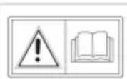
Ipeed 3kcnnyataaue npountaute nHCTpyKuH!
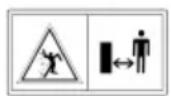
Bo BpemcKaunBaHnApyRne IIOi,OCo6eHHo DetnN XNBOT-HbI,DOJXHbI HaxOaNTbcraBdaJIOn OT pa6oey 30HbI.
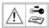
Ipepa6oTAMn noTexHnueckomy 06cnyKbAHnO n peMOHTy BbIHMaTe KIOU3axnraHnA!
BHMaHne! OnachocTb! BepenTe pyKn HOrn ot pexyUeRo MeXaHN3Ma!
He 3ae3kaIte Ha yKIOHbI BblIe 10^ (18 % )!

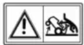

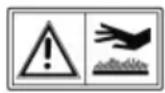
OnachocTb: He BXoNTb!
Onachoctb oKorOB n3-3a ropnyx nobepxhocte!
2.4 PpeOxpaHnteIbHbIe n 3aunTHbIe ycTpoiCTBa
PNEpyPExEHNc!OnacHocTB CBr-3nC ydaJIeHEm nIIMaHInyIpOBaHEm 3a- uHTbIMN yCTpOcTBAMn! IIO6aKcnPyatau npYdaJIeHmN nIIMaHInyIpOBaHm 3a- uHTbIMN yCTpOcTBAMn 3aIpeSeHa. HeicnpabHbIe 3aUHTbIe yCTpOcTBa Heo6xOdImo HemeJenHo OTpeMOHTpOBaTb nIIM 3aMeHITb!
3aunthbyeycTpoNCTBaBKnIOuHaOT:
IpepeknoateIb TopMo3HOro KOHTaKaTa
IpeeknouateIb KOHTaKTOB caIOBOrO TpaKtopa
IpeeknouateJIb KOHTaKTOB eMKoCTn dJa TpaBbl
IpeeknouateIb KOHTAOB cndeHbA
3aunTHbIe KpbIuKc aDobOTo TpaTopa
IpeeknouateJIb KOHTaKTOB pa3rpy3OuHOrKaHaJa
2.5 O63op npoDyKta (01)
Homep KomnoHeHa
1 PynéBoe koneco
2 NaHeJI npI6OpOB
3ПeДаЛТopmo3a
4 Kanot dBuraTeJra
5 PnBOD o6paTHoN nepeaun
6 PnBOD nepeDne nepeDaun
Homep KomnoHeHa
7KocnIbHbMexaHn3M
8 PerynipOBKa BbICOTb Cpe3a
9 O6xoJ kopo6kn nepea
10 DaTnK EMKoCTn DnTpaBbl
11 PnBOD EMKOCTN
12 EMKoCTb dIy TpaBbl
13 CnDHeBb BOIDTeJIa
14 Θлжкгческн ппвod emKocTN*
15 DepekaTeIb neaII TopMo3a
16 Pbyar kpyn3-koHTponr
- BapnaHTbI pa3JInuaIOTcI N 3aBnCrt OT KOHKpeT- HoN MoJeN
3 YKA3AHNIO TEXHnKE B3OpACHOCTN
3anpeuaeTcNcNoIb3OBAb yCTpoiCTBO DeTbMn ININ JInaAMn, He O3HaKOMNBUMMCnC DaHHoH IHCTpyKUnei.
Co6IIOaIte MeCTHbIe IpeIINcAHnO THO-CNTeJIbHO MInHMajlbHOrO Bo3pAcTa ONePaTopa yctpoiCTBa.
He pa3peaIe TeTЯM nNoIpoCTkAm IrgpaTb C yCTpOInCTBOM.
Pa6oTaTb MoXHO TOnbKO npn DHeBHom CBete nn npx XopoWeM OCEuEHN.
YdaIte NOCTOPOHNX NnC n3 ONaCHO 30Hbl.
OnepaTop nIN nONb3OBaTeJIb OTBeauHOT 3a KIn3Hb IN MyUeCTBO dpynx JnU.
Icnoj3ynte TOnbKO opnHaHbHbIe 3aacHbIe YactN I npHaJdJIeXHOCTN.
Pemont yctpoicTba DOJXeH BbINOJIHTbcn Ipon3BOiTeIeM HNI eRO cepBnCHoCnyx-60i.
IcnoIb3yIte cpeIcTba 3aIITbI opraHOB cnlyxa.
Ta30HHbI TpaKTop 3aIpeuaeTcNcNoJIb3OBaTb Ha o6eCTBeHHbIX doporax u yInuaX.
He BbINOHnIe cKaUHbAHne BO BpeM rpo3bl. CaObBm TpaKTop He OcHaueh 3aunToN OT MOHN.
3anpeaetcB03ntbHa yctpoiCTBe naccaknipoB.
He BbINOJIHnIe cKaUHbAHne Ha cKnOHaX Cyrnom 60Jee 10^ (18%)
3anpeaaetcpa6oTaB Cra0HHbIM TpaKToPOM N (nN) npKpeHneHHbIM K Hemy akcecCyapAMN B COCTOHN anKOroJbHO rnoHApKOTUeCKORO ONbAHENr IIN NOcNe npneMa nekapCTBeHHbIX npenapaTOB, BnnaIOxHa CKOpocTb peakun.
Bcerda BbinoJHnTe cKaunBaHne nonepeK oTKoca.
CobnOdaIte dInTeNbHocTb pa60Tb1,pa3pe-WeHHyHOHa MeCTe.
- Ra3OHHbI TpaKTOp MOKeT npNBecTu K cepBe3HbIM TpaBMam N3-3a Co6CTBeHHoro Beca. Co6JIHOJaTe ocTopoXHoCTb npn Norpy3-Ke n pa3rpy3Ke ra3OHOrO TpaKTOpa dJa nepeBo3KN B TpaHCnOpTHOM cpeDCTBe IIN npu-une.
3TOT ra30HbI TpaKTop He pa3pe7aETc8 6paTb Ha 6yKcnp. NcNoJIb3yIte NoIxOJaUeTe TpaHCnOpTHoe CpeDCTBQ DnI nepeBO3Kn NO MapuTyam O6ueCTBeHHOro TpaHCnOpTa.
He nCNoB3OBAbTa30HHbI TpaKTop B 3a-KpbItbIX NOMeueHnX INI NINOxo npOBETpN-BAembIX 3OHax (HaPnMep, B rapaxe). BbIXoONHbIe ra3bl coDEpkat JIOBHTbIy rApHbI ra3 I dpYrne BpeHNbIe BeuEcTba.
4 PACNAKOBKA N MOHTAX T3OHHO TPAKTOPA
Дя paçnaKOBи moTaxa ra3OHHOro TpaKTopa CM. npIraeMOe pyKOBOCTBO NO yCTAHOBKe.
I INPIMEYAHNE TaKKe co6JIIOdaTe npINJaRaEMoe pyKOBoIDCTBO IO 3KcIIyatauN 6eH3nHOBOrO DBrIaTeJ.
PNEyPExEHNHe!OnacHocTb n3-3a HenoHoh yctahOBKn!TaOHbI TpaKTop 3a- npeaaetcA KcNpyaTnpoBaTb DO NOHOb yCTaHOBKn! BblonHnTe BCE pa60tBIOYCTAHOBKe, O- nncAHhBie B pykoBODCTBe no yCTaHOBKe. B cny- yae comHneHn nepeB BBODOM B 3KcNpyaTaCIO Cnpocnte cneuaJINCtA,BblonHeHa IIN yCTaHOBka npabInbHo! Y6eINTecB H aHnUu N pa6OTcNO6HOCTN BCex ppeOxpaHnTeNbHbIX n 3a- uHTbIX ycTPOICTB!
5 3JIEMEHTbI UYPABJIENHIA
Hnke npBedeHbI 3JIeMeHTbI ynpaBHeHnra3OHbIX TpaKTopoB C 3aHHe pa3rpy3kOy. Y6eINTeCbB TOM, YTO Bbl YHTaTe OINcAHne, COOTBeTCTByIOUee BaWemy Ra3OHHomy TpaKtopy.
5.1 CtaHdapTha nHaJIb npI6OpOB (02)
JemeHbI cTahapTHoN nAHeN np6OpOB onNCaHbI Hxke.
UnpaBneHnue yacToToBpaSeHHaBnraTeJIa
I IPNMEUAHNE O6paTnTe BHHMaHne Ha
TO, UTO cpa6aTbIBaHne peryIaTopa B peXnMe DBNXeHnBnIeT Ha YactOTy BpaIeHn IDbIraTeIa!
PpumeyaHue. HeKoTOpbIe BapnaHTbl TpaKTopa OchauSeHbI OTdeJIbHOJ KHOJIKOI DPOCCEN (02/1) Ha naHeJI np6OpOB.
3aTeM ee Heo6xOIMHO HaxaTb dIy 3any-cka TpaKTopa. Ecnn DnBraTeJIb pa60TaET, MeIeHNO CHOBa HaxMNTe KHOKNy!

Pabota B pexime ckaunbaHnA: B 3TOM nIOXeHN I dBnIaTeIb pa6oTaET Ha MaKcMmaJIbHOJ YactOTE BpaueHnA.

PexmMaIoroXoJa:B3OMnIOJKeHn DnIraTeJIpa6OtaeHaMIMmaIbHOuacToTeBpaUeHn.
3amok 3axnraHna (02/4)
Yem CnIbHee Bbl HaxMeTe Ha neJaH, Tem 6blCTpee Bbl HaHuHeTe DBNrTaTbcra B Bbl6paHHom HaipabJIeHN.
Движенье BпepeД: HabKMITE Ha BHeUHIOI ne-danb (04/2) cnpaba.
Движени Ha3a:HaXmTe Ha BHyTpEHHIO neJaJIb (04/1) cnpaBa.
5.6 3Kcnpnyataa KocnIbHoro MexaHn3Ma (06)
PerynnpobKa BblcOtbl cpe3a
KocnIbHbMexaHn3M TpaKTopa MoXHO OTperyI npOBaT NO HeCKoJIbKIM yPoBnM BbICOTb C NOMOu bOp PbUcara (06/2) cnpaba OT cndeHbB BodInTeT.
- Nepemecnte perynnpoBOHbI pbuag (06/2) B HuxhOe HappaBJIeHne. OnyuEHHbI BHN3 pbUar 03Haayet MaMyIO BbICOTy cpe3a, NOJHrTbI BBepx pbUar 03HaayeT BoJbUyIO BblCOTy cpe3a.
BkJIIOHTe KOCINbHbIMexaHN3M
3JIeKtpnuecko coeHHeHne: B o6NaCTn naneHn np6bOpOB HaxoDntc nepeKlnuOaTeIb (02/5).
BkIOUHTe KocINbHbIM MexaHn3M (noIoxHe1)
6 BBOD B 3KcπIyATAUHO
PNEyPExEHNcHocb n3-3a HenoHou yctahOBKn!TaOHbI TpaKTop 3a- npeeaaTcA KcNpyAtnpoBaTb Do noHou yCTa
HOBKn! BbINOHNTE BCE pa6oTbI NO yCTaHOBKe, OnncAHhble B pyKOBOdCTBe No yCTaHOBKe. B cnyuae comHeHn nepeB BBOOM B 3KcNpyatauio CnpocHTe CneuaHnCTa, BbINOJIHeHa Ny yCTaHOBKa npabINbHo! Y6eINTecB H aHnUHn IN pa6OTcNO6HOCtN BCex npeDOxpaHNTeNbHbIX N 3a- uHTbIX ycTPOiCTB!
6.1 PpOBepka KocnIbHoro MexaHn3Ma
Ipepe nCnoJb3ObaHnem Bcerda npoBOuNTe BN3yaJIbHbIM OcMOTp pexyUero INCTpyMeHTa, KpeJnxHbIX 60lTOB IN BCERO HOKeBOrO 6JIOKa Ha npedmet n3HOca n NOBpeXdEHn. Bo n36eXaHne Dn6BaHaHCA n3HOSeHHbIe IIN NOBpeXdEHhble HOKn Heo6xOdIMO 3aMeHnTb HOBbIMN.
6.2 3aNoJHeHne Macnom
Ipeed nepBbIM BBOOM B 3KcNpyaTuHO dBnraTeIb Heo6xOIMO 3aNoJHHTb MaclOM. Ipr 3TOMcoJIIOdaIte pyKOBoDCTBO n3rOToBnTeIaDBnraTeIy. TaKke peryIpaH NOpOBepaIte yPoBeHbMacla DOJKeH 3aNoJHrye MaclOM.
6.3 3aNoJIHeHne ToIINBOM (09)
PNEpyPExEHNr!OnacHocTn npn
obpaueHn c TOnNtBOM!TOnNtBO 1erKoBocnnaMeHraUOuNCa MaepnA.3anONHrTe ToNNHBn6ak TOnbKO Ha OTKpbITOM BO3dyXe!3a- npeuaetc Kypntb!He 3ameHrToNtB, Korda DBnIatel pa60tae Hnn Harpenca!
ДяЗларвкTOПИВOMNcNoIb3yIte NOxOJa- 乌BOPOHkyIIN3aINBHyIO Tpy6y,YTO6blTO- IINBO He nonanoHa DBnraTeNb,KOpnyCIIN 3eMJIIO.
No coo6paqehnma 6e30nacnoctn B cnyuae noBpeKdEHH CneDyET 3aMeHHTb 3aTBOp TOnNHBHO 6aka n npn noBpeKdEHH.
Pn nepeJIbte TOnIIBa 3anpeucaetc 3anyckaTb DnIraTeIb. TpaKTop dONKeH 6bITb ydaIeH n3 30- Hbl, 3aRpy3HeHHo TOnIIBOM, a npOJItoE ToNIIBO Heo6xOIMOBnITaTb N BbITEpeTb TpIKNoC nona, DnIRaTeIg N Kopnyca.
I36eraTe IIO6bIX nonbITOK nycka Do ncnapeHn TOnnBbIX napOB.
XpaHnte TOJINBO TOnbKO B npEynCMOTpeHHbIX KOHTeHepax.
IcnoJb3yInTe HeaTnInpoBaHHbIeH3nH, MInH. ROZ 91.
3aNoJHHeHne 6aka
1.Пи Heo6xOIMOCn BbIKIOUHTe DBIgATEJIb NOTKIOUHTe KIOU 3aXINrAHHaNЯ dIЯ obecne-ueHna 6e3OnacHOCTn.
2.ДождnteCb oxlaJxdeHnДBuratena(onac-HocTb B3pbBa N3-3a Bo3ropaHnToTnnBa!).
3. HaxMMTe Ha KpbIuKy 6aka (09/1).
4. NobeprHTe KpbIshky 6aka (09/1) BBepx. KpbIshka 6aka pa36Joknpyetc (09/1).
5. OTKpOte KpbIky 6aka (09/2) n 3aONHnTe 6ak TOnJIbOM. IpuMeYae: N3beZaume nepenNoHHeHu monJueHo2o 6aka!
6. 3akpoTe KpbIkwky 6aka (09/2).
7. 3aKpOte KpbIkwky 6aka (09/1), yTo6bl 3aФNKcnpoBaTb ee.
6.4 PpOBepka DaBHeHnBa Bo3DyXa B uHHax
Perynpho npOBepaTe daBJeHna Bo3dyxa B uHHax.
IpoHTaTe Tpe6yEmoe DaBHeHne Bo3DyXa Ha uHHax (peKOMeHDoBaHo: 16ap).
R INPIMEYAHNE 1ФyHT-CnJaHa KB.DIOHM =0,076ap.
IaBHeHne BO3Dyxa B uHHe MOxHO KOHTpOInpoBaTb N 3aONHrTb ee BO3DyXOM MOxHO C NOMoTbIO TpaDNuOHnOBO 3DyUHOrO HAcOca C HOXHbIM pNBODOM.
6.5 YctaHOBka eMKoCTn dny TpaBbl (10-13)
TpaKTopbI NOCTABNIAOTc C EMKOCTbIO ⅡIaTpaBb. O6patNTe BHNMaHne Ha To, YTO n30- 6paXeHnMOryT OTNIuATbcr OT paKTNUeCKnx.
YcTaHOBka DaTUnKa yPoBHa HAnOJIHeHn EMKoCTn DJIa TpaBbI
DaTnK yPOBHa HAnONHeHnI 3daET CnRHa, KOr Da Heo6xOIMo OChCTNb EMKOCTb DnT TpaBbl. DaTnK yPOBHa HAnONHeHnI MOXHO OTpeRyJnIpOBaTB B 3aBNCIMOCTN OT TnPa pACTNTeJIbHOCTN B 6NoLoXeHnx.Pnp CyXoP pACTNTeJIbHOCTN NOCTaBbTe DaTnK B HaImEhbUee NoLoXeHne.EcnnpactNTeJIbHOCTb BnaxHnI MOKpa, NOCTaBbTe DaTnK B HAnBOJee DaJIbHee NoLOXeHne. TaKm Obpa3OM MOXHO BnraTb Ha 3anONHeHne EMKOCTn DnT TpaBbl.
- BbIKIOUHTe DBIgATEIb (CM. 2aIaBa 7.4 "3aNyCK u BbIKIOUHue deUzamena", Cmp. 443).
-
CHIMNTE emKocTb dIa TpaBbl (CM. 2naBa 8.1 "Oucmka emKocmu dIa mpaBbl", Cmp. 447).
-
OTPerynpyte DaTynk ypOBH (10/1) Ha TnpactTeBHOCTN (10/a), noka OH He 3aΦNK-CnpyeTCB HxKHom NIOJKeHN.
- Choba HaBeCbTe emKoCTb dЯ TpaBbl.
HabeunBaHne emKoCTn JIa TpaBbI
- YdepxnbaiTe emKoCTb IJIa TpaBbIOHOHpyKO 3a pyuKy emKocTn (11/1), a dpyroI - 3a OTBepcTne c3aDn (11/2).
2.CmmMeTpnuHo pa3MeCTnte emKoCTb dIra TpaBbHa HappaBnlouei (11/3). - HakoHnTe EMKocTb Ira TpaBb Bpepe (12) pyroynpokn TaK, YTO6bl nepdHnaCtbe EMKoCTn Ira TpaBb BOwJa B na3.
- Choba NOBEPHNTe EMKOCb IJRA TpaBbI BHN3 (13/a).
- Поверп Te npaBnIbHOCt b yCTaHOBKn eMKOCTNДЯТpaBbl.
6.6 IpoBepka npedeoxpaHntbHbIX npncnoc6JeHH
PpeoxpanntbHbIe npncnoc6neHna Heo6xoDnMo npOBepaT nepeK KaKdbIM 3anyckOM ra3OHHO TpaKTopa.
PNEyPExEHNcOnocTb npnpoBepKe npeoxpaHnTeNbHbIX npncnoc6hen! PpeoxpAHnTeMbIe npncnoc6hen3anpeaetc BkIOuATb,ecnB6JIn3n HaxOJaTcAIOIN JXIBOTbIe, INpa3peaETcBKIOUaTbTOJIbKO CnDEHb BOITeJIa.
IpoBODTe BCE npOBepKn Ha pOBHOJ rOpN3OH-TaJIbHOJ NOBepXHOCn, YTO6bl N36eKATb HeIppeiHamepeHHoro IepemeueHnra30HNO TpaKTo-opa.
6.6.1 Поберka поеклочатуг Topmo3HORO KOHTaKTa
IpeeknouaTeNb TOPMO3HOro KOHTaKaTObecneYnBaet HeBO3MOxHOCTb 3aNyCTntb DBnTaTeNb,ecnTOPm3He6yDet aKTHBn3npOBaH.
1.ДВИRAteIb BvIKJIIOUeH.
2.CaIbTe Ha cnDeneHbe BODnteTJI.
3. Ocna6bTe cToaHouHbI TopMo3, HaxKaB Ha neDaIb TopMo3a (05/1).
4.ПиьтайТecьЗауCTИТБДВИАTeЛь (Ключ 3жигань В поLoKeHIN III).
INPIMMEUAHNE 3anpeuaeTcra 3anyckaTb Dnuratelb!
7.5 E3da Ha TpaKTope
PNEpyPExJEHNE!OnachocbN3-3a HecooTBeCTBnAchToBbPaUeHnABnraTeIy!BvactHOCTn,BHaayaneNCNoJIb3yeTcMeJHeHHbXoDJaTOrTO,HTO6blnpuBbIKHyTbK BOKDeHHIOuTopMOKeHHIO TpaKTopa!PepeIIO-6bIMn3MeHeHemHanpaBHeHHaEO6xOdmoYMeHbWntbCKOpOCTbBOXKeHHaTKaMOMobpA3OM, UTO6blBOINTeMbORIOCToHHoKHTPOIpnoBAtbRa3OHbIM TpaKTOp BOI36exKaHne ONpOKnDbBaHHra3OHHO TpaKTopa.
TpaKTop npINBOIDNTcB DeIeCTBHe c NOMOuHIO KOp6Kn IpeDaU C HoxHbIM rNpOCTaTOM.
7.5.1Пи���TOBbTeCbKДВИЖeHnO npI TempeType Hnke 10°C
- Y6eIHTecb B TOM, UTO KocnHbM MExaHN3M HE BKIOueH. IpoBepbTe noIOXeHne Tym- 6NepHO nepeKIOUaTeJIa (02/5, noIOXeHne 0).
- 3anyctnte DBnraTeIb I daTe DnraTeIIO nporpeTbcB TceHHe OKoNo 30 cekyHd, YTO-6bl ONTMn3npoBaTb B3KocTb peDyKTOpHOrO macna. Nocne 3Toro MoKHO e3NtB Ha TpaKtope. KocnHbMexaHN3M HeNb3r BKIOu-7aTb Do Tex nop, noka DBnraTeIb He 6ydet pa6oTaTb B TeueHHe HeCKoNbKnx MNHyT.
7.5.2 BoxdeHne c KopobKoJ nepeaC HOXHBIM rNpOcTaTOM
- Haxmte Ha neaTb TOpMo3a (05/1) n 3a-6JIOKpyTe erO c NOMoUHO depXaTeJIa (05/2).
-
YctaHOBnTe Ha KOCINbHOM MexaHn3Me MaKcIMaJIbHyIO BbICOTy cpe3a (06/2).
-
3aynctnte DnBnraTeJIb.
- AKTNBpyNe TOpMo3 (05/1).
- MeДпeнHo haxmMaTe peДaJIb, YTO6bl Bbl-6paTb Tpe6yEmoe HAnpaBJIeHne DBNXKeHnA:
BnepeI:PteaJIb (04/2)
Haazad: Pteanb (04/1)
- Yem CnIbHee Bbl HaxMeTe Ha neJaH, Tem 6bICTpee TpaKTOp HaHT DBNAtbCBy B Bbl- 6paHHOM HApabNeHIn.
- UTo6bI OCTaHOBnTbcR, OTNyCTnTe neJaNb n HaxMnTe neJaNb TopMo3a (05/1).
I PIMMEAHNE Bcerda nCnoJb3yIte DepeKaTeJIb, KOrDa ocTabnJeTe TpaKTOp npn HaxaToI neJaTI TopMo3a, YTO6bl TpaKTOp He cKaTuINc!
7.5.3 BoxdeHne c Kpyn3-koHTpOJeM
R NPMEYAHNE Kpyn3-KoHTpoJIb MoKeT 6bIb BKIOueH TOJIbKO pRn DIBXKeHN BInpeEd. Pp HaxatNI TopMO3a Kpyn3-KoHTpoJIb BKIOUa- eTcra ABTomATnueCKn.
BkIIOueHHe/BbIKIOueHHe Kpyn3-KoHTpOJIa:
■Повернitepbiyar(02/3)Вврх. Kpyu3-KoHmpoNb bKnIouumcra.
■ПовернITEpbuhar(02/3)Виз. Kpyu3-KoHmpoNBbIKNIOUumcra
7.5.4 BoXdHeHne n cKaunBaHne Ha ckNoHax
PENyPExEHNcHocbOuN6- Kn np BoXdHn Ha cKJohax! Pn BOxJeHn Ha cKIOHax cIeDyET coBIOdaTb OcObyo OCTo
POXHOCTb.BceCKNoHbHe6e3OncHb.TUaTeNbHo CO6NIOdaIte CneDyUoIue yKa3aHnA NO TEXNKe 6e3ONaChocTIn! EcnN KOeCA Heo6xOdmo NOBepHyb IIN ECnI TpaHCnOpTHoe CpeDCTO 3a-CTPn Opi e3De No CKNOHY,OTKlOHTe KOCINbHbIMexAHn3M IN CHNMTE HaBeCHbE YcTPOiCTBa.TOrDa CbeBTe CO CKNoHa MeDJIeHHO,BnpaOM HAnpabLeHn! POnHae EMKOCTdIaTPaBbYBEJIuHbAEt PNCK ONpOKDbIBaHHra3OHHO TpaKTopa n3-3a BoJbWoRo BEca.
He e3nte no cknoham c yrnom 6oJee 10^ (18%).Пример:эTO COOTBeTCTByeT nepena-у BbICOTbl OT 18cMdo 1 M.
He e3nTe B o6paTHOM HappaBneHn.
He TopMo3nte B O6paTHOM HappaBJIeHIn.
He noBbIaIteCKOpocTb BoXdHnY.
Bcerda e3dnte nonepeckcnoHa.
He pa3roHnTecb.
He ynpabJIaIe TpaKTopoB o6paTHOM Ha- npabJIeHIn.
7.5.5 CkaunBaHne Ha ra3oHHom TpaKTope
Дя noДерханя cheKOrO pe3yNbTaTа сkaWNBaHЯ ckOpocTb BoXdEHHa DoJxHa 6bIb CkOppeTKIpOBaHa c yUeTOM MacuTa6a cKaUnBaHЯ.Дя сkaUNBaHЯ bIbepnte MaKcMym 2/3 ckoPocTH BoXdEHHa, HaxIMa Ha neJaIb. MaKcMaJIbHa YAcTOTa BpaUeHHra3OHHO TpaKToPa npEdHa3HaueHa NCKIOUHTeJbHo dЯ ynpabJeHHa TpaHCnOpTHbIM cpeDCTBOM 6e3 BKIOUeHHa KOCINbHOrO MexAHN3Ma.
B 06bIHybIX CnyaX BbICota Cpe3a COCTaBnAeT 4-5 cm. 3TO COOTBeTCTByet BTOPOMy nIN TpeTbe My na3y perynipOBKn BbICotbl (06/2). B clyae BnaJxHON IN MOKpOu TpaBbl BbIOJHnTe CkaUNBaHne Ha 6oJIbUHX BBICOTax.
B cnyae ouheb BbICOKo TpaBb peKOMeHdyetc BblONHtB cKaunBaHne B Dba NODxOda. Pnp nepBOM NDOxOJe yCTaHOBITE MaKcImaJIbHyIO BbICOTy Cpe3a Ha KOCINbHOM MexAHn3Me. IocNe BTOPORO NODXoDa MOxHO OTpeRyInpOBaTb Tpe6yEmyIO BbICOTy.
7.5.5.1 BkIIOueHHe KocnIbHoro MexaHn3Ma
R PIMMEUHNE KocnBbMexaH3M HeNb3r BKNIOuATb Do Tex nop, NOKa DBNrAteNB He NorpeETcB TeueHne OKOIO OJHO MNHyTb! Prn BkIIOyeHn KocnBHOrO MexaHn3Ma ra3OHbI TpaKTop HeNb3r IcNOJB3OBaTb Ha BbICOKo TpaBe.
1.3anyCTnTe DnBraTeJIb.
2.Повернiteperуларop(02/2)чacToTbBpa- 贝HINДИГATENBpa6Ouee noLOKeHne.
3. YcTaHOBHTe Ha KocnIbHOM MExaHn3Me MaKcMaJIbHyIO BlicOty cpe3a (06/2).
4. BkIIOUHTe KOCINbHbIMexaHN3M C NOMOuTO Tym6JIepHOro nepeKJIIOuTaTeJr (02/5, noLoKeHne 1).
5.Испоьзутepычаг(06/2)Для установки.Tpe6уемВвICOTысрета.
6. NaCHNTE dBIXKeHHe Ha ra3OHHom TpaKTope.
7.5.5.2 Pa6oTa B peXmE cKaUHbAHnB O6paTHOM HappaBHeHH
8 NPMEYAHNE EcHn HaxaTb TOnbKO ne-daJIb KOpO6Kn IpepaDy DnIg O6paTHOrO XoJa, KOcNlBHyIMexaHn3M BblIOHOTc.
- Haxmte KhoNky o6paTHoro cKaunBaHn (02/6) u ydepKuBaTe neaIb (04/1) Inra o6paTHoro XoJa B TeueHne npImepHo 5c.
PNEpyPExEHNcIeHcactHOcnya npo6paTHOM ckaunBaHn! CneDnte3a3aHm OKpyxeHem npo6paTHOM ckaunBaHn! BbINOHaTe 6paTHoe ckaunBaHne TJIbKO npn Heo6xoDMocTn!
7.5.5.3 BbIKIIOUeHne KocnIbHoro MexaHn3Ma
PPEyPExEHNE!Onachoctbn3-3a DnKyIeOcHoxa!Bpaauounsc/DburaIOuNc Hox MOKeT Nope3aTb pyKn HOrn! PoToMy DePKeNTe pyKn HOrn KaK MoXHo DaJIbWe OT peKyuero INCTpyMeHTa!
- BключITE KOCINbHbIM MExaHn3M C NOMOuIbTO Tym6JIepHOro nepeKlnUoyaTeTЯ (02/5, noNo-KeHne 0).
KocnblhmyMexaHm3M MoKeT 6bItb OTKnIOueH KaK BO Bpem OCTaHOBKn, TaN BO Bpem e3dBi ra3OHOro TpaKTopa.
PNEpyPExDEHNE!OnacHocTbNoy-yeHn TpaMbIOT OT6pacbIBaembIX npedMeTob!PnppeceHn rpaBnHbIXuSebeHOHyNbOBepxHOCTeN ppeMeTbMOrT nonactB PaOtaUoUsn KocNtBmMexAHn3M,a 3aTeM OT-6pocntbcra.
Bcerda BbIKIOaTe KOCINbHbIMexaHN3M,ecn Bbl HamepeHbI ynpabTb dpyrMM NO-BepxHOCTaM, TaKIMN KaK ra3OHbl.
7.5.5.4 OnopokHeHne emKocTn IJIra TpaBbI
8 NPMEYAHNE KoIa eMKoCTb dIra TpaBbl 3aONHITcR, P03ByHT CnHaJI. EMKoCTb dIra TpaBbl Heo6XoDIMO HeMeIeHHO ONUCTHTb.
B 3aBnCmOCTn OT Tnna obOpydoBaHnra, ra3OHbI TpaKTop OcHaueH emKocTbIO dIra TpaBbI c 3-JeKtpnueckn m IIN pyuHbIM npNBODOM n pbiHa-rom ynpabLeHn.
ДлЯ BCEX TINOB EMKOCTeN:
OnopokHeHne EMKocTn Ira TpaBb MoXHO O-cyUeCTBnIb CcNdeHb BOaNTeJI.
Ecnm emKocbI dIa TpaBbICkJaIbIaebTcra IIN HabeWnBaetc np IN BkIOUeHHOM KOCJIbHOM MexaHN3Me, DBNATeJIb BbIKIOuaeTcra.
Ecnn emkoctb dIy TpaBbI He BCTaBneHa HndJIexkaumm OpbazOM, KocnlbHbIM MExaH3M He MoKcET 6blT NOKlOueH.
Onopoxhnte emkoctb TpaBbI c 3JeKtpnueckm npuBOdom
1.ДЯ onopoxHeHnaXmTe Tym6IepHbI nepeKIOuATEb (07/1)cJeBOcTOpObICn- DeHb BOITeJIa.
2. 4To6bl 3aKpbItb eMKoCTb IJIa TpaBbI, CHOBA HaxMMTe Tym6IepHbI nepeKNIouaTeIb.
OuHCTka eMKoCTn IaI TpaBbI c NOMOuIbIO pbUra ynpabNeHH
- BbITaHInTe pbiur ynpabIeHnI 3 eMKoCTn IJIra TpaBbl (17/a).
2.Повернitepbiurвианравлenerдвжения,чTo6blOTkpblbemKocTbДЯТpaBbI(17/b). - NepemeuTe eMKoCTb dIa TpaBbI c NOMO- pbyara Ha3a, noka eMKoCTb He 3a6noKnpyETc.
7.5.5.5 MyIbIyIpoBaHne
Дя ONТИМАЛБНО мьльчировая Трау Heo6XODIMO cpe3aTb peRyЯрно (npn6n3nteHbHO 1—2 pa3aВ HeJeIHO).Пи ATOM cpe3aITE TpaByHa 1/3 OT ee BbICOTb (HapPmep, npn BbICOTe TpaBb6 cm cpe3aHTe 2 cm).TO obecneuT YNCTyIO nepepa60Ky cpe3aHHOIT PpaBb I Ra3OHe.
7.5.5.6 INTEpBaJIbI NOKOca TpaBbl
YuHTbIaIte, YTO B 3aBnCIMoCTN OT ce3OHa TpaBa paCTe C pa3Hoi ckopoCTbI. B Hauane BeChbI peKOMeHnyETc Cpe3aTb TpaBy YaIe. Cpe3aTe pExe IIO Mepe TORO, KaK TpaBa 3aMeDJIeT POCT B TeueHne rOJa.
EcnI TpaBy DoJiro He Cpe3aJI, Chauana yCTaHOBnTe BbICOTy Cpe3aHn NOBbIwe, a Ype3 Dba
ДнЯ NOВTOPNe CkaUBaHne Ha 6OJIe Hn3KoB BbICOTE.
7.5.5.7 Cpe3aHne BbICOKo TpaBbl
Cpe3aIte Tpaby Ha 6OJee BBICOKoB BbICOTe Cpe3aHn, ecn Tpaby He cpe3aN DOnbWe OblyHOro nIIn OHa CnIshKOM MOKpa. 3aTeM NOBTOPITe NOKoc Ha 6OJee Hn3KoH, HopMaJIbHOB BBICOTE.
7.5.5.8 O6cnykBaHne Hoxa
B TeueHne Bcero ce3oHa cTpNkTpaBbI NOd-DepKnBaIte HOK B OCTpOM COCTOHN, UTo6bl N36eKaTb OtpbIa N pa3pbIbA cTe6Nei. OToPbaHHbIe CTe6NI KOpUHeBEIo TNO KpaM. 3TO yXyD7aet PoC TpaBbI N OHa CTaHOBHTc8 BoJee NoDBepKeHa 60Je3HM.
IpoBepaTe OcTpOTu HOxHa HaJIuHne Ha HEM npn3HaKOB n3HOca NIN NOBpeJdeHn NocJe KaXDoRo nCNoJIb3ObaHn! Ppi Heo6XoIMOCtN ObpaTntEcB CepBnchyIO MaCTepckyIO.
3aMeHЯTe HOK TOnbKO Ha OpuHnHaNbHbI CMeHHbI HOK.
8 OuNTKA ΓA3OHHO TPAKTOPA
Дя ONТмальног pa60ы n ДиITEьног cpoka cnyx6by ra30HHbI TpaKTop Heo6xOdmo peryJIЯрно OUnuTaB.
NocneKaKDo3KcPnyatauIN OUnuainTe rA0HbI TpaTOp OT HaUNnWe Ipr3n.
He nCnoIb3yIte yCTpoIcTBA dIra OUHCTKN IOB bICOKIM DaBJIeHNEM. IcNoJIb3OBAHne cTpyn BOI dy IJRA OUHCTKN IOB BbcOKIM DaBJIeHNEM INI CAIOBORO WJNaHra MOKeT npINBecTu K NOBpeJDeHHIO 3NeKTPnueeCKo CnCTEmbl INI NODuINNHIKOB.
Y6eIITecb B TOM, YTO IBNrataJIb, KOpO6ka nepe-DAu NIOBOPOTbI PONIKN, a TaKKe NOnHAR 3-NeKTpUneCKa CNTeMa He BCTyNAIoT B KOHTaKT C BOIOJ.
I PENEYIPPEXJEHNE! Onacnoctb ounctKn!ДЯ BCex pa6OT no ONUCTke:
BbiknIOuHTe DnurateJIb n OTKIOUHTe KIOU 3aKURAHnI dIy o6ecneueHn 6e3OnacHOCTn.
13BnKeNTe CBeuy 3aXnraHna.
3aunthbyeycptpoiCTBa,ydaeneHHbIeJnO- uNCTK,doJXHbI6bITbpeyeCTaHOBJIHbI noCne ouNCTKn.
ONACHOCTbIPOJUeyHnOxKoRA! Cha- yana ounctnte ra3oHHbTpaKTOp, KOrda OH octbIHet. Dbratel, Kopobka nepeaun rnyuNTe b ouehb ropyne!
ONACHOCTb IIOPE3OB: Pnp pa6oTe c pejxuIMN INHcTpymeHTaMn CneDyET CO6IIODaTb OCTopoXHOCTb C OCTpbIMN HOXAMN.ДЯMHOROE3BnHBIX KOCINbHBix MExaHN3MOB DBNXKeHHe OJHOrO pejxUeTo INHcTpymeHTa MoKet pInBeCTn K DBNXKeHNI dpyroro!
8.1 OuNCTka eMKoCTn IJIa TpaBbl
CHIMITE EMKOCTB JIa TpaBbI ONOLOCHTE ee H3HyTpNI CHAPyXn C NOMOuB IO BOJHORO UHaHa. CnIbHO npNINUwA rP3b DOxKHa 6bITb aK KypaTHo COCKo6JIeHa, HApNMeP, C NOMOuB UeTKn. B YacTHocTN, B Cnyuae EMKOCTN JIa TpaBBi CpyHbIM pNIBODom y6eINTecbBTOM, YTO TKaHB He NOBpeKDeHa.
I INPIMEYAHNE Onopokhnte EMKoCTb IJI TpaBbI nepei ouHcTKoJ, KaK onHcHo. IOnH aEMKOCTb IJI TpaBbI cNtWKOM TJeJaA, YTO-6bl ee MOxHO 6bln 6e3ONaCHO ydaInTb.
CHaTHe eMKoCTn dJa TpaBbl
- BbIKJIOUHTe DnBraTeJIb.
2.ПиногнIMTe EMKOCtBДЯТpaBbl. - Notarythe EMKoCTb JIJI TpaBb I BBepx.
CHIMITE emKocTb dna TpaBbl c 3NeKtpnueckm npNBOdom
- BbIKJIOUHTe DnBraTeJIb.
- Y6eI NTecb B TOM, YTO EMKOCb IJRA TpaBbIC 3JIeKTpUHeCKIM pINBOOM 3aKpbIta.
3.Пинлдимпге EMKOCbДЯТpaBbl (прIM. 30^ - Notaryte emKoCTb JIJI TpaBbl BBepx.
8.2 OuicTkKa Kopnyca, DnirataTeJn Kopo6Kn nepeDaU
BHIMAHNE! NOBpeXdHne 3JIeKtpnuecko cnCTeMbI n3-3a nonadHna BODbl! PnOCHTE Ra3OHHO TpaKTopa y6eINTeCb B TOM,TO BOda He nonadaet B 3JIeKtpnueckyIO cnCTeMy!
He onpbickBaIte DBrIaTeIb I BCE MeCTaYCTAHOBKN POnuHnKOB (Koneca, Kopo6Kn nepeDaU, HOKeepKaTeN) BOOIN Hne NcNoJIb3yIte Y-CTPOIcTBA IJRA OUnCTKN IOB BbICOKIM DaBJIeHNEM.
IonoadaHne BObbB CnCTeMy 3axKunraHna, Kap6IOpaTOp N Bo3dyuHbI ΦnIbTp MoXeT npNBecTN KHeNCnpaBHOCTaM.Boa B MeCTax YcTaHOBKn NOdUnnHKNOB MOXe T npNBecTN K Notepc Cma3KN, CNeIOBaTeJIbHO, K pa3pyueHIO NOUINHNKOB.
UTo6bI ydaNTb rpa3b mycop, nCnoNb3ynte TpRkky, MeTJy, dHHHyIO KnCTb NJIaHAnOrnHyIe npncnoc6bHeHn.
8.3 OuInctka pa3rpy3oUHoro KaHaja (18)
Perynphra ounstka oecneuBaet IerKoctb xOda perynpoBKn BbICOTb Cpe3a.
Pa3rpy3oHbI KaHaI COCTOIT N3 DByx DnKyUxxCJ DeTaeN. HxKHe yactb PnToHO 3aΦNKcnpoBaHa B Koxyxe ra3OHokocnKn. BepXHIOuACTb MOxHO BbIHMaTb Ira OChTkn.
- CHIMMTE emKocTb dIy TpaBbl.
- OTKpyTnte BnHTbI (18/1) cneBa n cnpaBa ot pa3rpy3OuHoro KaHana (18/2).
- BbIbTe pa3rpy30HbI KaHaJ yepe3 3aHIOO cTeHky.
- TцateJIbHO OUHCTIte BepxHn I HIXHn pa3rpy3OHyk KaHaJIbI.
- BCTaBbTe pa3rpy3oHbI KaHJI Yepe3 3a- DnIOU CTeHky. Y6eINTEcB TOM, YTO BEPxHra I HNXHry qactN COBMueHbl.
- TцаTeIbHo 3aФИKcIpyIe INx DByMЯ KpeJIeXHbIMN BnHTaMn.
7.YCTAHOBNTE EMKOCtB DnTpaBbl.
9 ПОФИЛAKТИСЕСКО ОБСЛУЖИBAHINE
PNEyPExEHNE!OnaHocTb npo- nakTneckoro 6cnyxuBaHnra!IЯ BCex pa60 no npoJnakTneckomy 6cnyxuBaHnO:
BbiknIOUHTe DnurateJIb n OTknIOUHTe KnHc 3axnraHn dIy oecneueHn 6e3onacHOCTn.
N3BNeKeNTe CBeuy 3aXnIraHna.
3aunthbyeyctpoicTBA,ydaJeHHbIeDn npocnnaKTnueckoro 06cnykBaHn,doJXn HbI 6bITb nepeyctahOBHehI nocne npocnnaKTnueckoro 06cnykBaHn.
ONACHOCTb IONYUeyHnO XKoTgA! ChaJaBbINOJHnTe pa60tbc r3OHbIM TpaK-TopOM, KOrDa OH OCTbIHET. DBratelb, KoPob6ka nepedau ngyUnTeNb oChb ropayne!
ONACHOCTb IOPE3OB: Pnp pa6oTe c peKyuImn HnctpyMeHTamn CneDyET co6nIODaTb OCTOpOXHOCTb C OCTpbIMN HOXAMN.ДЯMHORONE3BnHbIX KOCINhHBix MexAHN3MOB
ДВИЖЕНе OДHOrO peKуШero INHCTpymemeHTa MOKeT npINBeCTn K ДВИЖЕнIO pyrTOpeKушero INHCTpymemeHTa!
Ipn 3aMeHe DeTaNe MoKHO NcNoB3OBaTb TOJbKO OpuHnHaJIbHbIe 3aNaChbIe YactN.
B clyuae comHeHn o6paaauTecb CneuaIIN3npoBaHHyIO MaCTepCKyIO INI CBxNTECb C npOn3BOIDNTeJIeM.
9.1 FrpaФн�ТexHnueckoroO6cnyKbAHHa
PnBBeHbIe Hxke pa6oTbI nonb3OBaTeNb MoKxET BbINHrTb camOCToTeNbHo. Bce npOue
pa60tbl NO TexHnueckomy 06cnyKuBaHHIO, 06CnyKuBaHHIO peMOHTy DOJXHbI OCyUeCTBnTb-Ca B aBTOpN3OBaHHOM cepBnCHOM ueHTpe.
H PnmeAHne Prn TaXeJIbIX HaRpy3kax H BicOKHX Tempeatypax MOryt Notpe6oBaTbc8 BoJee KopoTKne INTePBAblI OcCnyKuBaHnY, Yem B npBedeHHoB BblSe Ta6nue.
O6paTnte BnMaHne Ha peKOMeHyEmyEO exe-roDHyO Cma3ky B COOTBETCTBnC PnaHOM Cma3-KN.
OuHuaTe Bce MeCTa Cma3KN TpIKNoI nepeCMA3Ko IIN paCnblneHem. He nCNoJIb3yIteBOy dI npEDoTbpaUeHn Kopp03nn.
TouKn Cma3kn:
CmaKbTe npecc-MacJeHky Ha pbUare oCN cnpaBa H cIeBa (21) MHoroQeJeBOJ KOHCnCTeHTHOJ CMA3KOJ.
OnpbICHnTe MeTo nepeHne Ocn Ha paMke (21/1) INHcEKTHUdHbIM MacJOM.
CmaXbTe 3y6aTbI cerMeHT n ynpabnIouyUo WectepHIO Ha npBObe ynpabNeHna (22)MHOOJIeBOK KOHCNCteHTHOcMA3KOJ.
CmaXbTe poNIOBbI NOdUHnIK n CTynuHa nepeDHeN 3aDHeN ocax (23/20) MHoroueJeBOKOHNCCTeHTHOcMa3KOJ.
I INPIMEYAHNE IpeHne n 3aHne KOJIeCa IOJXHbI 6bITb DeMOHTnPOBaHbI dJa CMa3KNOCeN NOJUINHKNOB.
ПоворOTьги onOpньг ToUKN:Сma3ka Bcex DBNkUxNcR NOBOPOTbIX N onOpHbIX ToUeK.
9.3 3aMeHa KoJec
3aMeHy KOJIeC npOu3BOJnte TOJIbKO Ha POBHO TBePdoN NOBepxHocTn.
- BbIKIOUHTe ra3oHHbI TpaKTop n OTKIOUHTe KIOU 3aXnraHn IJIr OBeCneueHn 6e3ONaHOCTN.
- HaxmTe Ha neaIb TopMo3a (05/1) do ynopa n 3a6Iokpyte erO c NOMoUHO depkaTeTg (05/2).
- 3aФИКСИРУТe rAOHHbI TpAKTOp OT cKaTbIBAHnC NOMOuBIO NOkJaDhBIX KInHbeB.Pa3MeCTHte KInHbI Ha CTopoHe, KOtOpaI HeNoDHmaeTcR.
4.ПОДНИМITE ra3OHHbI TpaKTOp C NOMOuBIO NOxOJaIeI OIObEmHnKa (HaNPmEp, DOMKpaTa npaJIeIOrpAMMHoro Tnna) Ha cTOpOHy,Ha KOTopoN Tpe6yETc 3aMeHa KOJeca.PoHIMaIte TpaKToP Do Tex nop, Noka 3a-MeHeHHoe KOJIecO He 6yDet CBO6OdHO Bpa-uaTbcra.
BHHMaHHe! OnaChocTb NOBpeXdEHNr O-6OpydoBaHn.
Cneume 3a mem, ymo6bI He deepompoe aamb 3JIemehmbI mpaKmopa npu noBeme. UcnoJb3yume cnYcko-nOdbemHbIe uHcmpy
MeHmbl molbko Ha npOuHbIX Memannueckux demanx.
5.3akpennte ra3oHHbI TpaKTop 3a NOBnXHbIE DeTaN XOIOBOU qACTN C NOMOu yCTOnu H BOI NOCTaBKN (HAnpIMep,6pyca),YTO6bl OH He ocnaBnc npC coCKaNb3bIBaHN u ONpoKINbIBAHNI NOBemHO MEXAHN3Ma.
6. CHIMMTE 3aunthyko Kpbilky (19/1).
7. Ппжмte стопньи 60NT (19/2) сnomо-цью OTBepTKI. Слдnte 3a Tem, утоби He NOTepЯгъ erO.
8. Chmnte wai6y (19/3).
9. CHIMITE KOJEC o cNI. Pumeyaue: He mepuime wnoHku npu Chamuu 3adHex konec c oc!
10. IpeeI IOBTOPOHc6OpKO OUHCTte OCB n OTBepCTHe B KOJeCe, a TAKKe CMAKbTe MHOroueJEBOKOHNCCTeHTHOcM3KOi.
11. Hadehhe Koneco Ha ocb. Pumeyane: Pu HadeeaHuu 3adHux KOne 2auku u noHOK u 3adHue KOeca doJxHbI pa3MeuaMbcn dpy nod dpyzom, mbo I IOHky MoXHO 6blIO JNeKo Bcmabum.
12. Hanehbe 7aib6y Ha ocb.
13. BCTaBbTe cTOnOpHbI 6oNT B rAky Ha oCn. EcN Bbl NcNoJb3yeTe uInuIcbl, CJeDInTe 3a TEM, YTO6bl He NobpeDInb OCb.
14. HaneHbTe 3auuTHyU KpbIuKy Ha ocb.
15. CHINMITE INPEDOxPAHNTeJIbHyIO NOIKNaIky N OCTOPOXHO ONyCTHTe TpaKTop Ha 3eMNIc NOMOuBIO NOJBEMHnka.
9.4 CtapTepehna 6atapea
3apraHoe yctpoiCTBO dIa CTapTePHo 6aTapeH He BXODIT B KOMJIeKT NOCTaBKn Ra3OHHO TpaKTopa.
Toohoe Ha3BaHne 6atapen: cm. 6atapeHbIOTceK. CtapTepHa 6atape HaxOHTcN IOd KAnOTOM DBurataJIa.
Kak npabnno, cTapTepehna 6atapeaetca Ha 3aBOe.
Yka3aHnnoTexHnke6e3OnacHOCTn
PENPAHINbHOO6paueHncoCTaPteHOB 6ataeepn!Bo n36exahanoe onachocTe, KOToPbEMoRyT Bo3HNKHyTB n3-3a HEPaBnIbHOrO 6pa- 6aTaapee, cJeDyET ObaPATHT BHHMaHHe Ha cnEduoune MOMeHTbl!
CTapTepyo 6aTaapeo 3anpeuaetcXpaHnTb HEnocpeDCTBeHHoB 6JIn3OCTN OTOTKpbITOrO OrH, CxNraTb NII pa3Meuatb Ha O
6orpeBaTeIax. OnacHOCTb B3pbIBa HEmHyema.
XpaHnTe cTapTepHyu 6aTapeU B npoxnaHOM, cyxom nomeueHn (pnp TeMnepaType 10-15 ^ C )B 3mHee BpeM. Pnp XpaHeHn CneDyET n36eraTb TempePaTypbI HnKe TOnKn 3aMep3aHn.
He octabnIte cTapeHyo 6aTapeIO He3apJxHHO B TeueHne dNITeHoro nepnoDaBpeMeH. Ecn CTapeHna 6aTapeJe HcNoJIb3ObaIacb B TeueHne dNITeHoro BpeMeH, ee Heo6xoDIMO 3apAHTb, IcNoJIb3yra NoXODUe 3apAHOe yCTPOINCTBO.
3anpeaaetcpa3pywaatbctapTepHyo6atapeio.3neKtpnIT (cepHaj KNCNota) BblBaet OXGN pni KOHTaTe C KOxKe N ODeJDoi -HeMeDJIeHHO IpomoyTe 60JIbShIM KOINueCTBOM BOIbl.
ДерхиTe CTapTepHyIO 6aTapeIO B YnCTOTe. BbItpaIte ee TOnbKO cyXoN TKaHbIO.He NOJIb3yIteCb BOIo, 6eH3nHOM, pa36abITe- IEM INN aHaJIoNHyBIM CpeDCTBAMN!
ДерхиTe NOJIIOca COeINHeHnB YIcTOTe n Cma3bIBaIte INCMA3KoN.
He 3ambikaTe nOIOca coeINHeHnHaKOpOTko.
3apraKa cTapeHoi 6aTapeu
Tpe6yeetcaapdka:
IpeepxpaehnemHa3mHeeBpem.
Bonee dInTeBHyb cpoK cnyX6bl yCTpoi-CTBa (6oJee 3 MecaeB).
PNEpyPExEHNcIOnacHocTb n3-3a HnnpabNlbHO 3apKcN cTapTePHo 6aTapei! 3apJdHOe yCTpoCtBO dJIra3apJckHe doJIKHo npBbIaTb 5A,a 3apJdHOe HnpanKeHne DOJIKHO 6bITb MaKcIMyM 14,4 B. PpI NOBbIeHOM HnpanKeHm 3apJck cTapTePHa6aTaape IIOBBepraetc pUCKy B3pbIbA! Bcerda n3BJIeKaIte KJIQUO3axINrAHnI prn pa6ote c 6aTaapee.
PekomeHdyem 3apjkaTb He Tpe6yUOyIO 06cnyKINBaHnI I repMeTNHyIO CTapTePHyIO 6aTaPeIO C NOMOsbCneuHaBHorO 3apdHoro yCTpoiCTBa (KOtopoe MOxHO 3aka3aTb y dInepa).
Ipeed 3apdkoCtapeH6bataepcn Cneyet o6paTntb BnMaHne Ha pyKOBOcTBo NO 3KcNpyaTauNi N3rTOBHTeJI 3apdHOrO yCTpoiCTBa.
OCTOPOXHO! Onachocb KopoTko 3aMbikaHn! YTo6bI n36eKaTb KopoTko 3aMbikaHn, Bcerda Chauana OTCoeHNrTe OTPuca
TeNbHbKa6eB(-)Ha 6atapee,a 3aTeM CHOBA nOdkIIOUaIte erO! Bcerda n3BneKaIte KJIou 3aJxuRaHn npn pa6oTe c 6atapee!
1.ИЗВЕКINTEКПЮЗАЖИ RAHIN (02/4).
2. OtkpoIte kanoT dBnraTeJIa.
3.ПодкночиTeКнemMbIЗapДHOrOуCTpoiCtBa KПОЛOCAM coeINHeHn6aTapeN.
IITPIMEYAHNE Co6nOaTe noJapHOCTb:
Kpachna KneMma = NOJOKHTeJIbHbI NOnIOc (+)
UepHnKaemMa = OtpuCaTeJbHbI noJIoc (-)
4.ПоdkночTe 3apЯнhoe yctpoiCTBO K 6IoKy nHTaHnI N BkNochTe erO.
9.5 DeMoHTaX KOCUJIbHOrO MExaHn3Ma
Дя ИСПОЛБ3OBAHЯ TраКТОРВЗИМЕпхIMе pa6OTbI N 3aMeHbI KЛINHOBOrO peMHЯ Heo6XODMO DEMOHTHIpOBaTB KOCINbHbI MExaHn3M.
- Повернite рунеBOE кoleco BNeBOdo ynpa (32).
- CHIMNTE emKocTb dIa TpaBbl (33).
3.ДемоHTиупTe pa3rpy3Oчьн KaHаЛ (18)
4.Ocna6bTe BINT C UNINHdpuecko ROnOBKO (34) DepeKaTeNa BaNa Ha 5-6 o6opoTOB.
5.YctaHOBnTe Ha KOCINbHOM MexaHn3Me MaKcIMMaJIbHbI npaMeTp rny6uHbI (35). - Chnmtte npyxiny pactxkeHc KocnBHO To MexaH3Ma (36).
- Choba yctaHOBNTe KocnIbHbIM MexaHn3M do ynpa BBepx (37).
- Chmnte kaHaJI KJInHOBo r peMHr (38).
- CHINMITE KIINHOBOI peMeHb C DBNrAteJIa (39).
- CHOba yCTaHOBInTe Ha KOCINbHOM MExaHN3-Me MaKcIMaJIbHbI npaMeTp rny6uHbI (40).
- YdaIte 4 npedoxpaHnteBhIx WtbpIc 3axBaTOB KocnIbHO rMexaHn3Ma (41).
- CHIMITE 3aXBaTbC 6oJTOB (41).
9.6 3aMeHa KJIINHOBOro peMHr
1.Ocna6bTe 6 cToonOpHbIXraek(24).
2. ChHmnte kaHaJ KInHObOro pemHra (25).
3. CHIMITE npaBvIO KpbIuKy KocNlboHoro Mexa-Hn3Ma (26).
4. CHINMITE JIeByIO KpbIiKy KocNJIbHOrO Mexa-Hn3Ma (27).
- HEmHoro ocna6nayTe BnHT Ha poNke HaTKeHnA Do Tex Nop, Noka KInHOBoI peMeHb He BbIprrMITcra (28).
- BbHbTe KINHOBopeMeHb.
N P N M E U A H N E H a n p a b l y o u s i e n no I O K E H N E K I N H O B O R O p e m h r pa3I N U A I O T C B 3aB N C H M O C T N O T T I N A. Co6I J O d A I T e H a k I E N K C H C T P Y K U A M N H a K O C N I L B H O M M e x a H N 3 M e.
YCTAHOBNTE HOBBI KJINHOBBI peMeHb
- YctaHOBnTe KINHOBoI pEmeHb BOKpyr CnerKa Ocna6JIeHHoro poNka HATJKeHnI n ChOba npNKpyTnte poNk HATJKeHnI (30/31).
- YctaHOBnte KInHOBOI peMeHb B O6paTHOM HaPpABJIeHN BOKpyr POINKOB, CJIeJ3a Ha- npabJIIOUIMN I NOIOXKeHNEM KInHOBOIpeMnI.
10 TPAHCNOPTNPOBKA
Pn TpaHcnpTupOBKe ra3OHHO TpaKTopa C noMoou TpaHCnOpTHbIX cpeCTB (HaNPmep, npu-ena NERKOBOrO ABTomo6nI) KocNbHbM MexaHN3M DOJXeH 6bITb yCTaHOBNeH dIra O6JIerUeHnEero HabeWNBaHn.
Pn TpaHcnpOpTnpOBKe CneJeYeT CO6NIOaTb DoCTaTOHyO NOE3HyO HArpy3Ky TpaHCnOpTHoro CpeICTBa NHaIeXaUyO 6e3OnacHOCTb Ra3OHHO TpaKTopa.
11 XPAHEHNE
TaOHbI TpaKTop Heo6xOJIMo 3aUHTb OT aT MocephBix BnHn, OcOBeHNO OT BnAIn, DoXn I npOIOJIKeTIbHO BO3JeCTBn IprMbIX COJHeuHbIX Jyuei.
HnB KOem Cnyuae He xpaHnte ra30HHbI TpaKTop C TOJIINBOM B pe3epByape BHyTpN 3daHnra, Ie NcnapeHnra TOJIINBbIX napOB MOrY BCTynaTb B KOHTaKT C OTkpblIM ORHem nnN NCKpAMn. YcTaHABINBaIte Ra30HHbI TpaKTop ToJbKO B NOMeUeHNx, PnIRoDhbIX dIy nepemeueHnMexAHNuYeCKNX TpaHCnOpTHbIX cpeiCTB.
IIO BO3MOXHOCTH He cneJeT pa3MeuTaTb ra3OH- HbI TpaKTop C NOINbIM TOINBbIM 6aKOM npi 6OJIe EINTEJBHX nepNOJax XpaHeHnA, TaNX KAK 3UMHeE XpaHeHne. ToINBO MOKeT nCnaprTbcra.
IpepeD OJIOROCPOCHOro XpaHEnra TOnJIbBO CNe dyetyOTKaayatb N3 6akaN KAp6OpaTopa DnA 3aUHTbl OT 3aJExKeN, TaKIM O6pa3OM, BO3HNKHOBENr TpydHocTeepn 3aNyCke. O6paTITecb B CneuaJIIN3IPOBaHHyO MaCTepckyU.
12 YCTPAHEHNE HENCPABHOCTEIN
OCTOPOXHO! OnachocTb TpaBMnpoBaHn.ДвЖушпеся DeTaNи DeTaNc OCTpbIMKpaAMMOrT npVBecT N TpaBMam.
Bcerda Hocnte 3aunTHbIe nepuATKn BO BpeMraTexHnueckoro O6cnyKnBaHn, yXoJa nO-uctkn!
IINPIMEYAHNE B Cnyuae BO3HnKHOBeHHN HeNCnpabHocTei, KOToPbIe He yKa3aHbI B DaHHo Ta6JIue NJI C KOTOpbIMn Bbl He MoXeTe CnpaBNTbc CaMOCTOaTeJIbHO, ObaaauTecb H aUy cepBnCHyO cnyx6y.
6.5 BcTaHOBLeHHa TpaBO36ipHnKa (10-13)
Fa3OHHI TpaKTopn NoCTaayTbC8 3 TpaBO36ipHnKaMn. 3BepHiTb yBary, 0o 306paKeHHa MoKyTB Deio BiDiPI3HrTncB BdOpriHaIbHorO npNCtpoJ.
YcTaHOBka DaTUnKa pIBHr HAnOBHeHHr TpaBO36ipHnKa
Datvn pibn HAnOBHeHHBnDa CnHaJ, KOJIH Heo6xIDHO OUnCTHTpABo36ipHNK.
DaTnK pIBH HANOBHeHH MoXHa BCTaHOBHTN B 6 noToxHb B 3aJIeXHoCTi BiD TnIy TpaBN. RaKIO TpBaCyxa, To DaTnK pIBH HANOBHeHH CnID BCTaHOBHTN B Hn3bKe noToXeHH. RaKIO TpaBA BOIora aBO MOKpa, To DaTnK pIBH HANOBHeHH CnID BCTaHOBHTN B BnCOke noToXeHH. TaKIM YINHom MOxHa perYIIOBAtN 3aONOBHeHH TpaBO3-6ipHnka.
- Bumkhitb DnBryH (DnB. po3di 7.4 "3anyck i 3ynuHa dBuEyHa", cmopiHa 466).
- 3HimiTb TpaBo36ipHnK (DnB. po3di8.1 "Oyu- uenHmpaBo36ipHuKa", cmopiHka 469).
-
BucTaBTe DaTnK pIBHЯ HAnOBHeHHa TnTpaBn (10/a), nOKn BiH He 3aIMe He-06xIDHe NoJoxeHHa.
-
3HOBy BCTaHOBITb TpaBO36ipHnK.
BctaHOBiTb TpaBO36ipHNK
- UtpmyTe EmHicTb dIa TpaBn OndHicIO pyKOIO 3a pyKy EmHocTi (11/1), a iHsN — 3a oTbip 33aNy (11/2).
- CmEtpuHo po3MiCTiTb TpaBO36ipHNk Ha HapnpmHi (11/3).
- Haxinitb TpaBo36ipHnK Bnepei (12) iHsOIO pykoTO Tak, 06 nepeJHa YacTnHa TpaBo3-6ipHnka yBmiJna B na3.
- 3HOBy noBepHiTb TpaBO36ipHNK BHN3 (13/a).
- Ipepebipte npabnblhictb BCTaHOBJIeHHra TpaBO36ipHnka.
6.6 IpepeBipka 3an06ixhnx eJemeHTiB
3anobixhi npictpoi cniln nepebiprtn neped koxHm 3anyckom ra3oHHoro TpaKTopa.
NONEPEDXEHH! He6e3neKa nid yac nepeBipKn 3anobixhnx elementi! 3anobixhi elemENTn DO3BOJENO npIBoNTu B iIO TiIbKN 3 Ka6iHi I TiIbKN JkUO nOpuy HemaC iHux IIOdei a6o TBapuH!
Bukohyte Bcipn Ha pibni nobepxhi, 06 yHKHTn HebaxaHOro 3pyuEHHra3OHOr TpaKTopa.
6.6.1 Ipebipka nepemukau raIbmiBHoro KOHTaKtY
Iepemukau ralmbmIBHO KOHTaKTy 3anobirae 3a-nycky DnuryHa, kUO rALbMO He 3aiaHO.
1.ДВИГУВ ВIMКHENO.
2.CaIbTe Ha cnHINH BODIA.
3. BiДnyctiТь сToЯнКоBE raIbmo,HaTиСHyВшИ Na peДаNB raIbma (05/1).
4. Cnpo6yIte 3aynctntn DBNrHyN (nepeBedeITb KIOUc 3anaJIHOBaHHY y noLoXeHHra III).
I IPNIMITKA DnBuryH He 3a6opOHeNo 3anyckatN!
I IPNIMITKA DnBuryH He 3a6oPoHeNo 3anyCKaTn!
7 EKCNIJYATAUJ TPAKTOPA
NONEPEDJXEHH! He6e3neKn BHaCNI-OK HeoctaTHbOro 3HaHH npo ra3OHn TpaKTop! YBaJHo npouHTaIte IHCTpyKciIO, nepu HIX noatn! DToPmUyTEcraBix npabNJ texhIKn 6e3neKn! PpaBnIbHO BnKOHaITe BCI MOHTaXHi po60t i Bci po60tN 3 BBeDeHHB EeknnyataciIO. RaKIO Bu CymHIBaCTecra, 3BepHITbcrdo Bnpo6HnKa!
7.1 OchOBhi niIroTOBvI 3axOdi
3abxHn Hocitb Miue He B3yTTaIOBri StaHNIi Yac cKOuYBaHH. Y KOHOMy pa3i He BNKOHyTe cKOuYBaHH 6OCOHIX a6o B caHaJAX.
■ IOBHCIO nepeBipTe MiccEbiCTb, De 6yde BnKOpNCTOByBaTncra3oHnn TpaKTOp. Pnp6epiTB kameHi, naHniCi, dpoTu, KICTKn Ta iHwi CToPOHHI npEdMeTN, kI MOxE 6ytn 3axONHeHO Ta BnKNHyTo. TakOX CTeXTe 3a CToPOHHIMN npEdMeTam NiJ vac cKOswyBaHHJ.
Bukohai Te Bci onncahi po60Tu 3 BBeHnB Eeknlyatauio. Lc, 3okpema, CTocyeTbcr nepeBipkn 3anobixkhnx eIementIB.
Bukopucctobyte 3uHn npucptiJ dIy 3HrT Ta HabaHTaKeHb! He nepeBnUyTe habaHTaKeHHa.
TpaHcnpTyBaHHn npEdMeTIB Ha ra3OHOMy TpakTopi 3a6OpOHeHo!
7.2 BnKOpncTaHn npnaa
NONEPEDXEHH! He6e3neKa BHaCNIIDOK HnnpabNbHoro npnaIaIaI a6o Noro HnnpaBnIbHoro BVKOpNCtAHH! 3aBXdN BVKOpNCToByTe TiIbKn opriHaJIbHe npnaIaIaI Bnpo6HnKa TpaKTopa! DToTpMnyTeec npabIN 3 BVKOpNCtAHH y noci6Hnky 3 ekcnIyatauii 3 KOMnNeKTy noCTaayHH!
BnKOpNCTaHHe Heo3BoJeHOro npuaIaIa a60
NoRo HnPaBnIbHe BnKOpNCTaHHe MoKyTb Cnpu
yHHTn cepO3Hy He6e3Neky Ira onepaTopa i
Tpetix ocic. RaOHn TpaKTop MoKe 6ytn nepeBaHTaxKeHH. Ce MoKe npNBecTu Do cepNo3Hnx abapii.
7.3 IToBxaHnra3oHHoro TpaKtopy (15, 16)
OBEPEXHO! He6e3neka nizac nepemi-uenHno cxnax! NepemiaaTe ra3oHHn TpaKTop TiIbKn no rOpN3OHtAnbHiN NOBepxHi! Ha CXINAX ra3oHHN TpaKTop MoKe 6e3KOHTpONbHo CKOTITNCrNo NoxNJiN NOBepxHi.
y pa3i cepBONpNbOdy 3 HOxHm rIpocTaOM
Baxibb 06xoy (15/1) 3haoonTbcra Ha 3aHni npabii konichi Hiwi.
Po36JOKyBaHHo6xOy Kopo6Kn nepeaT3 (TIn: T15, T16, T18):
-
BntaHitb BaXiNb 06xOdy (15/1) i onyctitb Bn3 (16).
-
BiDnyctiB ranbmo.
Tenep MoXHa nepemictnTn ra3oHHN TpaK-Top.
Po36JokyBaHHn 06xOdy Kopo6kn nepedau G700 (TIN: T20, T23):
-
Hatnchitb Ha BaxiNb o6xOy (15/1) i onyCTiTb Bn3 (16).
-
BiDnyctitb ranbmo.
Tenep MoXHa nepeMicTnI r3oHHn TpaK-Top.
7.4 3anyck i 3ynnHka DBnryHa
3anyck DvryHa
1.CaIbTe Ha cnHnB ODiI.
2. Hatachitb Ha neaIb ralbma (05/1) do ynpy libopyi 3a6JokyIte Ioro 3a donomoroto Tpimaya (05/2).
3. NepekoHaTeC B Tomy, 10 KocnBm Me- xanizM HE BBimKHeNo. NpeBipTe nOJKeHn Tym6IepHoro nepemkaa (02/5, noo- XeHHa 0).
4. Поверніть ретулготор (02/2) части обер-
Танна Двигуна Вcropу до унору. 3алжно вд
ВарiaHTу obладання Тут 3нхоить сизak
Дрocсан. Ккю НOrо Немас, начсініть okpe-
Му конкі дрocсан (02/1).
5. BCTaBTe KJIIOU 3anaJIIOBaHHaB 3amOK 3anaJIIOBaHHa (02/4).
6.Перемicitь Кюч 3апаловань В NOLOженя III i ytpmmy Te Ioro Tam,doKn DBuRyH He 6удe 3anyuheNo.
Ipumimka: 36eepmu cmapepnau kymyarnop, cnpobu 3anycky He noBuHni nepebuuyama 5cekyd.
YbIMKHeHHBIMKHeHH Kpyi3-KoHTPOH:
8.1 OuHnEHH TaPbO36ipHnKa
Дляцboro 3HIMITb TpaBo36ipHnK i O6npncHITb EMHICTb 3cepeHH Ta 33OBHI 3a DOnOMOIO BO- DonpoBIDHO WNaHry. 3a6pydHeHnR, kI Baxko BndaHnTn, cIiO obepexHo 3ickpi6aTu, HapnKnad, 3a DOnOMOIO uItkn. 3Okpema, y BnnaDky TpaBo36ipHnKIB I3 TkaHnHO, CTExTe 3a TmM, Uo6 He N0sKOJNTN TkaHNHy.
H NPMITKA Ipeed ouuueHHm cnpox-HiTb TpaBo36ipHnK, kK OINcAHO HnXyE. NobHn TpaBo36ipHnK 3aHaTo BaxkN dJa 6e3neUHoro BVdJIeHHra.
BvdaIeHnTpaBo36ipHnka
1.BmKHiB DnBuHy.
2.ObepexHo nIDHIMITb TpaBO36ipHNK.
3. 3HIMITb TpaBO36ipHNK.
3HimahHH TpaBO36ipHnka 3 eJekTpHuHM npNBODOM
- BmKHiTb DnHyH.
2.ПepekoHaTecB TOMy,TO TpaBO36ipHnK 3 eJekTpO npuBOdom 3aKpntn. - O6epexHo NiDHiMiTb TpaBO36ipHnK (npu6JI. 30^
4.3HIMITb TpaBO36ipHNK.
8.2 OuHsEHHa Kopnucy, DvBryHa i Kopo6Kn nepeDaU
YBAGI! NookoJKeHHeJeKtpnHoiCnCTeMn BHaCliDOK NotpanHnHBoNlPiUacOunuHnTpaKTopa BOIOO CTExTe 3a Tm, Uo6BOda He NotpAnIna BeJeKtpnHy CnCTeMy!
He 6npnckynte DnHy n Bci Micra BcTaHOBneH Hn iDwnHnKIB (Koneca, KopobKn nepeauch, TpMaHi HOXIB) BOIOI He BnKOpNCTOByNTe npCTpoI dN OUYueHH NID BnCOKM TNCKOM.
IotpapanHHBODINBCNTemy3anaJIIOBAHNA, KAP6Iopatop i nobITpyHnΦiNbTp MoKe npNBecTnDo HecnpaBHocTeB.Boa B MiczX BCTaHOB- IeHHNpiDUnNHKIB MOKe npNBecTn Do BtpaTm MaCTnla,aOTke,Do pyHyBaHHNiiDUnNHKIB.
Uo6 BndaHNTn 6pyd i cmiTTB, BnKOpNCToByTe raHupKy, MiTny, DOBrn neH3eJb a6o aHaIoriuHi npNCTOCyBaHHa.
8.3 OuHHeHH po3BaHTaXyBaIbHorO kaHany (18)
Peynephe ouuueHHa 3a6e3neuey e nlaBHe nepeMiueHHa perynobAHH BucOTn 3pi3y.
Po3BaHTaKyBaJIbHn KaHaJI CKIaJaTaBc8 3 DBox YactInH, IIO BXOJaTb OINH B OINH. HIXHr YactInHa MiUHO 3aΦiKCoBaHa B KOpNci KocINbHoro MExaHI3My. BepXHOr YactInHy MoXHa BITraRHyTn DInr OOnuSeHHr.
- Búdānǐtīb Tpábo36ipHnK.
- BiДКpyТыгИNTи (18/1) liВОуi npaВОуB iД рoЗВаHTаЖуВаЛьнOrо kaHany (18/2).
- BntaHITb po3BaHTaKyBaJIbHn KaHaI Ha30BHiYepe3 3aHIO CTiHKy.
- PetenbHO ounctitb Bepxhi i Huxhhi po3BaHTaKyBaJIbHi KaHaJi.
- BCTaBTe po3BaHTaKyBaIbHn KaHaN B 3a- dHIO CTiHKy. IpekeOHaTecr, lo BepxHra Ta HIXHry aactHHn HaDInHO 3'EdHaHO.
- 3akpiitbixDbOMa KpINHbHmI TBHTAMN.
- BcTaHOBiTb TpaBO36ipHnK.
9 IPOΦIJIAKTNUHE OBCJLYROBYBAHH
NONEPEJXEHH! He6e3neKn iD qac npoqinakTuHoro 06cnyroByBaHH! DToPnMyiTecraTakx npaBnI nD qac KoxHoro npoqiJaKTuHoro 06cnyroByBaHH:
3 MeTOIO 6e3neKn BmKHiTb DBNrHyH i BNIMiTB KINCHaJIIOBAHHRA.
BnMItb HakoHeuHK CBiUKN 3anaIIOBaHHa.
Дя npoФиаNTuHOrO 6cIyROByBaHHaBnDJIaJIeHi 3axuChi npucTpoI nOTpi6Ho BCTaHOBnTn 3HOBy.
HE6E3NEKA OTPUMAHHЯ ONIKY: NouHaiTe BnKOHyBaTN pO6OTN 3 Ra3OHHM TpaKTopOM, KOJI N BiH OxOJIOHe. DBNrH, KOpO6Ka nepeDaU i rnyuHnK MoKyb 6yTu dUxke rapa-ynm!
HE6E3NEKA IOPI3IB: OcepiraTecra roctporo Hoxa nД yac po6OTn 3 pIXyHmN iH-CTpyMeHTamN. Y pa3i TpaKTopiB i3 KInbKOMa KocnIbHmM MexaHi3MaMn nepeMiueHHa Od-Horo pi3aIbHorO IHcTpymeHTy MoKe npBe-CTn Do nepemiuHHe iHux pi3aIbHnx iHcTpymeHTiB.
IiD yac 3amHn DeTaneN MoXHa BnKOpncToBByBaTN TiNbKn OpriHaJIbHi 3anachI qactHn.
Y pa3i cymHIBIB 3aBXKn 3BepTaHTecBa Cneci- aI3OBaHy MaIcTePHIO abo Do BnPo6Hnka.
9.1 Tpaik TexhiHoro o6cIyRObyBaHHa
Habeeni Hxue pobotn Kopctybau Moke BkoHybatn camoctiHo. Bci iHsi pobotn 3 texhiHOro o6cnyrobyBaHH, o6cnyrobyBaHH i peMOHTy NOBHHI 3diINCHIOBATNCB aBTOpN3OBAHOMy cepBICHOMy ueHTpi.
H NPMITKA Y pa3i cnIbHO rHaBaHTaXeHN Hr Ta 3a BnCOkHX TempeAtp iHTepBaJIu O6cnyROByBaHH MoxyTb 3HaO6bNTnc KOpOTsi iHTepBaJIu O6cLyroByBaHH, HIX 3a3HaueHi B Ta6JIuCi.
3BepHb yBarHa peKOMeHDoBaHe 0OpiUHe 3MaUyBaHHa BiNObiHO Do nlaHy 3MaUyBaHHa.
12 YCYHEHHA HECNPABHOCTEIN
OBEPEXHO! He6e3neka TpaBmyBaHHa.
Pyxomi Detani Ta Detani 3 roctpumn Kpaam MOKVTb PON3BECTN DO TPABM.
3abxHn Hocitb 3axChi pykabuNi iN qacTexHiHOrO i cepBichoro o6cnyroByBaHHra OuyuHeHHa!
8 NPMITKA y pa3i BnHnKHeHHaNoIko- dxKeHb, kI He 3a3HaueHi B cIy Ta6IuCi, a6o NoI KODKeHb, 3 KIMN KOpNCtYBaU He MoKe BnopaTncr Cam, cIiD 3BepHyTncr Do HaIoI CnyK6n nIITPmKn.
12.1 Biö6paXeHHN NOMJIOK i yCyHeHHN HeCnpaBHOCTe
| Світно-дiod | ПомилkaОпс | ПомилкУсуньНЯсправносте | |
| Err 01 Перемикач си-dін新股 | Ельектона сисема ви-явсянскетан перемиоча сидин新股. | 1. Вимкиль я знову вklючіть заразал- ленья (положень 2)**2. Декльka разов встаны та сады, п на сидин新股 ■ Camо diarhoctика, по необхідно- сті Aboutatunne вдадалень по- Млуж*,3Вернілься в сервicни центр | |
| Err 02 Перемикач гальма | Ельектона сисема ви- явсянскетан перемиоча raльma. | 1. Вимкиль я знову вklючіть зараз- ленья (положень 2)**2. Натишиь на песелы raльma De- кільka разов ■ Camо diarhoctика, по необхідно- сті Aboutatunne вдадалень по- Млуж*,3Вернілься в сервicни центр | |
| Свитlando | Поминka Oninc | Поминк усановая симпуну | Ностock В的那种 H的那种 |
| Err 03 Перейки ч симьгогу мени нizму | Ельектона сисема в- иавлие несявilians CTан перейкича коснибог менизу. | 1. ВIMКніть i знову вklючіть зал- лени (пожжени 2)**2. Повechіть пэрейкичі коснибог mexahizmy.Deikilbyka paizib ■ Camo'diarhoctika, по Heobxidno- cti abTomatynchve Bvdanenhhny no- mnilkn*,3bernhibcB C cepbichnцentp | 1. ВIMKніть i знову вklючіть зал- лени (пожжени 2)**2.Декільka paizib Vidykrпite ta 3a- kpriпte trpayo36ipnIK ■ Camo'diarhoctika, по Heobxidno- cti abTomatynchve Bvdanenhhny no- mnilkn*,3bernhibcB C cepbichnцentp |
| Err 04 Перейки ч симьгогу мени нizму | Ельектона сисема в- иавлие несявilians CTан перейкича Trpayo36ipn- ka. | 1. ВIMKніть i знову вklючіть зал- лени (пожжени 2)**2.Декільka paizib Vidykrпite ta 3a- kpriпte trpayo36ipnIK ■ Camo'diarhoctika, по Heobxidno- cti abTomatynchve Bvdanenhhny no- мnilkn*,3bernhibcB C cepbichnцentp | 1. ВIMKніть i знову вklючіть зал- лени (пожжени 2)**2.Декільka paizib Vidykrпite ta 3a- kpriпte trpayo36ipnIK ■ Camo'diarhoctika, по Heobxidnco- cti abTomatynchve Bvdanenhhny no- mnilkn*,3bernhibcB C cepbichnцentp |
| Err 05 Перейки ч симьгогу мени нizму | Ельектона сисема в- иавлие несявilians CTан перейкича Trpayo36ipn- ka. | 1. ВIMKніть i знову вklючіть зал- лени (пожжени 2)**2.Декільк ha peizib 3bovotnboro xody Deikilbyka paizib ■ Camo'diarhoctika, по Heobxidnco- cti abTomatynchve Bvdanenhhny no- mnilkn*,3bernhibcB C cepbichnцentp | 1. ВIMKніть i знову вklючіть зал- лени (пожжени 2)**2.Декільк ha peizib 3bovotnboro xody Deikilbyka paizib ■ Camo'diarhoctika, по Heobxidnco- cti abTomatynchve Bvdanenhhny no- mnilKN*,3bernhibcB C cepbichnцentp |
| Err 06 Перейки ч симьгогу мени нizmу | Ельектона сисема в- иавлие несявilians CTан перейкича Коробki ne- pepauch. | 1. ВIMKніть i знову вklючіть зал- лени (пожжени 2)**2.Декільк ha peizib 3bovotnboro xody Deikilbyka paizib ■ Camo'diarhoctika, по Heobxidnco- cti abTomatynchve Bvdanenhhny no- milskn*,3bernhibcB C cepbichnцentp | 1. ВIMKніть i знову вklючіть зал- лени (пожжени 1) ■ Camo'diarhoctika, по Heobxidnco- cti abTomatynchve Bvdanenhhny no- milskn*,3bernhibcB C cepbichnцentp |
| Err 07 Перейки ч симьгогу мени нizmу | Ельектона сисема в- иавлие несявilians CTан БVDYDA KOSNIB Mero mexaHizmy | 1. ВIMKніть i знову вklючіть зал- лени (пожжени 1) ■ Camo'diarhoctika, по Heobxidnco- cti abTomatynchve Bvdanenhhny no- milskn*,3bernhibcB C cepbichnцentp | 1. ВIMKніть i знову вklючіть зал- лени (пожжени 1) ■ Camo'diarhoctika, по Heobxidhno- cti abTomatynchve Bvdanenhhny no- milskn*,3bernhibcB C cepbichnцentp |
| Err 08 Рел зауску | Ельектона сисема в- иавлие несявilians CTан БVDYDA KOSNIB Mero mexaHizmy | 1. ВIMKніть i знову вklючіть зал- лени (пожжени 1) ■ Camo'diarhoctika, по Heobxidnco- cti abTomatynchVE Bvdanenhhry no- milskn*,3bernhibcB C cepbichnцentp | 1. ВIMKніть i знову вklючіть зал- лени (пожжени 1) ■ Camo'diarhoctika, по Heobxidnco- cti abTomatynchVE Bvdanenhhry no- milskn*,3bernhibcB C cepbichnцentp |
| Свитlando | ПомлkaОпс | ПомлкУсунь Чебя Булич Елько Би Ви Ви Ви Ви Ви Ви | 1. Ви Бу Би Би Би Би Би Би Би Би Би Би Би Би Би Би Би Би Би Би Би Би Би Би Би Би Би Би Би Би Би Би Би Би Би Би Би Би B B B B B B B B B B B B B B B B B B B B B B B B B B B B B B B B B B B B B B B B B B B B B B B B B B C B B B B B B B B B B B B B B B B B B B B B B B B B B B B B B B B B B B B B B B B B B B B B B B B B A B B B B B B B B B B B B B B B B B B B B B B B B B B B B B B B B B B B B B B B B B B B B B B B B B E E E E E E E E E E E E E E E E E E E E E E E E E E E E E E E E E E E E E E E E E E E E E E E E E E B B B B B B B B B B B B B B B B B B B B B B B B B B B B B B B B B B B B B B B B B B B B B B B B B N N N N N N N N N N N N N N N N N N N N N N N N N N N N N N N N N N N N N N N N N N N N N N N N N N B B B B B B B B B B B B B B B B B B B B B B B B B B B B B B B B B B B B B B B B B B B B B B B B B M M M M M M M M M M M M M M M M M M M M M M M M M M M M M M M M M M M M M M M M M M M M M M M M M M N N N N N N N N N N N N N N N N N N N N N N N N N N N N N N N N N N N N N N N N N N N N N N N N N M M M M M M M M M M M M M M M M M M M M M M M M M M M M M M M M M M M M M M M M M M M M M M M M M B B B B B B B B B B B B B B B B B B B B B B B B B B B B B B B B B B B B B B B B B B B B B B B B B R (03/13). |
13「APAHTI
До 3akihueHЯ CTPOky DabHocTi peKnaMaui, yCTaHOBneHoro 3a 3akoHOM, Bnpo6nK yCyBaE MOKnBi DepeKTn MaTePiaIy Ch Bnpo6HnHi 6paK 7Jnxom pEmOHTy a6o 3amHn (Ha cBii Bn6ip). CToPK daBHOCTi Bu3NaHaeTbCra 3aKOHOdaBCTBOM KpaIHn, y Aki npInaD 6byNo KynHeHo.
Tapaantia 36epiraetbca nIue 3a TaKnx yMOB:
IOTpMmYntecuBOro noci6nka3eknnyatau
BnKOpncTaHH npUaHy 3a npuHaueHHaM
BukopncTaHHOpriHaJIbHx3aIyactnH
TapaHTia aHyIOCTbCra 3a TaKnx yMOB:
CamaobinbHn peMOHT
CamobinbHa 3MiHa TexHiuHx XapaKTePncTnK
BnKOpuctaHHe 3a npu3HaueHHaM
TapaHrI He nouHpOeTbCra Ha:
I OwkoDxHnJaKoap6OBoro NOKpTTa, CnpuHHe 3BnuHm 3HOsyBaHHaM
YactHn, 3HOyTOBc, No3HaueHi y BiDOMOCTi 3anachnx YactHn pAMKOIO; XXXXX (X)
BbHyH BHyTpihhboro 3ropaHHa (ie rapaHTiBnO6HnKa DbHyHa)
Bidnik rapaHTiHoro TepmiHy po3noUHaEcTbcra 3 daTu npudbaHHn Bnpo6y nepuHm KInueBm CNOXNaYcH. Data npudbaHHn Bka3aHa B yeky. Y pa3i BnHKHeHHra rapaHTiHoro BnnaKdy 3BepHITbcra 3 ciEIO 3aBOIO Ta opurHaIOM KBtAHcII, 0o NiTBePdKye NOKynk, Do CBORO dInepa a6o B Hau6JNkQy ABTOpN3OBaHy cepbichy cnly6y. Lc rapaHTiHre 3obov'3aHHn He 3MiHOC BCTaHOBneHi 3akoHOM npeTeH3ii NOKyn4do npodabz.
METAΦPA∑H TQN ΓN'HEIΩ OΔHΓIΩN XP'HΣH
Iivakac TepieXouevwV
1.1 Cm60n Ha HacIOBHaTa CtpaHa
Cm60J3Hauebe

Ipei nyuTaBeTo BO pa6Ota, 3aDOnKInTeHNO BnMaTeHNO npouHTajTe ro ynaTcTBOTo 3a ynoTpe6a. Oba e npdeucNoBt 3a ycneuHa pa6Ota n HnpeueHo paKyBaHe.

Ynata 3a pa6ota
Cm60n3Hauehe
Hemojte da ro ynoTppe6yBaTe 6eH3nHcKnOT ypeD BO 6n3nHa Ha OTBOpEH nIaMeHN nIN n3BOpN Ha TOIIHa.
1.2 06jacHyBaHBe Ha 3HaunTe n CnHnHnTe 36opOBu
ONACHOCT! Покува Ненистон
Опа снтуациа, koja - по He се ИзberHe -
Може за пedingивka Смр ТИП ТЕШКА TЕNEСHA
Поведа.
I P E D U N P E D Y B A H E! I Oka JyBa IOTeHcJnJaHNo onaCh a CNTyaCnJa, Koja -aKo He ce n36erHe - MoKe da npedn3BnKa cMpT nIITeUka Tenecha nobpeda.
BHIMAHNE! PokaKyBa noTeHunJaHNo onaHa cnTuayuja, Koja - aKO He ce n36BerHe - MoKe Da npEiN3BnKa MaHa Nn yMepeHa TeJeCha nobpeDa.
BHIMAHNE! PokaKyBa cnTyaunja, Koja - aKo He ce n36eHHe - MoKe Da npedn3Bnka wTeTu NO IMOTOT.
HANOMEHA CneuJaHn HAnomeHn 3a noobpo pa3bpaHe npakyBaHe.
2 OINc HA INPOIN3BOIDOT
TpaKTOpCKnTe KocnKn Co 3aAno NcOe Ce npOn3BeDyBaat Bo pa3nHn BapnJaHTn. Kaj cNeHNte ONncn BO Oba yNaTCTBO 3a pa60Ta nORpnKete Ce Da ro npOHTate COODBETNOT ONNC 3a BaWata TpaKTOpKa KocnKnA.
06eJexja Ha BaWata TpaKTopcKa KocNIka:
MehyBaH:HOKeH XnIpocTaTnueH
KynnyH3a HOKeBn: eJIeKTpOMarHeTeH
Bonymeh Ha kopna: 310 I
Ipa3HeBe Ha Kopna: eJekTpnuHo, TeneckoNcKa paKa
OcBeH Toa HMa pa3nKn BO CnCTeMnte 3a MyJueHe, TINOT Ha MOTOp, MOKHOCTa Ha MOTOPOT N WInpuHaTHa KOCHe.
Pa3nKHaTIN:
山pHa Ha KoeHe
BudHaMeHyBaT(T3nG700)
Ie6nokpahe Ha npemocncaTaHa MeHyBaOT
2.1 PpOnncha npmMeHa
TpakTopckata Kocnilka e HameHeTa 3a KocSeHepnBaTHN DOMaHNI rpaDHH N napCencoMAKc. cTpmHnHa od 10^ (18%) . DOnonHnteHNHPmEHN, KAKO Ha np. MyJueHe, ce Do3BOJeHNCAMo aKO CE KOpNCrOpINHaJIHaTa DOaTHAnPpema H BO COrNaCHOC Co MAcCMMaHHTBpeDHOCTn HA ONTOBAPyBaHe.
Oboj ypei e HameHET NCKJyUHBO 3a npNBaTHa ynoTpe6a. Cekoja dpyra npimeHa kaco n HeD03B0JeHO npeppabaHe iNn DOrpaIb6a Ke ce cMeTa 3a 3NoynTope6a n Ce NCKJyUbA npABOTo Ha rapaHcunJa kako n rSybeHbETo Ha coo6pa3HocTa (CE-03haka) n pOn3BoUdTeIOT He cHocn HNKaKBA OndROBOPHOCT 3a IHTeTn Ha KOpNCHKOT iNn Ha TpeTn IINca.
2.2 MoxHa norpewHa ynoTe6a
TpaKTOpCKaTa KocnIka He e HameHeTa 3a npoPecnoHaHa yNoTppeBa BO jaBn napKOBn, CnOPTCK NOMNKeKcN, 3eMjoJeJICTBO n WymapCTBO.
I PENEYPENEYBAIbE! OnacnocTn od I poneITOBAPyBaIbe Ha TpaKTOpckaTa Kocnka!
BnImaBajTe ocObeHo npu ynoTpe6aTa Ha npNKoJka Da He Ce HaDMHyBaat Do3BOJeHInTe CnII Na BHeueHe i CTeNeHn Ha HarOpHNH/ yDoJIHHN. PpeekopyBaHTo Ha OBne BpeIHOCTn MOKe Da To HaDMHe KaNaUHTOT Ha KOueHe Od TpaKTopcKaTa KocNIka N da DoBeDe Do ONaCHn CNTyaUeH!
HANOMEHA ImajTe BO npedBnI deKa TpaKTOpCKaTa KocnIka Hema Odo6peHne 3a BO3eNo yuNci N He e Do3BONeHO Hej3nHO BO3eNo jaBnI natTuTa!
2.3 Cm6oJn Ha ypeoT

IpoHTajTe ro ynaTCTBOTo 3a pa6ota nped nyuTaHbeto BO ynoTpe6a!
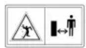
3a BpeMe Ha KoceHeTo Dpyrnte Iuza, Oco6eHo Deua n KINBOTn, Tpe6a Da ce dpKat NpaJneKy oI pa60THOTo npdaueje.
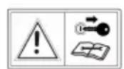
IpeodpkyBaBe n nonpaBkn 3BLeyeTe ro KOHTaKTTHNOT Kny!
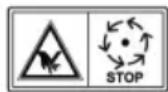
BHHMaHHe onaCHoc! DpKTe rI noJaIeKy paueTe n Ho3eTe oI anaTkata 3a ceYe!
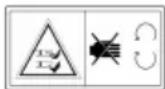
Да He ce BO3n Ha CTpMHINHnoroneMn od 10^ (18%)
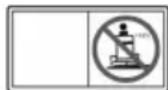
OnachocT: He ra3eTe obnde!
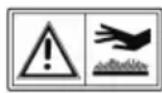
OnachocT od n3ropeHnI npaI TOpII NOBpHH!
2.4 Be36eHocn n 3aHTnTHn ypeNi
I PENEYPENEYBAHbE! OnacnocT oD OTCTpaHeTN NIN MaHInyInpAHH 3aWHTTHN ypei! Ce 3a6paHyBa cekakBa pa6oTa co OTCTpaHeTN NIN MaHInyInpAHH 3aWHTTHN ypei. DepeKTHnTe 3aWHTTHN ypei Mopa BeHaaw Da ce nonpaBat NIN 3aMeHaT!
Bo 3aunntne ype nce B6pojybaaT nped c:
KoHTaKeTH npeKNHyBaay 3a KoUHnIaTa
KoHTaKTeh npeKNHyBauch 3a anaTkata 3a KOceHe
KoHTaKTEn IpeKENHyBauch 3a KOpnata 3a co6npaHe TpeBa
KoHTaKTHe npeKNHyBaucha cENuTeTo
Kanaun Ha anaTkaTa 3a KoceHe
KoHTaKTHeN IpeKENHyBaU 3a KaHaNoT 3a NcΦpnyBaHbE
2.5Пергелд на пониворOT (01)
Бр.Енемп
1BoJah
2 Ta6na co nHcTpymeHTn
3 PedaJa 3a KoueHe
4 Kanak Ha MOTOPOT
Бр.Енемп
5 AKTINBnpaHBe Ha MeHyBaYOT 3aHaHa3aD
6 AKTINBnpaHBe Ha MeHyBaYOT 3a HaHaAnpei
7AataKa 3a KoceHe
8 MeHyBaHBe Ha BucnHaTa Ha CeYeHe
9 Ppemocnua Ha MeHyBaayot
10 CeH3Op Ha KOpnata 3a co6npahe TpeBa
11 AkTbBpaHBe Ha Kopnata
12 Kopna 3a co6upahe TpeBa
13 CeiWTe Ha BO3aOT
14 EJektpnHObaKTNBnpaHe Ha Kopnata*
15Ioc3a3aknyyBaBe 3a neJaNaTa 3a KoyeHe
16 Temnomat pauka*
*I3BeI6aTaBapuraN3aBnCOnoMDoJeIOT
Kora MOTOPOT He pa6oTH:
npi MHORY nCnpa3HeT akMyNaTop.
HanomeHa: Ipu 3acemyBaHe Ha o8oJ uHukamop no6apajme cneujuua3upaHa pa6omunHuca!
03/3 kora ke ce hannn Koprata 3a co6upahe TpeBa.

Icnpa3HeTe ja Kopnata 3a co6npahe TpeBa!
03/4 Kora ke ce Bknyu anatkaTa 3a KoceHbe.

03/6 Kora anaTkata 3a KOceHe Ke ce aKTNBnpa 3a BO3eHbe HaHa3a.

03/7 npn cmmhata Kopna 3a co6upahe TpeBa nn Kora nctata He e
npOnncho 3aTBopeHa.
03/8 npn BknyeHn paobn.

03/9 Kora ke ce npuHcHe KoHncaTa n npn 3aKnUyeHa KoHnla.

03/10 kora BO peepoapot mma cmo yuTe OKny 1,5 nItpn Ha
npeocTaHaTo rOpNo.
03/11 Kora HNBOTo Ha MacNo e NOD eNDHO OndeHNO HNBO.

03/12 ako Bo3aOT CnepHyBa OJ TpaKTopoT Kora:
MOtOpOT pa60Tu (KoUHncaTa e 3aKnyueHa)
5.3 Pepana 3a KoUHnua n Kynnyhr (05)
KouHnua: Co ueIocHo npITnCKaHe Ha neIaIata 3a KoueHe (05/1) HADony, KOUHnUaTb BInjae Ha MeHyBaHT a TpaKTOpOT KoU.
Kochnuca 3a napknupahe: Co nobkeybahe Ha loctot 3a 3aknyubahe (05/1)Ha harope Doideka ce npntncka nedaIata 3a Kooyebe (05/2)ce 3aknyba Koynuata. Co NOBTOPO npNTnCKaHe Ha neDaIata 3a KooyeBe, Kochnuata ce OTnyuTa.
5.4 PaKyBaHbe co MeHyBaYOT (6p3nHa Ha BO3eHBe) (04)
TpaKTopTe 3a KoceHe TpeBa ce onpeMeH co HOKeH XnIpoCTaTNUeH MeHyBaU.
Hekon moJeJI neOpemEn Co TemnOMaT.
Ima DBe Noc6Hn NeaJIH Na Deecho 3a BO3eHbe HaHaIpeN HaHa3aI.
| Hacoka Ha BO3e№ | Опис |
| Hаразд Путисhevе ja Decина тпеда (04/2), за за BOЗITE наразд. | |
| Hазад Путисhevе ja Левая педа (04/1), за за BOЗITE наразд. Наломена: Алатka差别а за косеце, искльецам akо有很大псисны само педа лота за BOЗЕ наразд. Косеце р�и BOЗЕ ваназад: Видп Позаимея 7.5.5 "Косець co mpakморскам косUILKA", смраза 511. | |
5.5 HoxkexnnpocTaTuHmehyBaay (04, 05)
HoxhnoT xuipocTaTuueH MeHyBaU ce aKtubpa npeky DBe neDaun (04/1 n 04/2).
3a noarahe npBO OTnywTeTe ja KoUHncaTa 3a napKupaBe (05/2)doNeKa pa6oTu MoTOpOT a noToa Hara3HeTe ja neJaIaNaTa (04/2)3a Bo3eHe HaHaPeD nnneJaIaNata (04/1)3a Bo3eHe HaHa3a. KOnKy wTo nOdaNeky ja npITnckate neJaIaNata ToKy no6p3O Bo3nTe BO n36paHaTa Hacoka.
Bozehe hahane: Pnntnche te ja Ha dechata ctpaHa hAdbopeuHata neDana (04/2).
Bo3eHbe Hana3aI: PnTncHeTe ja Ha deChata cTpaHa BHaTpewHaTa neAna (04/1).
5.6 PaKyBaHe co anaTkata 3a KoceHe (06)
IopeCyBaHe Ha BnCnHaTa Ha KocHe
AlaTkaTa 3a KoceHe Ha TpaKTopoT MoKe Da ce peryInpa BO NOBeKe CTeNEH BO BnCnHa co eHa paUka (06/2) DeCHO NOKpaj CeINuTeTo Ha BO3aOT.
1.ПиДВИЖeTe ja paЧКaТа 3a perулраБe (06/2)Bo cakHaTа HacOka.PaЧКaТа Ha NaDOny 3NaUHnCkBa BucNHa Ha KocHe, paЧКaТa Ha Harope 3NaUHrOJIeMa BucNHa Ha KocHe.
BkIyBaHe Ha aNaTkata 3a KoceHbe
EJIeKtpnHOb BknyuBaHbe:Bo pernohot Ha Ta6nata co nHCTpyMeHTn ce Haora eDeH npeknHyBauch 02/5).BknyuTe ja co Hero anatkata 3a KoceHe (no3nuija,1").
6 NUYUHTAHE BO YNOTPEBA
PNEyPENyBAHbE!OnachoctnoD HeueIocHO MOHTnpaBe!TpaKTopcKaTa KocnkaHe cMee Da ce KopncTn nped Da 6nde ueLoocHO MOHTnpaHa! Hapabete rCtTe MOHTaxHN pa6OTn KOuSTO ce ONUsAHN BO yNaTCTBOTO 3a MOHTaxa.Bo cnuyaj Ha COMHeBaHe nped nyuTaHBeTO BO yNoTppe6a npaawte CtpyuHo Nlue daNN MOHTaxaTa e npabInHO Hapabeha! PpOBepe TaNN Ce npNCyTHn CNTe 6e36eHOCnN 3aWTnTHn UpeNi DaNN Ce FyHKUOHaJIHn!
6.1 NpOBePkHa anaTkata 3a KoceHbe
Ipei ynoTpe6a Tpe6a cekoraa da ce npOBepn CO Bn3yeHn KaHTpOJa DaNN aNaTkata 3a KOceHe, 3aBPTKITE 3a PnUcBpCTyBaHe n CeNaTa eDHHuca 3a KOceHe ce NcTPOWeHn IIN OoTeTeHn. 3a N36erHyBaBe Ha HEn36aJaanCnpaHOCT NcTPOWeHn EIN OoTeTeHnTe HOKeBn Mopa Da ce 3aMeHaT CO HOBN.
6.2 POnHeBe co macJo
Ipei npBTo nyuTaHe Bo pa6oTa MOTOPOT Mopa Da ce HanoJIHn CO MacNo. 3aToa 3eMeTe ro BO npEdBn yNaTCTBOTo Ha npOn3BOJNTeNt Ha MOTOPOT. ImajTe BO npEdBn DeKa HNBOTO Ha MacNo Tpe6a Da CE KOHTpOJnPa BO peoBn pacTojaHnJa N Da Ce HApONOJIHn MacNo aKO e IOTpe6Ho.
6.3 POnHeBe co ropuBO (09)
PNEUYPENEYBAHbE!OnacHOt nppaKyBaHbeto co ropno!TopnBOTo e IecHO3aapanbo. POnHeTe ro pe3epBoapOT 3a ropNoBCAMo Ha OTBopeHo! He nyweTe! He nonHeTeropnBO pnp DBNKeUKNI TOnOJ MOTOP!
3a nonhebe KOpncTeTe COOdbetHa INKa NnUcpeBO 3a nonHebe 3a Da He ce nctypn ropBO Ha MOTOPOT, KyKNUTeTO nn Ha 3emjata.
Od 6e36eHOCn npuHHn KaaYeTo Ha pe3epBoaPot 3a rOpNBO nDpyrTe KaanHbHa pe3epBoaP Tpe6a Da ce 3aMeHaT npn OwTeTyBaHe.
ДOKOLКУ Има петechу РорИВ He CМeE Да С СтAPТУВa MOTОР. ТраKTOPOT Tpe6a Да С OTCTpaHи OD MeCTOTO 3araDEHo CO ROPИВ a ИСТуЧЕНо TROPИВ MОра Дa CE BшMyka N ИЗБпше CO Кпа OД ПОДТ, MOTОРИ КУКИШТЕТО.
Tpe6a da ce n36eHHe cekakOB o6n3a CTapTuBaHBe cédoKeHa He nCnapaT napente od TropNBOTO.
TOpuBToUyBaJTe ro cAmo BO npEbnEnHnTe caDobN.
KopncTeTe 6e3oJIOBEN 6eH3nH, MNH. ROZ 91.
PonHeBe Ha pe3epBoapoT
1.ИcknyeTe ja aKO Tpe6a TpaKTOpckaTа KOCNJIka I N3BJIeYeTe FO KOHTaKTHNOT Kny 3apaI INCrypHOCT.
2. Поуекajtedoideka He ce n3naMamKy MOTOPOT (OnachocT od ekcnnoJapn 3anaheNo roPBO!).
3. Ппуншени На полonska.Tа OД Канayeto Ha pe3epBoapot (09/1).
4. Cbptete ja noknonkata od kanaeTo Ha pe3epBoaopT (09/1)Ha harope. Noknonkata od kanaeTo Ha pe3epBoaopT (09/1) ce OTKnyyBa.
5. OTbopete ro kanaeTo ha pe3epBoapot (09/2) n HanoHete ro rOpBOTO. HanomeHa: N36eaHybajme npenOnHyBaHe Ha pe3epBoapom 3a 2Opue!
6. 3aTbopeTe ro kanaYeTo 3a pe3epBoapot (09/2).
7. 3aTbOpete ja noklonkata oJ kanayeto Ha pe3epBoapot (09/1), Taka wTo da ce BrnaBn.
6.4 Поберka Ha npntucokot Ha rymnte
KoHTpOIpaJTe ro npNTucOKOT Ha rymnte BO peoBn paCToJaHja.
IcHTajTe ro nOte6HnOT BO3dyuWeH npTUCOK Ha rymite (npenopaka 1 bar).
HANOMEHA 1 PSI = 0,07 bar.
Ipyntncokot Ha rymTe moKe da ce KOHTpOnpa co BO6nHa HoxHa nymna 3a Bo3dyx I da ce HaDoONHn BO3dyX.
6.5ПикayBaHbeHaKOpnata3aCo6npaHBe TpeBa(10-13)
TpaKTOpCKnTe KocnKc Ce nCnpaCyBaat Co Kopna 3a coBnPaHe TpeBa. NmajTe Bo npEbnDyI DeKa CnKnTe MoKe Da ce pa3NkYBaAT MaNky OJ opRHaNoT.
IopdecyBaHe Ha HndnKaTopoT 3a HanoJIHeTOcT Ha Kopnata 3a cObpaBe TpeBa
HnIkaTopoT 3a HanoJIHeTOcJT aByBa npeky eHa cIneHa Kora Tpe6a Da ce Ncnpa3Hn Kopnata 3a co6npaHe TpeBa.
Hdikatopot 3a HanohtocT MoKe Da ce
noecn BO 6 no3uIN BO 3aBnchoCT OcOCTABOT
Ha OTKOCOT. Pn cyb OTKOC Nomectete Ro
HHdkatopot 3a HanohtocT BO NOMaNTe
no3uIN. Pn MOKAP nn BnaJKeH OTKOC
nocecTe ro HHdkatopot 3a HanohtocT Ha
nooJro. Co Toa ce BnJae Bp3 NoIHeBeTo Ha
kopnata 3a co6npahe TpeBa.
1.ИcknyteToMOTOpOT(BnDnNoaJa6e7.4 "CmapmyBaHe u ucknyyBaHe Ha Momopom",cmpaHa 509).
2. CmHete ja Kopnata 3a cobupahe TpeBa (Bnu Nioaabe 8.1 "UcmeHe Ha Kopnama 3a cobupahe mpeBa", cmpHa 513).
3. NocTaBete ro HnDnKaTOpOT 3a HAnONHeTOCT (10/1) Ha otKocot (10/a), cé DoNeKa He ce fNkCnpa BO cakaHaTa No3nJa.
4. NOBTOPHO 3aKaHeTe ja Kopnata 3a co6npahe TpeBa.
3akaute ja Kopnata 3a co6npahe TpeBa.
- Φатete ja kopnata 3a co6upahe TpeBa co eHa paka 3a paKaTAt OJ Kopnata (11/1) a co DpyraTa paka Ha OTBOPOT 3a npdpxyBaHe Ha 3aHaTAt CtpaHa (11/2).
2.Положete ja kopnata 3a co6upahe TpeBa cnmetpnuHo Ha BOdInkata (11/3). - Habane ja kopnata 3a co6npahe TpeBa co pyrata paka MaIky Ha Hanpei (12) taKa ITO da ce fNknpa npedHnot den Ha Kopnata 3a co6npahe TpeBa.
-
Cbptete ja Kopnata 3a co6npahe TpeBa NOBTOPO Ha HADONY (13/a).
-
Поверете то.ToHOTо пиционраье на Корпanta 3a coираьe TpeBa.
6.6 Поберka на 6e36eHocnTe урдн
Бe36eHocnTe ypeiMopa da ce npOBepaT ppei cekoe cTapTuBaHbe Ha TpaKTopcKaTa KocuIka.
PNEyPENEYBAHbE!OnacnoCT npnpoBepkataHa6e36eHocnTe ypeN!
Be36eHocHTe ypeiN ce Do3BOJehn 3a npOBepka camo od ceiNtTeTo Ha BO3aOT N KORA Hema dpyrN Iuca uN JxIBOTHn BO 6IINHa!
HanpaBeTe rN cHTe npOBepKn Ha pamHa noIora Taka uTO TpaKTOpCKaTa KocnJa Da He MoKe HecaKaHO da Ce Tpkana.
6.6.1 Поберka Ha KOHTaKTHNOT п配电инвач 3a КОЧицаТа
KoHTaKTTHNOT npeKNHyBaU 3a KoUHnCaTa rapaHTnpa DeKa MOTopoT He MoKe Da ce cTapTyBa aKO He Ce npITNCHe KOUHnCaTa.
- MoToPoTe uNcKnyuEn.
- CeHHeTe Ha ceINuTeTo Ha BO3aUoT.
- OTnyuTeTe ja KoUHncaTa 3a napKnpaBe co npTnCKaHe Ha neJaIata 3a KoUHncaTa (05/1).
4.ObndeTe ce da ro cTapTyBaTe MOTOPOT (KoHTaKTEn Knyu BO N03nUja III).
HANOMEHA MoTopoT He cMee da CTapTyBa!
6.6.2ПюверкаHa KOHTaKTHNOt npeKNHyBaay3a aNaTkaTa 3a KOCeHbE
KoHTaKTHnOT IpeKNHyBauch 3a aNaTkata 3a KocHe rapaHTnpa DeKa MOTOpOT He MoKe Da Ce CTapTyBa aKO e aKTbBnPaHa aNaTkata 3a KocHe.
- MoToPoTe uNcKnyuEh.
- CeHHeTe Ha ceINiHTeTo Ha BO3aOTo.
- Пптушисте ѳ пелдана за кочев (05/1) и akтувирajte ѳ кочница за паркURA (05/2).
- Bknyute ja anaTkata 3a koche (02/5, no3njuja ,1").
5.ObndeTe ce da ro cTapTyBaTe MoTOpOT (KoHTaKTeh Knyu BO No3nCiJa III).
HANOMEHA MoTopoT He cMee da CTapTyBa!
6.6.3 Пюверka на КонтактноТпpeкнHyBaч 3a ceишTeTO
KoHTaKTHnOT npeKNHyBaU 3a ceNtTeTo rapaHTnpa DeKa MOTOpOT ce NCKnyuBa IITOM Hema HkoJ Ha ceNtTeTO Ha OepaTOpOT KOra e BKnyeHa aIaNkata 3a KoceHe.
- CeHHeTe Ha ceINuTeTo Ha BO3aUoT.
2.ПиТиСнeTe ja NeДаЛaТа 3a KoUeHbe (05/1) n aKTHuBpajTe ja KOUHnIaTa 3a napKInpaHbe (05/2). - CtrapTyBajTe ro MOTOPOT n octaBeTe ro da BPTN co MaKcImaJIeH 6poj Ha BpTeJn.
- BknyeTe ja anaTkata 3a koche (02/5, no3njuja ,1").
- Понигichte ja Baшатужина od ceиштeto co Toa wTo Ke cTaHete (He cneryBajTe!).
HANOMEHA MoTopoT Mopa da ce ncknyu!
6.6.4 Пюверka Ha KOHTaKTTHNOT п配电инуньч Ha KОрпаТа 3a coбира№ ТpeBa
KoHTaKTHnOT npeKnHyBaH Na KopNaTa 3a coBpaHe TpeBa rapaHTnpa DeKa MOTOpOT ce NCKIyUBA DOKOJIky He e npaBnHO 3aKaueHa KopNaTa 3a coBpaHe TpeBa npN BknyeHa anatka 3a KOceHe.
- CeHHeTe Ha ceINuTeTo Ha BO3aUoT.
- Пи捜сichte ja падалata 3a кочьe (05/1) и akTNBupajte ja kOUHncaTa 3a napKnpahe (05/2).
- CtapTyBaJte ro MOTOpOT n octaBeTe ro da BPTN CO MaKcImaJIeH 6poj Ha BpTeKn.
- BknyeTe ja anatkata 3a KoceHe (02/5, no3njuja ,1").
5.Подигнеле ja MaNky npa3HaTа KOpna 3a co6npaHbe TpeBa nINn AKTNbupajTe ro npeknHyBaOY 3a OTBopaHbe.
HANOMEHA Motopot Mopa da ce ncknyu!
6.6.5ПроверкаHa KOHTaKTTHNOTп配电инвачHa KaHaJOT3ancфрлуВа№
KoHTaKTnOt IpeKInHyBaU Ha KaHaIOT 3a
NcΦpnyBaHBe rapaHTnpa DeKa TpaKTOpCKaTa
KocnJa He Ce CTapTyBa PnI DeMOHTnpaH KaHaJ
3a NcΦpnyBaHBe.
-
CmHyBaHbe Ha Kopnata 3a co6npaHbe TpeBa.
-
OTeTaHeTe ro KaHaIOT 3a nCpPnyBaHBe (18/2).
- CeDHeTe Ha ceDnWTeTo Ha BO3aOTo.
- Пи捜сichte ja nepaata 3a koyebe (05/1) n akTbnpajte ja kOuHncaTa 3a napKupahe (05/2).
- CtapTyBajte ro MOTopoT.
HANOMEHA Motopot He cMee da CTapTyBa!
7 PABOTEHE CO TPAKTOPOT
I P E D U N P E D Y B A H E! O n a c h o c t n
napn HeoBOHNO no3HaBaHe Ha TpaKTopcKaTakocnka! Lepnocho npouHTajTe ro ynatCTBTO 3a pa6To nped da noyheTe! BnImabajTe oc6eHo Ha cnte 6e36eHocn HanomeH! CobecHO BPweTe rN cnte MOHTaXn pa60Tu n cnte pa60Tu 3a nyuTaHBe BO pa60Ta. Bo cnuyaj Ha comHeBaHe npawajTe ro npoun3BOAnTeJOT!
7.1 OchOBHn noIroTBuTeJIHN MepKu
IpnKocHe CeKOraH HocTe TBpDn YeBn IdoTn NaHTaONH. HkOraH He KocTe 6ocn nn CO OTbOpEn CaHaJI.
IpoBepTe ro BO ueNoCT TepeHOT Ha KoJ Ke ce KopnCTn TpaKTOpCKaTa KocnIka. OTrpaHeTe r n CITE KaMeHa, PpaKu, KnU, Kocku IpyrTuIn TeNa KOnUTo 6n MoKeJe Da ce 3aΦaT n OTpPnA. UcTo TaKa n 3a BpeMe Ha KoCeHbETo Tpe6a Da ce BHImaBa Ha TyIn TeNa.
HanpaBete rncuTe pa6oTn konuTo ce onnuaHn BO npTaBeTo Bo pa6oTa. Oba Baxn ocObeHo 3a npOBepKaTa Ha 6e36eHNocHTe ypeN.
3a Bneuehe Ha TOBAPn KOpNCTeTe ja cAmo Kykata 3a Bneuehe! He ro NaDMnHyBaJIte BEPTIKAJIHOTO ONTOBApyBaJIbe.
He e do3BOJEN TpaHCnOpT Ha npeMeTu Ha TpaKTOpCKaTa KocuJa!
7.2 KopncTeHe Ha DoaTaHa onpema
I PNEyPENEYBAHbE! OnacnocT od
NORpeuHa DoaTHa ONpema Hn NORpeuHo
KOpNCTeHe Ha DoaTHa ONpema! KopNCTeTe
CEKORAsw Camo OpunHaJIHa ONpema Ha
Ipon3BOJNTeJOT Ha TpaKTopo! NOnHTyBajTe rN
IponCITE 3a KOpNCTeHe BO pInIOxKeHTo
yNaTCTBO 3a pa6Ota!
Ipeky ynoTpe6aTa Ha Heo3BoneHa DoaTHa
onpema nn noRpeuHaTa ynoTpe6a Ha onpema
MOxke Da HactaHaT Rolemn OnacHocTn 3a
Oepatopot n TpeTu Nua.TpaKTopcKaTa
Kocnilka Moxke Da ce poeontobapn. Toa Moxke da
doBeDe Do TeWKn HecpeKn.
7.3 Typkahe Ha TpaKTopckaTa KocnIka (15, 16)
BHIMAHHE! Onachoc npn TypkaheTo no KocHH! Typkajte ja TpaKTopckata KocNkacamo Ha Xopn3oHTaHn NOBpHInH! Ha KocHH TpaKTopckata KocNkA 6n MoXeNa HeKOHTpoJInpaHO da ce cTpkaHa HADony.
Kaj Hoxhen XnpocTaTuHc MeHyBaU
IpeMoChata paKa (15/1) ce Haora BO 3aHaTa DeChata yTpOJa 3a Tpkanoto.
Дeблokираье на премочиcaТа кaj T3-MeHyBaU (TIN: T15, T16, T18):
1.ИЗВЕЧЕТЯДпемочаразka(15/1)изakayete jaHaHarope(16).
2. Ocnoobode ja kouhnucaTa.
TpaKTopcKaTa KocNJa MoKe cera Da ce Typka.
BknyyBaHe/NUCKnyCyBaHe Ha TEMnOMaTOT:
CbpTeJe paaykata (02/3) Ha harope. Temnomamom ce eknyya.
CbpTeJe paKaTa (02/3) Ha HAdony. Temnomamom ce ucknyyba.
7.5.4 Bo3eHbe n KoceHe Ha cTpMHHH
I PEPUYPEDYBAE! Onacnoct od
rpeu npn BO3eHe Ha cTpmHnH! Pn
BO3eHe Ha cTpmHnH Tpe6a Da ce obpaTH
IOce6HO BHMaHne! Hema TaKBO HeWTo Kako 6e36eHa" cTpmHnHa. Oco6eHO NOHTyBajTe rCneHNTE 6e36eHocn HAnOMeH! OTkayete ja anatkata 3a KOceHe n DonONHtEnHaTa ONpema aKO TPKaNaTa IpeBpTyBaAT INN aKO BO3INOTO OTkaxe KORA BO3ITE NO cTpmHnHa. Notoa
HanyuTeTe ja cTpmHnHaTA BO 6abHo HADONHO
BO3eHe dONx Na'ayKaTa LInHja! NOnHata Kopna 3a co6npaBe TpeBa ja 3roJeMyBa ONachOCTa 3a IpeBpTyBaHe Ha TpaKTOpCKaTa KocuNka ppeky Hej3nHaTa TeXnHa!
-Да He ce BO3n Ha CTpmHnHn NoroJemn Od 10^ (18%).Пример:Toa odroBapa Ha 18 cm pa3nka Bo BnCnHa Ha DoJxHa oD 1 MeTap.
Bo3eTepaMHomepHo.
He KooyTe HaeDHa.
OdpxByajTe Hnka 6p3nHa Ha Bo3eHbe.
He Bo3eTe nonpeky CtpMHnHaTa.
He 3a6p3yBaJte HaedHa.
YnpabyBajte pAMHomepHo.
7.5.5 KocHe co TpaTOpckata Kocnka
Ppnilarodete ja 6p3nHaT ha BO3eHe cnopeyCNOBHTa Ha TpeBnKOT co zel da noCTnHete uNCT pe3yNTaT ha KOceHe. N36epTe HajMHORY 2/3 od MOxHaTa 6p3nHa Ha BO3eHe Ha neJaNaTa Kora KocuTe. MaKcImaHata 6p3nHa Ha TpaKTopoT e NCKnyuHO HameHeta 3a BO3eHe 6e3 BklyueHa aIaTka 3a KOceHe.
Bo HopmaJIeH cnUyaj BucnHaTa Ha KocHeB e n3HecyBa 4 - 5 cm.Toa OndroBapa Ha BToPnOT nn TpeTnot.3acek OD perynipaheTo Ha BucnHata (06/2).PpN BlaJHa N Mokpa TpeBa KOCete Co NOBnCOKa BucnHa Ha KocHeB.
Kaj MHory Bucoka TpeBa, noxekHo e da ce NOMHe BO Dba npemHa. CTabete ja anaTkata 3a KocHe Ha MaKcMaJHa BucnHa Ha KocHe npn PpBnot npemH. PpN BTOpNt npemH MOKeTe nToa Da ja HaMaJIne Ha cakaHaTa BucnHa.
7.5.5.1 BknyBaHe Ha aJaTkata 3a KoceHb
HANOMEHA Anatkata 3a Kocebe Cmee Da ce Bknyu Dypu OTkako MOTOPe 3arpeah OKony eHa MNyTa! PnBklyuBaHeTo Ha anatkata 3a Kocebe TpaKTopcKaTa Kocnka He 6n TpebaNo Da CTOn BO BnCoka TpeBa.
- CtapTybajre ro MOTopoT.
2.ПомecTeTe ro perynatopot (02/2) 3a 6pojOT Ha BpTeKn Ha MOTOPOT BO pa6oTHa NO3nCnJa.
3. Ctabete ja anaTkaTa 3a KoceHe Ha HajBnCOkata BucnHa Ha KoceHe (06/2).
4. Bknyte ja anaatkata 3a koche co npeknonhata cklonka (02/5, no3njuja "1").
5. NocTaBeTe ja cakaHaTa BnCnHa Ha KoCeHbe co paKaTata (06/2).
6. Ctabete ja TpaKTopcKaTa Kocnka Bo DnHexe.
7.5.5.2 KocHe npn BO3eHBe HaHa3a
HANOMEHA AnaTkata 3a KoceHe e NCKnyeHa aKO e npTnCHaTa cAmO neJaNaTa 3a BO3eHe HaHa3a.
1.ПиТиСHTeTo ro konUeTo „KocHeHaHa3aD" (02/6)И BO pOK OД 5 ceKHyHnI npITnCHTe ja NeJaIaTa 3a BO3eHbE HaHa3aD(04/1).
PNEpyPDEyBAHbE!OnachocT od He3roI npi KoceHe HaHa3aI!O6paTeBHNMaHne HaNoDpaJJeTO 3aB Bac KOra Kocnte HaHa3aI!KoCeHe HaHa3aIcMo aKO e nOTpe6Ho!
7.5.5.3 NcknyBaHe Ha aJaTkata 3a KOceHe
PNEyPENyBAHbE!OnacnocT od BPTINBn HOxEBN!Kora HOxEBNTe 3a ceyebe ce yUte Ce BpTa, Tne MOKe Da rN Inceuat paate N Ho3e!Iopadn Toa,paTe N Ho3eT dpKeTe rN HAcTpAna oD ceunata!
- NcknyeTe ja anaTkata 3a Kocebe co npeknonHaTa cKnonka (02/5, no3nuija "0" - Anatkata 3a KoceBe MoKe Da ce Ncknyu Kora TpaKTopoTe BO MnpyBaHe N Kora Ce Bo3N.
PNEyPENEYBAHbE!OnachocT od NOBpeDa oNcOpJIeHN PpeMeTu!PnnpemHyBaHe Ha YakaJHo-NEcOKnBu NOBpuHHMOKe Da CE BOJIeUaT PpeMeTu BO DnJXeKaTa aNatka 3a KocHe I NoToa Da Ce NcOpnat.
CekoraU NCKnyuBajTe ja anaTkata 3a KOceHBe Kora He BO3nTe No TpeBHN NOBpUnHn.
7.5.5.7 KoceHe Ha BnCoka TpeBa
Kocete co nobucoka noCTaKa 3a BnCnHa Na KocHe Kora TpeBaTa e Nobucoka od HopMaJIHo nn Kora e BlaxHa. IToTa yUte edHaW NCKoTe ja TpeBaTa co NoHnCKaTa, HopMaJHa NOCTaKa.
7.5.5.8 OdpKyBaHbe Ha HOXOT 3a ceYeHe
IorpnkeTe ce HOKOT 3a ceeHe da OCTaHe octap 3a BpeMe Ha ZeJaTa Ce3OHa Ha KOceHe 3a Da N36erHHeTe OTKNHyBaHe I packHyBaHe Ha TpeBKnTe. OTKNHaTne TpeBKn Ce KaFeaBn Ha pa6oBnTe. Co Toa ce HamaNyBa HNBHOTo pacteHe n rno npaBn TpeBHKOT NOJIOKeH Ha 6oJeCTn.
IpoBepTe Hn HOKeBnTe 3a ceYeBe 3a octpHa n 3Haun Ha nCTpoWyBaHe nn OoTetyBaBe no cekoja ynoTpe6a! Ako e notpe6Ho cepBncnPajTe n BeDaH.
Ipn 3aMeHa Ha HOKeBnTe KOpNCteTe cMo opuHnHaJIH pe3epBn HOKeBn.
8 YNCTEHe HA TPAKTOPCKATA KOCNJKA
3a ONTUMaHa 4yHKuJa I DOJIg JKNBOTeH BEK TpaKTopcKaTa Kocnka Mopa peoBHO da ce YNCTN.
No cekoe KopncTeHe nCnuCteTe ja TpaKTopckata Kocnka O, HaneHEn HeuNCTOTn.
3a qute He Kopnte Te ype 3a qutebe noBnCOK npTncok. BodeHnot mna3 od ype3a qnteHe nD BnCOK npTncok nnrpaHapcko UpeBO MOKe da ro OwTeTneEneKtpuHNOt cnCTem nn Naepute.
Oco6eHO BHMaBajTe Da He Dojde BOda BO KOHTaKT CO MOTOPOT, MeHyBaHOT N TpkaIcaTa 3a npyeCmepyBaBe, KaKo N ZeJInot eJeKTPnueh CnCTem.
I PEPDyPENEYBAHbE! Onachoctn npu ChtebeTo! Ipn cnte paBOTn 3a chtehe Baxn:
IcknyeTe ro MOTOPOT n 3BneyeTe ro KOHTaKTTHOT Knyu.
OTCTpaHete ro KOHeKTopoT Ha CBeKnUkata.
OTCTpaHETnTe 3aWHTTHypeDn nopadnyuHcTeHbeto Mopa NOBTOHa ce MOHTnpaaTno YNCTeHbeto.
ONACHOCT OД ИЗГОЕнцИ:Чисте joТракторскata Косилka Дури OTКAKO Ke ceизлади.МOTOPOT,MeHyBaOTипдушУвачOT Ha 3ByKOT ceMHORY TOnПИ!
ONACHOCT OJ CEYEHbE: Pnp pa6oTeHbE Ha aIaTKnTe 3a ceYebe BHMAbajTe Ha OCTpnte HOKeBn. Kaj aIaTKn 3a KoceHe co NOBeKe OD eNHO CEuNIO, DBXKeHbTo Ha eNHO CEuNIO MOKe Da npedN3BnKa DvXKeHbE n Ha dpyrOto!
8.1 YncteHe Ha Kopnata 3a co6npaHb e TpeBa
Cnytete ja kopnata 3a co6npahe TpeBa n
ncwnpuajTe ja od BHaTpe n HAdBOP co cpeBO
3a BOda. NouBPCTO haneHEnTE HeuNCTOTNI
Mopa BHMaTeJHO da ce nctpyraat, Ha npImep
co YETka. Kaj KopnTe 3a co6npahe TpeBa co
TKaeha HabIaka BHMaBajTe OcOeHo Ha Toa da
He CE OwTeTN TkaeHHHaTa.
HANIOMEHA IpeD YnCTeBcTo
ncpaa3HeTe ja Kopnata 3a co6npaBe TpeBa KaKo
UTo e OnnuHo. EHa nonHa Kopna 3a
co6npaBe TpeBa e npemHory Teuka 3a da 6n
MOKeJe 6e36eNo da ja CmHete.
CmHyBaBe Ha Kopna 3a co6upaBe TpeBa
1.ИcknyteToMOTopoT.
2. JIeCHO noDnHHeTe ja Kopnata 3a coBipaBe TpeBa.
3.ИЗваде Te ja Kopnata 3a co6upahe TpeBa Ha Harope.
CmHyBaHe Ha eNeKtpnUHO KOHTpOlnpaHaTa Kopna 3a co6npaBe TpeBa
He npedn3BvkyBajTe kpaTOK cnoj Ha TepMNHaJIte.
PonHeBe Ha akymyNaTopoT
PonHeBeTo e noTpe6Ho:
PpeD cKnapaheTo 3a 3mMckTa nay3a.
Pn noJIOJRO BpeMe Ha MnpyBaHe HaypeoT (noJOnro oD 3 Meceu).
I PEPdYPepyBAHbE! Onachoct od HnpaBnHNo nnonHeBa ha akymylaTopoT!
CTpyjata 3a nonHebe Ha nonHaoyet He cMee da HAdMinHyBa 5 A a HanoHOT 3a nonHebe MoKe da 6nnde camo mAc.14,4 V.Pp nOBUCOK HAnOH Ha nonHebe NoCTOn OnaCHOCT OJ EKCnNo3nJa Ha akymyNatopo! Cekorau N3BaTe ro KOHTaKTTHNt Knyu nped Da noUHeTe da paBoTnte Ha akymyNatopoT.
Bn npenopaybame da ro noHNHTe
akymyIaTOPOT, wTO He nponyuTa racOBn Ha
koJ He My Tpe6a OndKyuBaHe, KopncTejKn
cneunjaHc COoDBeTeH NOHauch (KoJ MOKe Da ce
do6ne npeky cneunjaJIaN3npaHn npOdaBnU).
PouHTyBaJTe ro yNaTcTBOTO 3a yNoTpe6a Ha
pOn3BOIDNTeJIoT Ha NoJHaOT pPeD n 3a BpeMe
Ha NoJIHeBe Ha akymyIaTOPOT.
BHIMAHHE! OnachocT od kpaTOK cnoj!
3a da n36erHeTe KpaTOK cnoj, cekoraH HajnpBO OdBoJTe ro HeratNBHNOT KaBen (-) od akymyIaTOPoT I NOBTOPO NoBP3eTe Ro KaKO nocpeDen! Cekorau n3BaTe Ro KOHTAKTHNO T kny nped Da noHete Da pa60NTe Ha akymyIaTOPoT!
1.ИЗВЕЧЕТо KOHTАКTHНОТ KNYU(02/4).
2. OTbopete ro kanakot Ha MOTopoT.
3.ПоврзeteгиКнемпe Ha noHaayot co TepMinHaJIte Ha akymyIaTopOT.
HANOMEHA O6pHeTe BHNMaHne Ha noJapuTeTOT:
LpBeHa KEma = No3ntBHeTepMnHaJ (+)
LpHa KneMa = HeraTUBen TepMHaJ(-)
4.Поврзete ro nonhaOT co ctpyjHaTa Мраи BKnyeTe ro.
9.5 OTeTpaHyBaHe Ha anaTkaTa 3a KoceHbe
AaTkata 3a KoeHe Mopa Da ce N3BaDi co ZeI 3a Da ce KopnCTn TpaKTopoT 3a pacnctyBaHbE Ha CHER I 3a IpomeHa Ha KNHeCTNOT pEmeH.
-
3aBpTeTe ro BOnaHOT Ha ueNoCHO JIeBO 3aknyuBaHe (32).
-
Otrpahe Te ja Kopnata 3a co6upahe TpeBa (33).
3.ИЗваде Te ro KaHAnOT 3a nCфрлУВа№ (18). - OndbptTe ja cunHnIapckaTa 3abTpKa (34) Ha dpkaoyT ha kaHaJOT co 5-6 BpTeHa.
- CnyuTeTe ja anatkata 3a KoceHe Ha HajHnCKaTa NoCTaBka (35).
- OTKaueTe ro BJeuHnO T fep Ha aJaTkaTa 3a KoceHe (36).
- Ctabete ja anaTkata 3a KOceHe NOBTOPO rope (37).
- OTkaYeTe ro KaHaJNot Ha KJIInHeCTNt peMeH (38).
- OTKaueTe ro KInHeCTnOT peMeH oJ Waj6HaTa 3a KInHeCTnOT peMeH Ha MOTopOT (39).
- NOBTOPHO cnyuTete ja anatkata 3a KOceHe Ha Hajnckata noCTabka (40).
- OTCpaHeTe r4-Te pHHOBu 3a 3aKJIyUyBaHBe Ha qNKcaTopHTe oJ aJaTkaTa 3a KoceHBe (41).
12.ИЗВЛЕЧЕТЯнФИКСАТОПNTЕпpeky6OJIцHNTe (41).
9.6 3aMeHa Ha KJIInHeCTnOT peMeH
- OndBpTeTe r6-Te 6e36eHocn HABpTK (24).
- OTkaYeTe rO KaHaJIOT Ha KJIINHeCTNtOp peMeH (25).
- Otkaute ja n otctpaHete ja dechaTa noklonka (26) Ha anatkata 3a Kocehe.
- Otkaute ja n otctpahe ta JneBaTa NOKIIONka (27) Ha anatkata 3a KOceHe.
- Iecho OndBpTeTe ja 3aBpTkata Ha 3aTe3HNOt BaJIjaK cIdoKeHa MoKe Da ce pa3HnKe KInHeCTNt peMeH (28).
6.ИЗваде Te Клпеснот ремен.
HANOMEHA BoDnKata n noLoX6aTa Ha KInHeCTNt peMeH ce pa3NIkyBa BO 3aBnCHOCT OJ TINOT. NoyTuBajTe ja HaneHnUcaTa co HAnOMeHn Ha aIaNkata 3a KOceHe.
CTabaHe Ha HOB KJINHECT pemeH
1.ПОJOKTeTo KINHeCTNOT pEmeH OKOJy IecHO OdBpTeHNOT 3aTe3eH BaJIjaK IN NOBTOPO 3aUpaPeTe To 3aTe3HNOr BAJIaK (30/31).
2. Полжete ro кинеспOT peMeH cnopepepeocneodot okoly BaJIaunite n 3ana3eTe ja BOДИКаТИ NOLOX6aTa Ha KIINHEcTNot peMeH.
10 TPAHCNOPT
Ipn TpaHcnpT Ha TpaKTopcKaTa KocnIka Co TpaHCnOpTHa ONpema (Ha np. npNKoIka 3a ABTomO6n), aIaNtKaTa 3a KoceHe Mopa Da ce NODpXn ODOZOnla Co cen Da ce HAmAn ONTOBAPyBaHbETo Ha 3aKaUyBaHbETo Ha aIaNtKaTa 3a KoceHe.
3a Bpeme Ha TpaHcnpT, npOBepTe daJIIn TpaHCnOpTHnte CpeICTBa IMaat DOBOJEn KaIauITe 3a TOBap N daJIIN COODBeTHO e PpiuBpcTeHa TpaKTOpCKaTa KocNIka.
11 CKJIaIbPAHbE
TpaKTOpCKaTa KocnKa Tpe6a Da ce napKnpa KaDe 3aWtTeHa Od BpeMeHcN BnJaHja,OCo6eHO Bnara,doXd NpOJrO u3IOxyBaHe Ha DnpeKTHa COHcEBA CBETnHa.
Hnkoraaw He ja cknadnapajTe TpaKTOpckaTa Kocnilka BO 3rpaJa co ropnBO Bo pe3epBoaopot aKO hMa NoteHunja 3a napeHTe OD ropNBOT da Dojat BO KOHTaKT CO OTBopeHn PnaMeHN IIN NCKPN. NapknpajTe ja TpaKTOpckaTa Kocnilka BO npocToPnKoIHTO ce CoODBeTHN 3a CKnadnapHe Ha MOTOPHn BO3nla.
Kora ja cknaipate TpaKTopckaTa Kocnilka 3a DOJIIN NepNOi, KaKO Ha npIMep Npeky 3nMa, NO MOxHOCt He Tpe6a Da ce cknaInpa co noJH pe3epBoap 3a rOpuBO. FopuBTo MoKe da nCnapi.
Ipei doJIoTpajHo CKJaAnpaHbe, ropNBOTo Tpe6a Da ce IcnyuTn OJ pe3epBoapOt n Kap6ypaTopoT co cen da ce 36erHe Co3daBaHbe Ha HacnaR KOeWTo MOKe Da IOBeDe Do np6JIemn npi CTapTyBaHbTe. KoHTaKTIpaJte ja BaWata CneuiJauN3npaHa pa6OTnHnUca 3a COBt.
12 NOMOISH BO CJIyuaJ HA DEΦEKTN
BHIMAHNE! OnachocT od nobpeda.
IpeMeTte co ocTp npaobn I camoBnKeKNTe DeNoBn Ha ypeDoT MoKe da DOBeDaT Do NOBpeN.
Pp npapobTuHa oDpxyBaHbe, Hera n uNCTeHe HocTe cekoraaw 3aWTTH paKaBnU!
HANOMEHA Bo cnyaj Ha depektn, KOIHTO He ce HabeDeHn BO TaBeNaTa nn Bue camITE He MOKeTe Da rN OTCTpaHnTE, o6paTeCe Do HaINOT KOpNCnKn CepBnC.
| Дeф ekт Причина Остраунье | ||
| MOTOPOT Ne пап. Нedingостаток на горив. Налочnéte сеервоарот; поеверete ja венилальna на розервоарот; поеверete сеервоарот; поеверete сеервоарот 3a рогив. | ||
| Лобно, Нechисто рорив, сато rорив BO pezerвоарот. | Секогаш користо сбжо рорив од чісту садови; Исwich�то сьарырговуп ( kapбурагоур (разотенпница на сныжбата зд корисни). | |
| ФильерOT 3a ВОздух e Нechис. Исwich�то сеервоарот 3a ВОздух (Вишиу упатстову оз равoting на мOTОР). | Пскирот SF 3A ВОздух e Hecicnt. Берншу Сеервоарот 3a ВОздух (Вишиу упатстову оз равoting на мOTОР). | |
| HEMA Искра 3a палег. Исwich�то сеервоарот ja сөкүчкatinga, замене jo coюba akо e пotрбно, поеверete ro kабелOT 3a палег, поеверete ro систemOT 3a палег (разотенпница на сныжбата зд корисни). | Пскирот SF 3A ВОздух e Hecicnt. Одberгете jo и сухete ja сөкүчкatinga. | |
| АнласерOT Ne phункционир. | Празен плс abakymunatop. Налочnéte ro akumunatoporot. | |
| БeбедносиOT р佩кинчын на сediштOTO на ВОздуOT He Функционир. | ||
| БeбедносиOT р佩кинчын на падалata за кочеge He Функционир. | ||
| Алatkata за кочеge e вklусан. | ||
| ОсигурвачOT на (+) кабелOT od akumunatoporot. | ||
| КацштETOT Na motopot ocpla6нува. | Празен плс лпренин на кочege; наразовete пазен постор за падалata за кочege co крату кВОзду. | |
| Зanyшен калan 3a ИсфprУваьe/Кушиte. | ||
| ФильерOT 3a ВОздух e Нechис. Исwich�то сеервоарот 3a ВОздух (Вишиу упатстову оз равoting на мOTОP). | ||
| Неравлина поставka на karбурагоT. | ||
| Дeф ekт Причина Oстраунье | ||
| HожOT e Mногу Истpoшen. 3amehete ro HожOT (paботилница на сныжбата за корисиц). | ||
| Пperолема 6рзина на ВОзень. Habалente ja 6рзинatable на ВОзень. | ||
| Тракторсата Косилka сино Вибрира. | Алаткata 3a кoschebe oштeteна. | ПроветeTe ja anatkaTа 3a кoscHe (разотилница на сныжбата за kopисиц). |
| Тракторсата Косилka He Trpнув. | Кaj xidrostatauhen MeHyBa Hema noroh 3a ВОзень. | ПрфprteJa пremocnata pachka Ha разотнla поziuaJa (Видn Полаeje 7.3 "ТуральеHa mpakmopckama косиka (15, 16)",cmpaHa 509). |
| Нechst otKoc. Hoxot e Истpoшen, Истан. 3amehete ro Избалансрajte Ги Настрени Ножеви (разотилница на сныжбата за kopисиц)! | ||
| Порешна висина на КoscHe. Kaprnapajte ja висида на сухи. МOTOPOT. | ||
| Премал 6рoj Ha BpTeşni Ha MOTOPOT. | С taberte ro мakсмалнот бр氧 Ha BpTeşni Ha MOTOPOT. | |
| Пperолема 6рзина на ВОзень. Habалente ja 6рзинatable на ВОзень. | ||
| Различen ппитсок на гумITE На ТркалATA. | Налумайte Ha точен ВОзduшen прпссok. ИсчытгToTOchnot прпссok Ha rумATA. | |
| Коррата за собираье Трава He поли. | Висиота 3a кoschebe e Stabeha примогу Иско. | Коррета ja висида на сухи. Oдюжete ro BpMeTo 3a кoscHe cse дodeka He se IncuShu TpeBnata повшина. |
| Трава e Влжна - пremногу Тека 3a Ду може дс Трансортура od ВОзduшна Стура. | ||
| Hoxot e Mногу Истpoшen. 3amehete ro Hoxot. (Paботилница Ha Спухбата 3a корисиц) | ||
| Трава e Многу Виска. Koscete ja Trabataя Двадатi: ■ 1. пremи: маск. ВисиHa КoscHe ■ 2. пremи: саKaHa ВисиHa КoscHe. | ||
| Тkaehata Bpeka e Запшena - HemaПротOK Ha ВОзdux. | ИсчесеJa Ткаehata Bpeka. | |
| Каhalot 3a Incррл渭ье и Кушитeto ce He Chvnsti. | ИсчесеЯ Каhalot 3a Incррл渭ьe и Кушитeto. | |
| Индануquot 3a нанолнелов.Tе Калува.nшто. | Остatoи od КoscHe be Ha разкata od Индануquot 3a Нанолнелов.Tе | ОстральеЯ Ги OCTaToCHTe OD КoscHe Ha рачkaТа od Индануquot 3a Нанолнелов.Tе Потоа п探测ере 3a ЛесноDbVnkeHe. |
IepeKT PnpuHa OToTpaHyBaHbE
IoroH 3a BO3eHbe, KOuHnua, KynJyHn anatka 3a KoceHbe.
NCKnyuHBO da ce HnpaBn npOBepka camo BO pa6OtnHnua Ha cnJx6aTa 3a kOpncnU!
12.1 Ekpan 3a npkaJyBaBe Ha rpeuKn I OTCTpaHyBaBe Ha rpeuKn
| Индikatop | Грешик Опис на Грешик标明огувае на Грешиka | |
| Err 01 Пrecognинувача 3a седиштЕ | Еnétrpoныкatingа поноchedава недзволениа сбостоба на пескиувачота седиштETO. | 1. Искльчete го и посторно вklочete го паленьeto (позида 2)**2. Сedinge и сандete od седштeto nobeled�атиАвтолajгиза, bo даден счaj abTomatско бриeseье на гршкata*,ВО спразовно контактура对接о cepвисOT |
| Err 02鹤 recognинувача 3a кочница | Еnétrpoныкatinga поноchedава недзволениа сбostobа на пескиymbачotа сoudицatura. | 1. Искльчete го и посторно вklочete го паленьeto (позида 2)**2.Притиchedete ja nobeled�ати пелалata за кочевe Автолajгиза, bo дадen счaj abTomatско бриeseье на гршкata*,ВО спразовно контактура对接о cepвисOT |
| Err 03鹤 recognинувача на салатka 3a косецBE | Еnétrpoныкatinga поноchedава недзволениа сбostobа на пескиymbачotа на салаткatura за косецBE. | 1. Искльчete го и посторно вklочete го паленьeto (позида 2)**2.Притиchedete ra nobeled�ати пескиymbачot на салаткatura за косецBEАвтолajгиза, bo дадen счaj abTomatско бриeseье на гршкata*,ВО спразовно контактура对接о cepвисOT |
| Err 04鹤 recognинувача 3a корпа | Еnétrpoныкatinga поноchedава недзволениа сбostobа на пескиymbачotа салаткatura. | 1. Искльчete го и посторно вklочete го паленьeto (позида 2)**2.Отворе差别и захоре差别я поебекати рорпатаАвтолajгиза, bo дадen счaj abTomatско бриeseье на гршкata*,ВО спразовно контактура对接о cepвисOT |
| Индikато р | Грешик Onис на ррешик OTстрауньаны на rрешиka | ||
| Err 05 ПрешикУвача 3a �нувач | Е Luke trоникatingа преюзава не doizьална сочтоба на прешичыот 3a менивачot. | 1. Исклuchуete ro и посторно вклuchуete ro палевето (посицja 2)**2. Рpitисе ща посякалп педалда за наимазд ■ Аст diojarhoza, bo даден счuaj авTomатско бришени. грешикata*, ■ BO спразовно контактураjetо ro сервисOT | |
| Err 06 Контейн прешичануача 3a kahandot 3a ифprлува bene | Е Luke trоникatinga преюзава не doizьална сочтоба на пremeшичыот 3a kahandot 3a ифprлува bene. | 1. Исклuchуete ro и посторно вклuchуete ro палевето (посицja 2)**2. Демонтураjetо ro и посторно moHTирajte ro kahandot 3a ифprлува bene ■ Аст diojarhoza, bo даден счuaj авTomatско бришени. гreuшикata*, ■ BO спразовно контактураjetо ro сервисOT | |
| Err 07 Контейн прешичануача 3a а latka 3a Косе bene | Е Luke trоникatinga преюзава поpeшna сочтоба на идегот od а latkaata 3a косе bene. | 1. Исклuchуete ro и посторно вклuchуete ro палевето (посицja 1) ■ Аст diojarhoza, bo дадen счuaj авTomatско бришени. гreuшикata*, ■ BO спразовно контактураjetо ro сервисOT | |
| Err 08 Стартын рelenje E Luke tronикatinga преюзава поpeшna сочтоба на идегот od стартуnot рelenje. | Е Luke trоникatinga преюзава поpeшna сочтоба на идегот od стартуnot рelenje. | 1. Исклuchуete ro и посторно вклuchуete ro палевето (посицja 1) ■ Аст diojarhoza, bo дадen счuaj авTomatскобriшени. гreuшикata*, ■ BO спразовно контактураjetо ro сервисOT | |
| Err 09 Магhte� Венти | Е Luke trоникatinga Motopot pravochnaba погrieшна сочтоба на идегот od marheTHniOT Вentil Na Motopot. | 1. Исклuchуete ro и посторно вклuchуete ro палевето (посицja 1) ■ Аст diojarhoza, bo дадen счuaj авTomatскобriшени. гreuшикata*, ■ BO спразовно контактураjetо ro сервисOT | |
| Индikatop | Грешик Опис на грешик OTстраунье на грешиka | ||
| Err 10 БобиаЕ点点头потеклоныа прешика посторда состою на ИЗлесOT od бобина. | 1. Искльчete я и посторно вklочete у паленьeto (позиениja 1) ■ Автодиагноа, BO даден слычaj авTomатско бришенье на грешикata*, ■ BO спразовно контактураjetо сервисOT | ||
| Err 11 Иntерно наноюваъ. | Е点点头потеклоныа прешика посторда состою на ИЗлесOT od пнтерно наимоюваъ. | 1. Искльчete я и посторно вklочete у паленьeto (позиениja 1) ■ Автодиагноа, BO дадen слычaj авTomатско бришенье на грешикata*, ■ BO спразовно контактураjetо сервисOT | |
| Err 12 Ндзор на Интерно наноюваъ. | Е点点头потеклоныа прешика посторда состою на Идзорот на пнтерно наимоюваъ. | 1. Искльчete я и посторно вklочete у паленьeto (позиениja 1) ■ Автодиагноа, BO даден слычaj авTomатско бришенье на г愎шикata*,, ■ BO спразовно контактураjetо сервисOT | |
| *:Притoa ekpanот се Гьи Okoly 4 сени. **: Бришиье на грешиката пеку пpreci snacksаье на кочето R (03/13). | |||
13 TAPAHUNJA
Moxhnte MaTepnjahnHrpeKn IINrpeKb BO pON3BOcTBOTO nOTCTpaHyBaMe 3a BpeMe Ha 3aKoHcKn OnpedelenHOT rapaHTeH pOK, BO cOrJaacHOCT CO hAnOT n36Op, NO nAT Ha nonpaBka IIN nCnopaka Ha pe3epBeH deJ. FapantHNOt pOK ce onpeJeNyBa 3a cekoj noeDInHeu eN cIyaj, CnopeD 3aKoHOT Ha dpXkabata, BO koja 6nI Kynen npOn3BOdOT.
Haata oBpcka 3a rapaunja Baxn camo npn:
noHTyBaHe Ha yNaTCTBTO 3a yNtpe6a
Iponncno paKyBahe
YnoTpe6a Ha opuHaHn pe3epBn JeIOBn
Iapaanhjata ce noHnHTyBa npn:
Obnu 3a camoctojHn nonpaBkn
ObNi 3a caMoCTojHn TexHnUKN 13MeHN
Hempnncn npmeHa
Od rapaHunjata ce ncknyehn:
OwTeTyBaHa Ha 6ojaTa npeDn3BnKaHn Od HopMaHNo aBeHe
13a6eHn deJIOBn, KOHa Ta6eJaTa 3a pe3epBHN deJIOBn ce O3HaueHc co paMka xxxx (x)
MToPn Co BHaTpeSho corOpyBaHbe (Tyka BaXaT rapaHTHInTe Onde6n Ha cooDbETHnOT npOn3BeDyBaU Ha MoToPOT)
IapaHTHnOT pOK 3aNoCHyBa CO KynBaHe OJ CTpaHa Ha npBnOT KpaEH KopnCHNK. MepoDaBeH e DaTymOT Ha cMeTkata 3a nJaKaHe. Obpatete ce co OBOJ rapaHTeH IInCT H CO opINHaHnHaTa cMeTKa Kaj npOdaBaUOT nII BO Haj6nCKaTA OBlaCTeHa CnyKb 3a ODHcN CO KOpNCnUte. Co OBaa rapaHnju, 3aKOHcknTe npBa HA KynBaUOT BO ODHoc Ha npOdaBaUOT OCTaHyBaAT HePpomeHETN.
ORIJNAL ISLETIM TALIMATIN IN CEVIRISI icindekiler
1 Isletim kilavuzu hakkinda. 524
1.1 Baskik sayfasindaki semboller.. 524
1.2 Isaret aciiklamalarve sinyal kelimeler 524
2 Urun tanimi 524