
R 85.1 Li - Tractor SOLO - Free user manual and instructions
Find the device manual for free R 85.1 Li SOLO in PDF.

| Product type | Electric ride-on lawn tractor |
| Brand | Solo |
| Model | R 85.1 Li |
| Power supply | Lithium-ion battery, 230 V mains charger |
| Motors | Two cutting deck drive motors, one traction motor |
| Cutting width | 85 cm (estimated from model reference) |
| Cutting height | Continuously adjustable over 10 notches (approx. 25-80 mm) |
| Grass collection bag | Bag with telescopic lever emptying, capacity not specified |
| Mulching function | Removable mulching unit supplied |
| Headlights | Front LED |
| Speed regulator | CCS (Cruise Control System) button-activated |
| Maximum slope | 12° (21%) |
| Safety devices | Seat switch, cutting deck switch, bag switch, safety key, parking brake |
| Brake | Parking brake with lever and pedal control |
| Tire pressure | To be checked regularly (value not specified in manual, approx. 1.5 bar) |
| Charger | Original AL-KO charger, red LED (charging) / green LED (charged) |
| Initial charging time | 12 to 15 hours for first charge |
| Weight | Approx. 200 kg (estimated for a ride-on tractor of this category) |
| Intended use | Private garden and pleasure garden (domestic use only) |
| Routine maintenance | Clean after each use, check blades and fastenings, visual inspection of cutting deck |
| Warranty | Legal warranty against manufacturing defects, original parts required |
| After-sales service | Contact the nearest AL-KO maintenance service |
Frequently Asked Questions - R 85.1 Li SOLO
User questions about R 85.1 Li SOLO
0 question about this device. Answer the ones you know or ask your own.
Ask a new question about this device
Download the instructions for your Tractor in PDF format for free! Find your manual R 85.1 Li - SOLO and take your electronic device back in hand. On this page are published all the documents necessary for the use of your device. R 85.1 Li by SOLO.
USER MANUAL R 85.1 Li SOLO
natural_image
Red electric vehicle with black wheels and steering wheel, no visible text or symbols| DE |
| GB |
| FR |
| IT |
| SI |
| HR |
| PL |
| DK |
| SE |
| NO |
| FI |
| RU |


Inhaltsverzeichnis
Deutsch 10
English....31
Français....51
Italiano....73
Slovenščina 94
Hrvatski....114
Polski 134
Dansk 156
Svensk....175
Norsk 194
Suomi 213
Русский 232
© 2022
AL-KO KOBER GROUP Kötz, Germany
This documentation or excerpts therefrom may not be reproduced or disclosed to third parties without the express permission of the AL-KO KOBER GROUP.
01
02

natural_image
Close-up of a mechanical component with a numbered callout (1) and circular symbol, no readable text or symbols present.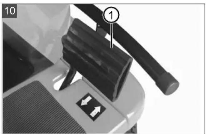


R85.1 Li

127617

(2000 x 848 x 1040) mm

ca. 173 kg
800 W (max. 1300 W)

Modes: F, N, R

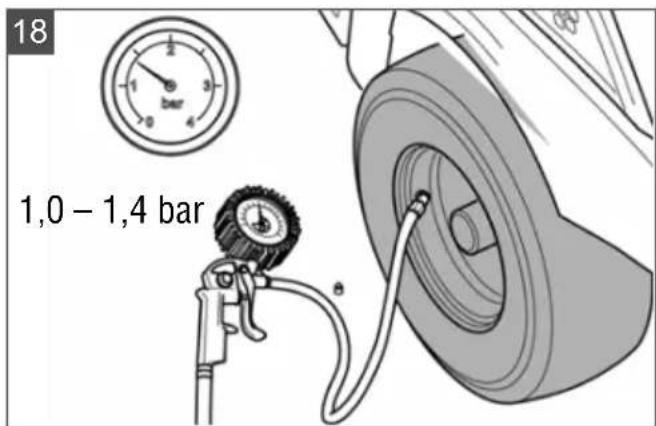
1,0 - 1,4 bar
max. 6 km/h
max. 5 km/h

81 cm
1: 25 mm, 2: 31 mm, 3: 39 mm, 4: 49 mm, 5: 61 mm,
6: 73 mm, 7: 86 mm, 8: 100 mm, 9: 113 mm, 10: 127 mm
ca. 150 l
2800 min ^-1

2 x 800 W
Front: 81EF13020/32F
Rear: 81EF13021/32R


R85.1 Li
0^ C - 35^ C
LpA = 80,1 dB(A), K = 3 dB(A)
Measured: LwA = 93,81 dB(A), K = 3 dB(A)
Guaranteed: LwA = 97 dB(A)
Left: 2,18 m/s ^2 , K = 1,5 m/s ^2
Right: 2,01 m/s ^2 , K = 1,5 m/s ^2
1,16 m/s ^2 , K = 1,5 m/s ^2


Lithium-Polymer
72 V
31 Ah
2200 Wh

Charger
100 - 240 V AC, 50/60 Hz
2,5 A, 250 VA
84 V / 2,5 A
12 h
(first time: 12 - 15 h)

0 - 40^
natural_image
Simple line drawing of a microphone with a curved cord (no text or symbols)Ladebuchse

Taster RMO, LED, CCS (04)
Pos. Beschreibung
www.al-ko.com/service-contacts
14 GARANTIE
1 General electrical machine safety warnings 32
1.1 Work area safety 32
1.2 Electrical safety 32
1.3 Personal safety 32
1.4 Electrical machine use and care ...... 33
1.5 Battery machine use and care 33
1.6 Service 33
2 About these instructions for use .... 34
2.1 Symbols on the title page.... 34
2.2 Legends and signal words ...... 34
3 Product description 34
3.1 Designated use 34
3.2 Possible foreseeable misuse .... 34
3.3 Residual risks.... 34
3.4 Safety and protective devices ...... 35
3.5 Symbols on the appliance 35
3.5.1 Safety signs 35
3.5.2 Operating signs 36
3.6 Scope of supply.... 36
3.7 Product overview (01) 37
3.8 Controls (02 - 12) ...... 37
4 Safety instructions 38
4.1 Safety instructions for ride-on mow-ers 38
4.2 Safety information regarding the rechargeable battery 40
4.3 Safety information regarding the charging unit.... 40
5 Start-up 40
5.1 Unpacking the ride-on mower (13, 14) 40
5.2 Removing the mulch insert (15) ...... 41
5.3 Hooking in and removing the grass catcher (16, 17) .... 41
5.4 Checking the tyre pressure (18)...... 41
5.5 Charging the rechargeable bat- tery (19 – 21)...... 41
5.6 Checking the safety and protective devices 41
5.6.1 Checking the mower mechanism contact switch 42
5.6.2 Checking the seat contact switch. 42
5.6.3 Checking the grass catcher contact switch 42
5.6.4 Carrying out a visual inspection of the mower deck.... 42
6 Operation.... 42
6.1 Adjusting the operator's seat (22)...... 42
6.2 Inserting the mulch insert (23, 24) ..... 42
6.3 Activating/deactivating the parking brake.... 42
6.4 Starting and stopping the ride-on mower.... 42
6.5 Switching the mower mechanism on and off.... 43
6.6 Setting the cutting height 43
6.7 Driving at constant speed 43
6.8 Mowing backwards 43
6.9 Emptying the grass catcher 43
6.10 Switching the headlights on and off.... 44
7 Working behaviour and working technique.... 44
7.1 Mowing interval.... 44
7.2 Mowing high grass.... 44
7.3 Mulching 44
8 Maintenance and care.... 44
8.1 Maintenance schedule.... 44
8.2 Cleaning the ride-on mower 44
8.2.1 Removing and emptying the grass catcher 45
8.2.2 Cleaning the housing and operating elements.... 45
8.2.3 Cleaning the discharge channel... 45
8.2.4 Cleaning the mower deck 45
8.3 Maintaining the cutting blades 45
9 Help in case of malfunction...... 45
9.1 Malfunction table 45
9.2 Carrying out a self-test 48
10 Transport 48
11 Storage 48
12 Disposal 48
12.1 Removing the rechargeable battery ... 48
12.2 Legal notes.... 48
13 After-Sales / Service 49
14 Guarantee.... 50
1 GENERAL ELECTRICAL MACHINE SAFETY WARNINGS
WARNING! Read all safety warnings, instructions, illustrations and specifications provided with this machine. Failure to follow all instructions listed below may result in electric shock, fire and/or serious injury.
■ Save all warnings and instructions for future reference.
The term "machine" in the warnings refers to your mains-operated (corded) machine or battery-operated (cordless) machine.
1.1 Work area safety
- Keep work area clean and well lit. Cluttered or dark areas invite accidents.
- Do not operate machines in explosive atmospheres, such as in the presence of flammable liquids, gases or dust. Machines create sparks which may ignite the dust or fumes.
- Keep children and bystanders away while operating a machine. Distractions can cause you to lose control.
1.2 Electrical safety
■ Machine plugs must match the outlet. Never modify the plug in any way. Do not use any adapter plugs with earthed (grounded) machines. Unmodified plugs and matching outlets will reduce risk of electric shock.
- Avoid body contact with earthed or grounded surfaces, such as pipes, radiators, ranges and refrigerators. There is an increased risk of electric shock if your body is earthed or grounded.
- Do not expose machines to rain or wet conditions. Water entering a machine will increase the risk of electric shock.
- Do not abuse the cord. Never use the cord for carrying, pulling or unplugging the machine. Keep cord away from heat, oil, sharp edges or moving parts. Damaged or entangled cords increase the risk of electric shock.
- When operating a machine outdoors, use an extension cord suitable for outdoor use. Use of a cord suitable for outdoor use reduces the risk of electric shock.
If operating a machine in a damp location is unavoidable, use a residual current device (RCD) protected supply. Use of an RCD reduces the risk of electric shock.
1.3 Personal safety
■ Stay alert, watch what you are doing and use common sense when operating a machine. Do not use a machine while you are tired or under the influence of drugs, alcohol or medication. A moment of inattention while operating machines may result in serious personal injury.
■ Use personal protective equipment. Always wear eye protection. Protective equipment such as dust mask, non-skid safety shoes, hard hat or hearing protection used for appropriate conditions will reduce personal injuries.
■ Prevent unintentional starting. Ensure the switch is in the off-position before connecting to power source and/or battery pack, picking up or carrying the machine. Carrying machines with your finger on the switch or energising machines that have the switch on invites accidents.
■ Remove any adjusting key or wrench before turning the machine on. A wrench or a key left attached to a rotating part of the machine may result in personal injury.
- Do not overreach. Keep proper footing and balance at all times. This enables better control of the machine in unexpected situations.
■ Dress properly. Do not wear loose clothing or jewellery. Keep your hair and clothing away from moving parts. Loose clothes, jewellery or long hair can be caught in moving parts.
If devices are provided for the connection of dust extraction and collection facilities, ensure these are connected and properly used. Use of dust collection can reduce dust-related hazards.
- Do not let familiarity gained from frequent use of machines allow you to become complacent and ignore machine safety principles. A careless action can cause severe injury within a fraction of a second.
1.4 Electrical machine use and care
- Do not force the machine. Use the correct machine for your application. The correct machine will do the job better and safer at the rate for which it was designed.
- Do not use the machine if the switch does not turn it on and off. Any machine that cannot be controlled with the switch is dangerous and must be repaired.
■ Disconnect the plug from the power source and/or remove the battery pack, if detachable, from the machine before making any adjustments, changing accessories, or storing machines. Such preventive safety measures reduce the risk of starting the machine accidentally.
■ Store idle machines out of the reach of children and do not allow persons unfamiliar with the machine or these instructions to operate the machine. Machines are dangerous in the hands of untrained users. - Maintain machines and accessories. Check for misalignment or binding of moving parts, breakage of parts and any other condition that may affect the machine's operation. If damaged, have the machine repaired before use. Many accidents are caused by poorly maintained machines.
- Keep cutting tools sharp and clean. Properly maintained cutting tools with sharp cutting edges are less likely to bind and are easier to control.
Use the machine, accessories and tool bits etc. in accordance with these instructions, taking into account the working conditions and the work to be performed. Use of the machine for operations different from those intended could result in a hazardous situation. - Keep handles and grasping surfaces dry, clean and free from oil and grease. Slip-
pery handles and grasping surfaces do not allow for safe handling and control of the machine in unexpected situations.
1.5 Battery machine use and care
■ Recharge only with the charger specified by the manufacturer. A charger that is suitable for one type of battery pack may create a risk of fire when used with another battery pack.
■ Use machines only with specifically designated battery packs. Use of any other battery packs may create a risk of injury and fire.
- When battery pack is not in use, keep it away from other metal objects, like paper clips, coins, keys, nails, screws or other small metal objects, that can make a connection from one terminal to another. Shorting the battery terminals together may cause burns or a fire.
■ Under abusive conditions, liquid may be ejected from the battery; avoid contact. If contact accidentally occurs, flush with water. If liquid contacts eyes, additionally seek medical help. Liquid ejected from the battery may cause irritation or burns.
- Do not use a battery pack or tool that is damaged or modified. Damaged or modified batteries may exhibit unpredictable behaviour resulting in fire, explosion or risk of injury.
- Do not expose a battery pack or tool to fire or excessive temperature. Exposure to fire or temperature above 130 °C may cause explosion.
■ Follow all charging instructions and do not charge the battery pack or machine outside the temperature range specified in the instructions. Charging improperly or at temperatures outside the specified range may damage the battery and increase the risk of fire.
1.6 Service
■ Have your machine serviced by a qualified repair person using only identical replacement parts. This will ensure that the safety of the machine is maintained.
■ Never service damaged battery packs.
Service of battery packs should only be performed by the manufacturer or authorized service providers.
2 ABOUT THESE INSTRUCTIONS FOR USE
The German version is the original operating instructions. All additional language versions are translations of the original operating instructions.
■ Always safeguard these operating instructions so that they can be consulted if you need any information about the appliance.
■ Only pass on the appliance to other persons together with these operating instructions.
■ Comply with the safety and warning information in these operating instructions.
The ride-on mowers are supplied with different levels of equipment. Please note that the figures may differ from the original. Please contact a specialist workshop or the manufacturer if you encounter difficulties in following the descriptions.
2.1 Symbols on the title page
Symbol Meaning

It is essential to read through these operating instructions carefully before start-up. This is essential for safe working and trouble-free handling.

Operating instructions

Handle Li-Ion rechargeable batteries with care! In particular, observe the notes on transport, storage and disposal in these operating instructions!
2.2 Legends and signal words
⚠️ DANGER! Denotes an imminently dangerous situation which will result in fatal or serious injury if not avoided.
WARNING! Denotes a potentially dangerous situation which can result in fatal or serious injury if not avoided.
CAUTION! Denotes a potentially dangerous situation which can result in minor or moderate injury if not avoided.
IMPORTANT! Denotes a situation which can result in material damage if not avoided.
NOTE Special instructions for ease of understanding and handling.
3 PRODUCT DESCRIPTION
3.1 Designated use
The ride-on mower is intended for mowing in domestic gardens and allotments with a max. slope of 12^ (21 %). Additional applications, such as for mulching, are only permitted if the original accessories are used and in compliance with the maximum load values.
This trailer is intended solely for use in non-commercial applications. Any other use (as well as unauthorised conversions or add-ons) are regarded as contrary to the intended use and will result in exclusion of the warranty as well as loss of conformity (CE mark); the manufacturer will thus decline any responsibility for damage and/or injury suffered by the user or third parties.
3.2 Possible foreseeable misuse
The ride-on mower is not designed for commercial use in public parks, sports grounds, agriculture and forestry.

WARNING! Dangers due to overloading
the ride-on mower! Make sure that the permissible inclines/declines are not exceeded. Exceeding these values may exceed the braking capacity of the ride-on mower and lead to dangerous situations!

NOTE Bear in mind that the ride-on mower is not have approval for road use, and thus is allowed to be driven on public roads!
3.3 Residual risks
Even during correct use of the appliance, there is always a certain residual risk that cannot be excluded. Depending on the use, the following potential risks can be derived from the type and construction of the appliance:
- Throwing out of cuttings, soil and small stones.
■ Inhalation of cuttings particles if no breathing protection is worn.
■ Lacerations from reaching into the rotating cutting blade.
3.4 Safety and protective devices
WARNING! Danger if protective devices are removed or manipulated! Do not operate with any protective devices removed or manipulated. Defective protective devices must be repaired or renewed immediately!
The safety and protective devices mentioned here are components of the safety concept to prevent risks to the user. Due to this safety concept, the ride-on mower can only be switched on by turning the safety key under the following conditions:
■ The drive motor is off.
■ The mower mechanism is switched off.
■ The user is sitting in the operator's seat.
■ The driving mode switch is set to N (Neutral).
Key-operated rotary switch
The ride-on mower can only be switched on when the safety key is inserted into the key-operated rotary switch and turned to green (ON position) (see chapter 3.8 "Controls (02 – 12)", page 37).
Mower mechanism contact switch
The mower mechanism contact switch ensures that the ride-on mower can only be switched on when the mower mechanism is switched off (see chapter 5.6.1 "Checking the mower mechanism contact switch", page 42).
Seat contact switch
The seat contact switch ensures that the ride-on mower cannot be switched on and that the engines for the travel drive and mower mechanism are switched off as soon as there is no-one in the operator's seat (see chapter 5.6.2 "Checking the seat contact switch", page 42).
This safety concept is extended for the mower mechanism engines by the behaviour described in the following "Grass catcher contact switch" section.
Grass catcher contact switch
The contact switch of the grass catcher ensures that:
The mower mechanism engines cannot be switched on if the grass catcher is not correctly attached.
The mower mechanism engines switch off as soon as the grass catcher is not correctly hooked in when the mower mechanism is switched on.
Checking the contact switch: see chapter 5.6.3 "Checking the grass catcher contact switch", page 42.
Mower deck housing
The mower deck housing prevents contact with the cutting blades and objects such as stones being thrown out (see chapter 5.6.4 "Carrying out a visual inspection of the mower deck", page 42).
3.5 Symbols on the appliance
3.5.1 Safety signs
Symbol Meaning

General warning signs. Pay special attention when handling this product.

Risk of injury due to objects being thrown out!
Keep other people, especially children and animals, out of the working area during mowing.

Read the operating instructions before starting operation.

Wait until the mower mechanism stops before touching it. The mower mechanism continues to run after being switched off and can cause serious injuries.
Danger of electric shock from contact with live parts! Keep flexible power lines away from the mower mechanism and other moving machine parts.

Keep your hands and feet away from the blade system.
Symbol Meaning
Before maintenance and repair work, switch off the appliance and remove the safety key.

Do not use the appliance in the rain or on wet grass. Do not store the appliance in the open air.

Do not spray the equipment with water.
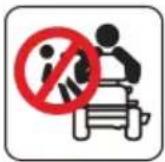
Do not carry any passengers.
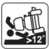
Do not drive on gradients of more than 12^ (21 %).

Do not spray the ride-on lawn-mower and mower mechanism with a garden hose or high-pressure cleaner.

Wear safety goggles and ear protectors.
Symbol Meaning
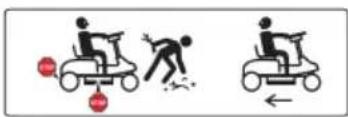
Stop the appliance immediately if another person is in the vicinity.
Pay special attention when reversing.
Symbol Meaning
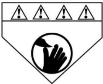
Keep your hands and feet away from the mower mechanism.
3.5.2 Operating signs
Symbol Meaning
Danger of collision when mowing in reverse! Pay particular attention to the rear surroundings.
Align the grass catcher exactly when hooking it in.

Drive pedal

Brake pedal

Locking lever for brake pedal
natural_image
Simple line drawing of a microphone with a curved cord (no text or symbols)Charging socket

Screw the charging plug tight in a clockwise direction after plugging in.
3.6 Scope of supply
The items listed here are included as standard. Check that all items are present:
- Ride-on mower with grass catcher
■ Mulch insert in ride-on mower
■ Battery charger with charging cable and 2 mains cables (EU, UK)
- Operating instructions
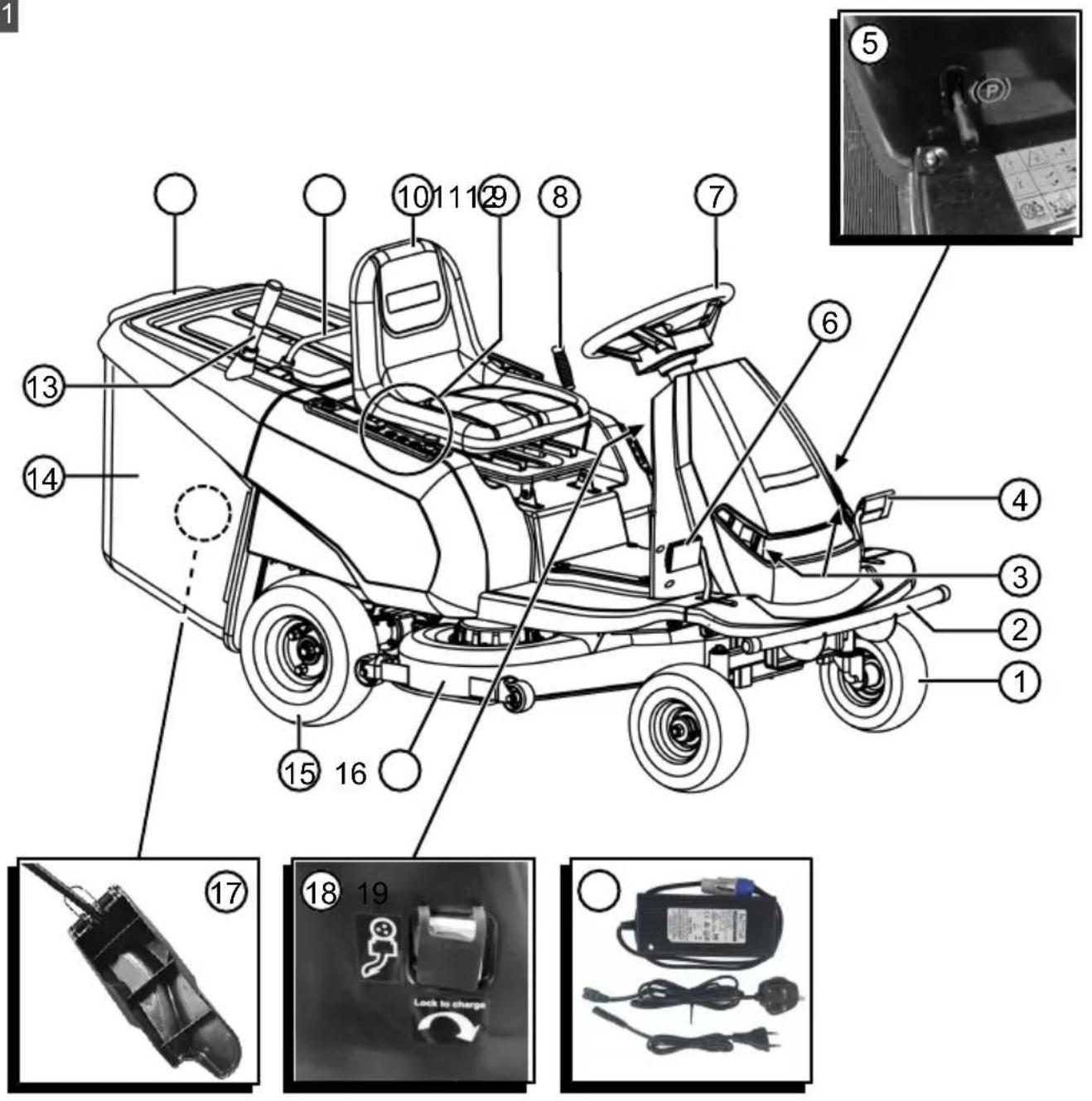
3.7 Product overview (01)
Item Component
| 1 Front wheels, steered |
| 2 Bumper |
| 3 Headlights |
| 4 Brake pedal |
| 5 Locking lever for brake pedal |
| 6 Drive pedal |
| 7 Steering wheel |
| 8 Adjusting lever for cutting height |
| 9 Control panel |
| 10 Operator's seat |
| 11 Front carry handle of the grass catcher |
| 12 Rear carry handle of the grass catcher |
| 13 Telescopic lever of the grass catcher |
| 14 Grass catcher |
| 15 Rear wheels, driven |
| 16 Mower deck |
| 17 Mulch insert |
| 18 Charging socket |
| 19 Battery charger with charging cable and 2 mains cables (EU, UK) |
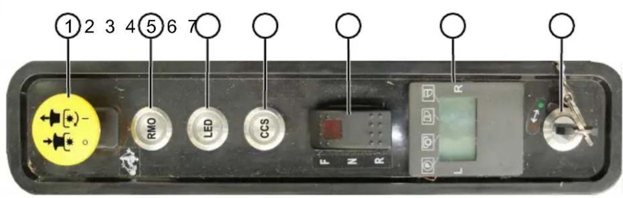
3.8 Controls (02 - 12)
Control panel (02)
Item Control
| 1 Push/pull switch for mower mechanism |
| 2 RMO button (see below) |
| 3 LED button (see below) |
| 4 CCS button (see below) |
| 5 Drive mode switch |
| 6 Central status display |
| 7 Key switch |
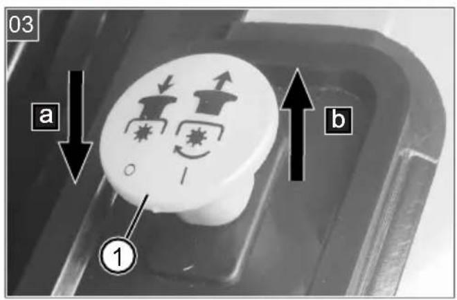
Push/pull switch for mower mechanism (03)
Item Description
| 1 Push/pull switch for mower mechanism |
| a Pushing the switch downwards: Switch off mower mechanism. |
| b Pulling the switch upwards: Switch on the mower mechanism. |
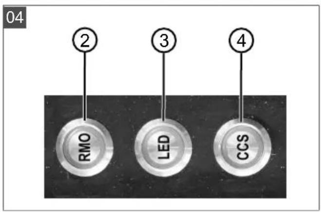
RMO, LED, CCS buttons (04)
Item Description
| 2 RMO: Switch reverse mowing on/off (RMO: Reverse Mowing Mode). |
| 3 LED: Switch headlights on/off (LED: Light Emitting Diode). |
| 4 CCS: Switch on constant speed (CCS: Cruise Control System). |
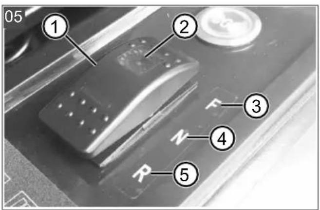
Drive mode switch (05)
Item Description
| 1 Drive mode switch |
| 2 LED: Lights up when drive mode F is switched on. |
| 3 Drive mode F: Drive forwards (F: Forward). |
| 4 Drive mode N: Ride-on mower is stationary (N: Neutral). |
| 5 Drive mode R: Drive in reverse (R: Reverse). |
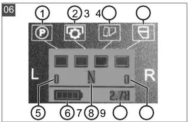
Central status display (06)
When the ride-on mower is ready to drive, all four operating status displays (06/1) to 06/4) light up.
Item Display Lights up Does not
| light up | |||
| 1 Locking lever for brake pedal | Brake pedal released | Brake pedal applied | |
| 2 Mower mechanism | Mower mechanism is switched off | Mower mechanism is switched on | |
| 3 Grass catcher | Box closed | Box tilted or not properly hooked in. | |
Item Display Lights up Does not
light up
| 4 Fill-level indicator | Box empty Box full |
Item Display
| 5 Left mower mechanism engine speed in [rpm] |
| 6 Charge status display for the recharge-able battery |
| 7 F, N or R drive mode (see above) |
| 8 Total operating time of the ride-on mow-er in [h] |
| 9 Right mower mechanism engine speed in [rpm] |
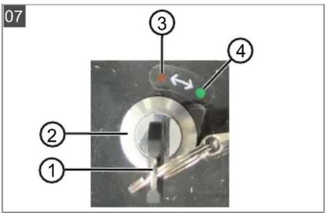
Key-operated rotary switch (07)
| Item Description |
| 1 Safety key |
| 2 Key-operated rotary switch |
| 3 Red (OFF position): Power switched off. |
| 4 Green (ON position): Power switched on. |
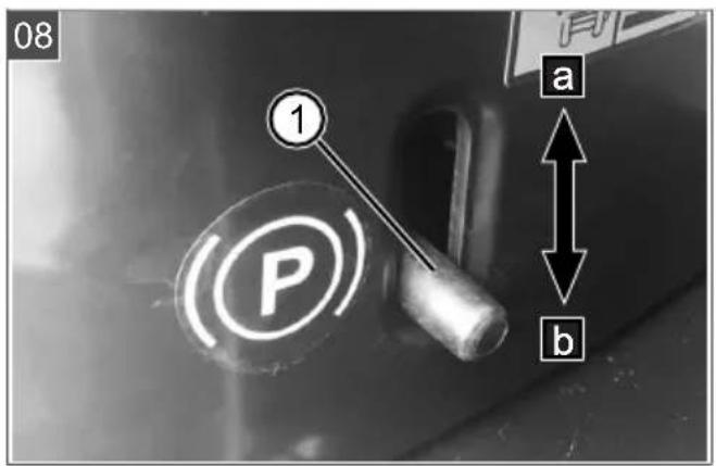
Locking lever for brake pedal (08)
| Item Description |
| 1 Locking lever for brake pedal |
| a Pushing upwards: Brake pedal applied, i.e. the ride-on mower is stationary. |
| b Pushing downwards: Brake pedal released. |
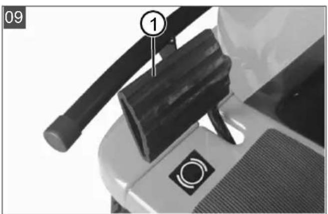
Brake pedal (09)
| Item Description |
| 1 Brake pedal, on the left of the ride-on lawn mower |
Drive pedal (10)
| Item Description |
| 1 Drive pedal, on the right of the ride-on lawnmower |
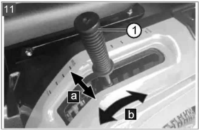
Adjusting lever for cutting height (11)
| Item Description |
| 1 Adjusting lever for cutting height |
| a Move the lever to the side to engage and disengage. |
| b Push the lever for adjusting the cutting height up or down (10 steps). |
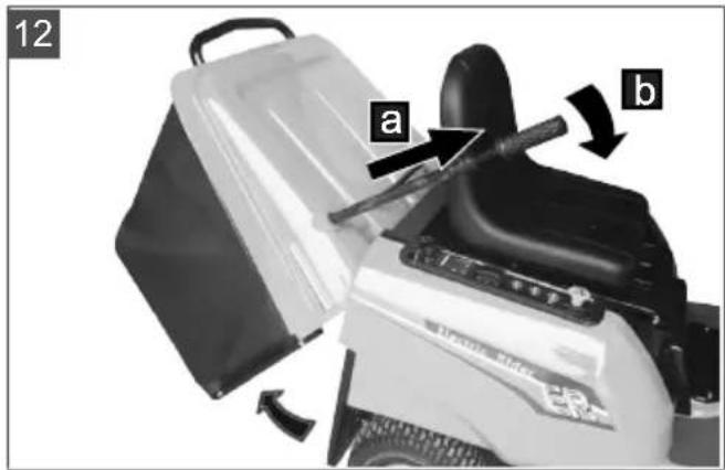
Telescopic lever of the grass catcher (12)
| Item Description |
| 1 Telescopic lever of the grass catcher |
| a Pull out the lever. |
| b Push the lever forwards for emptying. |
4 SAFETY INSTRUCTIONS
4.1 Safety instructions for ride-on mowers
Training
- Read the operating instructions carefully. Familiarise yourself with the control devices and the correct use of the appliance.
■ Never allow children or other persons who are not familiar with the operating instructions to use the lawnmower.
Children and teenagers should be supervised so that they do not play with the appliance.
- Cleaning and maintenance must not be carried out by children.
- Local regulations may specify the minimum age of the user.
■ Never mow when there is anyone, especially children or animals, in the vicinity. Keep other people out of the danger area.
Remember that you, as the user, are responsible for accidents involving other people or their property.
Preparatory measures
■ Always wear sturdy shoes and long trousers when operating the appliance. Do not operate the appliance when barefoot or wearing light sandals. Avoid wearing loose clothing or clothing with dangling cords or belts.
- Check the area where the appliance is being used and remove any objects that could be picked up and thrown out by the appliance (e.g. stones, toys, sticks, wires).
Before using the appliance, always check if the cutting blades, fastening bolts and the entire mowing unit are worn or damaged. Worn or damaged cutting blades and fastening bolts must only be replaced as a set to avoid unbalance. Worn or damaged information signs must be replaced.
Handling
- Do not mow, or mow with particular care, in difficult terrain where the ride-on mower could tip over, such as slopes, near drop-offs, ditches or embankments, along dykes and nearby landfill sites.
- Do not mow on slopes with an inclination that exceeds the slope specified in the technical data. Never drive transversely to the slope.
■ Be especially careful when changing the direction of travel on a slope.
■ Comply with the permitted operating times in your vicinity.
■ Only mow during daylight hours or with good artificial lighting.
- Do not work with the appliance in bad weather conditions, especially when it is raining or when thunderstorms are approaching. No protection against lightning strikes.
■ Never use the appliance with damaged protective devices or protective grilles or without mounted protective devices, e.g. baffle plates and/or grass catcher. Damaged protective devices and covers must be replaced, missing protective devices and covers must be correctly fitted.
■ Never put your hands or feet on or under rotating parts.
- Do not carry any passengers on the machine.
If possible, avoid using the appliance on wet grass. Wet grass clumps together and can clog the mower mechanism and the discharge channel.
■ Switch off the mower mechanism and raise it to its maximum position to prevent damage when driving over areas that are not to be mowed and which are stony or uneven.
■ Before leaving and parking the ride-on mower, activate the parking brake to prevent it from rolling away.
■ Switch off the ride-on mower and remove the safety key. Make sure that all moving parts have come to a complete stop:
■ when leaving the ride-on lawnmower,
■ before removing blockages or clogging in the discharge channel,
■ before inspecting, cleaning or working on the ride-on mower,
■ after encountering a foreign object. Check for damage to the ride-on mower and carry out the necessary repairs before restarting and working with the ride-on mower.
If the ride-on mower starts to vibrate in an unusual way, an immediate check is required:
Check for damage.
- Carry out the necessary repairs of damaged parts.
■ Make sure that all nuts, bolts and screws are firmly tightened.
Maintenance, storage and transport
■ Repairs on the machine must be carried out by the manufacturer or by one of its customer service centres.
■ Make sure that all nuts, bolts and screws are tightened and the appliance is in a safe working condition.
■ Regularly check the grass catcher for wear or loss of functional capability.
- Replace worn or damaged parts due to safety reasons.
- On appliances fitted with several cutting blades, note that the movement of one cutting blade can cause the other cutting blades to rotate.
■ When maintaining the cutting blades, be aware that the cutting blades can be moved even when the power supply is switched off.
- Replace worn or damaged parts due to safety reasons. Only use original spare parts and accessories.
The ride-on mower does not have approval for road use and may not be driven on public roads.
This ride-on mower is not allowed to be towed. Use a suitable vehicle for transport on public roads.
The ride-on mower can cause serious injuries due to its dead weight. Take particular care when loading and unloading the ride-on mower to transport it on a vehicle or trailer.
4.2 Safety information regarding the rechargeable battery
This section mentions all the basic safety instructions to be heeded when using the rechargeable battery. Read these instructions.
■ Fully charge the rechargeable battery before using it for the first time and always use the specified charger. Comply with the details given in these instructions for use for charging the rechargeable battery.
- Do not use the rechargeable battery in environments where there is a potential risk of explosion and/or fire.
- Do not expose the rechargeable battery to moisture and humidity when in use with the appliance.
■ Protect the rechargeable battery from heat, oil and fire to prevent it being damaged so no vapours and electrolyte liquids can escape. There is a danger of explosion!
- Do not open, dismantle or crush the rechargeable battery. There is a danger of electric shock and short-circuit.
An improperly used and damaged rechargeable battery can cause vapours and electrolyte liquid to escape. Vent the room adequately and in the case of any disorders, consult a doctor.
If accidental contact with electrolyte liquid occurs, flush with water and thoroughly rinse the eyes immediately. Then consult a doctor.
4.3 Safety information regarding the charging unit
This section mentions all the basic safety and warning information to be heeded when using the charging unit. Read these instructions.
■ Only use the charging unit as designated, i.e. for charging the intended rechargeable batteries. Only charge original rechargeable batteries from AL-KO in the charging unit.
Before each use, inspect the entire charging unit – and especially the mains cable – for damage. Only use the charging unit when it is in proper working order.
- Do not use the charging unit in environments where there is a potential risk of explosion and/or fire.
■ Only operate the charging unit indoors and do not expose it to moisture and humidity.
- Do not cover the charging unit during the charging process.
Before connecting the charging unit, make sure that the mains voltage matches the voltage stated in the "Technical data".
■ Only use the mains cable for connecting the charging unit, not for any other purpose. Do not carry the charging unit by the mains cable and do not remove the power plug from the power outlet by pulling on the mains cable.
■ Protect the mains cable from heat, oil and sharp edges to prevent it being damaged.
- Do not open the charging unit. There is a danger of electric shock and short-circuit.
For your own safety, only have the charging unit repaired by qualified specialist personnel using genuine spare parts.
Dry the unused charging unit and store in a closed place. Unauthorised persons and children must not have access to the charging unit.
5 START-UP
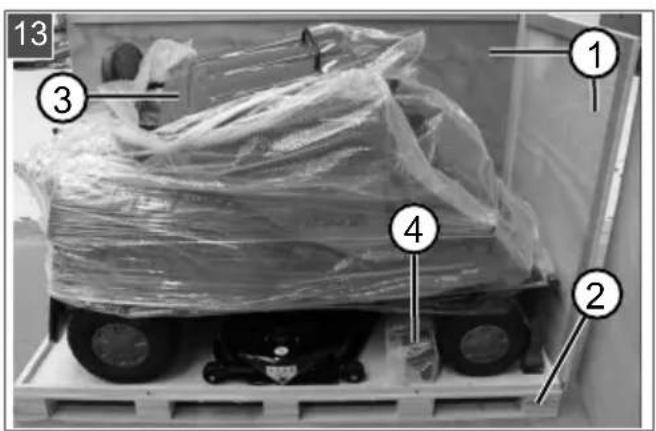
5.1 Unpacking the ride-on mower (13, 14)
The ride-on mower is delivered packed in a wooden crate. For unpacking, choose firm and level ground with sufficient space for handling the ride-on mower and packaging. Use the appropriate tool for all work.

WARNING! Risk of personal injury and
damage to the mower mechanism! Improper unloading of the ride-on mower from the wooden pallet can cause injury to persons and damage to the mower mechanism of the ride-on mower.
- Unload the ride-on mower as described in the following steps.
- Carefully remove the cover and side walls (13/1) from the pallet base (13/2).
- Remove the packaging foil.
- Lift out the grass catcher (13/3).
- Remove the accessory parts (13/4).
- Remove the packaging foils.
- Check the scope of supply (see chapter 3.6 "Scope of supply", page 36).
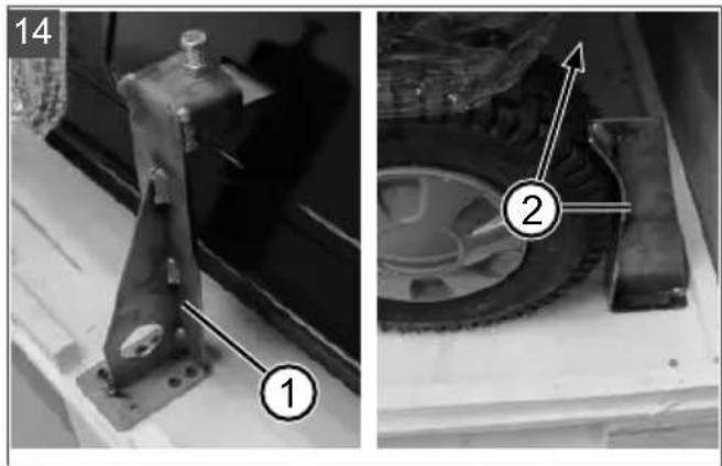
- Remove the rear transport safety lock (14/1) and the front transport locks (14/2).
- Place a loading ramp of suitable width with a non-slip surface and sufficient strength close to the pallet floor.
-
Set the mower deck to the uppermost position (see chapter 6.6 "Setting the cutting height", page 43).
-
Deactivate the parking brake (see chapter 6.3 "Activating/deactivating the parking brake", page 42).
- Carefully roll the ride-on mower – at least two persons – off the pallet base down the loading ramp.
- Activate the parking brake (see chapter 6.3 "Activating/deactivating the parking brake", page 42).
5.2 Removing the mulch insert (15)
The mulch insert has been inserted into the ride-on mower for transport. In order to operate the ride-on mower with the grass catcher, it must be removed.
- Unhook the springs (15/1) and (15/2).
- Pull the mulch insert out of the discharge chute (15/a) by the handle (15/3).
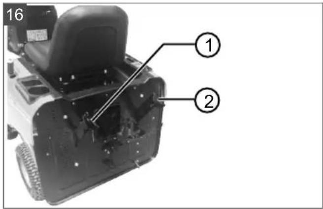
5.3 Hooking in and removing the grass catcher (16, 17)
Hooking in the grass catcher
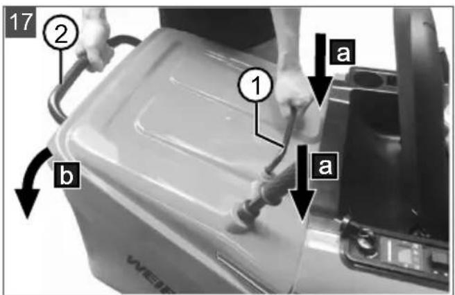
- Hook the grass catcher into the two hooks (16/1, 16/2) on the ride-on mower in a tilted position (17/a). Hold the grass catcher by the front carry handle (17/1) and the rear carry handle (17/2).
Note: The grass catcher must be hung in symmetrically.
- Tilt the grass catcher downwards (17/b) until it lies on the ride-on mower and engages.
- Check the grass catcher is correctly seated.
Remove the grass catcher
The grass catcher is removed in the reverse sequence.
5.4 Checking the tyre pressure (18)
The correct tyre pressure is an important prerequisite for a correctly levelled mower mechanism, and hence for a uniformly mown lawn.
- Check the tyre pressure at regular intervals (see technical data).
- If the tyre pressure is too low: Inflate the tyres using a standard foot pump.
NOTE 1 PSI = 0.07 bar.
5.5 Charging the rechargeable battery (19 - 21)
i NOTE Fully charge the rechargeable battery before using it for the first time. The rechargeable battery can be charged in any charge state.
When charging the rechargeable battery for the first time, charge it continuously for 12 to 15 hours to reach full capacity. The ambient temperature must be between 0 and 40 °C.
The charge status display (06/6) for the battery can be found on the central status display (06).
IMPORTANT! Danger of short circuit! A short-circuit in an open charging plug can lead to a fire.
■ Please follow the procedure described here to start and stop the charging process.
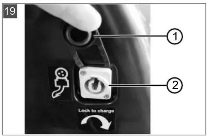
Starting the charging process
- Drive the ride-on mower close to the mains socket and stop.
- Turn the safety key to red (OFF position).
- Open the cover (19/1) of the charging socket (19/2).
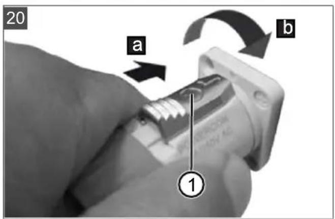
- Insert the charge plug into the charging socket (20/a) with the release button (20/1) facing upwards.
- Screw tight the charge plug clockwise (20/b).
- Insert the mains plug of the charger into the power socket. The charging process begins.
LED on the charger
■ LED lights red: Rechargeable battery is not yet fully charged.
■ LED lights green: The rechargeable battery is fully charged.
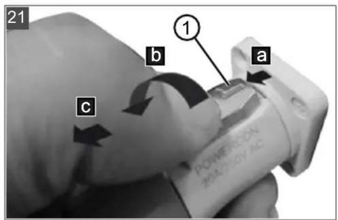
Completing the charging process
- Remove the mains plug of the charger from the power socket.
- Push back the release button (21/1) at the charging plug (21/a).
- Turn the charging plug anticlockwise (21/b) and pull it out (21/c).
5.6 Checking the safety and protective devices
Check the safety and protective devices each time before the ride-on mower is started. Perform all checks on a level surface so that the ride-on mower cannot roll away unintentionally.
WARNING! Danger when checking the safety devices! The safety devices may only be checked from the operator's seat and when no other persons or animals are in the vicinity!
Function of the safety and protective devices: see chapter 3.4 "Safety and protective devices", page 35.
5.6.1 Checking the mower mechanism contact switch
Requirements: The drive engine is off and the parking brake is applied.
- Sit on the operator's seat.
- Pull the push/pull switch (03/1) upwards to switch on the mower mechanism.
- Set the driving mode switch (05/1) to N.
- Turn the safety key (07/1) to green (ON position).
NOTE The engines for the travel drive and for the mower mechanism must not start.
5.6.2 Checking the seat contact switch
Requirements: The drive engine is off and the parking brake is applied.
- Sit on the operator's seat.
- Press push/pull switch (03/1) downwards to switch off the mower mechanism.
- Set the driving mode switch (05/1) to N.
- Turn the safety key (07/1) to green (ON position).
- To deactivate the parking brake, press the brake pedal (09/1) and release it again.
- Pull the push/pull switch (03/1) upwards to switch on the mower mechanism.
- Remove the load on the seat by standing up briefly, but do not dismount.
NOTE The engines for the travel drive and for the mower mechanism must switch off.
5.6.3 Checking the grass catcher contact switch
Requirements: The drive engine is off and the parking brake is applied.
- Sit on the operator's seat.
- Press push/pull switch (03/1) downwards to switch off the mower mechanism.
- Set the driving mode switch (05/1) to N.
- Turn the safety key (07/1) to green (ON position).
- To deactivate the parking brake, press the brake pedal (09/1) and release it again.
- Pull the push/pull switch (03/1) upwards to switch on the mower mechanism.
- Lift the empty grass catcher slightly.
NOTE The engines for the mower mechanism must switch off.
5.6.4 Carrying out a visual inspection of the mower deck
Check that the mower deck housing is undamaged and does not allow access to the cutting blades. If damaged, contact a customer service workshop.
6 OPERATION
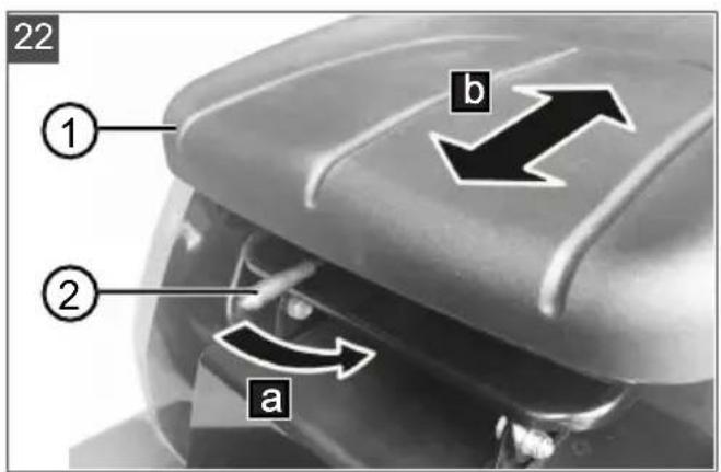
6.1 Adjusting the operator's seat (22)
To improve seating comfort, the operator's seat (22/1) can be moved forwards or backwards.
- Press the unlocking lever (22/2) to the left (22/a).
- Move the operator's seat forwards or backwards (22/b).
- Release the unlocking lever to lock in the new position.
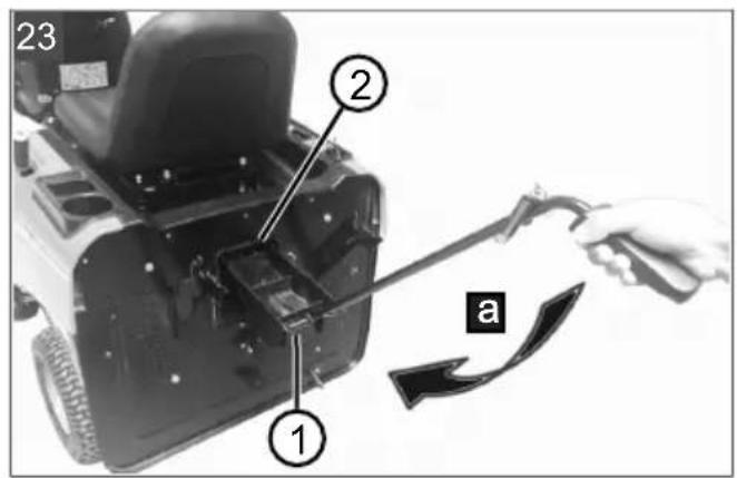
6.2 Inserting the mulch insert (23, 24)
- Remove the grass catcher (see chapter 5.3 "Hooking in and removing the grass catcher (16, 17)", page 41).
- Push the mulch insert (23/1) into the discharge chute (23/2) as far as it will go (23/a).
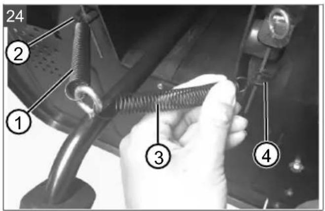
- Attach the spring (24/1) to the left hook (24/2).
- Attach the spring (24/3) to the right hook (24/4).
- Hook in the grass catcher again.
6.3 Activating/deactivating the parking brake
Activating the parking brake
- Push the brake pedal (09/1) as far as it will go and hold it there.
- Press the locking lever (08/1) upwards.
- Release the brake pedal.
Deactivating the parking brake
- Press the brake pedal (09/1).
6.4 Starting and stopping the ride-on mower
Starting the ride-on mower
- Sit on the operator's seat.
- Press push/pull switch (03/1) downwards to switch off the mower mechanism.
- Set the driving mode switch (05/1) to N (Neutral).
-
Turn the safety key (07/1) to green (ON position).
-
Set the driving mode switch (05/1) to F (Forward) or R (Reverse).
- Slowly press the driving pedal (10/1) down until the desired driving speed is reached.
Stopping the ride-on mower
- Press down the brake pedal (09/1) until the mower comes to a standstill and hold it there.
- Set the driving mode switch (05/1) to N (Neutral).
- Press the locking lever (08/1) upwards to activate the parking brake.
- Release the brake pedal.
- Turn the safety key (07/1) to red (OFF position).
- Now you can get off the operator's seat.
6.5 Switching the mower mechanism on and off
Requirements: The ride-on mower has been started and the driving mode switch (05/1) is set to N (Neutral) or F (Forward).
Switching on the mower mechanism
- Pull the push/pull switch (03/1) upwards.
Switch off mower mechanism
- Push the push/pull switch (03/1) downwards.
6.6 Setting the cutting height
- Pull the cutting height adjustment lever (11/1) towards the operator's seat to disengage it.
- Move the adjustment lever to adjust the cutting height in steps (for the cutting heights, see technical data):
■ Downwards: for low cutting height.
■ Upwards: for high cutting height.
- Push the adjusting lever outwards to engage.
i NOTE Always lock the lever in the selected position so that the mower mechanism is fixed and does not move unexpectedly.
6.7 Driving at constant speed
Switching on constant speed
- Press the driving pedal (10/1) down until the desired driving speed is reached.
- Press the CCS button (04/1).
- Take your foot off the drive pedal. The ride-on mower travels at a constant speed.
Switching off constant speed
■ Press the brake pedal (09/1). OR:
■ Press the drive pedal (10/1). OR:
■ Press the CCS button (04/1).
6.8 Mowing backwards
WARNING! There is an accident risk when reverse mowing! Risk of collision with persons and objects behind the ride-on mower. Serious injuries are possible.
■ Pay attention to the area behind you when mowing in reverse.
■ Only mow in reverse when it is necessary to do so.
Requirements: The ride-on mower has been started and the driving mode switch (05/1) is set to F (Forwards).
Switching on reverse mowing
- Pull the push/pull switch (03/1) upwards to switch on the mower mechanism.
- Set the cutting height (see chapter 6.6 "Setting the cutting height", page 43).
- Press the RMO button (04/2).
- Set the driving mode switch (05/1) to R (Reverse).
- Slowly press the driving pedal (10/1) down until the desired driving speed is reached. When doing so, keep a close eye on the surroundings at the rear.
Switching off reverse mowing
■ When you want to go forwards again: Set the driving mode switch to F (Forwards).
OR:
■ To continue reversing with the mower mechanism switched off: Push the push/pull switch (03/1) downwards.
6.9 Emptying the grass catcher
i NOTE An audible signal sounds when the grass catcher is full. The catcher should be emptied now if not before.
The ride-on mower is equipped with a manually operated grass catcher with telescopic lever.
■ The grass catcher can be emptied from the operator's seat.
If the grass catcher is folded up or unhinged when the mower mechanism is switched on,
the mower mechanism is automatically switched off.
■ The mower mechanism cannot be switched on unless the grass catcher is engaged correctly.
- Pull the telescopic lever (12/1) out of the grass catcher.
- Push the telescopic lever forwards to open the grass catcher. The cuttings fall out.
- Push the telescopic lever backwards until the grass catcher engages.
6.10 Switching the headlights on and off
- Press the LED button (04/3) to switch on.
- Press the LED button again to switch off.
7 WORKING BEHAVIOUR AND WORKING TECHNIQUE
7.1 Mowing interval
Please take into account that grass grows differently at different times. We recommend using a shorter interval between mowing during early spring. You can increase the mowing intervals as the growth rate of the grass begins to decline during the course of the year.
7.2 Mowing high grass
Mow with a higher cutting height adjustment when the grass is longer than normal or when it is wet. Then re-mow the grass with a lower, normal setting.
7.3 Mulching
For optimum mulching results, the grass should be mowed on a regular basis (approx. 1 or 2 times per week). Cut 1/3 of the grass height (e.g. if grass height is 6 cm, mow 2 cm). This will ensure that the mown grass will be properly intermixed in the remaining grass.
8 MAINTENANCE AND CARE
WARNING! Danger of cuts and lacerations. Danger of cuts and lacerations when reaching into sharp-edged, moving appliance parts and into cutting tools.
■ Before maintenance, care and cleaning work, always switch off the appliance. Remove the safety key.
■ Always wear protective gloves during maintenance, care and cleaning work.
8.1 Maintenance schedule
The following jobs are allowed to be carried out by the user independently. All other maintenance, service and repair work must be carried out in an authorised service workshop.
NOTE It may be necessary to shorten the maintenance intervals compared to those stated in the table above in case of severe loading and at high temperatures.
| Activity Before each | use | After each use | Each time be-fore putting in-to storage |
| Check the brake (test braking on a straight path). | X | ||
| Check the tyre pressure. X | |||
| Check the cutting blade. X | |||
| Check for loose parts. X | |||
| Clean the ride-on mower. X X |
8.2 Cleaning the ride-on mower
The ride-on mower must be cleaned regularly to ensure optimum function and a long service life. Clean the ride-on mower after each use to remove any adhering soiling and detritus.
IMPORTANT! Damage due to penetrating water! Water in electrical and electronic components leads to short circuits and damage. Water in mechanical components can lead to loss of lubrication and damage.
- Do not allow water to penetrate the electrics/electronics during cleaning.
In particular, do not use a high-pressure cleaner or garden hose.
8.2.1 Removing and emptying the grass catcher
Empty the grass catcher before cleaning (see chapter 6.9 "Emptying the grass catcher", page 43). A full grass catcher is too heavy to be removed safely.
- Remove the grass catcher.
- Spray the grass catcher inside and out with a water hose.
- Carefully scrape off any firmly adhering dirt, e.g. with a brush.
Note: Take particular care not to damage the fabric on grass catchers with a fabric covering. - Hook in the grass catcher again.
8.2.2 Cleaning the housing and operating elements
Use a cloth, hand brush, long-stemmed brush or similar to remove dirt and grass residues.
8.2.3 Cleaning the discharge channel
Regular cleaning of the discharge channel ensures that the cutting height can be easily adjusted.
8.2.4 Cleaning the mower deck
Preparation
-
Switch off the ride-on mower and remove the safety key.
-
Remove the grass catcher.
- With two persons, place the ride-on mower on the rear and secure against falling over.
Clean
- Put on protective gloves and do not reach into the cutting blades during cleaning.
- Clean the mower deck with a hand brush, a brush or a wooden stick.
8.3 Maintaining the cutting blades
Make sure that the cutting blade remains sharp for the entire mowing season to avoid shredding or tearing the blades of grass. Shredded grass blades turn brown on the edges. This reduces their growth and leaves the lawn prone to diseases.
- Check the cutting blade for sharpness and signs of wear or damage after each use. If necessary, contact the manufacturer's service centre.
- When replacing the blades, only use original replacement blades (for a list of original replacement blades: see technical data). The use of non-original spare parts will void the warranty and may result in damage to the ride-on mower as well as serious injury.
9 HELP IN CASE OF MALFUNCTION
CAUTION! Risk of injury. Sharp-edged and moving appliance parts can lead to injury.
■ Always wear protective gloves during maintenance, care and cleaning work!
9.1 Malfunction table
i NOTE For malfunctions that are not listed in this table or that you cannot resolve yourself, please contact our customer service.
*: Contact a service centre of the manufacturer.
**: see chapter 9.2 "Carrying out a self-test", page 48
| Malfunction Possible cause Remedy | ||
| No power | ||
| Seat contact switch switched off or defective | Sit on the seat.Have it repaired.* | |
| Drive mode switch or key-operated switch defective | Have it repaired.* | |
| Control unit for forward/reverse drive defective | Have it repaired.* | |
| Loose, dirty or defective cable harness connectors | Have it repaired.* | |
| Grass catcher not attached. Attach the grass catcher. | ||
| Grass catcher not in correct position | Check the position of the grass catcher and correct if necessary. | |
| Ride-on mower does not drive. | ||
| The driving mode switch is set to N (Neutral). | Set the driving mode switch to F (Forwards) or R (Reverse). | |
| Parking brake activated. Deactivate the parking brake. | ||
| Foot is on the brake pedal. Release the brake pedal. | ||
| Foot is on the drive pedal. Release the drive pedal. | ||
| Mower mechanism engine is blocked. | Wait 5 seconds for the controller to release the mower mechanism engine.OR:Switch off the ride-on mower, then remove dirt in the mower mechanism. | |
| Drive engine blocked. Remove dirt and obstacles. | ||
| Rechargeable battery charge too low | Charge the rechargeable battery. | |
| Brake pedal or drive pedal defective | Carry out a self-test.** If defective, have it repaired.* | |
| Drive mode switch defective Carry out a self-test.** If defective, have it repaired.* | ||
| Control unit for forward/reverse drive defective | Carry out a self-test.** If defective, have it repaired.* | |
| Loose, dirty or defective cable harness connectors | Have it repaired.* | |
| Mower mechanism engines do not start. | ||
| The driving mode switch is set to R (Reverse). | Set the driving mode switch to F (Forwards) or N (Neutral).OR:Press the RMO button. | |
| Mower mechanism engine is blocked. | Switch off the ride-on mower, then remove dirt in the mower mechanism. | |
| Rechargeable battery charge too low | Charge the rechargeable battery. | |
| Control unit for forward/reverse drive defective | Carry out a self-test.** If defective, have it repaired.* | |
| Loose, dirty or defective cable harness connectors | Have it repaired.* | |
| Mower mechanism engine defective | Carry out a self-test.** If defective, have it repaired.* | |
| Ride-on mower does not work. | ||
| Control unit for forward/reverse drive defectiveDrive engine or mower mechanism engine defective | Carry out the following several times:Switch off the ride-on mower and restart after 5 seconds. If defective, have it repaired.* | |
| Battery defective Replace the rechargeable battery.* | ||
| Ride-on mower vibrates extensively. | ||
| Cutting blade lost. Have it repaired.* | ||
| Cutting blades not balanced. Have them balanced.* | ||
| Blade holder warped. Have it repaired.* | ||
| Mower mechanism engine power decreases. | ||
| Grass too long or too wet. Correct the cutting height; make clearance for mower mechanism by moving back a short distance. | ||
| Discharge channel/mower deck blocked. | Clean discharge channel/mower deck.Switch off the ride-on mower and remove the safety key. | |
| Cutting blade heavily worn. Replace cutting blade.* | ||
| Driving speed too fast. Reduce driving speed. | ||
| Unclean cut | ||
| Cutting blade worn, not sharp. Replace or regrind the cutting blade.Have resharpened blades balanced.* | ||
| Incorrect cutting height Correct the cutting height. | ||
| Driving speed too fast Reduce driving speed. | ||
| Different tyre pressure on the wheels | Inflate to the correct tyre pressure (see technical data). | |
| Grass catcher does not fill up. | ||
| Cutting height set too low. Correct the cutting height. | ||
| Grass is wet – it is too heavy to be transported by air stream. | Mow at a later time when lawn has dried out. | |
| Cutting blade heavily worn. Replace the blade.* | ||
| Grass in lawn too high Mow grass twice:■ 1. Pass: high cutting height■ 2. pass: desired cutting height. | ||
| Discharge channel/mower deck soiled. | Clean discharge channel/mower deck. | |
| Not clearly identifiable malfunctions | Carry out a self-test.** | |
9.2 Carrying out a self-test
Activating a self-test
- Sit on the operator's seat.
- Set the driving mode switch (05/1) to N (Neutral).
- Turn the safety key (07/1) to green (ON position).
- Press the following buttons in the following order within 2 minutes: CCS (04/1) > RMO (04/2) > CCS (04/1) > RMO (04/2)
Carrying out a self-test
- Press the brake pedal (09/1): Is working if a beep is heard.
- Press the drive pedal (10/1): Is working if a beep is heard.
- Press the locking lever (08/1) upwards to activate the parking brake: Is working if a beep is heard.
- Press the RMO button (04/2). Is working if the button is lit and a beep is heard.
- Press the LED button (04/3). Is working if the headlights are on.
- Press the CCS button (04/4). Is working if the button is lit and a beep is heard.
- Set the driving mode switch (05/1) to F (Forwards) and then press the drive pedal (10/1). Is working if the ride-on mower moves forward.
- Set the driving mode switch (05/1) to R (Reverse) and then press the drive pedal (10/1). Is working if the ride-on mower reverses.
- Set the drive mode switch (05/1) to F (Forwards) and then pull the push/pull switch (03/1) upwards to switch on the mower mechanism. Is working if the cutting blades rotate.
If defective
- Contact a service centre of the manufacturer.
10 TRANSPORT
When transporting the ride-on mower using transport equipment (e.g. passenger car trailer), the mower mechanism must be supported from below to reduce the strain on the mower mechanism mounting.
During transport, make sure that the means of transport has a sufficient load capacity and that the ride-on mower is suitably secured.
11 STORAGE
The ride-on mower should be parked where it is protected against the effects of weather, especially moisture, rain and lengthy exposure to direct sunlight. Particularly the UV radiation contained in sunlight can cause plastic parts to fade, and damage them, in the event of long-term exposure.
-
Clean and allow to dry (see chapter 8.2 "Cleaning the ride-on mower", page 44).
-
Store the ride-on mower as follows:
■ in a dry, frost-free place
■ Storage temperature of 0 °C – 35 °C
- Charge status of the rechargeable battery: 3–4 bars on the charge status display
- Cover with a cloth to prevent soiling.
Note: Do not use plastic foil. Water and moisture can accumulate under plastic foil.
After approx. 3 months' storage, recharge the rechargeable battery for approx. 1 hour. When charging, the rechargeable battery is protected from overcharging by automatic detection of the charge status. This means it can remain connected to the charging unit for some time, but not permanently.
12 DISPOSAL
12.1 Removing the rechargeable battery
Before disposing of the ride-on mower, the rechargeable battery must be removed in accordance with the safety regulations. Commission a service center of the manufacturer or a specialist dealer for this.
12.2 Legal notes
Information on the German Electrical and Electronic Equipment Act (ElectroG)

Electrical and electronic appliances do not belong in household waste, but should be collected and disposed of separately.
■ Used batteries or rechargeable batteries that are not installed permanently in the old appliance must be removed before disposal. Their disposal is regulated by the battery law.
- Owners or users of electrical and electronic appliances are obliged by law to return them after use.
■ The end user bears personal responsibility for deleting his personal data from the old appliance to be disposed of.
The symbol of the crossed-through rubbish bin means that electrical and electronic appliances may not be disposed of in the household rubbish. Electrical and electronic appliances can be handed in at the following places at no charge:
■ Public service disposal or collection points (e.g. municipal building yards)
■ Points of sale of electrical appliances (stationary and online) provided traders are obliged to take them back or offer this voluntarily.
These statements only apply to appliances that are installed and sold in the countries of the European Union and are subject to European Directive 2012/19/EU. Different provisions may apply to the disposal of electrical and electronic appliances in countries outside the European Union.
Information on the German Battery Act (BattG)
Used batteries and rechargeable batteries do not belong in household waste, but should be collected and disposed of separately.
For safe removal of batteries or rechargeable batteries from the electrical appliance and for information on their type or chemical system, follow the further information within the operating or installation instructions.
- Owners or users of batteries and rechargeable batteries are obliged by law to return them after use. Return is limited to the handover of customary household quantities.
Used batteries can contain harmful substances or heavy metals that can cause damage to the environment and human health. Reuse of the used batteries and use of the resources contained therein contributes to the protection of these two essential commodities.
The symbol of the crossed-through rubbish bin means that batteries and rechargeable batteries may not be disposed of in household rubbish.
In addition, if the symbol Hg, Cd or Pb appears under the rubbish bin, this stands for the following:
■ Hg: Battery contains more than 0.0005 % mercury
Cd: Battery contains more than 0.002 % cadmium
■ Pb: Battery contains more than 0.004 % lead Rechargeable batteries and batteries can be handed in at the following places at no charge:
■ Public service disposal or collection points (e.g. municipal building yards)
■ Points of sale of batteries and rechargeable batteries
■ Disposal points of the common take-back system for the used batteries of appliances
■ Disposal point of the manufacturer (if not a member of the common take-back system)
These statements apply only to rechargeable batteries and batteries that are sold in the countries of the European Union and that are subject to European Directive 2006/66/EU. Different provisions can apply to the disposal of rechargeable batteries and batteries in countries outside the European Union.
13 AFTER-SALES / SERVICE
In the event of questions of warranty, repair or spare parts, please contact your nearest AL-KO Service Centre. These can be found on the Internet at:
www.al-ko.com/service-contacts
14 GUARANTEE
We will resolve any material or manufacturing faults on the appliance during the legal warranty period for claims relating to faults, in accordance with our choice either to repair or replace. The legal warranty period is determined by the legislation of the country in which the appliance was purchased.
Our warranty promise applies only if:
■ These operating instructions are heeded
■ The appliance is handled correctly
■ Original spare parts have been used
The warranty becomes void in the case of:
■ Unauthorised repair attempts
■ Unauthorised technical modifications
Non-intended use
The guarantee excludes:
■ Paint damage that can be attributed to normal wear and tear
■ Wear parts that are marked with a frame xxxxxx (x) on the spare parts card
The guarantee period commences with purchase by the first end user. The date on the proof of purchase is decisive. In the event of a guarantee claim, please take this guarantee declaration and the original proof of purchase, and contact your dealer or the nearest authorised customer service centre. This statement does not affect the purchaser's statutory claims for defects against the vendor.
TRADUCTION DE LA NOTICE D'UTILISATION ORIGINALE
Table des matières
natural_image
Simple line drawing of a microphone with a curved cord (no text or symbols)Prise de chargement

Boutons RMO, LED, CCS (04)
Pos. Description
www.al-ko.com/service-contacts
14 GARANTIE
natural_image
Simple line drawing of a microphone with a curved cord (no text or symbols)Presa di ricarica

www.al-ko.com/service-contacts
14 GARANZIA
Napravo takoj ustavite, če je v bli- žini druga oseba!
Z rokami in nogami ne segajte v bližino kosilne naprave!
natural_image
Simple line drawing of a microphone with a curved cord (no text or symbols)Priključek za polnjenje

www.al-ko.com/service-contacts
14 GARANCIJA
Ruke i noge držite dalje od mehanizma za košnju!
natural_image
Simple line drawing of a microphone with a curved cord (no text or symbols)Tipka RMO, LED, CCS (04)
| Pol. Opis |
| 2 RMO: Uključenje/isključenje košnje unazad (RMO: Reverse Mowing Mode). |
| 3 LED: Uključenje/isključenje prednjih svjetala (LED: Light-Emitting Diode). |
| 4 CCS: Uključenje konstantne brzine (C-CS: Cruise Control System). |
Prekidač načina vožnje (05)
| Pol. Opis |
| 1 Prekidač načina vožnje |
| 2 LED: Svijetli kad je uključen način vožnje F. |
| 3 Način vožnje F: Vožnja naprijed (F: Forward). |
| 4 Način vožnje N: Traktorska kosilica stoji (N: Neutral). |
| 5 Način vožnje R: Vožnja unazad (R: Reverse). |
Centralni prikaz statusa (06)
www.al-ko.com/service-contacts
14 JAMSTVO
Možebitne greške u materijalu ili proizvodnji na uređaju uklonit ćemo tijekom zakonskoga roka zastare za jamstvo na nedostatke prema vlastitom izboru popravljanjem ili zamjenskom dostavom. Rok zastare određuje se prema pravu države u kojoj je uređaj kupljen.
natural_image
Simple line drawing of a microphone with a curved cord (no text or symbols)Gniazdo ładowania

Przyciski RMO, LED, CCS (04)
Poz. Opis
natural_image
Simple line drawing of a microphone with a curved cord (no text or symbols)Ladebøsning

Tast RMO, LED, CCS (04)
www.al-ko.com/service-contacts
14 GARANTI
natural_image
Simple line drawing of a microphone with a curved cord (no text or symbols)Laddningsuttag

Knapp RMO, LED, CCS (04)
www.al-ko.com/service-contacts
14 GARANTI
Klippeaggregatbryter
natural_image
Simple line drawing of a microphone with a curved cord (no text or symbols)Ladekontakt

Knappen RMO, LED, CCS (04)
| Pos. Beskrivelse |
| 2 RMO: Slå klipping ved rygging på/av (RMO: Reverse Mowing Mode). |
| 3 LED: Slå lys på/av (LED: Light-Emitting Diode). |
| 4 CCS: Slå på konstant hastighet (CCS: Cruise Control System). |
7 ARBEIDSFREMTREDEN OG ARBEIDSTEKNIKK
7.1 Klippeintervall
8 VEDLIKEHOLD OG PLEIE
www.al-ko.com/service-contacts
14 GARANTI
natural_image
Simple line drawing of a microphone with a curved cord (no text or symbols)Latausliitäntä

www.al-ko.com/service-contacts
14 TAKUU JA TUOTEVASTUU
natural_image
Simple line drawing of a microphone with a curved cord (no text or symbols)Разъем питания

www.al-ko.com/service-contacts
14 ГАРАНТИЯ
Imported by: AL-KO Gardentech UK Ltd, Murray way, Wincanton, Somerset, BA9 9RS / UK | +44 (0) 1963 828055 shop.uk@al-ko.com | www.alko-garden.uk
AL-KO Service: www.al-ko.com/service-contacts


- Inhaltsverzeichnis
- Lithium-Polymer
- Charger
- Taster RMO, LED, CCS (04)
- Pos. Beschreibung
- GARANTIE
- GENERAL ELECTRICAL MACHINE SAFETY WARNINGS
- Work area safety
- Electrical safety
- Personal safety
- Electrical machine use and care
- Battery machine use and care
- Service
- ABOUT THESE INSTRUCTIONS FOR USE
- Symbols on the title page
- Symbol Meaning
- Legends and signal words
- PRODUCT DESCRIPTION
- Designated use
- Possible foreseeable misuse
- WARNING! Dangers due to overloading
- Residual risks
- Safety and protective devices
- Key-operated rotary switch
- Mower mechanism contact switch
- Seat contact switch
- Grass catcher contact switch
- Mower deck housing
- Symbols on the appliance
- Safety signs
- Operating signs
- Scope of supply
- Product overview (01)
- Controls (02 - 12)
- Control panel (02)
- Push/pull switch for mower mechanism (03)
- RMO, LED, CCS buttons (04)
- Drive mode switch (05)
- Central status display (06)
- SAFETY INSTRUCTIONS
- Safety instructions for ride-on mowers
- Training
- Preparatory measures
- Handling
- Maintenance, storage and transport
- Safety information regarding the rechargeable battery
- Safety information regarding the charging unit
- START-UP
- Unpacking the ride-on mower (13, 14)
- WARNING! Risk of personal injury and
- Removing the mulch insert (15)
- Hooking in and removing the grass catcher (16, 17)
- Hooking in the grass catcher
- Remove the grass catcher
- Checking the tyre pressure (18)
- Charging the rechargeable battery (19 - 21)
- IMPORTANT! Danger of short circuit! A short-circuit in an open charging plug can lead to a fire.
- Starting the charging process
- LED on the charger
- Completing the charging process
- Checking the safety and protective devices
- WARNING! Danger when checking the safety devices! The safety devices may only be checked from the operator's seat and when no other persons or animals are in the vicinity!
- Checking the mower mechanism contact switch
- Checking the seat contact switch
- Checking the grass catcher contact switch
- Carrying out a visual inspection of the mower deck
- OPERATION
- Adjusting the operator's seat (22)
- Inserting the mulch insert (23, 24)
- Activating/deactivating the parking brake
- Activating the parking brake
- Deactivating the parking brake
- Starting and stopping the ride-on mower
- Starting the ride-on mower
- Stopping the ride-on mower
- Switching the mower mechanism on and off
- Switching on the mower mechanism
- Switch off mower mechanism
- Setting the cutting height
- Driving at constant speed
- Switching on constant speed
- Switching off constant speed
- Mowing backwards
- Switching on reverse mowing
- Switching off reverse mowing
- Emptying the grass catcher
- Switching the headlights on and off
- WORKING BEHAVIOUR AND WORKING TECHNIQUE
- Mowing interval
- Mowing high grass
- Mulching
- MAINTENANCE AND CARE
- Maintenance schedule
- Cleaning the ride-on mower
- Removing and emptying the grass catcher
- Cleaning the housing and operating elements
- Cleaning the discharge channel
- Cleaning the mower deck
- Preparation
- Clean
- Maintaining the cutting blades
- HELP IN CASE OF MALFUNCTION
- Malfunction table
- Carrying out a self-test
- Activating a self-test
- Carrying out a self-test
- If defective
- TRANSPORT
- STORAGE
- DISPOSAL
- Removing the rechargeable battery
- Legal notes
- Information on the German Electrical and Electronic Equipment Act (ElectroG)
- Information on the German Battery Act (BattG)
- AFTER-SALES / SERVICE
- GUARANTEE
- TRADUCTION DE LA NOTICE D'UTILISATION ORIGINALE
- Table des matières
- Boutons RMO, LED, CCS (04)
- GARANZIA
- GARANCIJA
- Centralni prikaz statusa (06)
- JAMSTVO
- Przyciski RMO, LED, CCS (04)
- GARANTI
- Klippeaggregatbryter
- ARBEIDSFREMTREDEN OG ARBEIDSTEKNIKK
- Klippeintervall
- VEDLIKEHOLD OG PLEIE
- TAKUU JA TUOTEVASTUU
- ГАРАНТИЯ
Brand : SOLO
Model : R 85.1 Li
Category : Tractor