
WTS 510 - Washing machine MIELE - Free user manual and instructions
Find the device manual for free WTS 510 MIELE in PDF.
| Product type | Pedestal with drawer for washing machine and dryer |
| Brand | Miele |
| Model | WTS 510 (ref. 09322300) |
| Kit contents | Pedestal, rear panel, 2 connection pieces, 4 spacer sleeves, 3 pan head screws CEM 4×10, 4 set screws M10×40, 10 adhesive strips, floor fixing kit (ref. 06593051) |
| Required tools | Spirit level, 18 mm open-end wrench or adjustable wrench, Torx T20 and T30 screwdrivers, 5 mm Allen key |
| Compatibility | Non-integrated Miele washing machines and dryers, not usable in a stack |
| Main functions | Raises the appliance, offers a storage drawer, allows side-by-side installation with an identical pedestal |
| Adjustable height | Yes, via the pedestal feet |
| Front panel | Adjustable in height and tilt |
| Safety | Floor fixing recommended with the provided mounting kit; do not store flammable materials in the drawer |
| Maintenance | Do not store damp or wet objects in the drawer; clean with a damp cloth |
| Material | Coated steel |
| Estimated weight | Approximately 15 kg |
| Approximate dimensions (W × D × H) | 600 × 600 × 200 mm |
| Floor fixing kit reference | 06593051 |
| Number of screws supplied | 3 pan head screws CEM 4×10, 4 set screws M10×40 |
Frequently Asked Questions - WTS 510 MIELE
User questions about WTS 510 MIELE
0 question about this device. Answer the ones you know or ask your own.
Ask a new question about this device
Download the instructions for your Washing machine in PDF format for free! Find your manual WTS 510 - MIELE and take your electronic device back in hand. On this page are published all the documents necessary for the use of your device. WTS 510 by MIELE.
USER MANUAL WTS 510 MIELE
natural_image
Line drawing of a two-loading washing machine with labeled doors (no text or symbols on the device itself)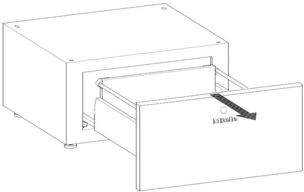
natural_image
Line drawing of a mechanical device with a handle and internal structure, labeled 'Mole' (no text or symbols beyond label)2
text_image
Technical diagram showing assembly steps with magnified views of a mechanical component and a 3D model view.
text_image
A A 4x 4x B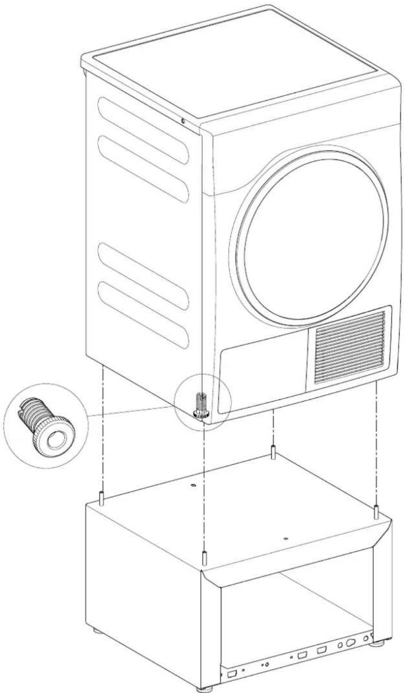
natural_image
Technical line drawing of a washing machine with internal components and mounting base (no text or symbols)natural_image
Empty rectangular frame with corner markers and a central circular symbol (no text or labels)6
text_image
Technical diagram of a mechanical device with labeled components and angular measurement annotation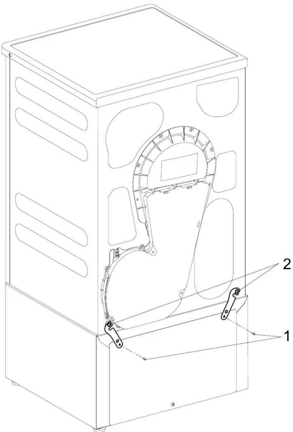
natural_image
Technical line drawing of a mechanical device with internal components and labeled parts (no text or symbols present)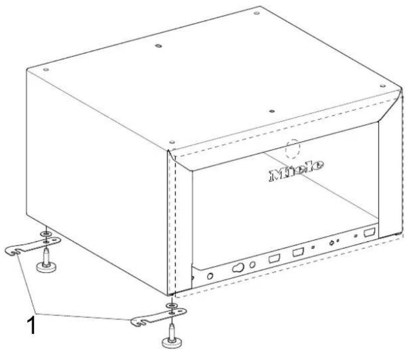
text_image
Mole 19
text_image
Technical diagram of a device casing with labeled components and assembly line10

natural_image
Technical line drawing of a microwave oven with labeled components (no text or symbols beyond basic labels)11
natural_image
Technical line drawing of a rectangular electronic device with mounting holes and internal compartments (no text or symbols)12
text_image
Diagram showing airflow or ventilation process between a device with labeled components A and B, including directional arrows.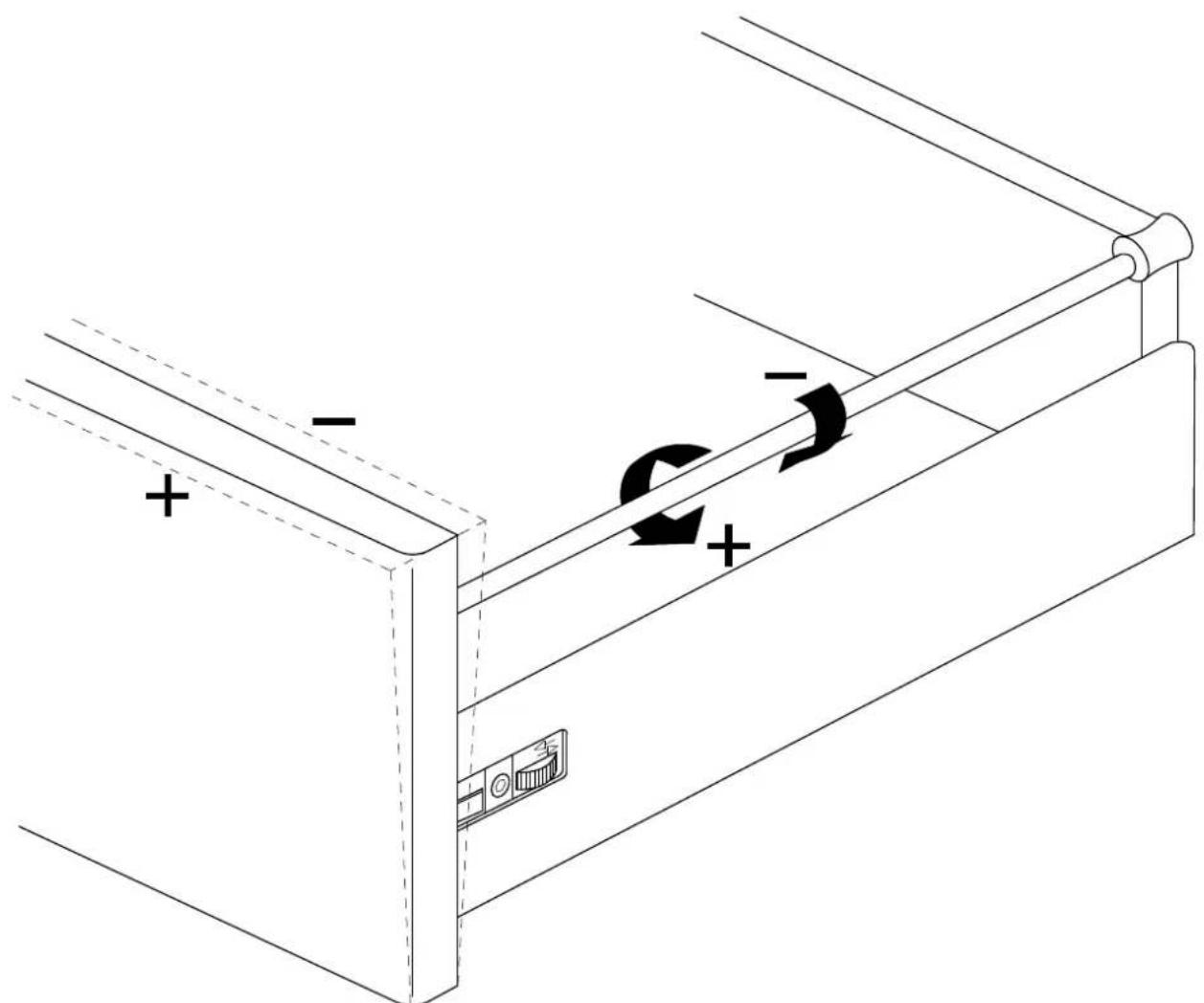
natural_image
Technical line drawing of a mechanical device with directional arrows indicating motion or force (no text or symbols)14
natural_image
Line drawing of a two-wheeled washing machine with labeled doors and internal components (no text or symbols beyond branding)de
WTS510/APCL041 plinth with drawer for washing machines and tumble dryers
Parts required
No. Mat. no. Designation
1 09322300 WTS510 installation kit
1 11477320 APCL041 installation kit
Included parts
No. Mat. no. Designation
1 Installation instructions
1 WTS510/APCL041 plinth
1 Plinth rear panel
2 Connecting piece
4 Spacer sleeve
3 Raised-head screw CEM 4 x 10
4 Threaded pin M10 x 40 mm
10 Adhesive strips for rear panel
1 06593051 Installation kit for floor fastening
Special tool/s
No. Mat. no. Designation
Spirit level
18 mm open spanner or pipe wrench for threaded bolts (square) and dryer feet
Torx T20 screwdriver for rear panel
5 mm Allen key (for tumble dryers only)
Torx T30 screwdriver for screws on the eccentric cam (for tumble dryers only)
Risk of injury during fitting
DANGER

Risk of electric shock. Danger due to live parts.
√ Before any service or repair work is commenced, the machine must be disconnected from the mains.
DANGER

Risk of accident
Fitting can only be carried out with the washing machine or tumble dryer not installed. For deinstallation, see the appropriate operating instructions.
√ Ensure that children or pets cannot access the work area while fitting work is being carried out.
Do not stand, or allow anyone to stand, on the drawer.
DANGER

Risk of crushing
√ Wear slip-proof working gloves and safety shoes.
When carrying out work, ensure that parts of the body, especially the hands and feet, are not positioned under or between machines.
DANGER
There is a risk of injury, particularly spinal injuries, as the machine must be placed on its side for fitting.
The relation of the weight of the machine to the physical strength of the technician must be taken into account. For machine weight details, see the operating instructions.
Risk of injury due to incorrect fitting
WARNING

Risk of accident if machine tips over.
The plinth may only be used with Miele machines.
√ The plinth must not be used with integrated models or a washer-dryer stack combination.
Fasten the washing machine to the plinth.
With a combination with one or more other plinths, individual plinths must be connected together with the connection pieces.
With a single machine installation, secure the plinth to the floor with the floor fastening fitting kit, Mat. no. 06593051.
At least two plinth feet must be bolted to the floor and at least one of these should be at the rear. Fastening of two diagonally opposite feet is ideal.
Danger due to unsuitable materials in the plinth drawer
DANGER

Do not store any inflammable items in the drawer.
NOTE
Wooden parts may swell and/or warp.

Do not store any damp or wet items in the drawer.
Plinth fitting
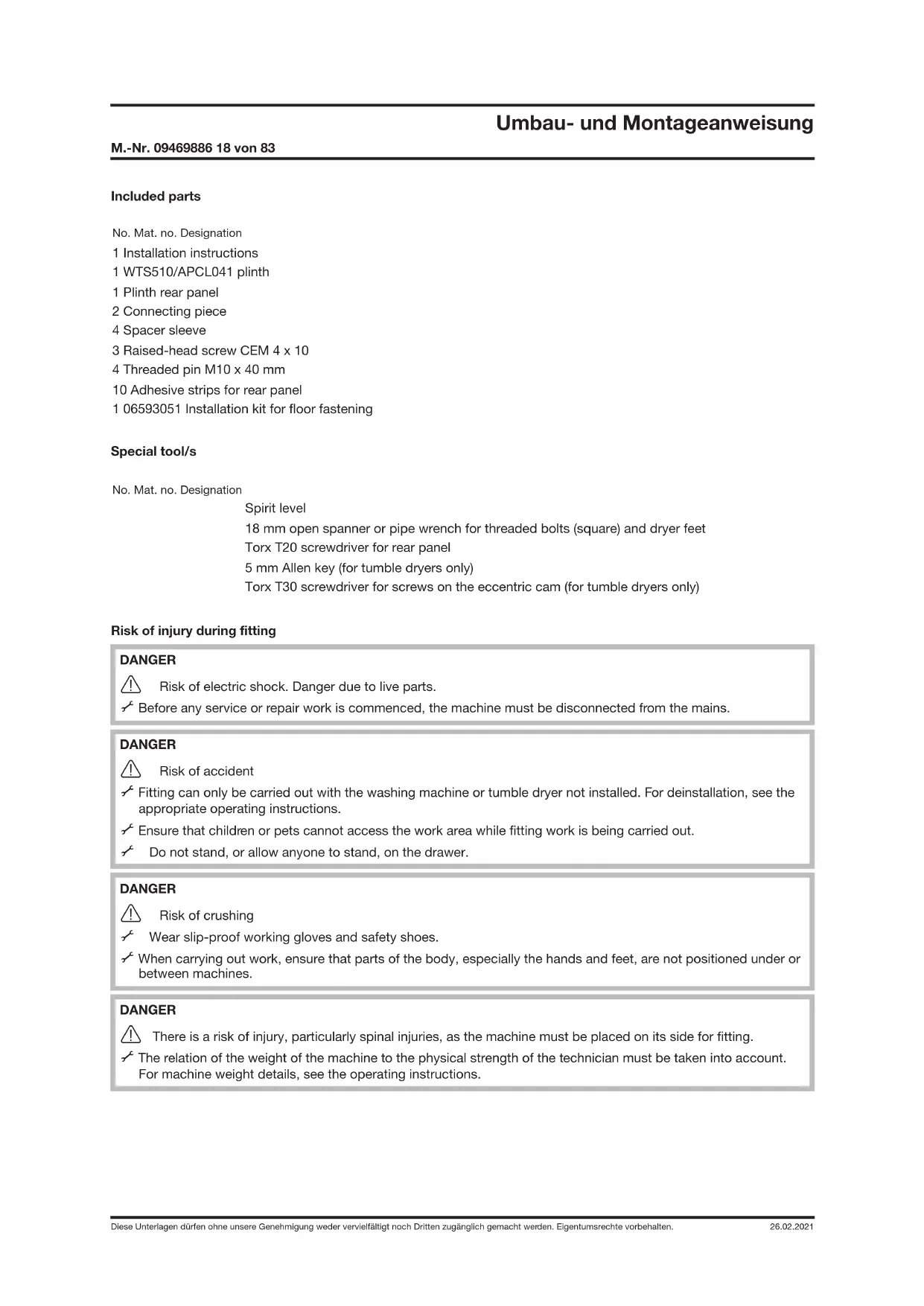
Removal of drawer from plinth
√ Pull out the drawer fully, see Fig. 2.
Press the spring catches and at the same time lift the drawer upwards, see Fig. 3.
Fitting the plinth under a tumble dryer
√ Empty the condensate container drawer.
Screw the dryer feet in fully with a pipe wrench.
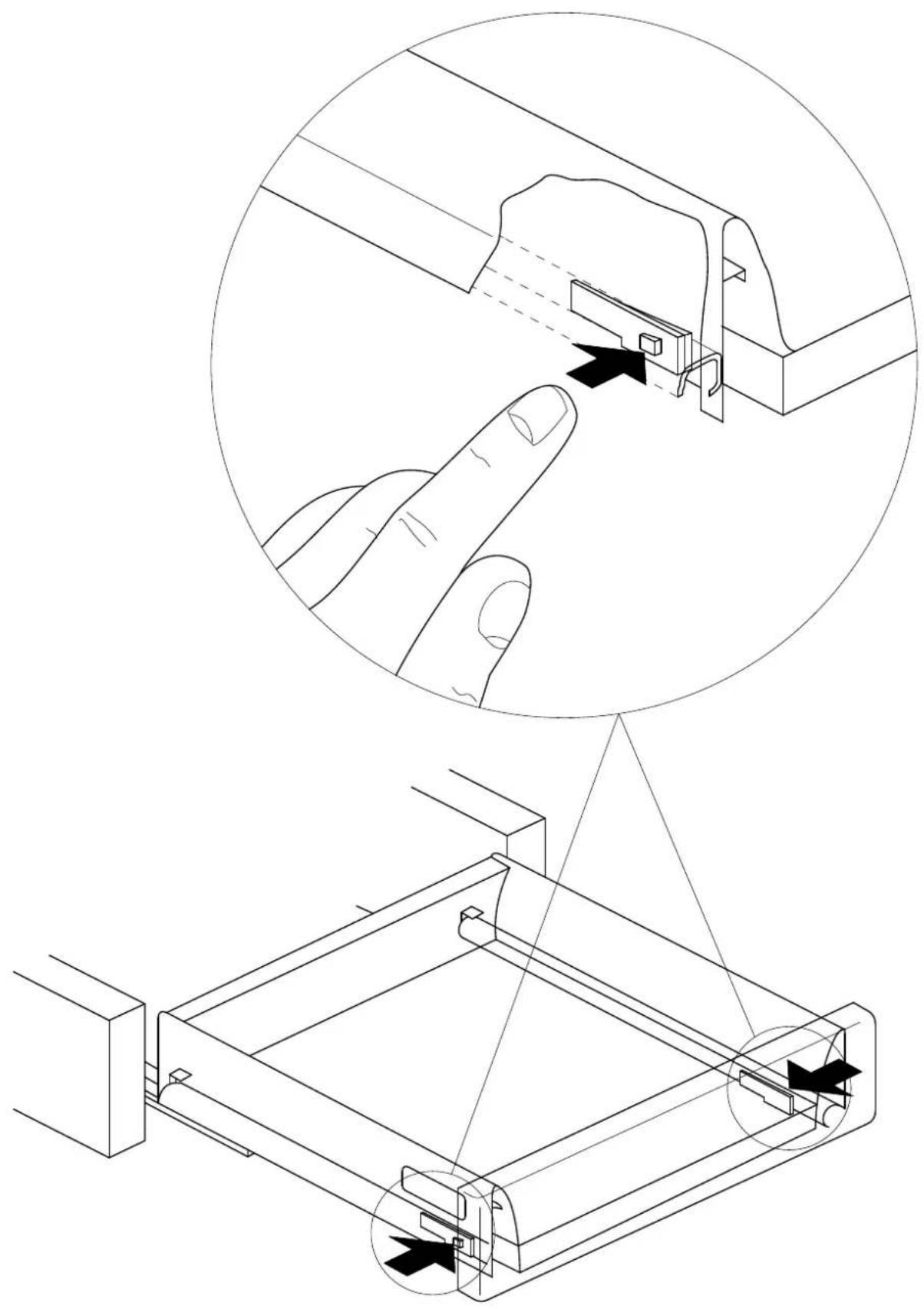
√ Remove the threaded pins from the plinth with a 5 mm Allen key (A) and dispose of them, see Fig. 4.
√ Fit the 10 x 40 mm threaded pins supplied as far as possible into the threaded bolts (B), see Fig. 4.
WARNING

Risk of crushing fingers if they are trapped between the dryer casing and the threaded pins.

Do not lift the dryer at the corners.
√ Lift the dryer onto the plinth and guide the threaded pins into the openings in the dryer feet, see Fig. 5.
Fit the sealing strips as shown on the inside of the rear panel, see Fig. 6.
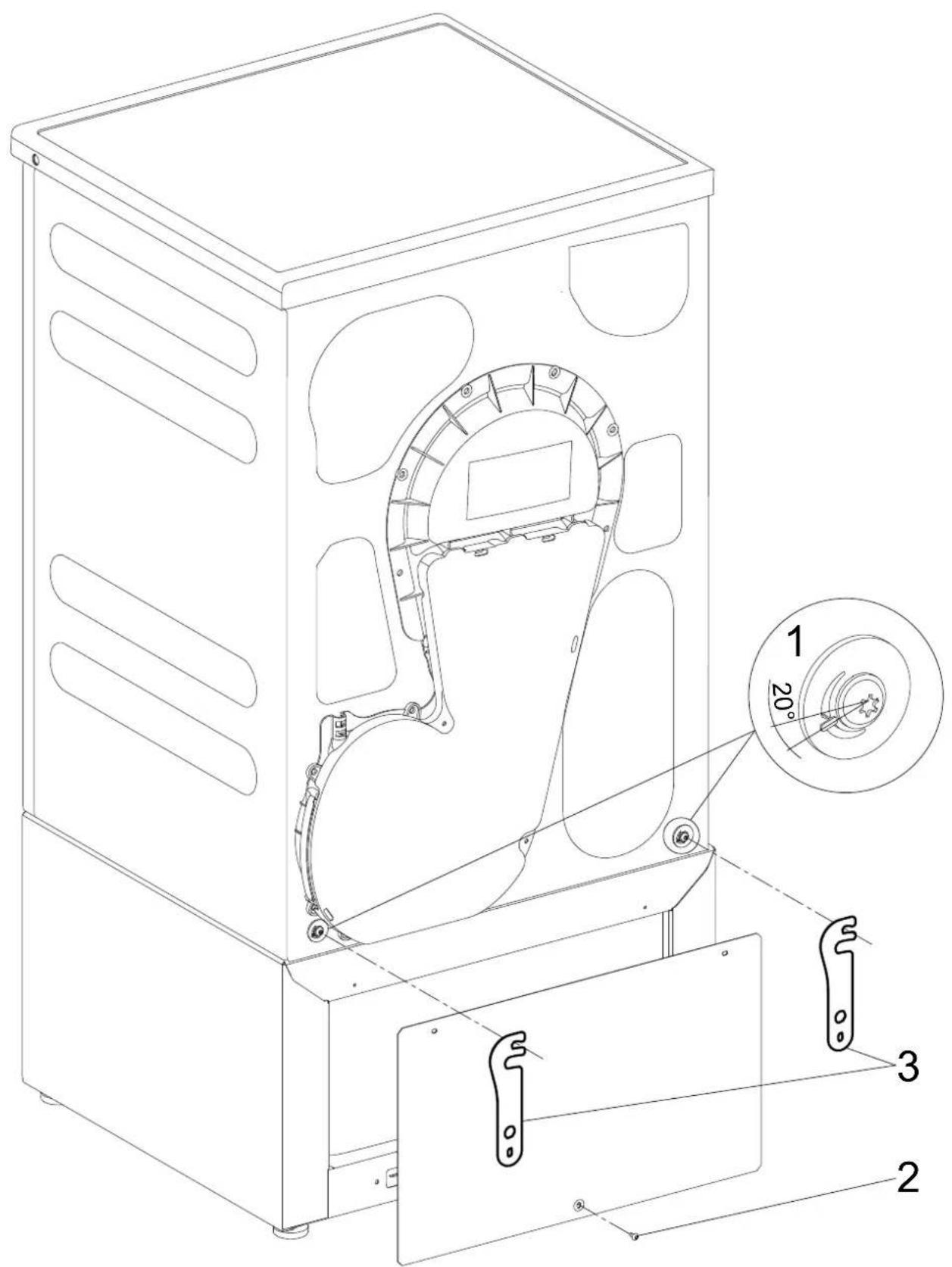
Loosen the screws on the eccentric cam (1) on the dryer rear panel, see Fig. 7
The eccentric cams may move slightly when the screws are loosened. To ensure safe installation, the eccentric cams must be returned to the starting position: Engaging tooth in the bottom left at a 20^ angle (1), see Fig. 7.
Use 1 CEM 4 x 10 raised-head screw to fit the rear panel on the plinth at the bottom (2), see Fig. 7.
Hook the connection pieces (3) onto the screws on the eccentric cams, see Fig. 7.
Use 2 CEM 4 × 10 raised-head screws to fit the connection pieces and the rear panel on the plinth at the top (1), see Fig. 8.
Tighten the screws on the eccentric cams (2), see Fig. 8.
Level the machine and plinth using a spirit level.
Counter the plinth feet.
Secure the plinth to the floor with the floor fastening fitting kit, Mat. no. 06593051.
Installing the plinth under the washing machine
Before the actual assembly, the connection pieces are secured on the plinth. They are used to connect two plinths securely together. Tighten the connection pieces even if a second plinth is not to be used. This will avoid possibly difficult retro fitting and also ensures that the connection pieces are stored safely.
Installation of dryer on left and washing machine on right: See Fig. 9.
Installation of washing machine on left and dryer on right: See Fig. 10.
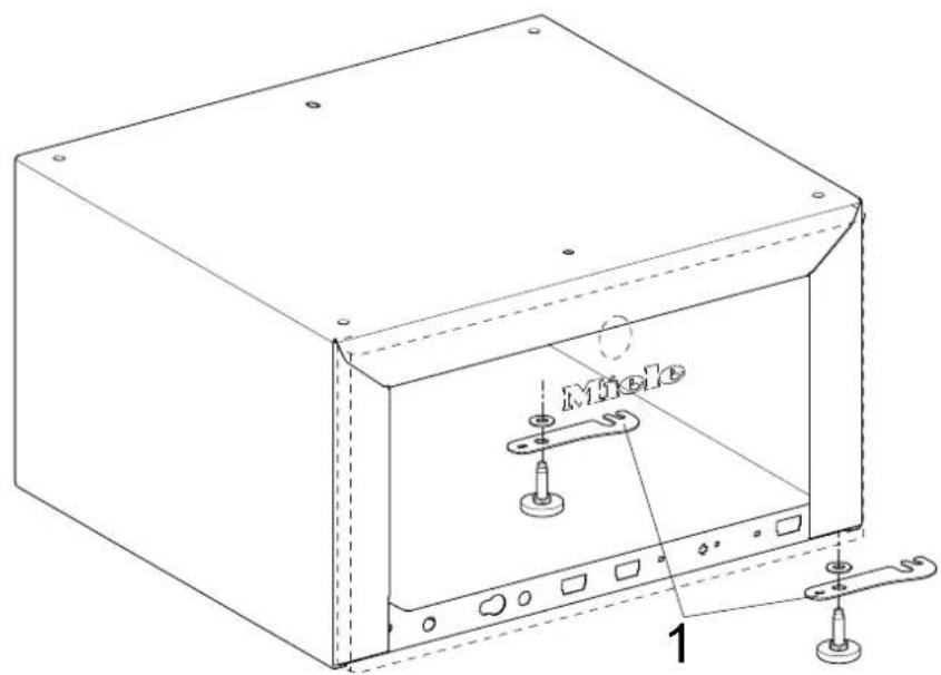
Use a pipe wrench to hold the threaded bolts in the plinth and remove the plinth feet.
Unscrew 2 plinth feet from the left or right side, depending on the installation setup; see Fig. 9 or Fig. 10.
Fit the washers on the drip tray, see Fig. 9 or Fig. 10.
Install the connection pieces (1) on the washers; see Fig. 9 or Fig. 10.
Screw on the 2 plinth feet but don't secure them with the counter nuts yet.
NOTE
Damage to washing machine and flooring.
Drain all water out of the washing machine.
√ Remove the dispenser unit.
√ The washing machine must only be tilted onto its side with the transport struts fitted.
The washing machine must be laid on a flat, soft underlay (e.g. a carpet).
Fit the transport struts if they are not already fitted; see the operating instructions.
Lay the washing machine on its side.
Unscrew and remove the washing machine's feet.
Fit the spacer sleeves (1) on the threaded bolts see Fig. 11.
Connect the plinth and the washing machine together.
√ Tighten the bolts with an open spanner from inside the plinth. Tighten the bolts alternately to ensure even tightening.
Stand the combination upright.
Fit the sealing strips as shown on the inside of the rear panel, see Fig. 6.
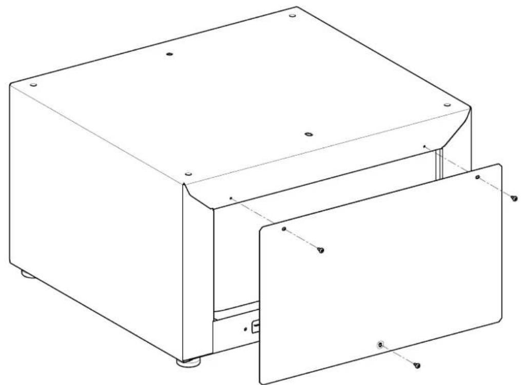
Use 3 CEM 4 x 10 raised-head screws to fit the rear panel on the plinth, see Fig. 12.
Level the machine and plinth using a spirit level.
√ Twist in the connection pieces on the plinth.
Counter the plinth feet.
Secure the plinth to the floor with the floor fastening fitting kit, Mat. no. 06593051.
NOTE
√ Remove the transport struts.
Drawer fitting
Place the drawer on the plinth drawer rails and close the drawer.
→ The drawer audibly locks into position.
To ensure that the drawer is correctly located on the rails, open it again and slam it shut.
Front panel adjustment
The machine front and the front panel of the drawer must be in line with each other. After installation, it may be necessary to adjust the drawer front panel to align it. The height and tilt angle of the drawer front panel can be adjusted.
Open the drawer.
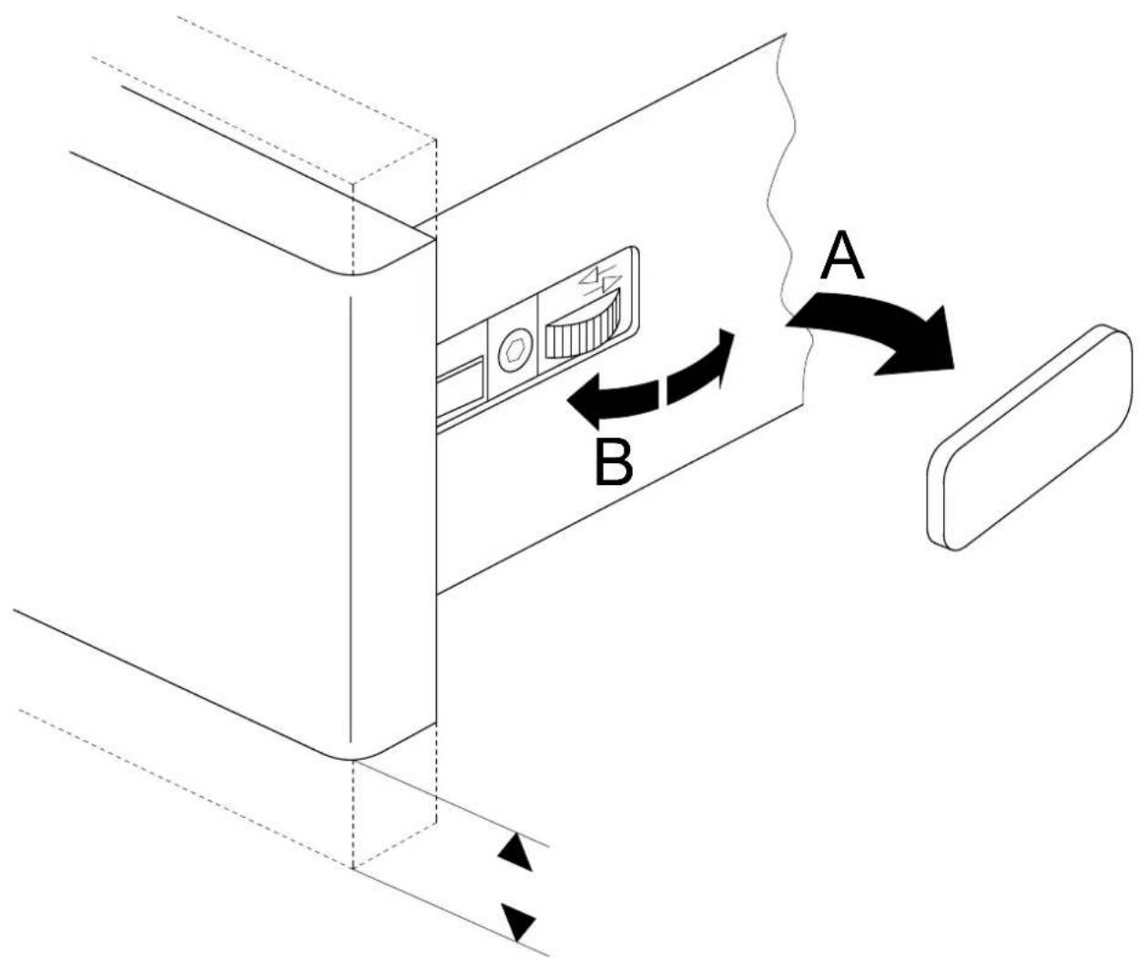
Adjust the height of the front panel:
- Remove the caps (A), see Fig. 13.
- To adjust the height, turn the adjustment wheels on either side as appropriate (B).
- After adjustment, refit the caps.
Adjust the tilt angle of the front panel:
- To adjust the angle, twist the drawer rods as appropriate, see Fig. 14.
Close the drawer.
When installing machines next to each other: connect the plinths
Place the plinths next to each other.
√ Loosen the counter nuts on all plinth feet.
√ Twist out the connection pieces.
Place the connection pieces with their openings on the plinth feet but don't secure them with the counter nuts yet.
The two connected plinths must align with each other at the front.
Plinth feet adjustment
Check with the spirit level.
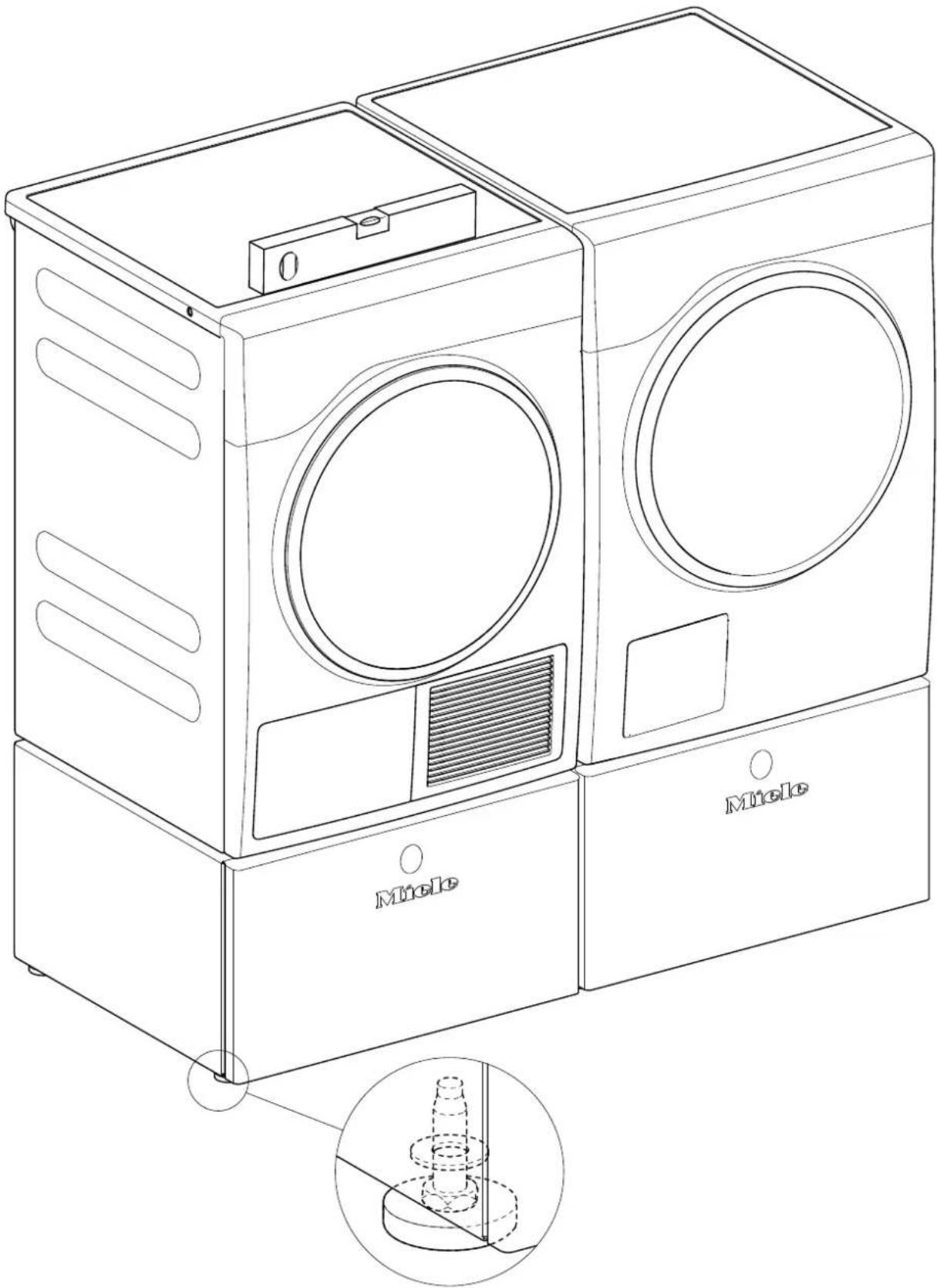
Adjust the plinth feet as appropriate until the plinth is level; see Fig. 15.
With a combination with one or more other plinths: ensure all plinths are the same height.
√ Tighten all counter nuts.
en
cs
WTS 510/APCL 041 stand with drawer for washing machines and tumble dryers
Parts required
Quantity Mat. no. Designation
1 09322300 WTS 510 install kit
1 11477320 APCL 041 install kit
Parts included
Quantity Mat. no. Designation
1 Installation instructions
1 WTS 510/APCL 041 stand
1 Stand rear panel
2 Connection piece
4 Spacer sleeve
3 Raised-head screw, CEM 4 x 10
4 Set screw, M10 x 40 mm
10 Adhesive strips for rear panel
1 06593051 Floor fastening kit
Special tool
Quantity Mat. no. Designation
Level
18mm open wrench, or pipe wrench for threaded bolts (square) and dryer feet
T20 screwdriver for rear panel
5 mm Allen key (for dryer only)
T30 screwdriver for screws on the eccentric cams (for dryer only)
Risk of injury during installation
DANGER
Risk of electric shock. Danger due to live parts.
Before starting any service work, the machine must be disconnected from power.
DANGER
Risk of accident
Installation can only be carried out with the washer or dryer not installed. For uninstallation, see the appropriate operating instructions.
√ Ensure that children or pets cannot access the work area while installation work is being carried out.
Do not stand, or allow anyone to stand, on the drawer.
DANGER
Risk of crushing
√ Wear slip-proof working gloves and safety shoes.
When carrying out work, ensure that body parts, especially hands and feet, are not positioned under or between machines.
DANGER
There is a risk of injury, particularly spinal injuries, as the machine must be placed on its side for installation.
The relation of the weight of the machine to the physical strength of the technician must be taken into account. For machine weight details, see the operating instructions.
Risk of injury due to incorrect installation
WARNING
☐ Risk of accident if machine tips over.
The stand may only be used with Miele machines.
The stand must not be used with integrated models or a washer-dryer stack combination.
Fasten the washing machine to the stand.
When combining with one or more other stands, individual stands must be connected together with the connection pieces.
√ With a single machine installation, secure the stand to the floor with the floor fastening kit, mat. no. 06593051.
At least two stand feet must be bolted to the floor and at least one of these should be at the rear. Fastening of two diagonally opposite feet is ideal.
Danger due to unsuitable materials in the stand drawer
DANGER
Do not store any inflammable items in the drawer.
NOTE
Wooden parts may swell and/or warp.
Do not store any damp or wet items in the drawer.
Stand installation
Removing the drawer from the stand
√ Pull the drawer all the way out; see Fig. 2.
Press the spring catches while lifting the drawer upward; see Fig. 3.
Installing the stand under a dryer
√ Empty the condensate container.
√ Screw the dryer feet in fully with a pipe wrench.
√ Remove the set screws from the stand with a 5 mm Allen key (A); see Fig. 4. These set screws will no longer be needed.
Install the supplied 10 x 40 mm set screws as far as possible into the threaded bolts (B); see Fig. 4.
WARNING

Risk of crushing fingers if they are trapped between the dryer casing and the set screws.

Do not lift the dryer at the corners.
Lift the dryer onto the stand and guide the set screws into the openings in the dryer feet; see Fig. 5.
Install the sealing strips as shown on the inside of the rear panel; see Fig. 6.
√ Loosen the screws on the eccentric cams (1) on the dryer rear panel; see Fig. 7
The eccentric cams may move slightly when their screws are loosened. To ensure safe installation, the eccentric cams must be returned to the starting position: Engaging tooth in the bottom left at a 20^ angle (1); see Fig. 7.
Use 1 CEM 4 x 10 raised-head screw to install the rear panel on the stand at the bottom (2); see Fig. 7.
Hook the connection pieces (3) onto the screws on the eccentric cams; see Fig. 7.
Use 2 CEM 4 x 10 raised-head screws to install the connection pieces and the rear panel on the stand at the top (1); see Fig. 8.
Tighten the screws on the eccentric cams (2); see Fig. 8.
√ Level the machine and stand using a spirit level.
Counter the stand feet.
Secure the stand to the floor with the floor fastening kit, mat. no. 06593051.
Installing the stand under the washer
Before the actual assembly, the connection pieces are secured on the stand. They are used to connect two stands securely together. Tighten the connection pieces even if a second stand is not to be used. This will avoid possibly difficult retrofitting and also ensures that the connection pieces are stored safely.
Installation of dryer on left and washing machine on right: See Fig. 9.
Installation of dryer on left and washing machine on right: See Fig. 10.
Use a pipe wrench to hold the threaded bolts in the stand and remove the stand feet.
√ Unscrew two stand feet from the left or right side, depending on the installation setup; see Fig. 9 or Fig. 10.
Install the washers on the drip pan; see Fig. 9 or Fig. 10.
Install the connection pieces (1) on the washers; see Fig. 9 or Fig. 10.
Screw on the stand feet but don't secure them with the counter nuts yet.
NOTE
Damage to washer and carpeting.
Drain all water out of the washer.
√ Remove the dispensing assembly.
Install the washer's shipping struts before tilting the washer on its side.
The washer must be laid on a flat, soft underlayer (e.g., a carpet).
Install the shipping struts; see the operating instructions.
Lay the washer on its side.
√ Unscrew and remove the washer feet.
Install the spacer sleeves (1) on the set screws; see Fig. 11.
√ Stick the stand and the washer together.
√ Tighten the bolts inside the stand with an open wrench. Tighten the bolts alternately to ensure even tightening.
Stand the washer/stand assembly upright.
Install the sealing strips as shown on the inside of the rear panel; see Fig. 6.
Use 3 CEM 4 x 10 raised-head screws to install the rear panel on the stand; see Fig. 12.
Level the machine and stand using a spirit level.
Twist in the connection pieces on the stand.
Counter the stand feet.
Secure the stand to the floor with the floor fastening kit, mat. no. 06593051.
NOTE
√ Remove the shipping struts.
Drawer installation
Place the drawer on the rails inside the stand and close it.
→ The drawer will audibly lock into place.
To ensure that the drawer is correctly positioned on the rails, open it again and slam it shut.
Front panel adjustment
The machine front and the front panel of the drawer must be in line with each other. After installation, it may be necessary to adjust the drawer front panel to align it. The height and tilt angle of the drawer front panel can be adjusted.
Open the drawer.
Adjust the height of the front panel:
- Remove the cover (A); see Fig. 13.
- To adjust the height, turn the adjustment wheel in the direction of the arrows as appropriate (B).
- When the height has been adjusted appropriately, reinstall the cover.
Adjust the tilt angle of the front panel:
- To adjust the angle, twist the drawer rods as appropriate; see Fig. 14.
Close the drawer.
When installing machines next to each other: Connect the stands
Place the stands next to each other.
√ Loosen the counter nuts on all stand feet.
√ Twist out the connection pieces.
Place the connection pieces with their openings on the stand feet but don't secure them with the counter nuts yet.
The two connected stands must align with each other at the front.
Stand feet adjustment
Use a level.
Adjust the stand feet as appropriate until the stand is level; see Fig. 15.
Multiple-stand combinations: Ensure that all stands are the same height.
√ Tighten all counter nuts.