
XT400 - Walkie-talkie MOTOROLA - Free user manual and instructions
Find the device manual for free XT400 MOTOROLA in PDF.



| Product Type | Walkie-talkie |
| Brand | Motorola |
| Model | XT400 |
| Frequency Band | PMR446 |
| Transmission Power | 0.5 Watts |
| Number of Channels | 16 |
| Antenna | Non-removable |
| Power Supply | Rechargeable lithium-ion battery |
| Battery Life (Standard Battery) | Up to 20 hours (economy mode enabled) |
| Main Features | VOX/iVOX hands-free, channel scanning, encryption, radio cloning, programming via CPS software |
| Maintenance | Clean with a soft damp cloth; do not immerse; do not use alcohol or detergents |
| Safety | Battery and charger safety instructions; RF exposure limited to professional use |
| Included Accessories | Desktop charger, power supply, mains adapters, case |
| Warranty | Motorola Solutions limited warranty |
Frequently Asked Questions - XT400 MOTOROLA
User questions about XT400 MOTOROLA
0 question about this device. Answer the ones you know or ask your own.
Ask a new question about this device
Download the instructions for your Walkie-talkie in PDF format for free! Find your manual XT400 - MOTOROLA and take your electronic device back in hand. On this page are published all the documents necessary for the use of your device. XT400 by MOTOROLA.
USER MANUAL XT400 MOTOROLA
Open Source Software Legal Notices:
This Motorola Solutions product contains Open Source Software. For information regarding licenses, acknowledgements, required copyright notices and other usage terms, refer to the documentation for this Motorola Solutions product at:
http://businessonline.motorolasolutions.com
Go to: Resource Center > Product Information > Manual > Accessories.
CONTENTS
Contents. 1
Computer Software Copyrights .4
Safety 5
Batteries and Chargers Safety Information 6
Operational Safety Guidelines. 7
Radio Overview 9
Parts Of The Radio 9
On/Off/Volume Knob. 10
Channel Selector Knob. 10
Accessory Connector 10
Model Label 10
Microphone 10
Antenna 10
LED Indicator 10
Front Buttons 10
Side Buttons 11
The Lithium-Ion (Li-Ion) Battery 11
Batteries and Chargers 13
Battery Features And Charging Options 13
About the Li-Ion Battery 13
Installing the Lithium-Ion (Li-Ion) Battery 14
Removing the Lithium-Ion (Li-Ion) Battery 14
Power Supply and Drop-in Tray Charger 15
Holster 16
Charging The Battery 16
Charging with the Drop-in Tray Single Unit Charger (SUC) 16
Drop-in Tray Charger LED Indicators . . 18
Battery Meter 19
Estimated Charging Time 20
Getting Started 22
Turning radio ON/OFF 22
Adjusting Volume 22
Reading The Display 22
Selecting a Channel 23
Talking and Monitoring. 23
Receiving a Call 23
Signal Strength Indicator and Channel Busy Indicators 24
Talk Range. 24
Radio LED Indicators 26
26
Hands-Free Use/VOX 27
With Compatible VOX Accessories. 27
Setting iVOX Sensitivity 27
Microphone Gain. 28
Hands Free without Accessories (iVOX).28
Toggle Voice Prompt in User Mode . . .28
Power Up - Tone Mode. 28
Reset to Factory Defaults 28
Keypad Beeps. 29
Keypad Lock/Unlock. 29
Menu Options 29
Setting VOX /iVOX Sensitivity - Menu .29
Setting VOX /iVOX Sensitivity - CPS . . .30
Microphone Gain Menu. 30
Microphone Accessory Gain Level . . . .31
Call Tones. 32
Scan List Menu 33
Programming Features 34
Advanced Configuration Mode 34
Programming Rx (Reception) Frequencies .35
Programming Rx (Reception) Codes (CTCSS/DPL). 35
Programming Scramble. 36
Scan 37
Programming Scan List 38
Editing Channel Alias Name 39
Nuisance Channel Delete 40
Customer Programming Software (CPS) . . . 40
Time-Out Timer 41
Reverse Burst 41
Cloning Radios. 42
Cloning with a Multi-Unit Charger (MUC) 42
CPS and Cloning Cables (Optional Accessory) 44
Cloning Radio using the Radio to Radio (R2R) Cloning Cable (Optional Accessory) 45
Cloning using the Customer Programming Software (CPS) 47
Troubleshooting 48
52
Use and Care 52
Frequency and Code Charts 53
CTCSS and PL/DPL Codes 55
Motorola Solutions Limited Warranty 60
Accessories 62
Audio Accessories 62
Battery 62
Cables 62
Chargers 62
Carry Accessories 63
COMPUTER SOFTWARE
The Motorola Solutions products described in this manual may include copyrighted Motorola Solutions computer programs stored in semiconductor memories or other media. Laws in the United States and other countries preserve for Motorola Solutions certain exclusive rights for copyrighted computer programs, including, but not limited to, the exclusive right to copy or reproduce in any form the copyrighted computer program. Accordingly, any copyrighted Motorola Solutions computer programs contained in the Motorola Solutions products described in this manual may not be copied, reproduced, modified, reverse-engineered, or distributed in any manner without the express written permission of Motorola Solutions.
Furthermore, the purchase of Motorola Solutions products shall not be deemed to grant either directly or by implication, estoppel, or otherwise, any license under the copyrights, patents or patent applications of Motorola Solutions, except for the normal non-exclusive license to use that arises by operation of law in the sale of a product.
English
SAFETY
PRODUCT SAFETY AND RF EXPOSURE COMPLIANCE

Caution
Before using this product, read the operating instructions and RF energy awareness information contained in the Product Safety and RF Exposure booklet enclosed with your radio.
ATTENTION!
This radio is restricted to occupational use only to satisfy FCC/ICNIRP RF energy exposure requirements.
For a list of Motorola Solutions-approved antennas, batteries and other accessories, visit the following website which lists approved accessories:
www.motorolasolutions.com
BATTERIES AND CHARGERS SAFETY INFORMATION
This document contains important safety and operating instructions. Read these instructions carefully and save them for future reference. Before using the battery charger, read all the instructions and cautionary markings on
the charger, the battery, and the radio using the battery
- To reduce risk of injury, charge only the rechargeable Motorola Solutions-authorized batteries. Other batteries may explode, causing personal injury and damage.
- Use of accessories not recommended by Motorola Solutions may result in risk of fire, electric shock, or injury.
- To reduce risk of damage to the electric plug and cord, pull by the plug rather than the cord when disconnecting the charger.
- An extension cord should not be used unless absolutely necessary. Use of an improper extension cord could result in risk of fire and electric shock. If an extension cord must be used, make sure that the cord size is 18AWG for lengths up to 100 feet (30.48 m), and 16AWG for lengths up to 150 feet (45.72 m).
- To reduce risk of fire, electric shock, or injury, do not operate the charger if it has been broken or damaged in any way. Take it to a qualified Motorola Solutions service representative.
- Do not disassemble the charger; it is not repairable and replacement parts are not available. Disassembly of the charger may result in risk of electrical shock or fire.
- To reduce risk of electric shock, unplug the charger from the AC outlet before attempting any maintenance or cleaning.
OPERATIONAL SAFETY GUIDELINES
- Turn the radio OFF when charging battery.
- The charger is not suitable for outdoor use. Use only in dry locations/conditions.
- Connect charger only to an appropriately fused and wired supply of the correct voltage (as specified on the product).
- Disconnect charger from line voltage by removing main plug.
- The outlet to which this equipment is connected should be nearby and easily accessible.
- In equipment using fuses, replacements must comply with the type and rating specified in the equipment instructions.
- Maximum ambient temperature around the power supply equipment must not exceed 40°C (104°F) .
- Power output from the power supply unit must not exceed the ratings stated on the product label
located at the bottom of the charger.
- Make sure that the cord is located where it will not be stepped on, tripped over, or subjected to water, damage, or stress.
Notes
RADIO OVERVIEW
PARTS OF THE RADIO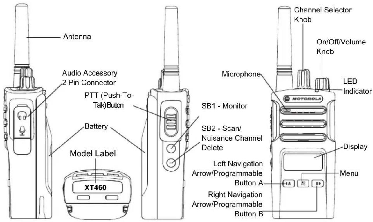
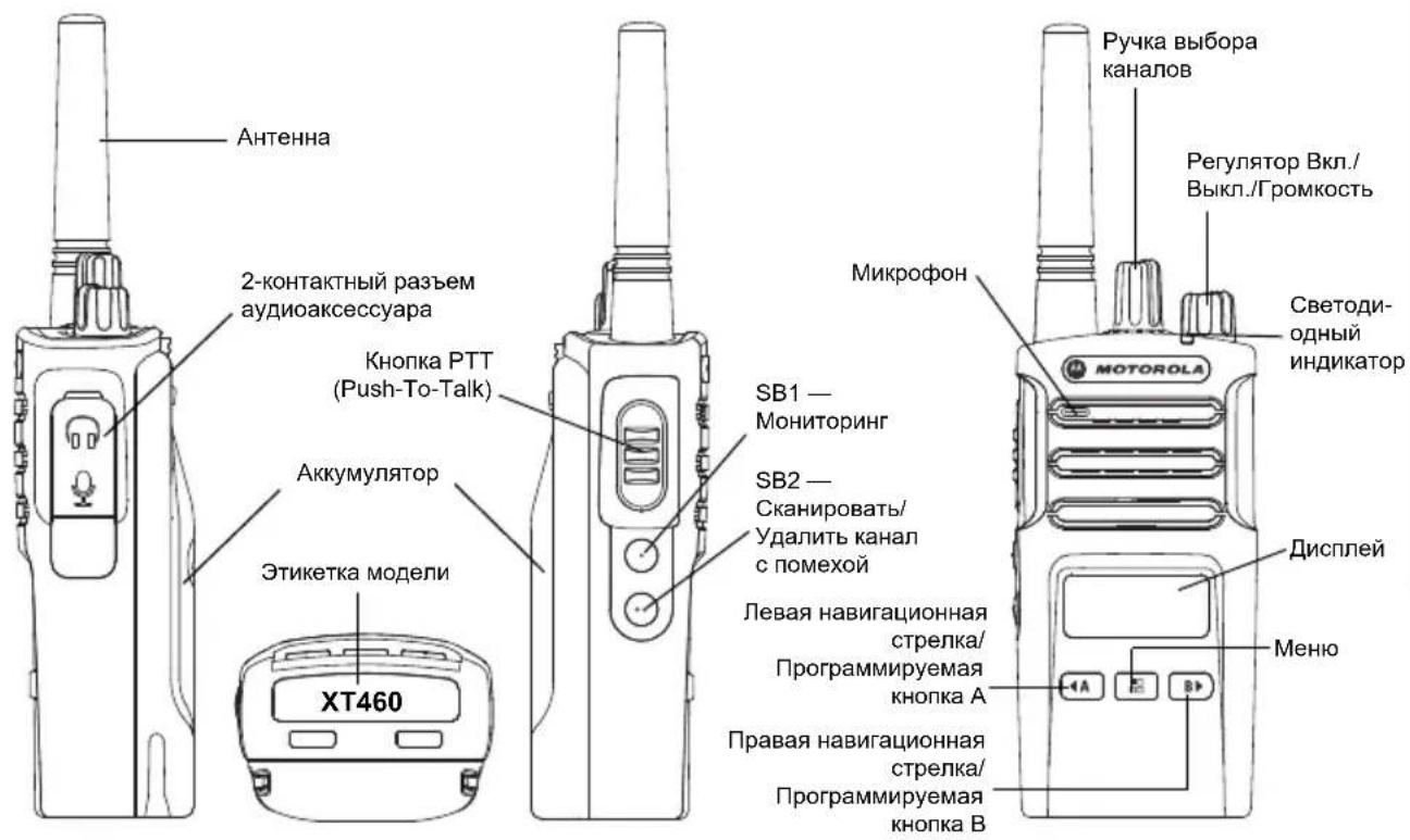
On/Off/Volume Knob
Used to turn the radio ON or OFF and to adjust the radio's volume.
Channel Selector Knob
Used to switch the radio to different channels.
Accessory Connector
Used to connect compatible audio accessories.
Model Label
Indicates the model of the radio.
Microphone
Speak clearly into the microphone when sending a message.
Antenna
For model XT460, the antenna is non-removable.
LED Indicator
Used to give battery status, power-up status, radio call information and scan status.
Front Buttons
Menu Button
Gives access to set up features like VOX/iVOX levels, etc.
It also allows you to move through all the features while in Programming Mode.
Programmable Button
Allows you to choose level or toggle options for features the Menu is on.
Default set to generate current programmed call tone.
Programmable Button
Allows you to choose level or toggle options for features the Menu is on.
Default set to Backlight Mode.
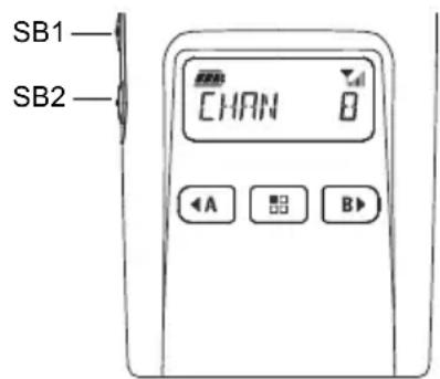
Note: Buttons, , SB1 and SB2 are
programmable. For example: Scramble, Scan/Nuisance Channel Delete, Monitor and Call Tones. To learn more about how to program these buttons, refer to "Customer Programming Software (CPS)" on page 40.
Side Buttons
Push-to-Talk (PTT) Button
- Press and hold down this button to talk, release it to listen.
Side Button 1 (SB1)
- The Side Button 1 is a general button that can be configured by the Customer Programming Software - CPS. The SB1 default setting is 'Monitor'.
Side Button 2 (SB2)
- The Side Button 2 is a general button that can be configured by the CPS. The SB2 default setting is 'Scan/Nuisance Channel Delete'.
The Lithium-Ion (Li-Ion) Battery
XT Series comes with a Standard Capacity Li-Ion battery. Other batteries may be available.
For more information, see "Battery Features"
And Charging Options" on page 13.
This User Guide covers the XT460 model from the XT Series radios. The radio's model is shown on the bottom of the radio and provides the following information:
Table 1: XT460 Radio Specifications
| Model | Frequency Band | Transmit Power (Watts) | Number of Channels | Antenna |
| XT460 PMR446 0.5 16 Non-removable | ||||
BATTERIES AND CHARGERS
XT Series radios provide Lithium-Ion batteries that come in different capacities that define the battery life.
BATTERY FEATURES AND CHARGING OPTIONS
About the Li-Ion Battery
The XT Series radio comes equipped with a rechargeable Li-Ion battery. This battery should be fully charged before initial use to ensure optimum capacity and performance.
Battery life is determined by several factors. Among the more critical are the regular overcharge of batteries and the average depth of discharge with each cycle. Typically, the greater the overcharge and the deeper the average discharge, the fewer cycles a battery will last. For example, a battery which is overcharged and discharged 100% several
times a day, lasts fewer cycles than a battery that receives less of an overcharge and is discharged to 50% per day. Further, a battery which receives minimal overcharging and averages only 25% discharge, lasts even longer.
Motorola Solutions batteries are designed specifically to be used with a Motorola Solutions charger and vice versa. Charging in non-Motorola Solutions equipment may lead to battery damage and void the battery warranty. The battery should be at about 77°F (25°C) (room temperature), whenever possible. Charging a cold battery (below 50°F [10°C]) may result in leakage of electrolyte and ultimately in failure of the battery. Charging a hot battery (above 95°F [35°C]) results in reduced discharge capacity, affecting the performance of the radio. Motorola Solutions rapid-rate battery chargers contain a temperature-sensing circuit to ensure that
batteries are charged within the temperature limits stated above.
Installing the Lithium-Ion (Li-Ion) Battery 1. Turn OFF the radio. 2. With the Motorola Solutions logo side up on the battery pack, fit the tabs at the bottom of the battery into the slots at the bottom of the radio's body. 3. Press the top part of the battery towards the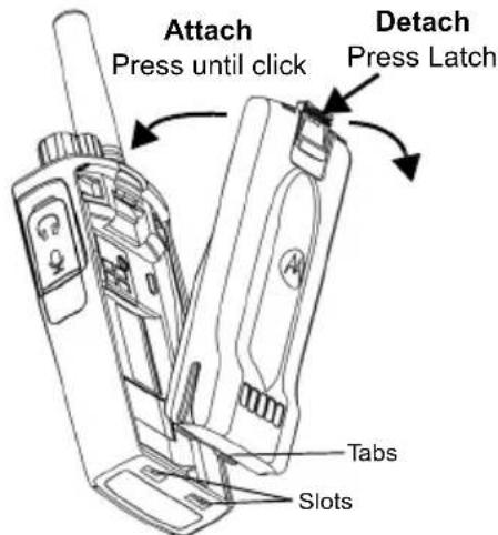
radio until a click is heard.
Note: To learn about the Li-Ion Battery Life features, refer to "About the Li-Ion Battery" on page 13
Removing the Lithium-Ion (Li-Ion) Battery
- Turn OFF the radio.
- Push down the battery latch and hold it while removing the battery.
- Pull the battery away from the radio.
Table 1: Li-Ion Battery Life with Tx Power 0.5 Watts
| Battery Type | Battery Save OFF | Battery Save ON |
| Standard 16 Hours 20 Hours | ||
| High Capacity N/A N/A | ||
English
Power Supply and Drop-in Tray Charger
Drop-in Tray Charger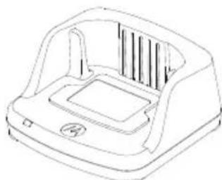
Power Supply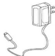
Your radio comes with one Drop-in Tray Charger and one Power Supply (also known as Transformer) and a set of adaptors.
Your Power Supply is capable of switching to suit any of the adaptors that comes with your radio package.
The Adaptor you install depends on the region you're located.
Once you have identified the Adaptor that matches your electrical outlet, proceed to install it as follows:
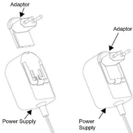
- Slide down the Adaptor grooves into the Power Supply until it snaps into place.
- Slide the Adaptor upward to remove.
Note: The adaptor shown in the pictures are for illustration purposes only. The adaptor you install may be different.
When acquiring additional Charger or Power Supply, make sure you have the similar Drop-in Tray Charger and Power Supply set.
Holster
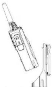
- Insert the radio into the base of the holster at an angle. Press the radio against the back of the holster until the hooks on the holster are inserted in the top recesses of the battery.
- To remove, using the top tab on the holster, detach the hooks of the holster from the top recesses of the battery. Slide the radio at an angle and remove from the holster.
CHARGING THE BATTERY
To charge the battery (with the radio attached), place it in a Motorola Solutions approved Drop-in Tray Single Unit Charger or Multi-Unit Charger.
Charging with the Drop-in Tray Single Unit Charger (SUC)
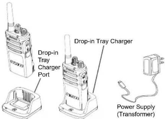
- Place the Charger on a flat surface.
- Insert the connector of the Power Supply into the port on the side of the Charger.
- Plug the AC Adaptor into a power outlet.
- Insert the radio into the Charger with the radio facing the front, as shown.
Note: When charging a battery attached to a radio, turn the radio OFF to ensure a full charge. See "Operational Safety Guidelines" on page 7 for more information.
Charging A Stand-Alone Battery
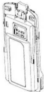
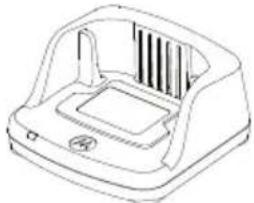
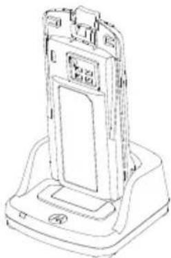
To charge only the battery - at step 4 on page 16, insert the battery into the tray, with the inside surface of the battery facing the front of the Drop-in Tray Single Unit Charger as shown above. Align the slots in the battery with the alignment ribs in the Drop-in Tray Single Unit Charger.
Table 2: Motorola Solutions Authorized Batteries
| Part Number Description | |
| PMNN4434_R Standard Li-Ion Battery | |
| PMNN4453_R | High Capacity Li-Ion Battery |
Drop-in Tray Charger LED Indicators
Table 3: Charger LED Indicator
| Status LED Indicator Comments | ||
| Power On | Green for approximately 1 second | |
| Charging | Steady Red | |
| Charging Complete | Steady Green | |
| Battery Fault (*) | Red Fast Flash | |
| Waiting to Charge (**) | Amber Slow Flash | |
| Battery Level Status | N/A Battery empty | |
| Flash Red 1 Time | Battery low | |
| Flash Amber 2 Times | Battery medium | |
| Flash Green 3 Times | Battery High | |
( ) Normally, re-positioning the battery pack will correct this issue. ( *) Battery temperature is too warm or too cold or wrong power voltage is being used.
If there is NO LED indication:
English
- Check if the radio with battery, or the battery alone, is inserted correctly. (refer to step 4 of "Charging with the Drop-in Tray Single Unit Charger (SUC)" on page 16)
- Ensure that the power supply cable is securely plugged into the charger socket using an appropriate AC outlet and there is power to the outlet.
- Confirm that the battery being used with the radio is listed in Table 2.
Battery Meter
The battery meter located in the upper left corner of the radio display indicates how much battery power the radio has remaining.
Table 4: XT460 Battery Meter
| Battery Type | Battery Meter | ||
| 3 Bars 2 Bars | 1 Bar | ||
| Li-Ion | |||
| 100 – 70% 70 – | 30% | 35 – 0% (≤ 10% when blinking) | |
English
Rated Charging Time
The following table provides the estimated charging time of the battery. For more information, see "Battery" on page 62.
Table 5: Battery Estimated Charging Time
| Charging Solutions | Estimated Charging Time | |
| Standard Battery High Capacity Battery | ||
| Standard ≤ 4.5 Hours N/A | ||
| Rapid ≤ 2.5 Hours N/A | ||
Charging a Radio and Battery using a Multi-Unit Charger (MUC) (Optional Accessory)
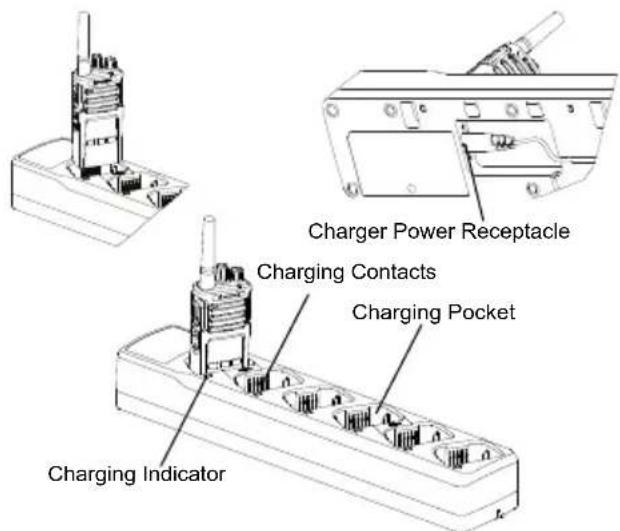
The Multi-Unit Charger (MUC) allows drop-in charging of up to 6 radios or batteries. Batteries can be charged with the radios or removed and placed in the MUC separately. Each of the 6 charging pockets can hold a radio (with or without the Holster) or battery, but not both.
- Place the MUC on a flat surface.
- Insert the power cord plug into the MUC's dual pin connector at the bottom of the MUC.
- Plug the power cord into an AC outlet.
- Turn the radio OFF.
- Insert the radio or battery into the charging pocket with the radio or battery facing away from the contacts.
Note:
- This MUC clones up to 2 radios (2 Source radios and 2 Target radios). Refer to "Cloning with a Multi-Unit Charger (MUC)" on page 42 for more information.
- More information on the MUC's operation is available in the Instruction Sheets provided with the MUC. For more information on the parts and their part numbers, refer to "Accessories" on page 62. Refer to Table 3 on page 18 for more information on the MUC's LED Indicators.
GETTING STARTED
For the following explanations, refer to "Parts Of The Radio" on page 9.
To turn ON the radio, rotate the On/Off/Volume Knob clockwise. The radio plays one of the following:
- Power up tone and channel number announcement, or
- Battery level and channel number announcements, or
- Silent (audible tones disabled). The LED blinks red briefly.
To turn the radio OFF, rotate the On/Off/Volume Knob counterclockwise until you hear a 'click' and the radio LED Indicator turns OFF.
ADJUSTING VOLUME
Turn the On/Off/Volume Knob clockwise to increase the volume, or counterclockwise to decrease the volume.
Note: Do not hold the radio too close to the ear when the volume is high or when adjusting the volume.
READING THE DISPLAY
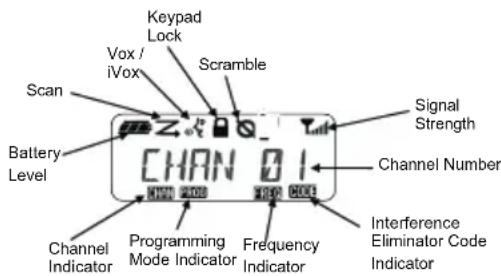
Note: The radio display shown here is for icon location only. Each radio display may appear different (channel and code) based on the pre-programmed radio defaults and features available in the model or region. Pressing any button, except the PTT button, will turn on the backlight.
SELECTING A CHANNEL
To select a channel, turn the Channel Selector Knob until you reach the desired channel. An audible voice indicates the selected channel.
Each channel has its own Frequency, Interference Eliminator Code and Scan Settings.
TALKING AND MONITORING
It is important to monitor for traffic before transmitting to avoid 'talking over' someone who is already transmitting.
To monitor, long press and hold the SB1(*) button to access channel traffic. If no activity is present, you will hear 'static'. To release, press SB1 again. Once channel traffic has cleared, proceed with your call by pressing the PTT button. When transmitting, the LED Indicator stays solid red.
Notes:
- To listen to all activity on a current channel, short press the SB1 to set the CTCSS/DPL code to 0. This feature is called 'CTCSS/DPL Defeat (Squelch set to SILENT)'.
- (* This assumes SB1 is not being programmed for a different mode.)
RECEIVING A CALL
- Select a channel by rotating the Channel Selector Knob until you reach the desired channel.
- Make sure the PTT button is released and listen for voice activity.
- The LED Indicator stays solid red when the radio is receiving a call.
- To respond, hold the radio vertically 1 to 2 inches (2.5 to 5cm) from your mouth. Press the PTT button to talk; release it to listen.
Note: The LED stays solid red when the radio is receiving or transmitting.
Signal Strength Indicator and Channel Busy Indicators
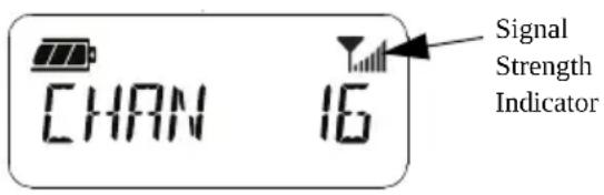
When there is activity on a frequency, the radio blinks the Signal Strength Indicator icon
(without the bars) and the radio LED stays solid orange. The radio Signal Strength Indicator icon can change from 1 (weakest) to 6 (strongest) depending on the radio reception coverage. When the radio is in receiving mode, the radio displays the Signal Strength Indicator icon with bars.
Note: Obstacles blocking the signal path affect the strength of the incoming signal.
TALK RANGE
XT Series radios have been designed to maximize performance and improve
transmission range in the field. It is recommended that you do not use the radios closer than 1.5 meters apart, to avoid
interference. XT460 coverage is 16,250 square meters, 13 floors and 9 km in flat areas.
Talk range depends on the terrain. It is affected by concrete structures, heavy foliage and by operating radios indoors or in vehicles. Optimal range occurs in flat, open areas with up to 9 kilometers of coverage. Medium range occurs when buildings and trees are in the way. Minimal range occurs when dense foliage and mountains obstruct the communication path.
To establish a proper two-way communication, the Channel, Frequency and Interference Eliminator Codes must be the same on both radios. This depends on the stored profile that has been pre-programmed on the radio:
- Channel: Current channel that the radio is using, depending upon radio model.
- Frequency: The frequency the radio uses to transmit/receive.
- Interference Eliminator Code: These codes help minimize interference by providing a choice of code combinations.
- Scramble Code: Codes that make the transmissions sound garbled to anyone listening who is not set to that specific code.
For details of how to set up frequencies and CTCSS/DPL codes in the channels, refer to "Advanced Configuration Mode" on page 34.
RADIO LED INDICATORS
| RADIO STATUS LED INDICATION | |
| Channel Alias Edit Red Heartbeat | |
| Channel Busy Solid Orange | |
| Cloning Mode Double Orange Heartbeats | |
| Cloning In Progress Solid Orange | |
| Fatal Error at Power up | One Green Blink, One Orange Blink, One Green Blink, then repeat for 4 seconds |
| Low Battery Orange Heartbeat | |
| Low Battery Shutdown Fast Orange Heartbeat | |
| Monitor LED is OFF | |
| Power-Up Solid Red for 2 seconds | |
| ‘Idle’ Programming Mode / Channel Mode | Green Heartbeat |
| Scan Mode Fast Red Heartbeat | |
| Transmit (Tx)/Receive (RX) Solid | Red |
| VOX/iVOX Mode Double Red Heartbeats | |
English
HANDS-FREE USE/VOX
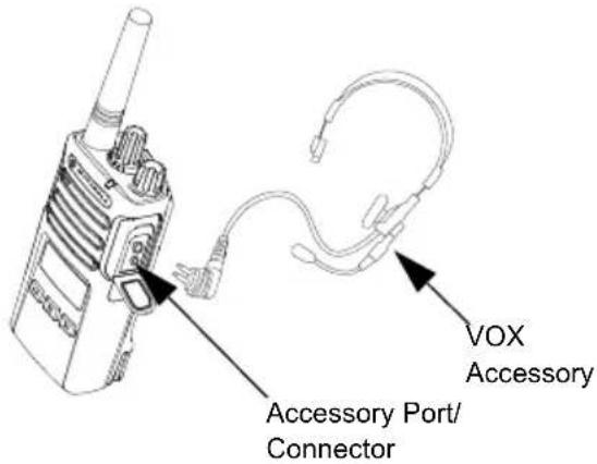
Motorola Solutions XT Series radios can operate hands-free (VOX) when used with compatible VOX accessories.
With Compatible VOX Accessories
The default factory setting for VOX sensitivity level is Medium ('2'). Before using VOX, use the Customer Programming Software (CPS) to set the VOX sensitivity level to a different level from '2'. Then, perform the following steps:
- Turn the radio OFF.
- Open accessory cover.
- Insert the audio accessory's plug firmly into accessory port.
- Turn radio ON. The LED Indicator blinks double red.
- Lower radio volume BEFORE placing accessory near ear.
- To transmit, speak into accessory microphone and to receive, stop talking.
- VOX can be temporarily disabled by pressing the PTT button or by removing the audio accessory.
VOX can also be activated using the (Menu) button without using the CPS.
Note: To order accessories, contact your Motorola Solutions point of purchase
Setting iVOX Sensitivity
The sensitivity of the radio's accessory or microphone can be adjusted to suit different operating environments. iVOX sensitivity can be programmed via the CPS or the (Menu) button.
Default value is "3". iVOX can be set to any value as listed below:
- 1 = High audio input levels trigger the Tx
- 2 = Medium sensitivity
- 3 = Low audio input levels trigger the Tx
Microphone Gain
The sensitivity of the microphone can be adjusted to fit different users or operating environments.
This feature can be adjusted using the (Menu) button or the CPS. Microphone default setting is set to level 2 (medium gain).
Hands Free without Accessories (iVOX)
Press the PTT button while turning ON the radio to enable iVOX. The icon b i n - iVOX can be temporarily disabled by pressing the PTT button. - A short press of the PTT Button re-enables iVOX.
Note:
- There is a short delay between the time when you start talking and when the radio transmits.
- For more information on setting VOX/iVOX sensitivity, refer to "Setting VOX /iVOX Sensitivity - Menu" on page 29.
Toggle Voice Prompt in User Mode
Short press the SB1 Button while turning ON the radio to enable/disable the Voice Prompt in User Mode. (Default is set to ON).
Power Up - Tone Mode
To enable/disable power up tone mode, press SB1 and SB2 buttons simultaneously for 2-3 seconds while powering up the radio until you hear a quick series of beeps and the power up voice announcement programmed.
Reset to Factory Defaults
Reset to Factory Defaults sets back all radio features to the original factory default settings. To do so, press PTT, SB2 and SB1 simultaneously while turning ON the radio until you hear a high tone chirp.
Keypad Beeps
To enable/disable Keypad Beeps, short press the SB2 button while turning ON the radio until you hear a 'chirp' tone.
Keypad Lock/Unlock
You can lock the keypad to avoid accidentally changing your radio settings. To lock the radio keypad, press and hold the menu button for 4 seconds.
Note: The PTT Button and Programmable Button A (if Call Tone feature has been assigned) cannot be locked using this feature.
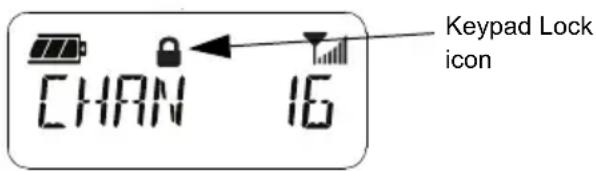
MENU OPTIONS
To access the radio MENU, short press the Menu button. The radio displays the feature options. For each option, use the up and down buttons to navigate. After selecting your desired option settings, you can:
- press the Menu button to save and go to the next option, or
- long press the PTT button to save and exit, or
- turn OFF the radio to exit without saving the changes.
The MENU mode times out automatically if there is no activity detected for more than 10 seconds.
Setting VOX /iVOX Sensitivity - Menu
The VOX/iVOX sensitivity settings can be adjusted via the MENU as well as the CPS. To modify via the MENU, make sure you have enabled VOX or iVOX. (Refer to "Hands-Free Use/VOX" on page 27 or "Hands Free without
Accessories (iVOX)" on page 28 for more information). Once VOX/iVOX is enabled, short press the Menu button.
If iVOX is enabled when you press the Menu button, the radio displays the following:
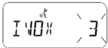
If VOX is enabled (with accessory connected to the radio) when you press the (Menu) button, the radio displays the following:
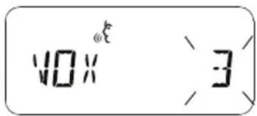
Setting VOX /iVOX Sensitivity - CPS
The sensitivity of the radio's accessory or microphone can be adjusted during VOX/iVOX operation to suit different operation environments. VOX/iVOX sensitivity can be programmed via the CPS.
Microphone Gain Menu
The sensitivity of the microphone can be adjusted to fit different users or operating environments.
Press the (Menu) button until the radio displays the solid letters 'IMIC', VOX icon and blinks the current microphone gain level as follows:
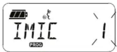
Press the and buttons to toggle through the Microphone Gain settings:
- 1 = Low gain
- 2 = Medium gain
- 3 = High gain
Once you have selected the desired Microphone Gain Level, press the (Menu) button to save and proceed to the next step, or turn OFF the radio to exit without saving changes. Microphone gain can also be configured using CPS.
Microphone Accessory Gain Level
The Microphone Gain Level for the accessory can be configured in the Microphone Accessory Gain Menu. Press the (Menu) button until the radio displays the solid letters "MIC", VOX icon and blinks the current radio accessory Microphone Gain as follows:
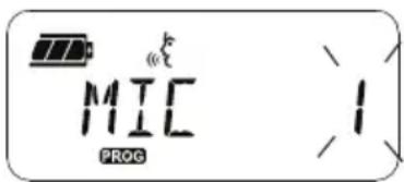
Press the and buttons to toggle through the Accessory Microphone Gain settings and select the desired Microphone Accessory Gain Level
- 1 = Low gain
- 2 = Medium gain
- 3 = High gain
Once you have selected the desired Microphone Accessory Gain Level, press the (Menu) button to save and proceed to the next step, or turn OFF the radio to exit without saving changes. Microphone Accessory Gain Level can also be configured using CPS.
Note: If VOX and iVOX are enabled, the Mic or iMic cannot be configured in User Mode for XT460 as VOX and iVOX defaults to high microphone gain.
Call Tones
Call Tones feature allows you to transmit an audible tone to other radios on the same channel to alert them that you are about to talk or to alert them without speaking.
In 'Call Tone Selection Mode' you can configure the type of call tone for the radio. The settings available are dependent on the maximum number of call tones your radio supports.
To program Call Tones, press the (Menu) button until the radio displays the solid letters "TONE" and blinks the current radio Call Tone as follows:
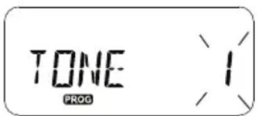
Press the and buttons to toggle through the Call Tones settings and select the desired call tone value (0, 1, 2, 3, 4, 5, or 6). Each time you select a different value, your radio sounds the selected call tone (except for value '0').
desired call tone value (0, 1, 2, 3, 4, 5, or 6). Each time you select a different value, your radio sounds the selected call tone (except for value '0').
Once you have selected the desired call tone, press the (Menu) button to save and proceed to the next step, or turn OFF the radio to exit without saving changes. Call Tones can also be configured using CPS.
You can enable the Channel Scanning Feature for a specific channel frequency for the radio in Scan List Menu. To enter the Scan Menu, press the (Menu) button until the radio displays the channel number, the ccom and blinks the current setting (YES' or NO') as follows:
You can enable the Channel Scanning Feature for a specific channel frequency for the radio in the Scan List Menu. To enter the Scan Menu, press the (Menu) button until the radio displays the channel number, the channel, and blinks the current setting (YES or NO) as follows:
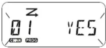
Press the and buttons to set SCAN to enable (YES) or disable (NO). Press SB1 or SB2 button to cycle through all the channels. Once you have selected the scan setting, press the (Menu) button to save and proceed to the next step, or turn OFF the radio to exit without saving changes. Scan List Menu can also be configured using CPS.
PROGRAMMING FEATURES
To easily program all the features in your radio, it is recommended to use the Customer Programming Software (CPS) and the programming cable.
CPS software download is available for free at www.motorolasolutions.com
To enter 'Programming Mode', press and hold the PTT Button and the SB1 Button simultaneously for 3 seconds, while turning ON the radio. An audible voice announces the Channel Number, indicating the radio has entered 'Programming Mode'. The radio LED blinks a green heartbeat.
When the radio is set to 'Programming Mode', the display shows and the current channel aliasing name blinks to indicate that you can rotate the Channel Selector Knob to select the channel you want to program.
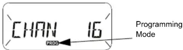
In 'Programming Mode', the radio is capable of setting values for each channel by toggling between the different programming modes available:
- Frequencies,
- CTCSS/DPL Codes (Interference Eliminator Code),
- Scramble, and
Scan
To move along the different 'Programming Selection Mode' without saving changes, short press the PTT Button or (Menu) Button. - To save changes, long press the PTT Button. The radio returns to 'Idle' Programming Mode. - When in 'Idle' Programming Mode, long press the PTT button to exit the 'Programming Mode'. - Whenever you wrap around to the beginning of
English
the 'Programming Mode' options, the radio automatically saves all changes made, even if you turn OFF the radio.
- Exit the 'Programming Mode' without saving changes (as long as you have not wrapped around to the beginning of the 'Programming Mode' options) by turning OFF the radio.
PROGRAMMING RX (RECEPTION) FREQUENCIES
Once you have chosen the channel you want to program, short press the PTT button or (Menu) button to scroll through the options until you reach 'Frequency Programming Mode'.
The radio display shows the frequency code as follows:
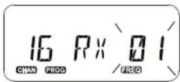
To program the desired frequency, use the A and buttons to navigate to the frequency code value you need. Long press the PTT button to exit and save, or short press the PTT button to move to the next programming feature without saving.
PROGRAMMING RX (RECEPTION) CODES (CTCSS/DPL)
Once you have chosen the channel you want to program, short press the PTT button or (Menu) button to scroll through the options until you reach the 'Code Programming Mode'.
The radio display shows the CTCSS/DPL code as follows:
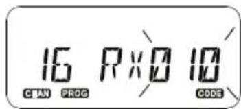
To program the desired code, use the and buttons until you get the CTCSS/DPL code
value you want to set up. Long press the PTT button to exit and save, or short press the PTT button to move to the next programming feature without saving.
PROGRAMMING SCRAMBLE
The scramble feature makes your transmissions sound garbled to anyone listening without the same scramble code. It does not guarantee confidentiality, but it adds an extra layer of privacy. Scramble mode is by default set to 'OFF'.
Once you have entered 'Programming Mode' and selected the channel in which you want to enable Scramble (scroll up or down through the programming modes by short pressing the PTT button or (Menu) button until the radio reaches the Scramble
Programming Mode.
The radio display shows the Scramble settings as follows:
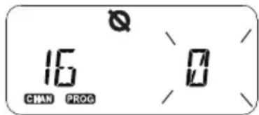
The current scramble value blinks. You can select the desired scramble value (0,1,2,3 or 4) by pressing the and buttons. Long press the PTT button to exit and save, or short press the PTT button to move to the next programming feature without saving.
Note: Scramble is disabled when the value is set to '0'.
SCAN
Scan allows you to monitor other channels to detect conversations. When the radio detects a transmission, it stops scanning and goes to the active channel. This allows you to listen and talk to people in that channel without having to change channel manually. If there is talking going on Channel 2 during this time, the radio stays on Channel 1 and you will not hear Channel 2. After talking has stopped in Channel 1, the radio waits for 5 seconds before resuming scan again.
- To start scanning, press the SB1 or SB2 button (programmed for scan). When the radio detects channel activity, it stops on that channel until activity on that channel ends. You can talk to the person(s) transmitting without having to switch channels by pressing the PTT button.
Note: Scan has to be programmed either to SB1 or SB2 button via CPS. SB2 is by default Scan/Nuisance Channel delete button. If Auto-Scan has been enabled for a particular
channel, do not press SB1 or SB2 (programmed for scan) to start scanning, as the radio does it automatically.
- To stop scanning, short press the SB1 or SB2 button (programmed for scan) again.
- By pressing the PTT button while the radio is scanning, the radio transmits on the channel which was previously selected before Scan is activated. If no transmission occurs within 5 seconds, scanning resumes.
- If you want to scan a channel without the Interference Eliminator Codes (CTCSS/DPL), set the code settings for the channels to '0' in the CTCSS/DPL Programming Selection Mode.
Note: Whenever the radio is set to Scan, the LED Indicator blinks a Red Heartbeat.
PROGRAMMING SCAN LIST
You can enable or disable the Channel Scanning feature for each channel in your radio. To do so, enter the 'Programming Mode' and select the channel you want to program. Scroll through the programming modes by short pressing the PTT button or (Menu) button until you reach the 'Scan Programming Mode'.
The radio display shows the Scan Programming Mode as follows:
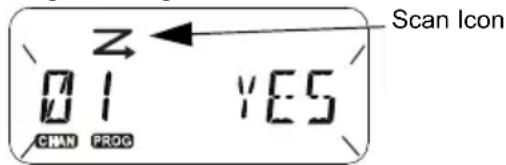
Both the channel number and current scan setting (YES = Enable or NO = Disable) blinks on the display, indicating you can choose your setting. To set the channel number, rotate the Channel Selector Knob until you reach the desired channel number.
To enable ('YES') or disable ('NO') the scan feature, press the end buttons. To configure the channel number, use the SB1 and SB2 buttons. Once you have set the values you need, long press the PTT button to exit and save, or short press the PTT button to move to the next programming feature without saving.
Note: If the Maximum Channel (MAX CHAN) setting in the radio is set to '1', the Scan Programming option is disabled and will not show on the radio display.
Editing Channel Alias Name
To edit a Channel Alias Name, turn ON the radio and press and hold the PTT button simultaneously with the button for 3 seconds. The radio generates a special beep upon entering the 'Channel Alias Mode'.
The radio display shows the current channel alias name and channel number blinking as follows:
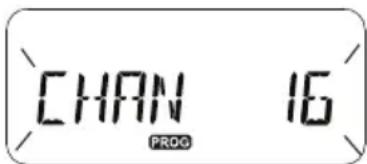
Choose the channel number you want to edit by rotating the Channel Selector Knob. Once you have selected the channel number, short
press the PTT button or (Menu) button to start editing the channel alias name.
- The character to be changed starts blinking. If it's a blank character, a cursor starts blinking.
- To change character, press the aD A B P buttons until the desired character is reached. To move to next character on the right, press the
(Menu) button. The character sequence is [A-Z], " (Blank Space), [0-9] and Special Characters. No lower case is allowed.
Long press the PTT button to save and go back to the 'Channel Alias Mode' to choose other channel to edit the alias name or turn OFF the radio to exit without saving the changes.
Note: If the channel alias name is left blank, long pressing the PTT button does not save or leave the alias name.
NUISANCE CHANNEL DELETE
Nuisance Channel Delete allows you to temporarily remove channels from the Scan List. This feature is useful when irrelevant conversations on a 'nuisance' channel ties up the radio's scanning feature.
To delete a channel from the Scan List:
- Start Scan mode by short pressing the SB2(*) button.
- Wait until the radio stops receiving on the channel you wish to eliminate. Long press the SB2 button to delete it. You cannot delete the channel with scan enabled (home channel).
- The channel will not be scanned again until you exit the Scan mode by short pressing the SB2 button again or by turning OFF the radio and back ON.
Note: (*) This assumes the SB2 button is not programmed for a different mode.
CUSTOMER PROGRAMMING SOFTWARE (CPS)
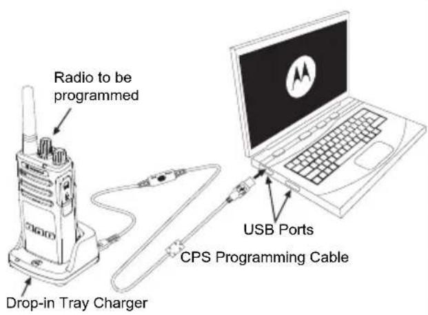
Figure 1: Setting up the radio to the CPS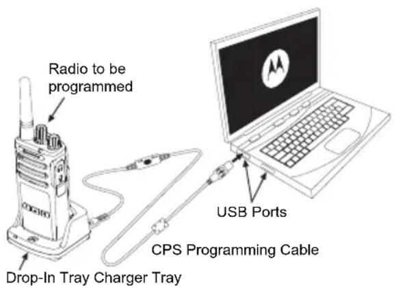
The easiest way to program or change features in your radio is by using the Customer Programming Software (CPS) and the CPS Programming Cable (*) . CPS Software is available for free as web based downloadable software at:
www.motorolasolutions.com
To program, connect the XT Series radio via the Drop-in Charger Tray and CPS Programming Cable as shown in Figure 1 on page 40. Toggle the cable switch of the CPS Programming Cable to 'CPS Mode'.
CPS allows you to program frequencies, PL/ DPL Codes as well as other features such as: Time-out Timer, Scan List, Call Tones, Scramble, Reverse Burst, etc. CPS is a very useful tool as it can also lock the Front-Panel Radio Programming or restrict any specific radio feature to be changed (to avoid accidentally erasing the preset radio values). It also provides security by giving the option to set up a password for profile radio's management. For more information, refer to Features Summary Chart Section at the end of the User Guide.
Note: (*) CPS Programming Cable P/N# HKKN4027_ is an accessory sold separately. Please contact your Motorola Solutions point of purchase for more information.
Time-Out Timer
Transmissions can be terminated when the PTT button is pressed by setting up a Time-Out Timer.
Reverse Burst
Reverse Burst eliminates unwanted noise (squelch tail) during loss of carrier detection. You can select values of either 180 or 240 to be compatible with other radios.
- The features described in previous pages are just some of the features CPS has. CPS offers more capabilities. For more information refer to the HELP file in the CPS.
- Some of the features available with the CPS software may vary depending on the radio model.
CLONING RADIOS
You can clone XT Series radio profiles from one Source radio to a Target radio by using any one of these 3 methods:
- Using a Multi Unit Charger (MUC-optional accessory),
- Using two Single Unit Chargers (SUC) and a Radio-to-Radio cloning cable (optional accessory),
- the CPS (free software download)
Cloning with a Multi-Unit Charger (MUC)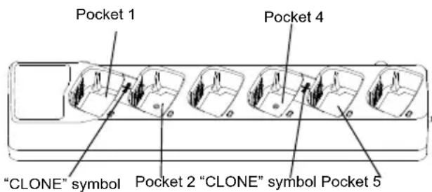
To clone radios using the MUC, there must be at least two radios:
- a Source radio (radio which profiles will be cloned or copied from) and
- a Target radio (the radio which profile will be cloned from the source radio.)
The Source radio has to be in Pocket 1 or 4 while the Target radio has to be in Pocket 2 or 5, matching in the MUCs pockets by pairs as follows:
1 and 2 or, 4 and 5.
When cloning, the MUC does not need to be plugged into a power source, but ALL radios require charged batteries.
- Turn ON the Target radio and place it into one of the MUC Target Pockets
- Power the Source radio following the sequence below:
- Long press the PTT button and SB2 simultaneously while turning the radio ON.
- Wait for 3 seconds before releasing the buttons until the audible tone "Cloning" is heard.
- Place the Source radio in the source pocket that pairs with the target pocket you chose in step 1. Press and release the SB1 button.
- After cloning is completed, the Source radio will announce either "successful" (cloning is successful) or "fail" (cloning has failed). If the Source radio is a display model, it will either show 'Pass' or 'Fail' on the display (a tone is heard within 5 seconds).
- Once you have completed the cloning process, turn the radios OFF and ON to exit the 'cloning' mode.
Further details on how to clone radios are explained in the Instructions Sheet provided with the MUC.
When ordering the MUC, refer to P/N# PMLN6385_.
Notes:
- If cloning fails, refer to "What To Do If Cloning Fails" on page 46.
- Paired Target radios and Source radios must be of the same band type in order for the cloning to run successfully.
- MUC pocket numbers should be read from left to right with the Motorola Solutions logo facing front.
- A radio programmed with the expanded frequencies (446.00625 MHz-446.19375 MHz) will not support cloning to legacy eight-frequency radios.
CPS and Cloning Cables (Optional Accessory)
- Both CPS and Cloning Cables are designed to work with either XT Series radios or XTNi Series radios. The cloning cable supports a mix of XT and XTNi series radios.
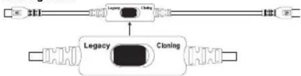
- The CPS cable programs XT series radios. Make sure the cable switch is in the "Flash" or "CPS" position. To program an XTNi radio with the CPS cable, ensure the cable switch is in the "CPS" position and the USB converter provided in the CPS cable kit is attached to the cable.
- The cloning cable allows you to clone:
- XT Series radios: Make sure the switch is in the "Cloning" or "Legacy" position. - XTNi Series radios: Make sure the switch is in the "Legacy" position with one USB converter on each end of the cloning cable. - XT Series and XTNi Series radios: Make sure the switch is in the "Legacy" position and use a USB converter to the XTNi Single-Unit Charger. The Cloning Cable Kit provides 1 USB converter.
CPS Cable
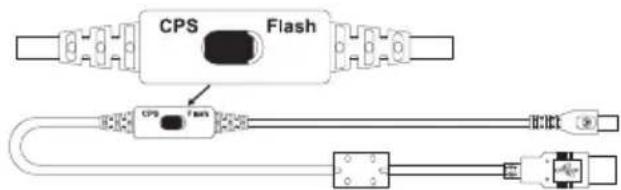
Cloning Cable
USB Converter

Cloning Radio using the Radio to Radio (R2R) Cloning Cable (Optional Accessory)
Operating Instructions
- Before starting the cloning process, make sure you have:
- A fully charged battery on each of the radios.
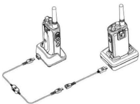
- Two Single-Unit Chargers (SUC), or 2 SUC for cloning RM Series radios, or 1 SUC for XT Series radio and 1 SUC for XTNi Series radio.
- Turn OFF the radios and,
- Unplug any cables (power supply or USB cables) from the SUCs.
- Plug one side of the cloning cable mini USB connector to the first SUC and the other end to the second SUC.
Note: During the cloning process, no power is being applied to the SUC. The batteries will not be charged. Only data communication is being established between the two radios.
- Turn ON the Target Radio and place it into one of the SUCs.
- For the Source Radio, power ON the radio with the following sequence:
- Long press the PTT button and the SB2 button simultaneously while turning the radio ON.
- Wait 3 seconds before releasing the buttons and you hear a distinctive audible tone saying the word "Cloning".
- Place the Source Radio in its SUC. Press and release the SB1 button.
- When the cloning is completed, the Source Radio audible voice announces either
"successful" (cloning is successful) or "fail" (cloning process has failed). If the Source Radio is a display model radio, it is either show 'Pass' or 'Fail' on the display (a tone is heard within 5 seconds).
- Once the cloning process is completed, turn the Radios OFF and ON again to exit "Clone" mode.
What To Do If Cloning Fails
The radio audible voice announces "Fail" indicating that the cloning process has failed. In the event that the cloning fails, perform each of the following steps before attempting to start cloning process again:
- Ensure that the batteries on both radios are fully charged.
- Check the cloning cable connection on both SUCs.
- Ensure that the battery is engaged properly on the radio.
- Ensure that there is no debris in the charging tray or on the radio contacts.
- Ensure that the Target radio is turned ON.
- Ensure that the Source radio is in cloning mode.
- Ensure that the two radios are both from the same frequency band, same region and have the same transmission power.
Note:
- This cloning cable is designed to operate only with compatible Motorola Solutions SUC PMLN6393_.
- A radio which is programmed with the expanded frequencies (446.00625 MHz-446.19375 MHz) will not support cloning to legacy eight frequency radios.
When ordering Cloning Cable, please refer to P/N# HKKN4028_. For more information about the accessories, refer to "Accessories" on page 62.
Cloning using the Customer Programming Software (CPS)
When cloning using this method, you need the CPS software, a Drop-In Tray Charger and the CPS Programming Cable.
To order the CPS Programming Cable, please refer to P/N# HKKN4028_.
Information on how to clone using the CPS is available either in:
- the CPS Help File -> Content and Index -> Cloning Radios, or
- in the CPS Programming Cable Accessory Leaflet.
TROUBLESHOOTING
| Symptom Try This... | |
| No Power | Recharge or replace the Li-1on battery. Extreme operating temperatures may affect battery life. Refer to “About the Li-Ion Battery” on page 13 |
| Hearing other noises or conversation on a channel | Confirm Interference Eliminator Code is set. Frequency or Interference Eliminator Code may be in use. Change settings: either change frequencies or codes on all radios. Make sure radio is at the right frequency and code when transmitting. Refer to “Talking and Monitoring” on page 23 |
| Message Scrambled | Scramble Code might be ON, and/or setting does not match the other radios' settings. |
| Audio quality not good enough | Radio settings might not be matching up correctly. Double check frequencies, codes and bandwidths to make sure they are identical in all radios |
| Limited talk range | Steel and/or concrete structures, heavy foliage, buildings or vehicles decrease range. Check for clear line of sight to improve transmission. Wearing radio close to body such as in a pocket or on a belt decreases range. Change location of radio. To increase range and coverage, you can reduce obstructions or increase power. UHF radios provides greater coverage in industrial and commercial buildings. Increasing power provides greater signal range and increased penetration through obstructions. Refer to “Talking and Monitoring” on page 23 |
| Message not transmitted or received | Make sure the PTT button is completely pressed when transmitting. Confirm that the radios have the same Channel, Frequency, Interference Eliminator Code and Scramble Code settings. Refer to “Talking and Monitoring” on page 23 for further information. Recharge, replace and/or reposition batteries. Refer to “About the Li-Ion Battery” on page 13. Obstructions and operating indoors, or in vehicles, may interfere. Change location. Refer to “Talking and Monitoring” on page 23. Verify that the radio is not in Scan. Refer to “Scan” on page 37 and “Nuisance Channel Delete” on page 40. |
| Heavy static or interference | Radios are too close; they must be at least five feet apart. Radios are too far apart or obstacles are interfering with transmission. Refer to “Talking and Monitoring” on page 23. |
| Low batteries | Recharge or replace Li-Ion battery. Extreme operating temperatures affect battery life. Refer to “About the Li-Ion Battery” on page 13. |
| Drop-in Charger LED light does not blink | Check that the radio/battery is properly inserted and check the battery/charger contacts to ensure that they are clean and charging pin is inserted correctly. Refer to “Charging The Battery” on page 16, “Drop-in Tray Charger LED Indicators” on page 18 and “Installing the Lithium-Ion (Li-Ion) Battery” on page 14. |
| Low battery indicator is blinking although new batteries are inserted | Refer to “Installing the Lithium-Ion (Li-Ion) Battery” on page 14, and “About the Li-Ion Battery” on page 13. |
| Cannot activate VOX | VOX feature might be set to OFF.Use the CPS to ensure that the VOX Sensitivity level is not set to ‘0’.Accessory not working or not compatible.Refer to “Hands-Free Use/VOX” on page 27. |
| Battery does not chargealthough it has been placed inthe drop-in charger for a while | Check drop-in tray charger is properly connected and correspond to acomppatible power supply.Refer to “Charging with the Drop-in Tray Single Unit Charger (SUC)” onpage 16 and “Charging A Stand-Alone Battery” on page 17CHECK the charger's LEDs indicators to see if the battery has a problem. Referto “Drop-in Tray Charger LED Indicators” on page 18. |
Note: Whenever a feature in the radio seems to not correspond to the default or preprogrammed values, check to see if the radio has been programmed using the CPS with a customized profile.
USE AND CARE
Use a soft damp cloth to clean the exterior
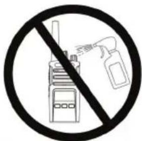
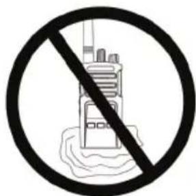
Do not immerse in water. Do not use alcohol or cleaning solutions.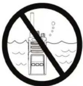
If the radio is submerged in water...
Turn radio OFF and remove batteries.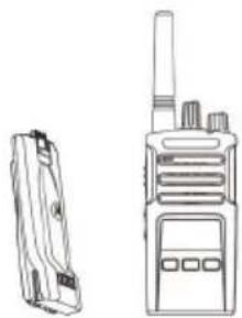
Dry with a soft cloth. Do not use radio until completely dry.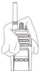
FREQUENCY AND CODE CHARTS
The charts in this section provide frequency and code information. These charts are useful when using the Motorola Solutions XT Series two-way radios with other business radios. Most of the frequency positions are the same as the XTNi Series frequency positions.
Default Channel Frequency and Interference Eliminator Code
| Channel # Frequency (MHz) Code Bandwidth C | ||
| 1 446.00 | 625 67.0 Hz 12.5 kHz | |
| 2 446.01 | 875 67.0 Hz 12.5 kHz | |
| 3 446.03 | 125 67.0 Hz 12.5 kHz | |
| 4 446.04 | 875 67.0 Hz 12.5 kHz | |
| 5 446.05 | 625 67.0 Hz 12.5 kHz | |
| 6 446.06 | 875 67.0 Hz 12.5 kHz | |
| 7 446.08 | 125 67.0 Hz 12.5 kHz | |
| 8 446.09 | 875 67.0 Hz 12.5 kHz | |
Note: Code 754 corresponds to DPL 121.
| nnel # | Frequency (MHz) | Code Bandwidth |
| 9 | 446.00625 754 12.5 kHz | |
| 10 | 446.01875 754 12.5 kHz | |
| 11 | 446.03125 754 12.5 kHz | |
| 12 | 446.04375 754 12.5 kHz | |
| 13 | 446.05625 754 12.5 kHz | |
| 14 | 446.06875 754 12.5 kHz | |
| 15 | 446.08125 754 12.5 kHz | |
| 16 | 446.09375 754 12.5 kHz |
XT460 Full Frequency List
| 446.00625 446.10625 | |
| 446.01875 446.11875 | |
| 446.03125 446.13125 | |
| 446.04375 446.14375 | |
| 446.05625 446.15625 | |
| 446.06875 446.16875 | |
| 446.08125 446.18125 | |
| 446.09375 446.19375 |
Warning: Only 446.0-446.1 MHz analogue frequencies are available by default. 446.1-446.2 MHz analogue frequencies should only be used in countries where these frequencies are allowed by government authorities. 446.1-446.2 MHz analogue frequencies are not allowed in Russia.
CTCSS AND PL/DPL CODES
CTCSS Codes
| CTCSS Hz | CTCSS Hz |
| 1 67.0 | 14 107.2 27 167.9 |
| 2 71.9 | 15 110.9 28 173.8 |
| 3 74.4 | 16 114.8 29 179.9 |
| 4 77.0 | 17 118.8 30 186.2 |
| 5 79.7 | 18 123 31 192.8 |
| 6 82.5 | 19 127.3 32 203.5 |
| 7 85.4 | 20 131.8 33 210.7 |
| 8 88.5 | 21 136.5 34 218.1 |
| 9 91.5 | 22 141.3 35 225.7 |
| 10 94.8 | 23 146.2 36 233.6 |
| 11 | |
| 12 100.0 | 25 156.7 38 250.3 |
| 13 103.5 | 26 162.2 |
| SS Hz | |
| 7 241.8 | |
| 122 (*) | 69.3 |
Note: (*) New CTCSS code.
PL/DPL Codes
| DPL Code DPL Code | ||||
| 39 23 | 55 116 71 243 | |||
| 40 25 | 56 125 72 244 | |||
| 41 26 | 57 131 73 245 | |||
| 42 31 | 58 132 74 251 | |||
| 43 32 | 59 134 75 261 | |||
| 44 43 | 60 143 76 263 | |||
| 45 47 | 61 152 77 265 | |||
| 46 51 | 62 155 78 271 | |||
| 47 54 | 63 156 79 306 | |||
| 48 65 | 64 162 80 311 | |||
| 49 71 | 65 165 81 315 | |||
| 50 72 | 66 172 82 331 | |||
| 51 73 | 67 174 83 343 | |||
| 52 74 | 68 205 84 346 | |||
| 53 114 | 69 223 85 351 | |||
| 54 115 | 70 226 86 364 | |||
| ode | |
English
PL/DPL Codes (Continued)
| DPL Code | DPL Code | ||
| 87 365 | 104 565 121 754 | ||
| 88 371 | 105 606 123 645 | ||
| 89 411 | 106 612 12 Customized PL | ||
| 90 412 | 107 624 125 Customized PL | ||
| 91 413 | 108 627 126 Customized PL | ||
| 92 423 | 109 631 127 Customized PL | ||
| 93 431 | 110 632 128 Customized PL | ||
| 94 432 | 111 654 129 Customized PL | ||
| 95 445 | 112 662 130 Inverted DPL | 39 | |
| 96 464 | 113 664 131 Inverted DPL | 40 | |
| 97 465 | 114 703 132 Inverted DPL | 41 | |
| 98 466 | 115 712 133 Inverted DPL | 42 | |
| 99 503 | 116 723 134 Inverted DPL | 43 | |
| 100 506 | 117 731 135 Inverted DPL | 44 | |
| 101 516 | 118 732 136 Inverted DPL | 45 | |
| 102 532 | 119 734 137 Inverted DPL | 46 | |
| 103 546 | 120 743 138 Inverted DPL | 47 | |
| DPL | Code |
| DPL Code DPL Code | |
| 139 | Inverted DPL 48 |
| 140 | Inverted DPL 49 |
| 141 | Inverted DPL 50 |
| 142 | Inverted DPL 51 |
| 143 | Inverted DPL 52 |
| 144 | Inverted DPL 53 |
| 145 | Inverted DPL 54 |
| 146 | Inverted DPL 55 |
| 147 | Inverted DPL 56 |
| 148 | Inverted DPL 57 |
| 149 | Inverted DPL 58 |
| 150 | Inverted DPL 59 |
| 151 | Inverted DPL 60 |
| 152 | Inverted DPL 61 |
| 153 | Inverted DPL 62 |
| 154 | Inverted DPL 63 |
| 155 | Inverted DPL 64 |
| ode | |
| 156 | Inverted DPL 65 |
| 157 | Inverted DPL 66 |
| 158 | Inverted DPL 67 |
| 159 | Inverted DPL 68 |
| 160 | Inverted DPL 69 |
| 161 | Inverted DPL 70 |
| 162 | Inverted DPL 71 |
| 163 | Inverted DPL 72 |
| 164 | Inverted DPL 73 |
| 165 | Inverted DPL 74 |
| 166 | Inverted DPL 75 |
| 167 | Inverted DPL 76 |
| 168 | Inverted DPL 77 |
| 169 | Inverted DPL 78 |
| 170 | Inverted DPL 79 |
| 171 | Inverted DPL 80 |
| 172 | Inverted DPL 81 |
| 173 | Inverted DPL 82 |
| 174 | Inverted DPL 83 |
| 175 | Inverted DPL 84 |
| 176 | Inverted DPL 85 |
| 177 | Inverted DPL 86 |
| 178 | Inverted DPL 87 |
| 179 | Inverted DPL 88 |
| 180 | Inverted DPL 89 |
| 181 | Inverted DPL 90 |
| 182 | Inverted DPL 91 |
| 183 | Inverted DPL 92 |
| 184 | Inverted DPL 93 |
| 185 | Inverted DPL 94 |
| 186 | Inverted DPL 95 |
| 187 | Inverted DPL 96 |
| 188 | Inverted DPL 97 |
| 189 | Inverted DPL 98 |
| DPL | Code |
| 190 | Inverted DPL 99 |
| 191 | Inverted DPL 100 |
| 192 | Inverted DPL 101 |
| 193 | Inverted DPL 102 |
| 194 | Inverted DPL 103 |
| 195 | Inverted DPL 104 |
| 196 | Inverted DPL 105 206 |
| 197 | Inverted DPL 106 |
| 198 | Inverted DPL 107 208 |
| 199 | Inverted DPL 108 |
| DPL Code | |
| 200 | Inverted DPL 109 |
| 201 | Inverted DPL 110 |
| 202 | Inverted DPL 111 |
| 203 | Inverted DPL 112 |
| 204 | Inverted DPL 113 |
| 205 | Inverted DPL 114 |
| ed DPL | 115 216 Customize |
| 207 | Inverted DPL 116 |
| ed DPL | 117 218 Customize |
| 209 | Inverted DPL 118 |
| DPL | Code |
| 210 | Inverted DPL 119 |
| 211 | Inverted DPL 120 |
| 212 | Inverted DPL 121 |
| 213 | Inverted DPL 123 |
| 214 | Customized DPL |
| 215 | Customized DPL |
| 217 | Customized DPL |
| 219 | Customized DPL |
MOTOROLA SOLUTIONS LIMITED WARRANTY
WARRANTY INFORMATION
The authorised Motorola Solutions dealer or retailer where you purchased your Motorola Solutions two-way radio and/or original accessories will honour a warranty claim and/or provide warranty service. Please return your radio to your dealer or retailer to claim your warranty service. Do not return your radio to Motorola Solutions. To be eligible to receive warranty service, you must present your receipt of purchase or a comparable substitute proof of purchase bearing the date of purchase. The two-way radio should also clearly display the serial number. The warranty will not apply if the type or serial numbers on the product have been altered, deleted, removed or made illegible.
WHAT IS NOT COVERED BY THE WARRANTY
- Defects or damage resulting from use of the Product in other than its normal and customary manner or by not following the instructions in this user guide.
- Defects or damage from misuse, accident or neglect.
- Defects or damage from improper testing, operation, maintenance, adjustment or any alteration or modification of any kind.
- Breakage or damage to aerials unless caused directly by defects in material or workmanship.
- Products disassembled or repaired in such a manner as to adversely affect performance or prevent adequate inspection and testing to verify any warranty claim.
- Defects or damage due to moisture, liquid or spills.
- All plastic surfaces and all other externally exposed parts that are scratched or damaged due to normal use.
- Products rented on a temporary basis.
- Periodic maintenance and repair or replacement of parts due to normal usage, wear and tear.
ACCESSORIES
AUDIO ACCESSORIES
| Part No. Description | |
| HKLN4599_ | D-Style Earpiece with Clip PTT Mic |
| HKLN4601_ | Surveillance Earpiece with Clip PTT Mic |
| HKLN4604_ | Swivel Earpiece with Clip PTT Mic |
| HKLN4605_Earbud with Clip PTT Mic | |
| HKLN4606_Remote Speaker Mic | |
BATTERY
| Part No. Description | |
| PMNN4434_Standard Li-Ion Battery | |
| PMNN4453_High Capacity Li-Ion Battery |
CABLES
| Part No. Description | |
| HKKN4028_Radio to Radio Cloning Cable | |
| HKKN4027_CPS Programming Cable |
CHARGERS
| Part No. Description | |
| PMLN6385_ | Standard Drop-In Tray Multi-Unit Charger UK/EU Kit |
| PMLN6393_ | Standard Drop-In Tray Single Unit Charger INT UK/EU |
CARRY ACCESSORIES
Part No. Description
HKLN4510_Swivel Holster
Note: Certain accessories may or may not be available at the time of purchase. Please contact your Motorola Point of Purchase or visit www.motorolasolutions.com for latest information on accessories availability and new accessories models.
MOTOROLA, MOTO, MOTOROLA SOLUTIONS and the Stylized M logo are trademarks or registered trademarks of Motorola Trademark Holdings, LLC and are used under license. All other trademarks are the property of their respective owners.
© 2013 and 2018 Motorola Solutions, Inc. All rights reserved.
CPS (Customer Programming Software) 40 Timer for timeout 41 Reverse Burst 41
ADJUSTING THE AUDIO LEVEL
CPS (CUSTOMER PROGRAMMING SOFTWARE)
WHAT IS NOT COVERED BY THE WARRANTY
HKLN4510_Rotating housing
Reading the display. 22
READING THE DISPLAY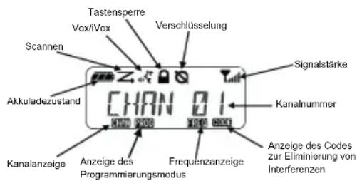
HKLN4510_Rotating housing
PTT button (Push-to-Talk)
RECEIVING A CALL
RX (RECEIVE) PROGRAMMING CODES (CTCSS/DPL)
PROGRAMMING SOFTWARE (CUSTOMER PROGRAMMING SOFTWARE, CPS)
Figure 1: Radio configuration in CPS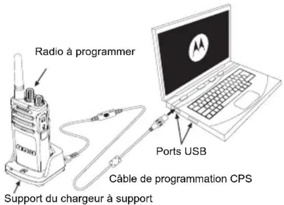
PL/DPL codes (Continued)
WARRANTY INFORMATION
TRANSPORT ACCESSORIES
Legal note on open source software:
CPS (Customer Programming Software) 42
Timeout timer 43
Reverse burst 43
(Customer Programming Software) 49
Troubleshooting 50
PTT (Push-to-Talk) button
CPS (CUSTOMER PROGRAMMING SOFTWARE)
| N. canale | Frequenza (MHz) | Codice | Larghezza di banda |
| 1 | 446,00625 | 67,0 Hz | 12,5 kHz |
| 2 | 446,01875 | 67,0 Hz | 12,5 kHz |
| 3 | 446,03125 | 67,0 Hz | 12,5 kHz |
| 4 | 446,04375 | 67,0 Hz | 12,5 kHz |
| 5 | 446,05625 | 67,0 Hz | 12,5 kHz |
| 6 | 446,06875 | 67,0 Hz | 12,5 kHz |
| 7 | 446,08125 | 67,0 Hz | 12,5 kHz |
| 8 | 446,09375 | 67,0 Hz | 12,5 kHz |
| N. canale | Frequenza (MHz) | Codice | Larghezza di banda |
| 9 | 446,00625 | 754 | 12,5 kHz |
| 10 | 446,01875 | 754 | 12,5 kHz |
| 11 | 446,03125 | 754 | 12,5 kHz |
| 12 | 445,04375 | 754 | 12,5 kHz |
| 13 | 446,05625 | 754 | 12,5 kHz |
| 14 | 446,06875 | 754 | 12,5 kHz |
| 15 | 446,08125 | 754 | 12,5 kHz |
| 16 | 446,09375 | 754 | 12,5 kHz |
Programming Software (CPS -
Customer Programming Software). . . . .48
Troubleshooting 49
Push-to-Talk (PTT) button
PROGRAMMING RX (RECEIVE) CODES (CTCSS/DPL)
| 446.00625 446.10625 | |
| 446.01875 446.11875 | |
| 446.03125 446.13125 | |
| 446.04375 446.14375 | |
| 446.05625 446.15625 | |
| 446.06875 446.16875 | |
| 446.08125 446.18125 | |
| 446.09375 446.19375 |
Nuisance Channel Delete. 39
Customer Programming Software (CPS) 39 Timeout timer 40 Squelch 40
Clone radios 41 Cloning with a multi-unit charger (MUC) 41
PRODUCT SAFETY AND RF EXPOSURE COMPLIANCE
Warning
Before using this product, you must read the user manual and the RF energy information found in the product safety and RF exposure booklet that came with the radio.
NOTE!
Note: Buttons SB1 and SB2 are
PTT button (Push-to-Talk, press to talk)
| Kanalnr. | Frekvens (MHz) | Kode Båndbredde Ka |
| 1 446,0 | 0625 67,0 Hz | 12,5 kHz |
| 2 446,0 | 1875 67,0 Hz | 12,5 kHz |
| 3 446,0 | 3125 67,0 Hz | 12,5 kHz |
| 4 446,0 | 4375 67,0 Hz | 12,5 kHz |
| 5 446,0 | 5625 67,0 Hz | 12,5 kHz |
| 6 446,0 | 6875 67,0 Hz | 12,5 kHz |
| 7 446,0 | 8125 67,0 Hz | 12,5 kHz |
| 8 446,0 | 9375 67,0 Hz | 12,5 kHz |
| Inr. | Frekvens (MHz) | Kode Båndbredde |
| 9 | 446,00625 754 12,5 kHz | |
| 10 | 446,01875 754 12,5 kHz | |
| 11 | 446,03125 754 12,5 kHz | |
| 12 | 445,04375 754 12,5 kHz | |
| 13 | 446,05625 754 12,5 kHz | |
| 14 | 446,06875 754 12,5 kHz | |
| 15 | 446,08125 754 12,5 kHz | |
| 16 | 446,09375 754 12,5 kHz |
Note: Code 754 corresponds to DPL 121
Full frequency list for XT460
| 446,00625 446,10625 | |
| 446,01875 446,11875 | |
| 446,03125 446,13125 | |
| 446,04375 446,14375 | |
| 446,05625 446,15625 | |
| 446,06875 446,16875 | |
| 446,08125 446,18125 | |
| 446,09375 446,19375 |
Warning: Only the analog frequencies 446.0-446.1 MHz are available by default. The analog frequencies 446.1-446.2 MHz should only be used in countries where these frequencies are permitted by the authorities. The analog frequencies 446.1-446.2 MHz are not permitted in Russia.
CTCSS AND PL/DPL CODES
CTCSS codes
| CTCSS Hz | CTCSS Hz |
| 1 67,0 | 14 107,2 27 167,9 |
| 2 71,9 | 15 110,928 173,8 |
| 3 74,4 | 16 114,8 29 179,9 |
| 4 77,0 | 17 118,830 186,2 |
| 5 79,7 | 18 123 31 192,8 |
| 6 82,5 | 19 127,3 32 203,5 |
| 7 85,4 | 20 131,8 33 210,7 |
| 8 88,5 | 21 136,5 34 218,1 |
| 9 91,5 | 22 141,3 35 225,7 |
| 10 94,8 | 23 146,2 36 233,6 |
| 11 97,4 | 24 151,4 37 241,8 |
| 12 100,0 | 25 156,7 38 250,3 |
| 13 103,5 | 26 162,2 |
| SS Hz | |
| 122 (*) | 69,3 |
Note: (*) new CTCSS code.
PL/DPL codes
| DPL Kode | DPL | Kode | D |
| 39 23 | 55 | 116 | 71 243 |
| 40 25 | 56 | 125 | 72 244 |
| 41 26 | 57 | 131 | 73 245 |
| 42 31 | 58 | 132 | 74 251 |
| 43 32 | 59 | 134 | 75 261 |
| 44 43 | 60 | 143 | 76 263 |
| 45 47 | 61 | 152 | 77 265 |
| 46 51 | 62 | 155 | 78 271 |
| 47 54 | 63 | 156 | 79 306 |
| 48 65 | 64 | 162 | 80 311 |
| 49 71 | 65 | 165 | 81 315 |
| 50 72 | 66 | 172 | 82 331 |
| 51 73 | 67 | 174 | 83 343 |
| 52 74 | 68 | 205 | 84 346 |
| 53 114 | 69 | 223 | 85 351 |
| 54 115 | 70 | 226 | 86 364 |
| de | |
PL/DPL codes (cont.)
| DPL | Kode | DPL | Kode |
| 87 365 | 104 565 121 754 | ||
| 88 371 | 105 606 123 645 | ||
| 89 411 | 106 6 | 12 124 Tilpasset PL | |
| 90 412 | 107 624 125 Tilpasset PL | ||
| 91 413 | 108 627 126 Tilpasset PL | ||
| 92 423 | 109 631 127 Tilpasset PL | ||
| 93 431 | 110 632 128 Tilpasset PL | ||
| 94 432 | 111 654 129 Tilpasset PL | ||
| 95 445 | 112 662 130 Invertert DPL | 39 | |
| 96 464 | 113 664 131 Invertert DPL | 40 | |
| 97 465 | 114 703 132 Invertert DPL | 41 | |
| 98 466 | 115 712 133 Invertert DPL | 42 | |
| 99 503 | 116 723 134 Invertert DPL | 43 | |
| 100 | 506 | 117 | 731 |
| 101 | 516 | 118 | 732 |
| 102 | 532 | 119 | 734 |
| 103 546 | 120 743 138 Invertert DPL | 47 |
PL/DPL codes (cont.)
| DPL Kode DPL Kode D | |
| 139 | Invertert DPL 48 |
| 140 | Invertert DPL 49 |
| 141 | Invertert DPL 50 |
| 142 | Invertert DPL 51 |
| 143 | Invertert DPL 52 |
| 144 | Invertert DPL 53 |
| 145 | Invertert DPL 54 |
| 146 | Invertert DPL 55 |
| 147 | Invertert DPL 56 |
| 148 | Invertert DPL 57 |
| 149 | Invertert DPL 58 |
| 150 | Invertert DPL 59 |
| 151 | Invertert DPL 60 |
| 152 | Invertert DPL 61 |
| 153 | Invertert DPL 62 |
| 154 | Invertert DPL 63 |
| 155 | Invertert DPL 64 |
| de | |
| 156 | Invertert DPL 65 |
| 157 | Invertert DPL 66 |
| 158 | Invertert DPL 67 |
| 159 | Invertert DPL 68 |
| 160 | Invertert DPL 69 |
| 161 | Invertert DPL 70 |
| 162 | Invertert DPL 71 |
| 163 | Invertert DPL 72 |
| 164 | Invertert DPL 73 |
| 165 | Invertert DPL 74 |
| 166 | Invertert DPL 75 |
| 167 | Invertert DPL 76 |
| 168 | Invertert DPL 77 |
| 169 | Invertert DPL 78 |
| 170 | Invertert DPL 79 |
| 171 | Invertert DPL 80 |
| 172 | Invertert DPL 81 |
| 173 | Invertert DPL 82 |
| 174 | Invertert DPL 83 |
| 175 | Invertert DPL 84 |
| 176 | Invertert DPL 85 |
| 177 | Invertert DPL 86 |
| 178 | Invertert DPL 87 |
| 179 | Invertert DPL 88 |
| 180 | Invertert DPL 89 |
| 181 | Invertert DPL 90 |
| 182 | Invertert DPL 91 |
| 183 | Invertert DPL 92 |
| 184 | Invertert DPL 93 |
| 185 | Invertert DPL 94 |
| 186 | Invertert DPL 95 |
| 187 | Invertert DPL 96 |
| 188 | Invertert DPL 97 |
| 189 | Invertert DPL 98 |
PL/DPL codes (cont.)
| DPL | Kode |
| 190 | Invertert DPL 99 |
| 191 | Invertert DPL 100 |
| 192 | Invertert DPL 101 |
| 193 | Invertert DPL 102 |
| 194 | Invertert DPL 103 |
| 195 | Invertert DPL 104 |
| 196 | Invertert DPL 105 206 |
| 197 | Invertert DPL 106 |
| 198 | Invertert DPL 107 208 |
| 199 | Invertert DPL 108 |
| DPL | Kode |
| 200 | Invertert DPL 109 |
| 201 | Invertert DPL 110 |
| 202 | Invertert DPL 111 |
| 203 | Invertert DPL 112 |
| 204 | Invertert DPL 113 |
| 205 | Invertert DPL 114 |
| rt DPL 1 | 15 216 Tilpasset DP |
| 207 | Invertert DPL 116 |
| rt DPL 1 | 17 218 Tilpasset DP |
| 209 | Invertert DPL 118 |
| DPL | Kode |
| 210 | Invertert DPL 119 |
| 211 | Invertert DPL 120 |
| 212 | Invertert DPL 121 |
| 213 | Invertert DPL 123 |
| 214 | Tilpasset DPL |
| 215 | Tilpasset DPL |
| 217 | Tilpasset DPL |
| 219 | Tilpasset DPL |
LIMITED WARRANTY FOR MOTOROLA SOLUTIONS
WARRANTY INFORMATION
The authorized Motorola Solutions dealer or retailer from whom you purchased your Motorola Solutions two-way radio and/or original accessories will honor warranty claims and/or provide warranty service. Return the radio to the dealer or retailer to request warranty service. Do not return the radio to Motorola Solutions. To be eligible for warranty service, you must show proof of purchase, such as a receipt or other equivalent purchase proof marked with the purchase date. The serial number on the two-way radio must also be clearly visible. The warranty will not apply if the type or serial number on the product has been altered, deleted, removed, or made illegible.
WHAT THE WARRANTY DOES NOT COVER
HKLN4510_Durable holster
Note: Some accessories may or may not be
Batteries and chargers 13
Push-to-Talk (PTT) button
Open Source Software Legal Notices:
PROGRAM CODES (CTCSS/DPL) RX (RECEPTION)
The URLs including a few names of the companies mentioned in the text.
© 2013 and 2018 Motorola Solutions, Inc.
Channel selector knob 10
LED indicator 10
Front panel .10
Side panels 11
Lithium-ion (Li-Ion) batteries . . . 11
Batteries and charging devices. 13
Battery charging characteristics. 13
Lithium-ion batteries. 13
Installing the lithium-ion battery 14
Removing the lithium-ion battery 15
Power supply and charging device with stand 15
Charger. 16
Charging the battery 17
Charging with a single charging device with stand 17
Charging device with stand LED indicators .19
Battery charge indicator .20
Approximate charging time 21
Operating instructions 24
Turning the radio station on and off 24
Volume adjustment 24
Data on the display 25
Channel selection 25
Call monitoring 25
COPYRIGHT FOR COMPUTER SOFTWARE
The products described in this manual may contain copyrighted computer programs of Motorola Solutions, stored in semiconductor memories or other media. The laws of the USA and some other countries provide certain exclusive rights to Motorola Solutions with respect to copyrighted computer programs, including, in particular, the right to copy and reproduce in any form copyrighted computer programs. In connection with this, no computer programs of Motorola Solutions contained
in Motorola Solutions products described in this manual may be copied, reproduced, modified, subjected to engineering analysis for the creation of analogues or distributed in any way whatsoever without the prior written permission of Motorola Solutions.
Moreover, the purchase of Motorola Solutions products will not result, directly, indirectly, procedurally or in any other manner, in the transfer of licenses for copyrights, patents or patented applications of Motorola Solutions, except for the usual non-exclusive license for use that arises by law upon the sale of the product.
SAFETY
PRODUCT SAFETY
AND
COMPLIANCE
EXPOSURE
RADIO FREQUENCY RADIATION
Warning!
Before using this product, read the operating instructions and safety instructions for the product and the requirements for exposure to radio frequency radiation, provided by the radio station in which the information about the radio frequency radiation is contained.
Warning!
This radio is intended for professional use and complies with the FCC/ICNIRP requirements regarding exposure to emitted radio frequency energy.
For a list of Motorola Solutions approved antennas, batteries, and other accessories, see the website:
www.motorolasolutions.com
SAFETY INFORMATION FOR HANDLING BATTERIES AND CHARGING DEVICES
This document contains important instructions for safe operation.
Read these instructions carefully and keep them for future reference.
Before using the battery charger, read all instructions and warnings provided on
1. To reduce the risk of injury, use the charger only for charging Motorola Solutions approved batteries. Charging other types of batteries may cause an explosion and, as a result, injury or material damage. 2. Use of accessories not recommended by Motorola Solutions may cause fire, electric shock, or injury. 3. To reduce the risk of electric shock from the plug and cable, disconnect the charger from the electrical outlet by holding the plug, not the cable.
the charger,
the battery, and the radio in which the battery is installed.
Russian
4. Use extension cables only when absolutely necessary. Using an extension cable with unacceptable parameters can cause fire or electric shock. If it is necessary to use an extension cable, make sure that a cable of the appropriate size is used. If the cable length does not exceed 30.48 m, a cable of size >1 mm should be used, and for a cable length up to 45.72 m, a cable of size >1.5 mm should be used. 5. To reduce the risk of fire, electric shock, or injury, do not use the charging device if it has any faults or damage. Take it to a qualified Motorola Solutions service representative.
- Do not disassemble the charging device: it is not repairable, and spare parts are not available. Disassembling the charging device can lead to electric shock or fire. 7. To reduce the risk of electric shock, unplug the device before performing any maintenance or cleaning.
SAFETY INSTRUCTIONS
- Turn off the radio while charging the battery. The charging device is not suitable for outdoor use. Use it only indoors with low humidity. - Connect this device only to a properly fused power supply with the appropriate voltage (its value is indicated on the housing). - Unplug the charging device by removing the power plug. - The outlet to which this equipment is connected must be located near the device, and free access to it must be ensured.
Replacement of fuses in the device must be done according to the type and value specified in the device instructions. - The maximum ambient temperature around the power supply must not exceed 40°C. - The output power of the power supply must not exceed the values indicated on the label located on the lower part of the charging device. - Check the placement of the power supply: it must be positioned so that you cannot step on it, trip over it, and so that it is not exposed to moisture or other mechanical damage.
RADIO OVERVIEW
EXTERNAL CONTROLS
Volume Knob / Power Switch
Used to turn the radio on or off and to adjust the volume.
Channel Selector Knob
Used to switch between different radio channels.
Contains the model name of the radio.
Microphone
When sending a message, speak clearly and distinctly into the microphone.
Antenna
The battery is not removable.
LED indicator
Used to indicate the battery status, power on, call information, and scanning status.
Buttons on the front panel
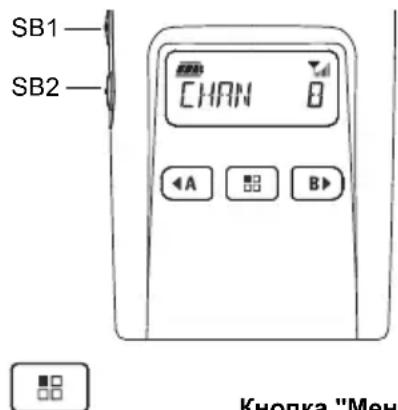
Provide access to functions and menus, as the level of I/O and I/O etc. In addition, when in programming mode, it allows navigation between all functions.
Programmable button
Allows selecting the level or options for switching between menu functions. By default, it is set to program the call signal.
Programmable button
Allows selecting the level or options for switching between menu functions. By default, it is set to backlight mode.
Note: The buttons can be programmed to perform functions. Examples of functions: "Scrambling", "Scan/Delete channel with interference", "Monitoring" and "Call signals". For more information on programming these buttons, see "User Programming (CPS)" on page 45.
Side buttons
PTT button (Push-To-Talk)
- Press and hold the PTT button to talk, release it to listen.
Side button 1 (SB1)
Side button 1 is a general button that can be configured using User Programming (CPS). By default, the SB1 button is set to the "Monitoring" function.
Bokovar KhoIIka 2 (SB2)
The SB2 button is a general button that can be configured with CPS. By default, the SB2 button is set to the function "Scan/Delete channel".
Table 3: Battery indicator LED
The sensitivity of accessories for the microphone of the radio station can be changed depending on the operating conditions of the device. The sensitivity of VOX can be programmed with CPS or the "Menu" button.
By default, the VOX sensitivity level is 3. You can set any of the VOX sensitivity levels listed in the list below.
1 = High voice input level triggers transmission - 2 = Medium sensitivity level - 3 = Low voice input level triggers transmission
Microphone gain
The microphone sensitivity of the radio station can be changed depending on the needs of users or the operating conditions of the device.
This function can be configured with the "Menu" button without using CPS. By default, the microphone is set to level 2 (medium gain).
"Hands free" mode without using accessories (VOX)
- To activate VOX, press the PTT button when the radio is turned on. The VOX indicator lights up. VOX can be temporarily disabled by pressing the PTT button.
- A short press on the PTT button activates VOX again.
Note.
There is a short delay between the moment the user starts speaking and the moment the radio station starts transmitting. For detailed information about VOX/VOX sensitivity, see "VOX/VOX sensitivity (Menu)" on page 34.
Turning on and off voice prompts in user mode
Short press of the SB1 button switches the radio on and off, and enables or disables voice announcements (voice announcements are enabled by default).
Tonal signal for power on
To enable or disable the tonal signal for power on, simultaneously press the SB1 and SB2 buttons and hold them for 2-3 seconds while turning on the radio, until you hear a series of short beeps and the programmed voice announcement about power on.
Reset to factory settings
This function restores all original factory settings of the radio. To reset the settings, simultaneously press the PTT, SB1, and SB2 buttons while turning on the radio and hold them until you hear a high-pitched beep.
Keypad beeps
To disable or enable keypad beeps, press the SB2 button while the radio is on (a beep will sound).
Keypad lock
You can lock the radio keypad to prevent accidental changes to settings. To lock the keypad, press and hold the "Menu" button for 4 seconds.
Microphone gain menu
The microphone sensitivity of the radio can be adjusted according to user needs or device operating conditions.
Press and hold the "Menu" button until "MIC" and "VOX" appear on the radio display, and the current microphone gain level starts flashing:
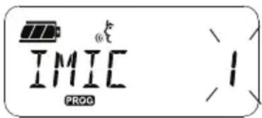
Press the buttons to select the microphone gain setting:
·1 = Low gain level -2 = Medium gain level -3 = High gain level
After selecting the desired microphone gain level, press the "Menu" button to save and proceed to the next step, or turn off the radio to exit without saving changes. Microphone gain can also be adjusted via CPS.
The gain level of the additional microphone
The gain level of the additional microphone can be adjusted in the additional microphone gain menu. Press and hold the ("MENU") button until "MIC" and the VOX icon appear on the display, and the current gain level of the additional microphone starts flashing:
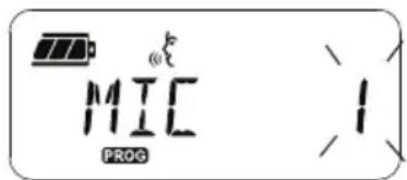
Press the gain adjustment selection button for the additional microphone and select the desired level
-1=Low gain level -2=Medium gain level -3=High gain level
After selecting the desired gain level for the additional microphone, press the ("MENU") button to save and proceed to the next step, or turn off the transceiver to save and exit. The gain of the additional microphone can also be adjusted via CPS.
Note: If the VOX and iVOX functions are activated, the MIC and iMIC parameters cannot be adjusted during use of the NX460 transceiver, because the VOX and iVOX functions automatically set a high gain level for the microphone.
Call signals
The channel frequency is in the menu
Scan list. To enter the menu
scanning, press and hold
the ("MENU") button until the display
shows the channel number
The tuning knob
(YES or NO) will start flashing:
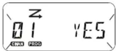
Press the enable (YES) or disable (NO) button
ON/SCAN (SCANNING). Press the SNB1 or SB2 key to scan all channels. After selecting the desired scan settings, press the key
("Menu") to save and proceed to the next step, or turn off the radio to exit without saving. The scan list menu can also be configured using CPS.
Using the lower register is not possible.
Press and hold the PTT key to save changes and return to the "Channel Alias Mode" menu, where you can select the next channel for editing, or turn off the radio to exit without saving.
If the PTT key is pressed, you can stop the transmission by setting the shutdown timer.
Reverse pulse
The reverse pulse suppresses unwanted noise (residual noise) during the loss of carrier detection. For compatibility with other radio stations, you can select values equal to 180 or 240.
The previous pages describe a far from complete list of CPS functions. According to the user programming manual, many possibilities are offered. For detailed information, refer to the CPS help file. - Some functions available for programming with CPS may vary depending on the radio model.
CLONING RADIOS
You can clone the profiles of the radio and the series of the source radio to the target radio using one of the following 3 methods:
Using a multi-charger (accessory purchased separately). Using single chargers and a cloning cable (accessory purchased separately). Using CPS (free download).
Cloning with a multi-charger
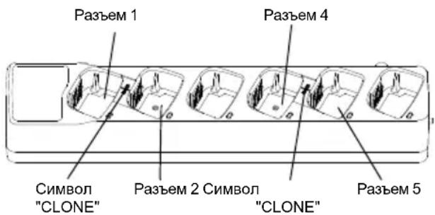
For cloning with a multi-charger, you need at least two radios:
- The source radio (its profile will be cloned or copied) and
- The target radio (its profile will be cloned using the source radio's profile).
To clone, the source radio must be placed in slot 1 or 4, and the target radio must be placed in slot 2 or 5; the slots of the multi-unit charger correspond as follows:
- Slot 1, 2, 4, 5
When cloning, it is not necessary to connect the multi-unit charger to the network, but the batteries of all radios must be charged.
- 1. Turn on the target radio and place it in one of the slots of the multi-unit charger. 2. Turn on the source radio, performing the following sequence of actions:
- Simultaneously press and hold the PTT and SB2 buttons when turning on the radio.
- Hold the buttons for 3 seconds until the cloning beep sounds.
3. Place the source radio in the source slot, the target slot, which was selected in step 1. Press and release the SB1 button. 4. Upon completion of cloning, the source radio will report the result: "successful" (cloning completed successfully) or "fail" (cloning failed). If the source radio is equipped with a display, it will show "Pass" (success) or "Fail" (failure). Within 5 seconds, a beep will sound. 5. To finish the cloning process, turn off and on the radio to exit cloning mode.
More detailed cloning information can be found in the instructions supplied with the multi-unit charger.
When using the multi-unit charger, use the Motorola PMLN6385_ power supply.
Notes:
· In case of unsuccessful cloning, see "If cloning fails" on page 53. - For cloning to succeed, the source and target radios must belong to the same frequency band type. - The numbering of slots on the multi-unit charger is from left to right. © Motorola Solutions. - Radios programmed for the extended frequency band (446.00625-446.19375 MHz) do not support cloning with older radios that support eight frequencies.
CPS cable and cloning cable (optional accessory)
The CPS cable and cloning cable are intended for use with XT and XTNi series radios. The cloning cable connects different models of the XT and XTNi series.
CPS cable is intended for
programming Motorola radios of the NT series. Make sure that the cable switch is in the "Flash" or "CPS" position. When programming radios of the XTNi series with the CPS cable, make sure that the cable switch is in the "CPS" position and that the USB converter from the CPS cable kit is connected to it.
- The cloning cable supports cloning:
- For radios of the XT series: make sure that the cable switch is in the "Cloning" or "Compatibility" position. - For radios of the XTNi series: make sure that the switch is in the "Compatibility" position, and to each connector of the cloning cable, connect a USB converter. - For radios of the XT and XTNi series: make sure that the cable switch is in the "Compatibility" position, use the USB converter for simultaneous charging of XTNi devices. The cloning cable kit includes 1 USB converter.
CPS cable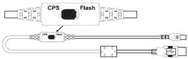
Cloning cable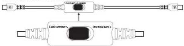
USB converter
Cloning radios using the cloning cable (optional accessory)
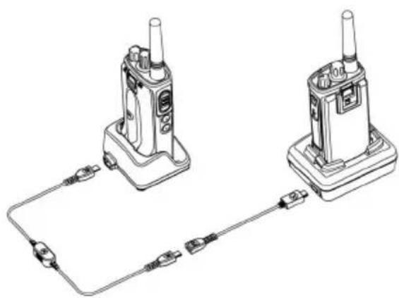
Operating instructions
Information about cloning with the CPS can be found in the following sources:
- CPS Help file, section "Content and Index" -> "Cloning Radios"; - Instructions for using the CPS programming cable.
Charging device with power supply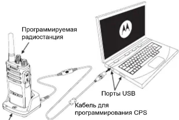
Troubleshooting
Do not use the device until it is completely dry.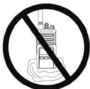
Table of Frequencies and Codes
This section provides information about frequencies and codes. They are convenient for use with transceivers of Motorola Solutions XT series with corporate radios. Most frequency values coincide with the values of the XTNi series radios.
Channel frequency and CTCSS/DPL code for interference-free operation by default
DPL Code DPL Code DPL Code
| 139 | ИнBERТИРОВАнны DPL 48 |
| 140 | ИнBERТИРОВАнны DPL 49 |
| 141 | ИнBERТИРОВАнны DPL 50 |
| 142 | ИнBERТИРОВАнны DPL 51 |
| 143 | ИнBERТИРОВАнны DPL 52 |
| 144 | ИнBERТИРОВАнны DPL 53 |
| 145 | ИнBERТИРОВАнны DPL 54 |
| 146 | ИнBERТИРОВАнны DPL 55 |
| 147 | ИнBERТИРОВАнны DPL 56 |
| 148 | ИнBERТИРОВАнны DPL 57 |
| 149 | ИнBERТИРОВАнны DPL 58 |
| 150 | ИнBERТИРОВАнны DPL 59 |
| 151 | ИнBERТИРОВАнны DPL 60 |
| 152 | ИнBERТИРОВАнны DPL 61 |
| 153 | ИнBERТИРОВАнны DPL 62 |
| 154 | ИнBERТИРОВАнны DPL 63 |
| 155 | ИнBERТИРОВАнны DPL 64 |
| 156 | Инberгторазовский DPL 65 |
| 157 | Инberгторазовский DPL 66 |
| 158 | Инberгторазовский DPL 67 |
| 159 | Инberгторазовский DPL 68 |
| 160 | Инberгторазовский DPL 69 |
| 161 | Инberгторазовский DPL 70 |
| 162 | Инberгторазовский DPL 71 |
| 163 | Инberгторазовский DPL 72 |
| 164 | Инberгторазовский DPL 73 |
| 165 | Инberгторазовский DPL 74 |
| 166 | Инberгторазовский DPL 75 |
| 167 | Инberгторазовский DPL 76 |
| 168 | Инberгторазовский DPL 77 |
| 169 | Инberгторазовский DPL 78 |
| 170 | Инberгторазовский DPL 79 |
| 171 | Инberгторазовский DPL 80 |
| 172 | Инberгторазовский DPL 81 |
| 173 | ИнBERТИРОВАнны DPL 82 |
| 174 | ИнBERТИРОВАнны DPL 83 |
| 175 | ИнBERТИРОВАнны DPL 84 |
| 176 | ИнBERТИРОВАнны DPL 85 |
| 177 | ИнBERТИРОВАнны DPL 86 |
| 178 | ИнBERТИРОВАнны DPL 87 |
| 179 | ИнBERТИРОВАнны DPL 88 |
| 180 | ИнBERТИРОВАнны DPL 89 |
| 181 | ИнBERТИРОВАнны DPL 90 |
| 182 | ИнBERТИРОВАнны DPL 91 |
| 183 | ИнBERТИРОВАнны DPL 92 |
| 184 | ИнBERТИРОВАнны DPL 93 |
| 185 | ИнBERТИРОВАнны DPL 94 |
| 186 | ИнBERТИРОВАнны DPL 95 |
| 187 | ИнBERТИРОВАнны DPL 96 |
| 188 | ИнBERТИРОВАнны DPL 97 |
| 189 | ИнBERТИРОВАнны DPL 98 |
PL/DPL codes (continuous)
Top buttons 10
Side buttons 11
Lithium-ion battery 11
Batteries and chargers 13
CPS (Customer Programming Software) -
software 41
Cloning with CPS (Customer
Programming Software)
-software 47
Troubleshooting 49
SOFTWARE COPYRIGHT
Push-to-Talk button (PTT)
Lithium-Ion (Li-Ion) Battery .11
BATTERIES AND CHARGERS. . . .13
Inserting the Lithium-Ion (Li-Ion) Battery 14
Removing the Lithium-Ion (Li-Ion) Battery 14
PROGRAMMING RX (SIGNAL) CODES (CTCSS/DPL) 35
PROGRAMMING THE ENCRYPTION FEATURE 36
SCANNING 37
CTCSS AND PL/DPL CODES .55
MOTOROLA SOLUTIONS LIMITED
WARRANTY 60
ACCESSORIES. 62
GARANTI 60
ACCESSORIES. 62
ACCESSORIES 62
BATTERY 62
CABLES 62
CHARGERS 63
CARRYING ACCESSORIES 63
COMPUTER SOFTWARE COPYRIGHT
Lithium-Ion (Li-Ion) Battery
Installing the Lithium-Ion (Li-Ion) Battery
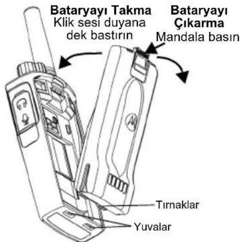
Removing the Lithium-Ion (Li-Ion) Battery
- TURN THE RADIO OFF.
- While removing the battery, press the battery latch and push it downward.
- Remove the battery from the radio.
Table 1: Li-Ion Battery Life with 0.5 Watt Tx Power
PROGRAMMING RX (SIGNAL) FREQUENCIES
PROGRAMMING RX (SIGNAL) CODES (CTCSS/DPL)
PROGRAMMING THE ALARM FEATURE
Component layout 9
Control buttons 10
Channel selection button 10
Accessories section 10
Model name sticker 10
Microphone 10
Antenna 10
Signal indicator 10
Front buttons 10
Rear buttons 11
Lithium-ion battery 11
Batteries and charging device 13
Battery characteristics and charging methods 13
Lithium-ion batteries 13
Installing the battery 14
Removing the battery 15
Charging block with charger and cable for inserting the device . . . 15
Block. 16
Charging the battery 17
Charging with the charger on one and with the cable for inserting the device .17
Light indicators of the charger with cable on one device. 19
Removing the battery from the device. 20
Calculating the charging time .21
Preparing for operation 24
Turning on and off the radio 24
Adjusting the volume. 24
Indications on the display 24 Selecting the radio channel .25 Volume of notifications and monitoring 25 During operation 25
Power indicator of the signal and channel occupancy indicators. .26
Operating range 26 Light indicator during operation 28 Setting «Free hands»/Voice control function VOX. 29
Cymicha raphiTypa VOX .29 HanaHTyBaHHaYTInBocTi iVOX. .29 PiicnIIOBaMikpoΦoHa. 30
PexnM roJocoboro KepyBaHna 6e3 BnkOpncTahnra rapHiTypn (iVOX). . . .30 KopncTyBaHnra rOJocOBIO nIka3KOIO y KopncTyBaucbKomy peKmMi. .30 YbIMKHeHHJXnBJIeHHJ-TOHaJIbHnpeXm. 30 BIDHOBNHnCTaHdapTHNX HanaHTyBaHb 31 O3ByuBaHHKJIaBiaTypn. .31
БлOKуВанн/р036лOKуВанн knabiaotypn 31
Onui MeHIO. 31
HanaTuBaHHaYtTnIBOcTipexmV VOX/iVOX3aDOnOMoROMeHIO.32 HanaTuBaHHaYtIINBocTipeKIMy VOX/iVOX-Ⅱ3 CPS 32 MeHIO niDCnJIbOvau mIKpofoHa 32 PibehPiicnIeHHaMikpOPOHa rapHItypu 33 ToHaJIbHI BnKIINIKU 34 MeHIO nepeniky cKaHyBaHHra 35
PporpamOBaHI yHKui 36
《Advanced Configuration Mode》(PexkIM po3uHpeHnx MOxNIOBocTei HanaSTyBaHHa) 36 PporpaMyBaHHaacToRx (npnMaHHa) .37 IporpamyBaHHaKOiB (CTCSS/DPL) Rx (npnMaHna). 37 IporpamyBaHHaYHKiCiSKpeM6JIIOBaHHa 38 CkaHyBaHHa 39
IporpamyBaHHn IepeNiky cKaHyBaHHn .40
3MiHHeHH Ha3Bn KaHaJy .41
BudaeHHHe6aKaHx KaHaJIb. 42
KomiIOTepHe nporpaMHe 3a6e3neueHnna I
iHDbIyauJIbHoro nporpaMyBaHHa(CPS) .42
Taimepo6mexeHHaucypepaui.43
Ta6nui yactot Ta kOIB 55
KoI CTCSS Ta PL/DPL. 57
Motorola Solutions company. 62
Safety Information
Product Safety and RF Exposure Compliance

Warnings
Before using this product, read the operating instructions and familiarize yourself with the RF exposure information contained in the booklet titled "Product Safety and RF Exposure," which is included with the radio.
WARNING!
In accordance with the requirements of the Federal Communications Commission (FCC), this device is intended solely for occupational use.
For a list of Motorola Solutions-approved batteries, chargers, and other accessories, visit the website:
www.motorolasolutions.com
SAFETY INFORMATION FOR BATTERIES AND CHARGERS
This document contains important safety and operating instructions. Read all instructions carefully and keep them for future reference.
Before using the charger or battery, read all instructions and warning labels on
- the charger, battery, and radio that uses the battery.
- To reduce the risk of injury, use only batteries approved by Motorola Solutions. These batteries are explosion-proof and may cause injury and material damage.
- Use of accessories not recommended by Motorola Solutions may lead to damage, electric shock, or injury.
- To avoid electric shock and fire, when unplugging the charger, pull the plug, not the cord. 4. Use of extension cords is allowed in case of extreme necessity. Use of extension cords that do not meet the requirements may cause fire or electric shock. If use of an extension cord is necessary, make sure it is used with a wire of 18 AWG for a length of 30.48 m (100 feet), and 16 AWG for a length of 45.72 m (150 feet).
- To reduce the risk of damage, electric shock, or injury, do not use defective or damaged chargers. Return them to a certified Motorola Solutions representative for service.
- Do not disassemble the charger; it is not repairable and replacement of defective parts is not possible. Disassembling the charger involves a risk of electric shock and damage.
- To reduce the risk of electric shock, before performing any maintenance or cleaning, disconnect the charger from the AC outlet.
SAFETY INSTRUCTIONS
-When charging the battery, unplug the charger. The charger is not intended for outdoor use. Use it only in dry premises/conditions. -Connect the charger only to properly grounded power sources with a fuse or circuit breaker installed, with the appropriate rating (as indicated on the product). -To disconnect the charger from the mains voltage, pull the main plug from the outlet.
- The outlet to which this device is connected must be located near and easily accessible.
- If the device includes fuses, when replacing them, ensure that the type and class of the new fuses meet the requirements of the device instructions.
- Maximum temperature of the charging source must not exceed 40°C (104°F). The output power level of the charging source must not exceed the value indicated on the label on the bottom of the charging device. The device must be placed in a location where its contact with water, oil, or pressure is impossible, and where it cannot be stepped on or knocked over.
Precautions
In this manual, the following is used
model XT460 from the XT series of radio transceivers.
Model name and its technical characteristics
Indicated in the lower part of the radio:
Table 1: Characteristics of the XT460 radio
| Моdenь | ДIANAZON ЧаСТОТ | ПOTУЖNICТБ пeredавача (BaTT) | КИБКICTБ КаналíВ | АNTЕНА |
| XT460 PMR446 0,5 16 He3HIMHA | ||||
BATTERIES AND CHARGING DEVICES
Radio transceivers XT460 are supplied with batteries of various capacities, depending on the resource.
CHARACTERISTICS OF BATTERIES AND CHARGING METHODS
Lithium-ion batteries
Radio transceivers of the XT series are supplied with lithium-ion batteries. To ensure maximum capacity and optimal operational characteristics, the battery must be fully charged before initial use.
The battery life is determined by several factors. The most significant factors are regular full charging of the batteries and deep discharge in each cycle. Typically, the most full charging is performed
The deeper the battery is discharged, the fewer charge-discharge cycles it can withstand. For example, a battery that receives a full charge and is completely discharged several times a day will withstand fewer cycles than a battery that is recharged to 50%. In addition, a battery that is not fully charged and is discharged on average no more than 25% will last longer.
Motorola Solutions batteries are designed specifically for use with Motorola Solutions charging devices, which, in turn, are designed for charging such batteries. Using charging devices from other manufacturers may result in battery damage and void the battery warranty.
Optimal battery charging temperature is 25°C (77°F). Charging a cold battery (below 10°C [50°F]) may cause a sudden drop in electrical output, and in some cases, even battery failure. Charging an overheated battery (above 35°C [95°F]) leads to reduced capacity, negatively affecting the operational characteristics of the radio. To ensure optimal battery charging conditions, follow the specified temperature conditions. The charging equipment from Motorola Solutions is equipped with temperature sensors.
Ukrainian
Installing the battery
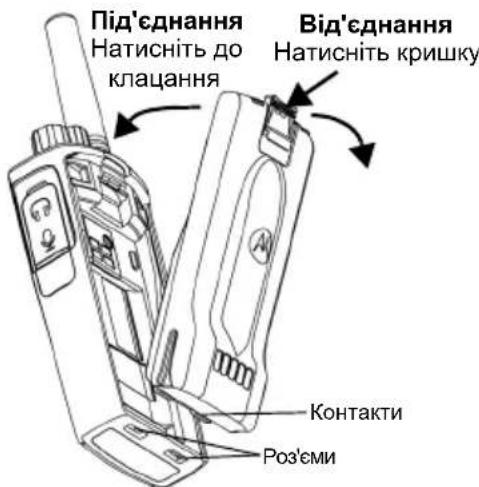
- Turn off the radio.
- Remove the battery from the Motorola Solutions charger and align the contacts on the bottom of the battery with the contacts on the bottom of the radio housing. 3. Press down on the top edge until the battery clicks into place.
Note: For more information on battery resources, see the "Batteries" section on page 13.
Removing the battery
- Turn off the radio. 2. Slide the battery latch down and hold it pressed.
- Remove the battery from the radio.
Table 1: Battery resource for 0.5 Watt radios of the TX series
| Тип akумлаятора | Реким ekономii Зapяду ВИМК. | Реким ekономii Зapяду УВIMK. |
| Стонданчий 16 Підвишени смностi | rogenin 20 rodiin | |
| H/D H/D |
Power supply and charging unit with plug for inserting the device
Charging unit with plug for inserting the device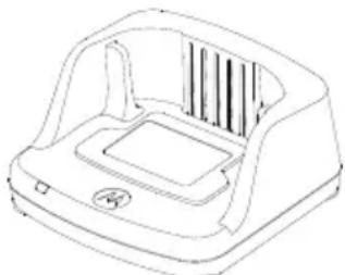
Power supply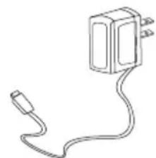
The radio package includes one single-unit charging unit, one power supply (also called a transformer), and a set of adapters.
The ability to switch the power supply allows you to use it with any adapter from the supply kit.
The adapter must be inserted into the region where it is used.
After determining where the adapter is located relative to the power outlet, perform the installation as described:
Note: The adapter shown in the figures is for demonstration purposes only. The adapter you need to install may be different. To remove the adapter, press it inward.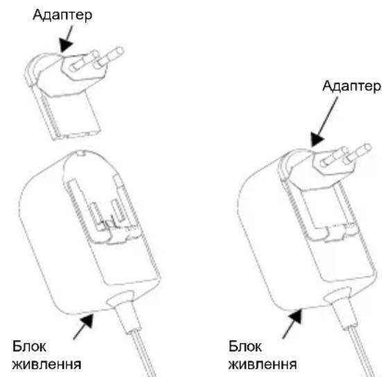
Insert the adapter pins into the power block and press the adapter down until it clicks into place.
To charge the device or the power block, connect it to a certified charger with a USB cable.
Estimated charging time
The table shows the estimated charging time for the battery. More information can be found in the section "Battery" on page 64.
Table: Estimated charging time for the battery
TURNING ON/OFF THE RADIO
To turn on the radio, rotate the "ON/OFF/VOLUME" knob clockwise. The radio will emit one of the following signals:
- An audible signal indicating power-on and the channel number, or a voice message indicating the battery level and channel number, or a tone (audible signal) and the LED indicator will blink red.
To turn off the radio, rotate the "ON/OFF/VOLUME" knob counterclockwise until it clicks, and the LED indicator turns off.
VOLUME ADJUSTMENT
Rotate the "ON/OFF/VOLUME" knob clockwise to increase volume, and counterclockwise to decrease it.
Note: When adjusting the volume, do not hold the radio too close to your ear.
Channel busy indicator and channel free indicator
On certain frequencies, the radio station's channel busy indicator (with or without squelch) is active, while the channel free indicator lights up continuously. The indicator changes from 1 (weak) to 6 (strongest) depending on the radio station's reception range. In reception mode, the channel busy indicator is displayed with squelch.
Note: Interference on the transmission path may affect the strength of the incoming signal.
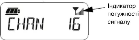
RANGE
The purpose of creating XT series radios is to maximize operational characteristics and increase communication range in open space. The recommended distance between radios to avoid mutual interference should be at least 1.5 meters. For XT460 series radios, the coverage area is 16250 square meters, 13 floors, and 9 km in open terrain.
Communication range depends on the terrain. The presence of obstacles such as concrete structures, dense green spaces, and also the use of radios indoors or in transport affects the communication range. The optimal radius is 9 km in open terrain. With buildings and trees in the signal path, the communication range will be average. The range will be minimal if dense green spaces or forests are in the signal path.
To ensure reliable communication between two radios, they must be set to the same channel, frequency, and squelch code. To do this, the radio must be programmed and the settings saved:
- Channel: The channel number used by the radio (depending on the model).
- Frequency: The frequency on which transmission and reception are carried out.
- Squelch code: By selecting a combination of codes, interference can be reduced.
- Scrambling code: Codes are used to create sound during transmission, so the message can only be understood with the appropriate code.
Detailed instructions for setting the frequency and CTCSS/DPL codes for channels are given in the "Advanced Configuration Mode" on page 36.
RADIO INDICATORS
| CTAH PADI OCTAHZI CBITNOBA IHDNIKAZI |
| Зminеня нааз布局 Каналу Сер党支部 пььсуочи |
| Канал заимятынжовограду постий |
| Рек imm клоунваняжовограду постийпььсуочи |
| Виконы ся клоунваняжовограду постий |
| Heucymbа полеска пд часувIMКеня львения |
| Изbethк рівень зараду akумлąтopa |
| Вимкинся радioc Stanцü chereşпьbeth рівень зараду akумлąтopa |
| Monitop Сbitлiodюний indinkatord Вимкино |
| Увимкинся жинления Пocstий чер党支部 пььсуочи |
| Рек imm порамуваши - саночіквань / Ррогамуваши Каналíв |
| Рек imm санунваня Сер党支部 пььсуочи |
| Передача (Тx)/Прийом (RX) Сер党支部 постий |
| Рек imm VOX/iVOX Сер党支部 постийпььсуочи |
HEADSET "HANDS-FREE / VOX FUNCTION"
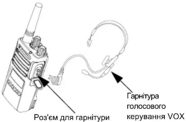
For XT series radios, the voice control (VOX) function is disabled by default using the default VOX accessory.
Default VOX accessory
The default factory setting for VOX accessory sensitivity is medium level («2»). Before using the VOX accessory with the help of the Customer Programming Software (CPS), set the VOX sensitivity level to a value different from «2». Then perform the following steps:
- Turn off the radio.
- Open the cover that closes the accessory connector. 3. Insert the accessory plug into the connector.
- Turn on the radio. The green indicator will blink briefly.
- While bringing the accessory to your ear, adjust the sensitivity level.
- To start a transmission, speak into the microphone, and to start receiving, stop talking. 7. The voice control function VOX can be temporarily disabled by pressing the PTT button or simply removing the accessory.
The VOX connection can also be made using the programming cable, without using CPS.
Note: To order the accessory, contact your local Motorola Solutions sales representative.
Adjusting VOX sensitivity
The sensitivity of the radio or microphone accessory can be adjusted according to different working environment conditions. VOX sensitivity can be programmed using CPS or the menu button.
By default, the value is set to
«3». Possible VOX sensitivity values:
-1 = Triggers at high input level -2 = Medium sensitivity -3 = Triggers at low input level
The microphone sensitivity can be adjusted according to user needs and working environment conditions.
To adjust this option, use the Menu button or CPS. By default, the microphone mute is set to level "2" (medium suppression).
Voice Operated Transmission (VOX) mode
To activate VOX mode, while the radio is on, press the PTT button briefly. The radio will beep. - VOX mode can be temporarily disabled by pressing the PTT button. - A short press of the PTT button again re-enables VOX mode.
Note.
Note that transmission starts with a slight delay after you start speaking. - For detailed VOX/VOX sensitivity settings, see "VOX/VOX sensitivity settings via Menu" on page 32.
Using the voice prompt in user mode
To activate or deactivate the voice prompt in user mode, while the radio is on, briefly press the SB1 button. (The default setting is "ON").
Enable/Disable Tonal Signaling
To activate or deactivate the tonal signaling during transmission, while the radio is on, press and hold the SB1 and SB2 buttons simultaneously for 2-3 seconds until a short beep is heard, indicating that the tonal signaling is enabled or disabled.
Restore Factory Defaults
The "Restore Factory Defaults" function restores all radio settings to the factory defaults. To restore factory defaults, while the radio is on, press and hold the PTT, SB1, and SB2 buttons simultaneously until you hear a high-pitched beep.
Keypad Tones
Keypad tones can be enabled or disabled by briefly pressing the SB2 button while the radio is on, until a high-pitched beep is heard.
Press the key 1a, 06 to select the desired value of the tonal key (0, 1, 2, 3, 4, 5 or 6). Each selected tonal key option will be sounded (except the value "0").
After the desired tonal key is selected, press the (Menu) key to save the setting and proceed to the next step, or turn off the radio to exit this mode without saving the setting. To set the tonal keys, you can also use the CPS (Customer Programming Software).
Scan list menu
The scan function can be activated for each channel frequency in the scan list menu. To enter the scan menu, press and hold the (Menu) key until the channel name appears on the display. The radio will then show a prompt for enabling the scan function ("YES" or "NO"):
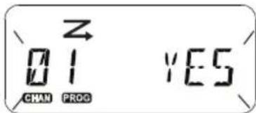
To activate ("YES") or disable ("NO") the scan function, press the key. To go through all channels, press the SB1 or SB2 key. After the desired scan setting is selected, press the (Menu) key to save the setting and proceed to the next step, or turn off the radio to exit this mode without saving the setting. To set the scan list menu, you can also use the CPS.
PROGRAMMING FUNCTIONS
It is recommended to program all radio functions using the CPS software and the programming cable.
The CPS software can be downloaded from the website www.motorolasolutions.com.
(EXTENDED PROGRAMMING MODE)
To enter the "Programming Mode" ("Reprogramming") while the radio is on, simultaneously press and hold the PTT and SB1 keys for about 3 seconds. You will hear a voice prompt "Channel Number", indicating the transition to programming mode. The indicator will blink with a green light. When the radio enters "Programming Mode", the display shows PROG
The corresponding symbol and the name of the current channel appear, indicating that you can use the rotary knob to select a channel for programming.
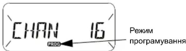
In "Programming Mode", you can set different values for each channel, selecting among the available programming modes:
· Frequency - CTCSS/DPL codes (squelch codes) - Scrambling - Scanning.
- To exit the "Selection and Programming Modes" without saving changes, briefly press the PTT or the key
(Menu).
- To change, press and hold the PTT button. The radio will return to the last expected programming mode.
- If the radio is in the "Programming Mode" state, press and hold the PTT button to exit "Programming Mode".
- When returning to the beginning of the list after going through all items and "Programming Mode", all changes will be automatically saved, even if the radio is turned off. By turning off the radio, you can exit any "Programming Mode" without saving changes (if you did not return to the beginning, having gone through all items).
PROGRAMMING RX FREQUENCY (RECEPTION)
Select the channel to be programmed, briefly press the PTT button or key (menu) to cycle through all items until you reach "Programming Frequency".
The radio display will show the current frequency.
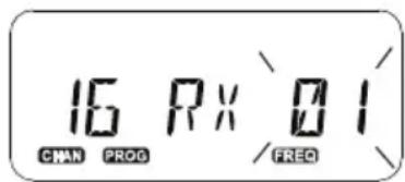
To program the desired frequency, scroll through the list up and down using the keys until you find the desired frequency value. Press and hold the PTT button to exit and save the setting, or briefly press the PTT button to move to the next programming item without saving the setting.
Select the channel number, briefly press the PTT button or key (menu) to start changing the channel name.
The symbol that can be changed will start blinking. The blinking symbol will be the cursor.
- Change the symbol by pressing the keys ▲ and
▼ until you find the desired one. To move to the next symbol on the right, press
the key (menu). The order of symbols when pressing the keys will be as follows: in alphabetical order from A to Z, " " (space), [0 - 9] and special symbols. Symbols can be entered only in uppercase (capital letters).
Press and hold the PTT button to save changes and return to the "Channel Name Setting Mode" for selecting another channel and changing its name, or exit the menu without saving changes by turning off the radio.
Note: If the channel name is left blank, pressing and holding the PTT button will not lead to saving changes and exiting the current mode until the name is entered.
The Delete Unwanted Channels function allows you to temporarily disable some channels from the scanning list. This function is used when an "unwanted" channel has a lot of traffic that interferes with and complicates scanning of other channels.
To delete a channel from the scanning list:
- Start scanning by pressing the SB2 button (*). - Wait until the radio tunes to the channel that you need to delete. To delete this channel, press and hold the SB2 button. The channel for which the scanning function is enabled (the priority channel) cannot be deleted. - Scanning in the channel resumes only after exiting the scanning mode, which is done by a short press of the SB2 button; you can also turn the radio off and on again.
Note. (*) Provided that the SB2 button is not programmed for another function.
COMPUTER SOFTWARE FOR CUSTOM PROGRAMMING (CPS)
5.1: Programming the radio using the CPS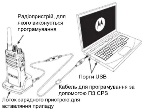
The simplest way to change the radio functions is the Computer Software for Custom Programming (CPS) and the programming cable for CPS*). The web version of the CPS can be downloaded free of charge from the website:
www.motorolasolutions.com
To start programming, place the radio in the charging cradle and connect it to the computer using the CPS programming cable, as shown in Fig. 1 on page 42. Set the switch on the CPS programming cable to "CPS Mode".
The software allows you to program frequencies, PL/DPL codes, as well as other functions, including the transmit time-out timer, scan list, tone signaling, scrambling, the "Reverse Burst" function, and others. The CPS is a very convenient tool that allows you to program from the front panel or limit the ability to change any specified function (for prior approval of the previously programmed settings). In addition, it increases the level of security, allowing you to set passwords for simple radio settings. Detailed information can be found in the "Function Table" section at the end of this user manual.
Note. (*) The CPS programming cable, art. no. HKKN4027_, is an accessory and is sold separately. For information, contact your local Motorola Solutions sales office.
Transmit Time-Out Timer
PROGRAMMING THE RADIOS
The configuration profile of XT series radios can be copied from one radio to another using one of three methods:
- Charger les appareils sur le chargeur de la station d'accueil (équipement supplémentaire), - chargeurs pour appareils et câbles pour connecter et charger les deux radios (équipement supplémentaire),
- CPS (programme chargé sans fil)
Chargement à l'aide du chargeur de la station d'accueil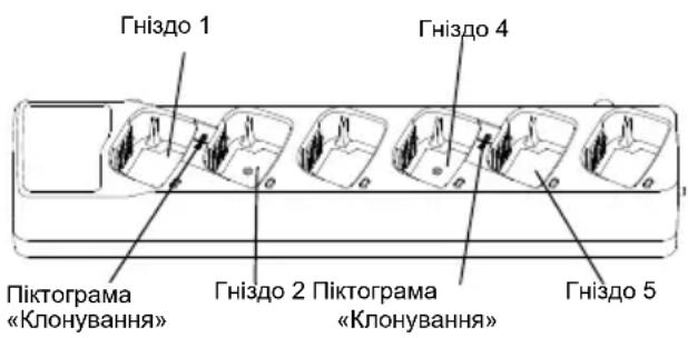
DÉPANNAGE
Ne pas immerger dans l'eau, ne pas utiliser de sprays ou de solvants
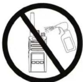
Si de l'eau pénètre dans la radio...
Éteignez les radios, retirez les batteries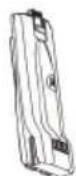
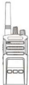
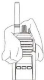
Séchez avec un chiffon sec, n'utilisez pas la radio tant qu'elle n'est pas complètement sèche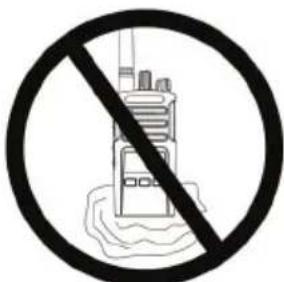
Ukrainien
TABLEAU DES FRÉQUENCES ET DES CODES
Dans cette section, des tableaux avec des données sur les fréquences et les codes sont fournis. Les données de ces tableaux sont nécessaires pour établir la communication entre les appareils de la radio bidirectionnelle de la série Motorola Solutions XT et d'autres radios commerciales. Les fréquences des canaux correspondent aux canaux de la radio de la série XTN.
Tableau standard des fréquences et des codes de programmation
© Motorola Solutions, Inc., 2013, 2018.
Tous droits réservés.
ACCESSOIRES
© Motorola Solutions, Inc., 2013, 2018.
All rights reserved.

MOTOROLA SOLUTIONS
Motorola Solutions, Inc.
500 W Monroe Street
Chicago, IL 60661 U.S.A
http://www.motorolasolutions.com

68012009069-BA

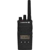
- OPEN SOURCE SOFTWARE LEGAL NOTICES
- CONTENTS
- COMPUTER SOFTWARE
- SAFETY
- PRODUCT SAFETY AND RF EXPOSURE COMPLIANCE
- ATTENTION
- BATTERIES AND CHARGERS SAFETY INFORMATION
- OPERATIONAL SAFETY GUIDELINES
- RADIO OVERVIEW
- ON/OFF/VOLUME KNOB
- CHANNEL SELECTOR KNOB
- ACCESSORY CONNECTOR
- MODEL LABEL
- MICROPHONE
- ANTENNA
- LED INDICATOR
- FRONT BUTTONS
- MENU BUTTON
- PROGRAMMABLE BUTTON
- SIDE BUTTONS
- PUSH-TO-TALK (PTT) BUTTON
- SIDE BUTTON 1 (SB1)
- SIDE BUTTON 2 (SB2)
- THE LITHIUM-ION (LI-ION) BATTERY
- BATTERIES AND CHARGERS
- BATTERY FEATURES AND CHARGING OPTIONS
- ABOUT THE LI-ION BATTERY
- REMOVING THE LITHIUM-ION (LI-ION) BATTERY
- POWER SUPPLY AND DROP-IN TRAY CHARGER
- HOLSTER
- CHARGING THE BATTERY
- CHARGING WITH THE DROP-IN TRAY SINGLE UNIT CHARGER (SUC)
- CHARGING A STAND-ALONE BATTERY
- DROP-IN TRAY CHARGER LED INDICATORS
- BATTERY METER
- RATED CHARGING TIME
- CHARGING A RADIO AND BATTERY USING A MULTI-UNIT CHARGER (MUC) (OPTIONAL ACCESSORY)
- NOTE
- GETTING STARTED
- ADJUSTING VOLUME
- READING THE DISPLAY
- SELECTING A CHANNEL
- TALKING AND MONITORING
- NOTES
- RECEIVING A CALL
- SIGNAL STRENGTH INDICATOR AND CHANNEL BUSY INDICATORS
- TALK RANGE
- RADIO LED INDICATORS
- HANDS-FREE USE/VOX
- WITH COMPATIBLE VOX ACCESSORIES
- SETTING IVOX SENSITIVITY
- MICROPHONE GAIN
- HANDS FREE WITHOUT ACCESSORIES (IVOX)
- TOGGLE VOICE PROMPT IN USER MODE
- POWER UP - TONE MODE
- RESET TO FACTORY DEFAULTS
- KEYPAD BEEPS
- KEYPAD LOCK/UNLOCK
- MENU OPTIONS
- SETTING VOX /IVOX SENSITIVITY - MENU
- SETTING VOX /IVOX SENSITIVITY - CPS
- MICROPHONE GAIN MENU
- MICROPHONE ACCESSORY GAIN LEVEL
- CALL TONES
- YOU CAN ENABLE THE CHANNEL SCANNING FEATURE FOR A SPECIFIC CHANNEL FREQUENCY FOR THE RADIO IN SCAN LIST MENU. TO ENTER THE SCAN MENU, PRESS THE (MENU) BUTTON UNTIL THE RADIO DISPLAYS THE CHANNEL NUMBER, THE CCOM AND BLINKS THE CURRENT SETTING (YES' OR NO') AS FOLLOWS
- PROGRAMMING FEATURES
- PROGRAMMING RX (RECEPTION) FREQUENCIES
- PROGRAMMING RX (RECEPTION) CODES (CTCSS/DPL)
- PROGRAMMING SCRAMBLE
- SCAN
- PROGRAMMING SCAN LIST
- EDITING CHANNEL ALIAS NAME
- NUISANCE CHANNEL DELETE
- CUSTOMER PROGRAMMING SOFTWARE (CPS)
- TIME-OUT TIMER
- REVERSE BURST
- CLONING RADIOS
- CPS AND CLONING CABLES (OPTIONAL ACCESSORY)
- CPS CABLE
- CLONING CABLE
- USB CONVERTER
- CLONING RADIO USING THE RADIO TO RADIO (R2R) CLONING CABLE (OPTIONAL ACCESSORY)
- OPERATING INSTRUCTIONS
- WHAT TO DO IF CLONING FAILS
- CLONING USING THE CUSTOMER PROGRAMMING SOFTWARE (CPS)
- TROUBLESHOOTING
- USE AND CARE
- FREQUENCY AND CODE CHARTS
- CTCSS AND PL/DPL CODES
- MOTOROLA SOLUTIONS LIMITED WARRANTY
- WARRANTY INFORMATION
- WHAT IS NOT COVERED BY THE WARRANTY
- ACCESSORIES
- CARRY ACCESSORIES
- ADJUSTING THE AUDIO LEVEL
- CPS (CUSTOMER PROGRAMMING SOFTWARE)
- PTT BUTTON (PUSH-TO-TALK)
- RX (RECEIVE) PROGRAMMING CODES (CTCSS/DPL)
- PROGRAMMING SOFTWARE (CUSTOMER PROGRAMMING SOFTWARE, CPS)
- TRANSPORT ACCESSORIES
- LEGAL NOTE ON OPEN SOURCE SOFTWARE
- PTT (PUSH-TO-TALK) BUTTON
- PROGRAMMING RX (RECEIVE) CODES (CTCSS/DPL)
- PTT BUTTON (PUSH-TO-TALK, PRESS TO TALK)
- LIMITED WARRANTY FOR MOTOROLA SOLUTIONS
- WHAT THE WARRANTY DOES NOT COVER
- PROGRAM CODES (CTCSS/DPL) RX (RECEPTION)
- COPYRIGHT FOR COMPUTER SOFTWARE
- PRODUCT SAFETY
- AND
- COMPLIANCE
- EXPOSURE
- RADIO FREQUENCY RADIATION
- WARNING
- SAFETY INFORMATION FOR HANDLING BATTERIES AND CHARGING DEVICES
- SAFETY INSTRUCTIONS
- EXTERNAL CONTROLS
- VOLUME KNOB / POWER SWITCH
- BUTTONS ON THE FRONT PANEL
- BOKOVAR KHOIIKA 2 (SB2)
- HANDS FREE" MODE WITHOUT USING ACCESSORIES (VOX)
- TURNING ON AND OFF VOICE PROMPTS IN USER MODE
- TONAL SIGNAL FOR POWER ON
- RESET TO FACTORY SETTINGS
- KEYPAD LOCK
- THE GAIN LEVEL OF THE ADDITIONAL MICROPHONE
- CALL SIGNALS
- REVERSE PULSE
- CLONING WITH A MULTI-CHARGER
- CPS CABLE AND CLONING CABLE (OPTIONAL ACCESSORY)
- THE CLONING CABLE SUPPORTS CLONING
- TABLE OF FREQUENCIES AND CODES
- SOFTWARE COPYRIGHT
- PUSH-TO-TALK BUTTON (PTT)
- COMPUTER SOFTWARE COPYRIGHT
- LITHIUM-ION (LI-ION) BATTERY
- INSTALLING THE LITHIUM-ION (LI-ION) BATTERY
- PROGRAMMING RX (SIGNAL) FREQUENCIES
- PROGRAMMING RX (SIGNAL) CODES (CTCSS/DPL)
- PROGRAMMING THE ALARM FEATURE
- SAFETY INFORMATION
- SAFETY INFORMATION FOR BATTERIES AND CHARGERS
- BATTERIES AND CHARGING DEVICES
- CHARACTERISTICS OF BATTERIES AND CHARGING METHODS
- LITHIUM-ION BATTERIES
- INSTALLING THE BATTERY
- REMOVING THE BATTERY
- POWER SUPPLY AND CHARGING UNIT WITH PLUG FOR INSERTING THE DEVICE
- ESTIMATED CHARGING TIME
- TURNING ON/OFF THE RADIO
- VOLUME ADJUSTMENT
- CHANNEL BUSY INDICATOR AND CHANNEL FREE INDICATOR
- RANGE
- RADIO INDICATORS
- HEADSET "HANDS-FREE / VOX FUNCTION
- DEFAULT VOX ACCESSORY
- ADJUSTING VOX SENSITIVITY
- VOICE OPERATED TRANSMISSION (VOX) MODE
- USING THE VOICE PROMPT IN USER MODE
- ENABLE/DISABLE TONAL SIGNALING
- RESTORE FACTORY DEFAULTS
- KEYPAD TONES
- SCAN LIST MENU
- PROGRAMMING FUNCTIONS
- (EXTENDED PROGRAMMING MODE)
- PROGRAMMING RX FREQUENCY (RECEPTION)
- COMPUTER SOFTWARE FOR CUSTOM PROGRAMMING (CPS)
- TRANSMIT TIME-OUT TIMER
- PROGRAMMING THE RADIOS
- DÉPANNAGE
- SI DE L'EAU PÉNÈTRE DANS LA RADIO
- TABLEAU DES FRÉQUENCES ET DES CODES
- ACCESSOIRES
- MOTOROLA SOLUTIONS
Brand : MOTOROLA
Model : XT400
Category : Walkie-talkie