
W 50P - Pump HUSQVARNA - Free user manual and instructions
Find the device manual for free W 50P HUSQVARNA in PDF.
| Product Type | Water Pump |
| Brand | Husqvarna |
| Model | W 50P |
| Inlet/Outlet Dimensions | 50 mm |
| Total Head | 28 m |
| Suction Head | 7 m |
| Maximum Flow Rate | 32 m³/h |
| Fuel Tank Capacity | 3,6 L |
| Oil Tank Capacity | 0,6 L |
| Net Weight / Gross Weight | 25 kg / 27 kg |
| Fuel Type | Unleaded petrol (min. 90 RON) |
| Recommended Engine Oil | Detergent 4-stroke oil (SAE 30 or 10W-30) |
| Engine Model | 168FB |
| Guaranteed Sound Power Level | 108 dB(A) |
| Intended Use | Water drainage or transport to a location |
| Power Source | Internal combustion engine (petrol) |
| Periodic Maintenance | See schedule (daily, 20 h, 50 h, 100 h, 300 h) |
| Cleaning | Manual with soapy water, avoid water in air filter |
| Safety | Read manual, use protections, do not use indoors |
| Main Spare Parts | Air filter, spark plug, strainer, hose |
| Reparability | Authorized workshop for repairs beyond manual |
Frequently Asked Questions - W 50P HUSQVARNA
User questions about W 50P HUSQVARNA
0 question about this device. Answer the ones you know or ask your own.
Ask a new question about this device
Download the instructions for your Pump in PDF format for free! Find your manual W 50P - HUSQVARNA and take your electronic device back in hand. On this page are published all the documents necessary for the use of your device. W 50P by HUSQVARNA.
USER MANUAL W 50P HUSQVARNA
EN Operator's manual 2-17
Introduction.... 2
Safety....5
Assembly....6
Installation....7
Operation....8
Maintenance.... 11
Troubleshooting.... 13
Transportation and storage....14
Technical data.... 16
EC Declaration of Conformity.... 17
Introduction
Product description
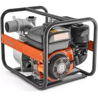
The product is a water pump for transportation of water.
Intended use
The product is used to drain or supply fresh water to and from a location. Do not use the product for other tasks.
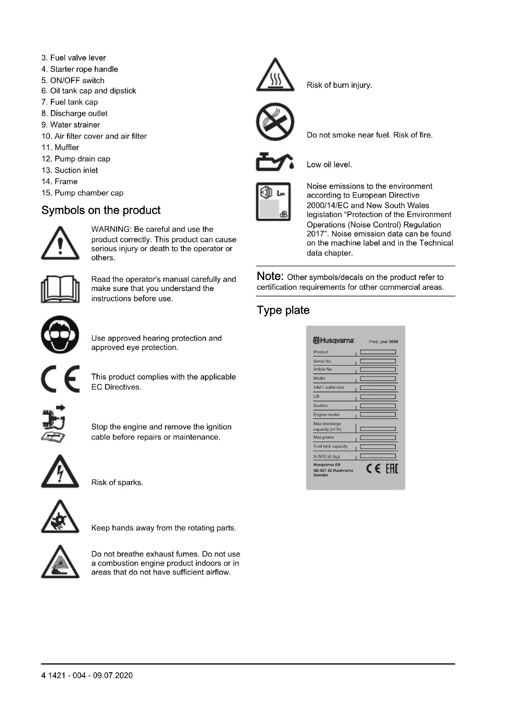
1. Throttle lever 2. Choke lever
- Fuel valve lever
- Starter rope handle
- ON/OFF switch
- Oil tank cap and dipstick
- Fuel tank cap
- Discharge outlet
- Water strainer
- Air filter cover and air filter
- Muffler
- Pump drain cap
- Suction inlet
- Frame
- Pump chamber cap
Symbols on the product

WARNING: Be careful and use the product correctly. This product can cause serious injury or death to the operator or others.

Read the operator's manual carefully and make sure that you understand the instructions before use.

Use approved hearing protection and approved eye protection.

This product complies with the applicable EC Directives.
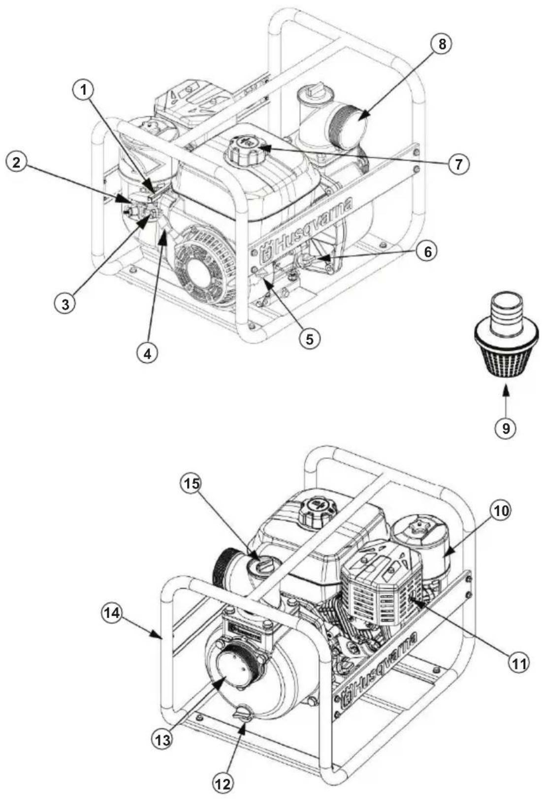
Stop the engine and remove the ignition cable before repairs or maintenance.
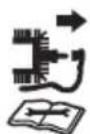
Risk of sparks.
Keep hands away from the rotating parts.

Do not breathe exhaust fumes. Do not use a combustion engine product indoors or in areas that do not have sufficient airflow.
Risk of burn injury.
Do not smoke near fuel. Risk of fire.
Low oil level.
Noise emissions to the environment according to European Directive 2000/14/EC and New South Wales legislation “Protection of the Environment Operations (Noise Control) Regulation 2017”. Noise emission data can be found on the machine label and in the Technical data chapter.
Note: Other symbols/decals on the product refer to certification requirements for other commercial areas.
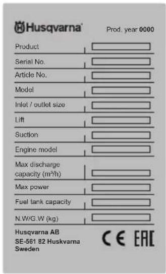
Type plate
Safety
Safety definitions
Warnings, cautions and notes are used to point out specially important parts of the manual.

WARNING: Used if there is a risk of injury or death for the operator or bystanders if the instructions in the manual are not obeyed.

CAUTION: Used if there is a risk of damage to the product, other materials or the adjacent area if the instructions in the manual are not obeyed.
Note: Used to give more information that is necessary in a given situation.
General safety instructions

WARNING: Read and understand the warning instructions that follow before you use the product.
- Read and understand the operator's manual and safety decals on the product before operation. Your safety and the safety of others is your responsibility.
- Obey the instructions in this operator's manual.
- It is not possible to give a warning for each situation that can occur during operation and maintenance of this product. Always be careful and use your common sense.
Safety instructions for operation

WARNING: Read and understand the warning instructions that follow before you use the product.
- Let the engine become cool before transportation or storage of the product.
- You must know how to stop the product quickly if an emergency occurs.
- Know the controls and the correct operation of the product before use.
- If you leave the product without supervision, stop the engine.
- Do not drink the water that comes from the product! The water is not intended for human consumption.
- Do not let children or persons without knowledge of these instructions use the product.
-
Do not operate the product while persons, especially children, or animals are near.
-
Do not put flammable liquids, such as gasoline or oil, in the pump chamber. This can result in fire or explosion and cause serious injury or death to the operator or others. Do not operate the product with sea water, beverages, acids, chemical solutions or any other liquids.
- As the level difference for for operation of the product increases, the pump output decreases. The length, type and dimension of the hoses can significantly affect the pump output.
- Do not operate the product without a strainer.
- Keep body parts away from moving parts.
- The muffler becomes very hot during operation and is hot for some time after operation. Do not touch the muffler when it is hot.
Fuel safety

WARNING: Read the warning instructions that follow before you use the product.
- Fuel is flammable and the fumes are explosive. Be careful with fuel to prevent injury, fire and explosion.
- Do not breathe in the fuel fumes. The fuel fumes are poisonous and can cause injury. Make sure that the airflow is sufficient.
- Do not remove the fuel tank cap or fill the fuel tank when the engine is on.
- Let the engine become cool before you refuel.
- Do not fill fuel in an indoor area. Not sufficient airflow can cause injury or death because of asphyxiation or carbon monoxide.
- Do not smoke near the fuel or the engine.
- Do not put hot objects near the fuel or the engine.
- Do not fill fuel near sparks or flames.
- Before you refuel, open the fuel tank cap slowly and release the pressure carefully.
- Fuel on your skin can cause injury. If you get fuel on your skin, use soap and water to remove the fuel.
- If you spill fuel on your clothing, change clothing immediately.
- Do not fill the fuel tank fully. Heat causes the fuel to expand. Keep a space at the top of the fuel tank.
- Tighten the fuel tank cap fully. If the fuel tank cap is not tightened, there is a risk of fire.
- Before you start the product, move the product to a minimum of 3 m/10 ft from where you refueled.
-
Do not start the product if there is fuel or engine oil on the product. Remove the unwanted fuel and engine oil and let the product dry before you start the engine.
-
Examine the engine for leaks regularly. If there are leaks in the fuel system, do not start the engine until the leaks are repaired.
- Do not use your fingers to examine the engine for leaks.
- Keep fuel in approved containers only.
- When the product and fuel is in storage, make sure that fuel and fuel fumes cannot cause damage.
- Drain the fuel in an approved container outdoors and away from sparks and flames.
Exhaust fumes safety

WARNING: Read the warning instructions that follow before you use the product.
- The exhaust fumes from the engine contain carbon monoxide which is an odourless, poisonous and very dangerous gas. To breathe carbon monoxide can cause death. Because carbon monoxide is odourless and cannot be seen, it is not possible to sense it. A symptom of carbon monoxide poisoning is dizziness, but it is possible that a person becomes unconscious without warning if the quantity or concentration of carbon monoxide is sufficient.
- Exhaust fumes also contain unburned hydrocarbons including benzene. Long-term inhalation can cause health problems.
-
Exhaust fumes that you can see or smell also contain carbon monoxide.
-
Do not use a combustion engine product indoors or in areas that do not have sufficient airflow.
- Do not breathe the exhaust fumes.
- Make sure that the airflow in the work area is sufficient. This is very important when you operate the product in trenches or other small work areas where exhaust fumes can easily collect.
Safety instructions for maintenance

WARNING: Read and understand the warning instructions that follow before you do maintenance on the product.
• Take care of each error that you find on the product. Speak to a servicing dealer if it is necessary and do not operate the product if it is damaged.
- Incorrect maintenance or failure to do maintenance on the product can cause malfunctions which can cause serious injury or death to the operator or others.
- Maintenance or servicing that is not given in this operator's manual, must be done by an approved servicing dealer.
- Do not do maintenance or servicing with the engine on. Stop the product fully before maintenance or servicing and let the engine become cool to prevent burn injuries.
- Be careful around gasoline. Only use solvent that is not flammable to clean the parts of the product. Keep body parts away from hot fuel.
Assembly
Introduction

WARNING: Read and understand the safety chapter before you assemble the product.
To select the correct hoses for the operation
- Use hoses and hose connectors with a supplied hose clamp.
- Make sure that the hoses cannot compress during operation. The hoses must have a strong construction.
- Make sure that the hoses are fully sealed and that there are no types of holes in the hoses.
- Make sure that the suction hose aligns with the dimension of the suction inlet. For information about minimum hose dimension, refer to Technical data on page 16.
- Make sure that the suction hose is not too long for the operation to keep the best result. Obey the instructions for installation of the product. Refer to Installation on page 7.
- Select a short discharge hose with a large diameter to get the best result.
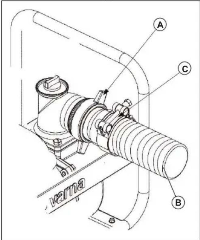
To install the suction hose to the product
- Attach the hose connector (A) to the suction hose (B) with a hose clamp (C). Make sure that the sealing washer for the hose connector is in good condition.
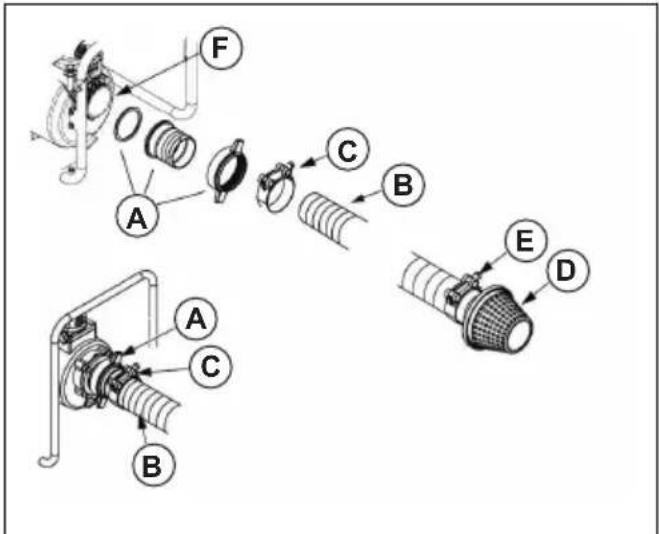
-
Install the strainer (D) at the end of the suction hose with the hose clamp (E).
-
Tighten the hose connector on the pump suction inlet (F).
To install the discharge hose
- Attach the hose connector (A) to the pump outlet.
- Install the discharge hose (B) to the hose connector and tighten the hose clamp (C).
Installation
Introduction

WARNING: Read and understand the safety chapter before you install the product.
To install the product
-
Put the product on stable and level ground near the water surface.
-
Make sure that the product has a free space of a minimum of 1 m.
-
Make sure that there are no flammable objects near the engine.
-
Make sure that the level difference for the suction hose (A) is as low as possible for the operation. The level difference for the suction hose must not be more than 7.5 m/25 ft.
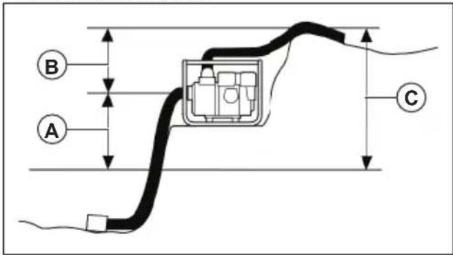
Note: The level difference for the discharge hose (B) can be more if it is necessary. But, a lower total level difference (C) gives the best result.
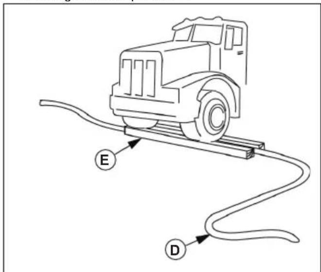
- If the discharge hose (D) must be installed across a road, put it perpendicular to the flow of the traffic. Put long wooden blocks (E) on the 2 sides of the discharge hose for protection.
Operation
Introduction

WARNING: Read and understand the safety chapter before you use the product.
To do before you operate the product
• Make sure that the product is on level ground.
- Make sure that the ON/OFF switch is in the OFF position.
- Examine the product for damages. Make sure that there are no fuel or oil leaks.
- Remove unwanted material from the product. Clean carefully around the muffler and the starter unit.
• Make sure that all nuts, bolts, screws and hose connectors and clamps are tight.
• Make sure that there is no damage on the suction hose or discharge hose.
- Make sure that the sealing washer and strainer on the suction hose connector is installed correctly and not damaged.
- Do a check of the fuel and oil levels. An oil level that is too low can cause damage to the product.
- Do a check of the air filter. Refer to To do a check of the air filter on page 12.
To fill fuel
Use unleaded gasoline with octane number not less than 90 RON (87 AKI).

CAUTION: Make sure that there is no contamination in the gasoline and do not use a mixture of oil and gasoline. Dirt or
water in the fuel tank can cause damage to the product.
- Stop the engine and let the product become cool. Refer to To stop the product on page 10.
- Make sure that the product is on level ground and in an area with good air flow.
- Remove the fuel tank cap.
- Carefully fill the fuel tank to 25 mm/1 in. below the top of the fuel tank (A).
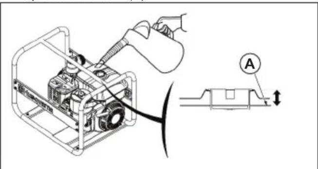
- Clean the product from fuel spillage.

CAUTION: Fuel spillage is a fire risk and can cause damage to the environment.
To fill the product with water
Before operation, it is necessary to fill the product with water to prevent damage to the product.
- Remove the pump chamber cap (A) from the pump chamber.
- Fill water to the lower surface of the discharge outlet (B).
- Install and tighten the pump chamber cap.
To start the product

CAUTION: Do not operate the product dry. Fill the product with water before operation to prevent damage to the pump seal. Refer to To fill the product with water on page 8.
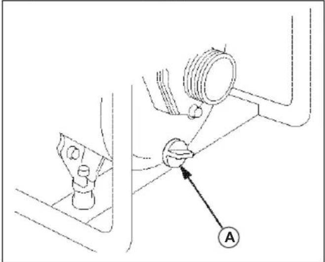
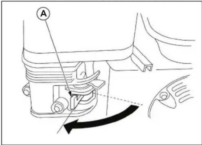
- Set the fuel valve lever (A) to the ON position.
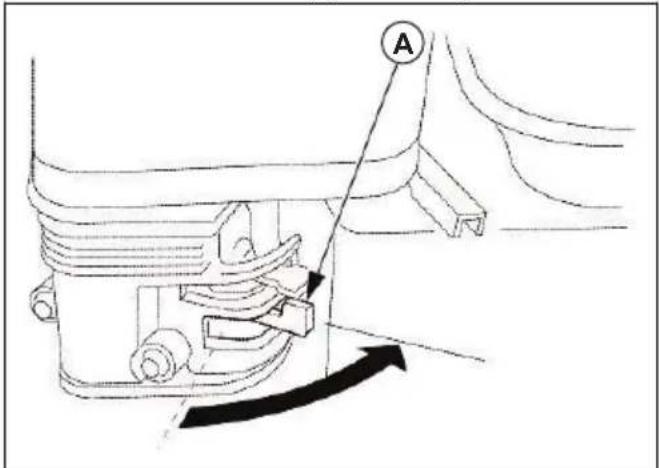
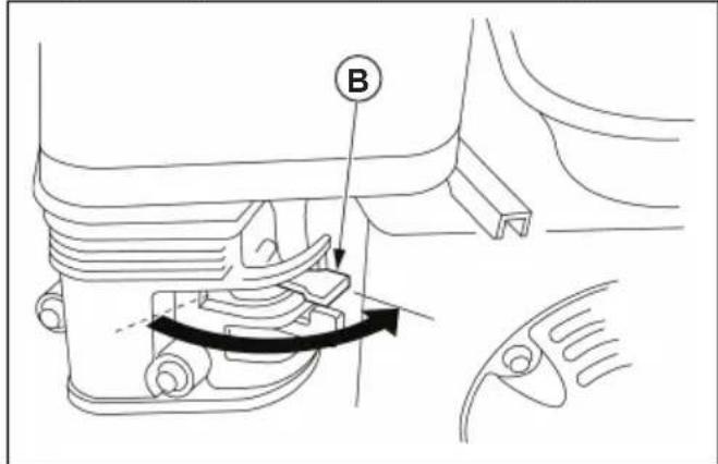
- Set the choke lever to the correct position. a) If the engine is cold, close the choke (B).

b) If the engine is warm, open the choke (B).
- Apply approximately 1/3 throttle (C).

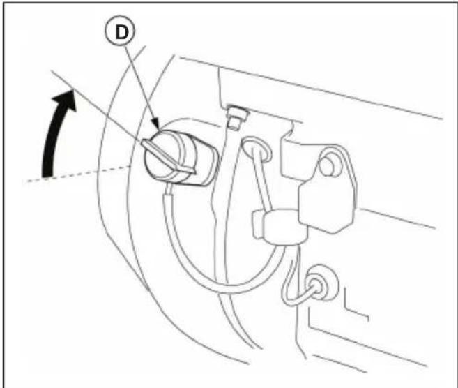
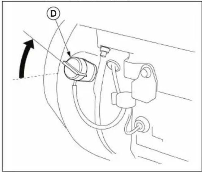
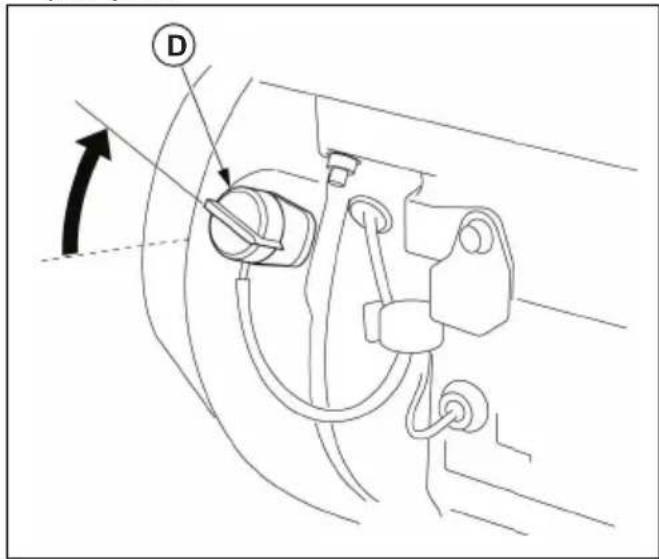
- Put the ON/OFF switch (D) to the ON position.
- Pull the starter rope handle (E) slowly until you feel resistance.
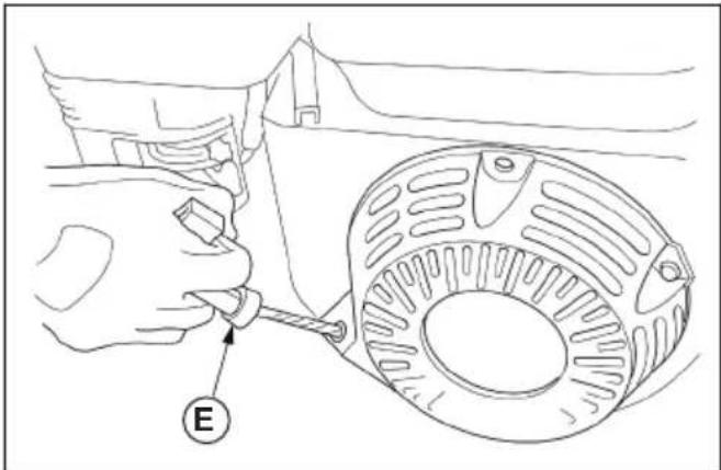
- Pull the starter rope handle quickly and with force until the engine starts.
- Move the starter rope handle back slowly into its initial position to prevent damage to the product.
- If the engine is cold, open the choke gradually as the engine becomes warm.
To set the engine speed and pump output
- Move the throttle lever fully to the left to increase the engine speed.
- Do a check of the pump output.
- Adjust the pump output with the throttle lever (A) if it is necessary.
Note: The pump output is related to the engine speed and is adjusted with the throttle lever.
a) Move the throttle lever to the left to increase the pump output.
b) Move the throttle lever to the right to decrease the pump output.
To stop the product

WARNING: If an emergency occurs, immediately set the ON/OFF switch to the OFF position to stop the engine.
- Decrease the engine speed with the throttle lever (A).
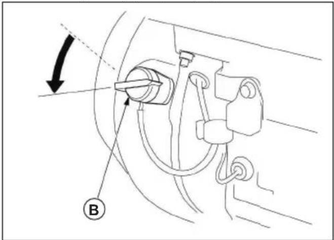
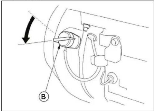
- Set the ON/OFF switch (B) to the OFF position.
- Set the fuel valve lever (C) to the OFF position.
- After the product has stopped, clean the product. Refer to To clean the product on page 13.
Maintenance
Introduction

WARNING: Read and understand the safety chapter before you do maintenance on the product.
Maintenance schedule
* Clean at a more regular interval if the product is used in conditions with much dust.
** Maintenance is only necessary if operation problems occur. Speak to an approved servicing dealer.
| Maintenance | Daily maintenance before operation | Maintenance interval in hours | |||
| 20 hours or each month | 50 hours or each 3 months | 100 hours or each 6 months | 300 hours or 1 time each year | ||
| Do a check of the engine oil level. X | |||||
| Replace the engine oil. X X | |||||
| Do a check of the air filter. X | |||||
| Clean the air filter. X* | |||||
| Do a check of the spark plug. X | |||||
| Replace the spark plug. X | |||||
| Clean the spark arrester screen (if applicable). X | |||||
| Clean the sediment cup. X | |||||
| Do a check and adjust the engine speed. X** | |||||
| Do a check and adjust the valve clearance. X** | |||||
| Clean the combustion chamber. After each 500 hours or 2 years. | years. | ||||
| Clean the fuel tank and fuel filter. X** | |||||
| Do a check of the fuel tube. After each 500 hours or 2 years. | |||||
| Do a check of the impeller and impeller clearance. X** | |||||
| Do a check of the pump inlet valve. X** | |||||
To do a check of the engine oil level

CAUTION: Do not operate the product with low engine oil level. It can cause damage to the engine.

CAUTION: Use detergent engine oil for 4-stroke engines with the viscosity range shown in the illustration.
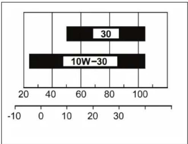
bar
| Category | Value | | -------- | ----- | | 30 | 100 | | 10W-30 | 100 |- Stop the product fully and make sure that the product is on level ground.
- Remove the oil tank cap and dipstick (A).
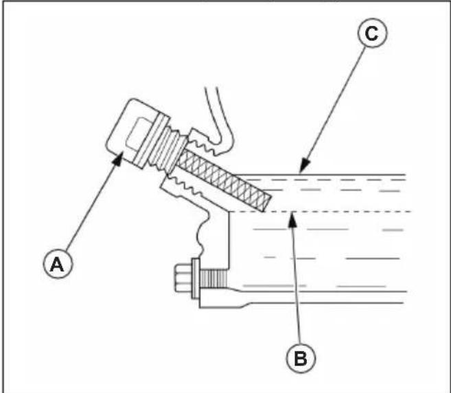
- Clean the oil from the dipstick.
- Put the dipstick back fully into the oil tank.
- Remove the dipstick.
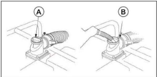
- Examine the engine oil level on the dipstick.
- If the engine oil level is low (B), fill engine oil to the edge of the oil tank hole (C).
- Do a check of the engine oil level again.
- Install the oil tank cap and dipstick.
To replace the engine oil
Note: Drain the engine oil while the engine is warm. Warm engine oil is faster to drain.

WARNING: The engine oil becomes very hot and can cause burn injuries. Let the engine become cool before you drain the engine oil.
-
Put an applicable fuel container below the drain hole on the engine.
-
Remove the oil tank cap and dipstick (A).
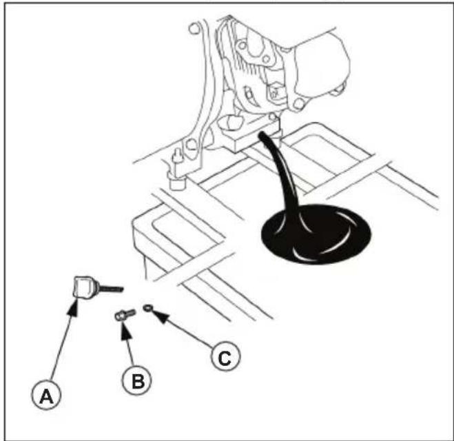
- Remove the drain plug (B) and sealing washer (C). Discard the sealing washer.
- Let the engine oil drain fully into the fuel container.
- Install a new sealing washer and the drain plug.
- Fill engine oil. Refer to To do a check of the engine oil level on page 11.
- Install the oil tank cap and dipstick and tighten it.
- Recycle the used engine oil at an approved disposal location.
To do a check of the air filter

CAUTION: Replace the air filter if it cannot be fully cleaned or if it is damaged. Do not operate the product with a damaged air filter. A damaged air filter can cause damage to the engine.
- Remove the star nut (A), the air filter cover (B), the wing nut (C) and the air filter (D).
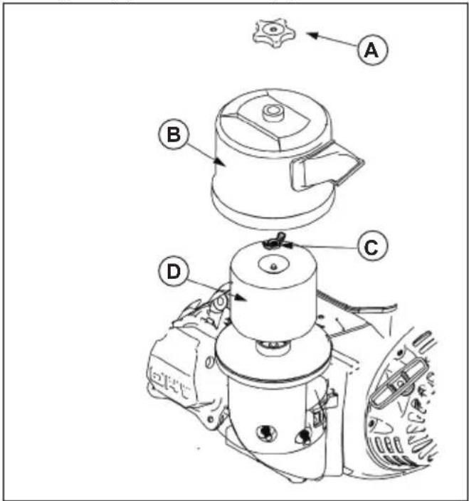
-
Examine the air filter for dirt and damage.
-
Clean the air filter if it is necessary. Do the steps that follow.
a) Clean the air filter in warm soap water.
b) Let the air filter become dry.
c) Put the air filter in engine oil. Rub the air filter to supply the engine oil equally across the air filter.
d) Compress the air filter to remove unwanted oil from the air filter.
-
Clean the area around the air filter and the air filter cover. Make sure that no unwanted particles go into the air duct that is connected to the carburetor.
-
Install the air filter, the wing nut, the air filter cover and the star nut.
To clean the product

WARNING: Let the engine become cool before you clean the product.
- Clean the product parts by hand.

CAUTION: Do not let water go into the air filter, air filter cover, the muffler or the controls. This can cause damage to the product.
-
Use a cloth to dry the surface of the product.
-
Fill the pump chamber with water. Refer to To fill the product with water on page 8.
Troubleshooting
The engine does not start
| Cause Solution | |
| The fuel valve lever is set to the OFF position. Move the fuel valve lever to the ON position. | |
| The choke is open. Close the choke. | |
| The ON/OFF switch is set to the OFF position. Set the ON/OFF switch to the ON position. | |
| There is no fuel in the fuel tank. Fill fuel. | |
| There is unsatisfactory fuel in the fuel tank. Drain the fuel tank and the carburetor. Refer to the fuel tank and carburetor on page 15. Fill with clean fuel. | |
| No fuel stabilizer has been added or the fuel tank has not been drained before storage. | |
| The spark plug is damaged. Do a check of the electrode gap or replace the spark plug. | |
| The spark plug is wet from fuel. Remove the spark plug and let it dry. Install the spark plug. | |

CAUTION: Speak to an approved servicing dealer if the problem stays.
The power of the engine is decreased
| Cause Solution | |
| The air filter is clogged. Clean or replace the air filter. | |
| The fuel tank contains bad gasoline. Drain the fuel tank and the fuel tank and carburetor. Refer to the fuel tank and carburetor on page 15. Fill with clean gasoline. | |
| No fuel stabilizer has been added or the fuel tank has not been drained before storage. | |
| The engine speed is set to low. Increase the engine speed. | |

CAUTION: Speak to an approved servicing dealer if the problem stays.
There is no pump output or the pump output is decreased
| Cause Solution | |
| The location of the product is incorrect. Refer to | Installation on page 7. |
| There is no water in the pump chamber. Refer to | To fill the product with water on page 8 |
| The suction hose is damaged. Replace the suction hose. | |
| The strainer is above the water surface. Put the strainer fully into water. | |
| There is an air leakage at the hose connector. Replace the sealing washer if it is damaged. Tighten the hose connector and hose clamp. | |
| The strainer is clogged. Clean the strainer. | |
| The strainer is damaged. Replace the strainer. | |
| The level difference of the hoses is too high. Change the location of the product and/or the hoses. | |
| The hoses are damaged or too long. The hoses has an incorrect diameter. | Select the correct hose for the operation. Refer to To select the correct hoses for the operation on page 6. |
| The power of the engine is decreased. Refer to | The power of the engine is decreased on page 14. |
Transportation and storage
Transportation
- Let the product become cool for a minimum of 15 minutes before transportation.
- Keep the product on a level surface during transportation to prevent fuel leakage.
- Make sure that the fuel valve lever is in the OFF position.
To prepare the product for short-term storage
The instructions that follow are applicable for a storage period of 30-90 days.
- Stop the product fully. Refer to To stop the product on page 10.
- Drain the pump chamber.
a) Remove the drain plug (A).
b) Flush the pump chamber with clean water.
c) Let the water drain from the pump chamber.
d) Install the drain plug.
- Clean the product. Refer to page 13. To clean the product on
- Lubricate the controls with a silicone spray lubricant.
- Examine the product for corrosion. Speak to a servicing dealer if it is necessary.
- Add the fuel stabilizer to the fuel tank to prevent deterioration. Refer to To add a fuel stabilizer to the fuel on page 15.
- Put a dust cover on the product for protection.
- Put the product in a location with a good airflow and away from flames and sparks.
- If it is possible, do not put the product in a location with high humidity.
To add a fuel stabilizer to the fuel
To keep the fuel in good condition for a period of 3 months, it is necessary to add a fuel stabilizer.
- Put the fuel stabilizer in a fuel container with fresh fuel.
- Fill the fresh fuel with fuel stabilizer into the fuel tank of the product. Refer to To fill fuel on page 8.
- Fill the pump chamber with water. Refer to To fill the product with water on page 8
- Start the engine and let the product operate for 10 minutes. This is to make sure that the fuel with the fuel stabilizer has replaced the fuel without a fuel stabilizer.
- Stop the engine and move the fuel valve lever to the OFF position. Refer to To stop the product on page 10
- Drain the water from the pump chamber.
To prepare your product for long-term storage
The instructions that follow are applicable to a storage period longer than 90 days.
- Do the steps given in To prepare the product for short-term storage on page 14.
- Replace the engine oil. Refer to To replace the engine oil on page 12.
- Apply oil to the cylinder. Refer to To apply oil to the cylinder on page 16.
- Drain the fuel tank and carburetor. Refer to To drain the fuel tank and carburetor on page 15.
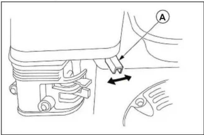
To drain the fuel tank and carburetor
- Put an applicable fuel container below the carburetor. Use a funnel to prevent fuel leakage.
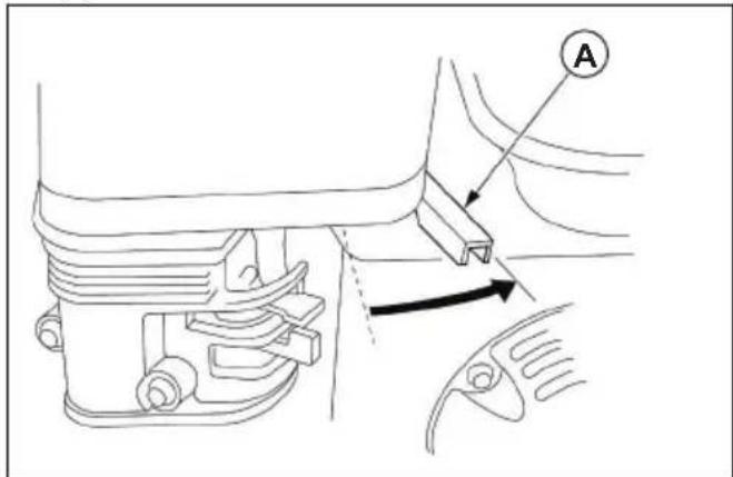
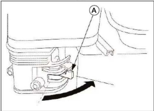
- Move the fuel valve lever (A) to the OFF position.
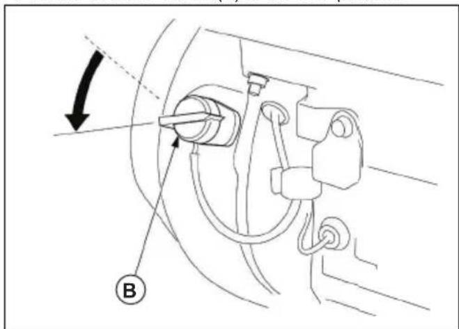
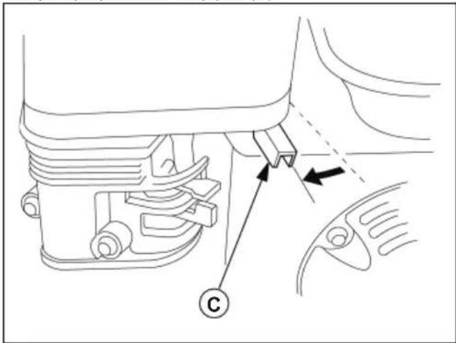
- Turn the carburetor drain bolt (B) 1-2 turns counterclockwise.
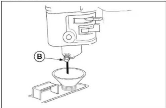
- Let the fuel drain from the carburetor.
- Tighten the carburetor drain plug.
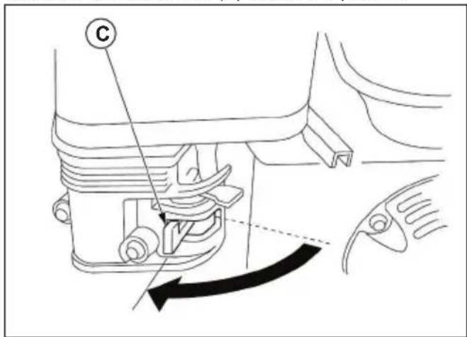
-
Remove the sediment cup.
-
Move the fuel valve lever (A) to the ON position.
- Let the fuel drain from the fuel tank.
To apply oil to the cylinder
-
Remove the spark plug.
-
Put approximately 5 cl of clean engine oil into the cylinder.
-
Pull the starter rope handle approximately 5 times to apply the oil equally in the cylinder.
- Install the spark plug.
- Pull the starter rope handle slowly. Pull until you feel resistance and the notch on the pulley aligns with the hole at the top of the starter cover (A).
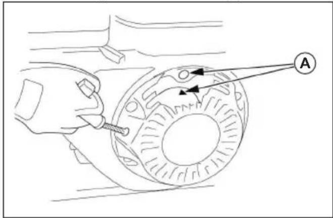
- Slowly move the starter rope handle back to its initial position.
Technical data
Technical data
| Husqvarna W50P Husqvarna W80P | ||
| Inlet/outlet dimension, mm 50 80 | ||
| Total level difference, m 28 28 | ||
| Level difference for the suction hose, m | 7 | 7 |
| Engine model 168FB 168FB | ||
| Maximum discharge capacity, m/h 32 54 | ||
| Fuel tank capacity, l 3.6 3.6 | ||
| Net weight/Gross weight, kg 25/27 28/30 | ||
| Oil tank capacity, l 0.6 0.6 | ||
| Type Gasoline Gasoline | ||
| Measured Sound Power Level, LWA dB (A) | 108 dB (A) | 108 dB(A) |
| Guaranteed Sound Power Level, LWA dB (A) | 108 dB (A) | 108 dB (A) |
EC Declaration of Conformity
EC Declaration of conformity
For the following machinery
• Product name: Water Pump
• Model No.: W50P, W80P
- Function: Pump units
- Serial No.: 1708000024, 1708000010 and onwards
is herewith confirmed to fulfill all the relevant provisions of
• Machinery Directive (2006/42/EC)
- Restriction of Hazardous Substances (RoHS) Directive (2011/65/EU)
• Electromagnetic Compatibility Directive (2014/30/EU)
- Noise Emission Directive by equipment for use outdoors (2000/14/EC + 2005/88/EC)
- Conformity Assessment Procedure (2000/14/EC), amended by 2005/88/EC- Annex VI
and the following harmonized standard have been complied with
• EN 809:1998+A1; EN 809:1998+A1/AC, EN 61000-6-1:2007; EN 55012:2007+A1
Weima, Notified Body for Machinery (notified under 0197), Weima lab., carried out the noise certification. For information about noise emissions, refer to Technical data on page 16.
Huskvarna, 2020-06-10
Δdot du
Claes Losdal, Development Manager/Garden Products (Authorized representative for Husqvarna AB and responsible for technical documentation).
Съдържание
Въведение.... 18
Безопасност....21
Монтаж....23
Инсталиране....24
Операция.... 24
Безопасност
Дефиниции за безопасност
natural_image
Technical line drawing of a mechanical assembly with no visible text or symbolsТехнически данни
Технически характеристики
Bezpečnost
- Uved'te vypínač (D) do polohy zapnuto.
natural_image
Line drawing of a hand using a tool to adjust or install a mechanical component, with no visible text or symbols.- Nastavte vypínač (B) do polohy vypnuto.
natural_image
Technical line drawing of a mechanical assembly with a labeled component (A), no readable text or symbols present.Ασφάλεια
natural_image
Line drawing of a hand holding a tool next to a car wheel (no text or symbols)Τεχνικά στοιχεία
Τεχνικά στοιχεία
Seguridad
natural_image
Line drawing of a hand using a tool to adjust or install a mechanical component, with no visible text or symbols.Sécurité
Biztonság
natural_image
Line drawing of a hand holding a tool next to a car wheel (no text or symbols)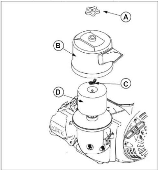
Sicurezza
natural_image
Technical line drawing of a mechanical assembly with labeled component (no text or symbols)natural_image
Line drawing of a hand holding a tool next to a mechanical component, no text or symbols presentBezpieczeństwo
natural_image
Technical line drawing of a mechanical assembly with no visible text or symbolsnatural_image
Line drawing of a hand using a tool to adjust or install a mechanical component, with no visible text or symbols.Segurança
natural_image
Technical line drawing of a mechanical component with arrows indicating motion or assembly (no text or symbols)Siguranță
natural_image
Line drawing of a hand using a tool to adjust or install a mechanical component, with no visible text or symbols.Bezpečnost'
- Aplikujte približne 1/3 plynu (C).
- Prepnite spínač zapnutia/vypnutia (D) do zapnutej polohy ON.
- Prepnite spínač zapnutia/vypnutia (B) do polohy OFF (Vyp.).
- Nechajte palivo vytiect' z palivovej nádrže.
Güvenlik
Güvenlik tanımları
natural_image
Technical line drawing of a mechanical component with arrows indicating motion or assembly (no text or symbols)2020-11-11

- Introduction
- Product description
- Intended use
- Symbols on the product
- Type plate
- Safety
- Safety definitions
- General safety instructions
- Safety instructions for operation
- Fuel safety
- Exhaust fumes safety
- Safety instructions for maintenance
- Assembly
- To select the correct hoses for the operation
- To install the suction hose to the product
- To install the discharge hose
- Installation
- To install the product
- Operation
- To do before you operate the product
- To fill fuel
- To fill the product with water
- To start the product
- To set the engine speed and pump output
- To stop the product
- Maintenance
- Maintenance schedule
- To do a check of the engine oil level
- To replace the engine oil
- To do a check of the air filter
- To clean the product
- Troubleshooting
- The power of the engine is decreased
- There is no pump output or the pump output is decreased
- Transportation and storage
- Transportation
- To prepare the product for short-term storage
- To add a fuel stabilizer to the fuel
- To prepare your product for long-term storage
- To drain the fuel tank and carburetor
- To apply oil to the cylinder
- Technical data
- EC Declaration of Conformity
- Съдържание
- Безопасност
- Дефиниции за безопасност
- Технически данни
- Bezpečnost
- Ασφάλεια
- Τεχνικά στοιχεία
- Seguridad
- Sécurité
- Biztonság
- Sicurezza
- Bezpieczeństwo
- Segurança
- Siguranță
- Bezpečnost'
- Güvenlik
- Güvenlik tanımları
Brand : HUSQVARNA
Model : W 50P
Category : Pump