
W 100D - Pump HUSQVARNA - Free user manual and instructions
Find the device manual for free W 100D HUSQVARNA in PDF.


| Product Type | Water Pump |
| Brand | Husqvarna |
| Model | W 100D |
| Inlet / Outlet Size | 100 mm (4 inches) |
| Total Lift | 25 m |
| Suction Lift | 5 m |
| Max Discharge Capacity | 92 m³/h |
| Max Power | 6.3 kW |
| Engine Model | 186FB (Diesel) |
| Fuel Tank Capacity | 5.5 L |
| Weight | 69 kg |
| Pumpable Liquid | Fresh water only (not for human consumption) |
| Priming | Manual fill before start |
| Start System | Recoil starter with decompression lever |
| Fuel Type | Diesel (cetane 45 or higher) |
| Oil Capacity | Approx. 1.1 L (SAE 10W-30 recommended) |
| Maintenance Interval | Oil change every 50 hours (first), air filter every 50 hours |
| Safety Features | Carbon monoxide warning, hot surface caution, fuel handling warnings |
| Included Accessories | Strainer, priming filler cap, hose clamps |
Frequently Asked Questions - W 100D HUSQVARNA
User questions about W 100D HUSQVARNA
0 question about this device. Answer the ones you know or ask your own.
Ask a new question about this device
Download the instructions for your Pump in PDF format for free! Find your manual W 100D - HUSQVARNA and take your electronic device back in hand. On this page are published all the documents necessary for the use of your device. W 100D by HUSQVARNA.
USER MANUAL W 100D HUSQVARNA
natural_image
Close-up of a red car hood with a 3D car logo on the front (no visible text or symbols)natural_image
Simple line drawing of an open book enclosed in a circle (no text or symbols)Thank you for choosing a Husqvarna waterpump.
This manual is to help you get the best results from your new water pump and to operate it safely.
As you read this manual, you will find information preceded by a NOTICE symbol. That information is intended to help you avoid damage to your water pump, other property, or the environment.
ABOUT SAFETY
Your safety and the safety of others are very important. And using this water pump safely is an important responsibility.
To help you to use the water pump safely, we have provided operating procedures and other information on labels and in this manual. This information alerts you to potential hazards that could hurt you or others.
Of course, it is not practical or possible to warn you about all the hazards associated with operating or maintaining a water pump. You must use your own good judgment.
You will find important safety information in a variety of forms, including:
- Safety Labels- on the pump.
- Safety Messages- preceded by a safety alert symbol and one of three signal words, DANGER, WARNING, or CAUTION.
These signal words mean:
| WARNING SYMBOLS AND DEFINITIONS | |
| This is the safety alert symbol. It is used to alert you to potential personal injury hazards. Obey all safety messages that follow this symbol to avoid possible injury or death. | |
| DANGER | Indicates a hazardous situation which, if not avoided, will result in death or serious injury. |
| WARNING | Indicates a hazardous situation which, if not avoided, could result in death or serious injury. |
| CAUTION | Indicates a hazardous situation which, if not avoided, could result in minor or moderate injury. |
| NOTICECAUTION | Addresses practices not related to personal injury. |
CONTENTS
PUMP SAFETY 5
IMPORTANT SAFETY INFORMATION .... 5
SAFETY LABEL 7
CONTROLS & FEATURES 8
Name Plate 9
BEFORE OPERATION....10
READY TO GET START? 10
Check the General Condition of the Pump 11
Check the Suction and Discharge Hoses 12
Check the Engine....12
OPERATION 13
SAFE OPERATING PRECAUTIONS 13
PUMP PLACEMENT 14
SUCTION HOSE INSTALLATION.... 15
DISCHARGE HOSE INSTALLATION 16
PRIMING THE PUMP 17
STARTING THE ENGINE 18
STOPPING THE ENGINE....20
MAINTENANCE 21
THE IMPORTANCE OF MAINTENANCE 21
MAINTENANCE SAFETY 22
MAINTENANCE SCHEDULE....23
REFUELING....24
FUEL RECOMMENDATIONS 25
ENGINE OIL LEVEL CHECK 26
ENGINE OIL CHANGE 27
CLEAN/INSPECT ENGINE OIL FILTER 27
ENGINE OIL RECOMMENDATION 28
STORAGE 30
STORAGE PREPARATION 30
TRANSPORTING 31
TROUBLE SHOOTING 32
ENGINE DOES NOT START 32
WHITE OR BLACK EXHAUST SMOKE 32
NO PUMP OUTPUT 33
LOW PUMP OUTPUT 33
TECHNICAL INFORMATION 34
SPECIFICATION....34
PUMP SAFETY
IMPORTANT SAFETY INFORMATION
Husqvarna W 100D pumps are designed to pump only fresh water that is not intended for human consumption; other uses can result in injury to the operator or damage to the pump and other property.
Most injuries or property damage can be prevented if you follow all instructions in this manual and on the pump. The most common hazards are discussed below, along with the best way to protect yourself and others.
Operator Responsibility
It is the operator's responsibility to provide the necessary safeguards to protect people and property. Know how to stop the pump quickly in case of emergency. If you leave the pump for any reason, always turn the engine off. Understand the use of all controls and connections.
Be sure that anyone who operates the pump receives proper instruction. Do not let children operate the pump. Keep children and pets away from the area of operation.
Pump Operation
Pump only fresh water that is not intended for human consumption. Pumping flammable liquids, such as gasoline or fuel oils, can result in a fire or explosion, causing serious injury. Pumping sea water, beverages, acids, chemical solutions, or any other liquid that promotes corrosion can damage the pump.
Refuel With Care
Diesel is extremely flammable.
Refuel outdoors, in a well-ventilated area, with the engine stopped and the pump on a level surface. Do not fill the fuel tank above the fuel strainer shoulder. Never smoke near diesel, and keep other flames and sparks away. Always store diesel in an approved container. Make sure that any spilled fuel has been wiped up before starting the engine.
Hot Exhaust
The muffler becomes very hot during operation and remains hot for a while after stopping the engine. Be careful not to touch the muffler while it is hot. Let the engine cool before transporting the pump or storing it indoors.
To prevent fire hazards, keep the pump at least 3 feet (1 meter) away from building walls and other equipment during operation. Do not place flammable objects close to the engine.
Carbon Monoxide Hazard
Your water pump's exhaust contains poisonous carbon monoxide gas, which you cannot see or smell.
Breathing carbon monoxide can KILL YOU IN MINUTES.
For your safety:
- Do not start or operate the engine in any closed or partially enclosed area, such as a garage.
- Never run the water pump in a closed or even partially closed area where people or pets may be present.
- Never operate the water pump near open doors, windows, or vents.
- Get fresh air and seek medical attention immediately if you suspect you have inhaled carbon monoxide.
Early symptoms of carbon monoxide exposure include headache, fatigue, shortness of breath, nausea, and dizziness. Continued exposure to carbon monoxide can cause loss of muscular coordination, loss of consciousness, and then death.
SAFETY LABEL
The labels shown here contain important safety information. Please read them carefully.

WARNING! Careless or incorrect use can result in serious or fatal injury to the operator or others.

Please read the operator's manual carefully and make sure you understand the instructions before using the machine.

Use a helmet with hearing protector

Operation of this equipment may create sparks.

WARNING marking concerning Risk of Respiratory Injury. Operate engine OUTSIDE and far away

Keep hands away from the rolling part.


Be care of hot surface

WARNING marking concerning Risk of Fire while handling fuel. Do not smoke while handling fuel.
ATTENTION
Must fill enough water into the pump before starting.
The remainder water in pump with high temperature is dangerous for you. Please shut down the engine after use.
MAINTAIN AIR CLEANER
Clean up the air cleaner core once every 50 hours (every 10 hours in unusually dusty circumstances). Clean the foam and paper element filter.
WARNING
This internal combustion engine produces exhaust that contains carbon monoxide, a poisonous gas. Never use the engine in a confined or closed area. Operate in a well ventilated area.
△OPERATION NOTES
- Prior to operation please read the user's manual carefully
- This engine is shipped without oil in the crankcase, BEFORE USE, fill the crankcase with the proper engine oil. Consult the owners manual for oil specification and fill instructions.
- Check for fuel spills or leakage. DO NOT start the engine if fuel is present outside the fueltank.

ATTENTION
IF THE OIL LEVEL IS LOW, FILL OIL TO THE UPPER LEVEL.
CONTROLS & FEATURES
W 100D

CONTROLS & FEATURES
NAME PLATE

natural_image
Technical line drawing of a mechanical device labeled 'Husqvarna' (no other text or symbols)
Husqvarna
Water pump
Prod. year 2023
| Serial No | 0000000000 |
| Article no. | 967 63 92-01 |
| Model | W 100D |
| Inlet / Outlet size | 100 mm |
| Lift | 25 m |
| Suction | 5 m |
| Engine model | 186FB |
| Max DischargeCapacity (m3/h) | 92 |
| Max Power | 6.3kW |
| Fuel tank capacity | 5.5 L |
| Weight | 69 kg |
HUSQVARNA AB
SE-561 82 HUSKVARNA
SWEDEN
BEFORE OPERATION
READY TO GET START
Your safety is your responsibility. A little time spent in preparation will significantly reduce your risk of injury.
Knowledge
Read and understand this manual. Know what the controls do and how to operate them.
Familiarize yourself with the pump and its operation before you begin pumping. Know what to do in case of emergencies.
Be sure of what you are pumping. This pump is designed to pump only fresh water that is not intended for human consumption.
For your safety, and to maximize the service life of your equipment, it is very important to take a few moments before you operate the pump to check its condition. Be sure to take care of any problem you find, or have your servicing dealer correct it, before you operate the pump.
WARNING
Improperly maintaining this pump, or failing to correct a problem before operation, could cause a malfunction in which you could be seriously injured.
Always perform a pre-operation inspection before each operation, and correct any problem.
To prevent a possible fire, keep the pump at least 3 feet (1 meter) away from building walls and other equipment during operation. Do not place flammable objects close to the engine.
Before beginning your pre-operation checks, be sure the pump is on a level surface and the stop switch is in the OFF position.
Check the General Condition of the Pump
- Before each use, look around and underneath the engine for signs of oil or diesel leaks.
- Remove any excessive dirt or debris, especially around the engine muffler and recoil starter.
- Look for signs of damage.
- Check that all nuts, bolts, screws, hose connectors and clamps are tightened.
Check the Suction and Discharge Hoses
- Check the general condition of the hoses. Be sure the hoses are in serviceable condition before connecting them to the pump. Remember that the suction hose must be reinforced construction to prevent hose collapse.
- Check that the sealing washer in the suction hose connector is in good condition.
- Check that the hose connectors and clamps are securely installed.
- Check that the strainer is in good condition and is installed on the suction hose.
Check the Engine
- Before each use, look around and underneath the engine for signs of oil or diesel leaks.
- Check the engine oil level. Running the engine with a low oil level can cause engine damage.
- Check the air filter. A dirty air filter will restrict air flow to the carburetor, reducing engine and pump performance.
- Check the fuel level. Starting with a full tank will help to eliminate or reduce operating interruptions for refueling.
OPERATION
SAFE OPERATING PRECAUTIONS
To safely realize the full potential of this pump, you need a complete understanding of its operation and a certain amount of practice with its controls.
Before operating the pump for the first time, please review the IMPORTANT SAFETY INFORMATION on page 5 and the chapter titled BEFORE OPERATION.
For your safety, avoid starting or operating the engine in an enclosed area, such as a garage. Your engine's exhaust contains poisonous carbon monoxide gas that can collect rapidly in an enclosed area and cause illness or death.
WARNING
Exhaust contains poisonous carbon monoxide gas that can build up to dangerous levels in closed areas. Breathing carbon monoxide can cause unconsciousness or death.
Never run the engine in a closed, or even partly closed area where people may be present.
Pump only fresh water that is not intended for human consumption. Pumping flammable liquids, such as diesel or fuel oils, can result in a fire or explosion, causing serious injury. Pumping sea water, beverages, acids, chemical solutions, or any other liquid that promotes corrosion can damage the pump.
PUMP PLACEMENT
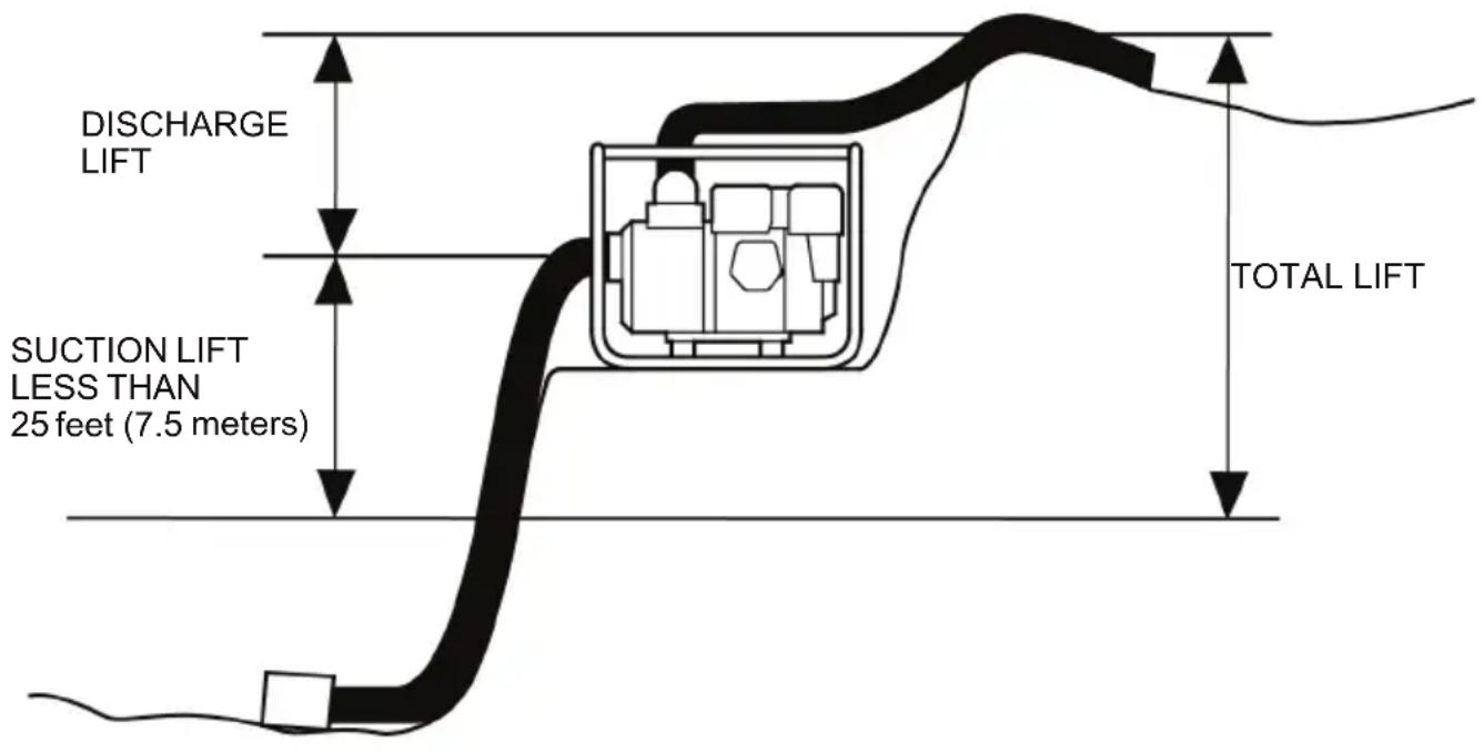
For best pump performance, place the pump on a firm, level surface, and near the water level, and use hoses that are no longer than necessary. That will enable the pump to produce the greatest output with the least self-priming time.
As lift (pumping height) increases, pump output decreases. The length, type, and size of the suction and discharge hoses can also significantly affect pump output.
Discharge lift capability is always greater than suction lift capability, so it is important for suction lift to be the shorter part of total lift. The maximum available suction lift will vary based on the operating conditions. However, the suction lift can never exceed 25 feet (7.5 meters) and should always be kept as low as possible.
Minimizing suction lift (placing the pump near the water level) is also very important for reducing self-priming time. Self-priming time is the time it takes the pump to bring water the distance of the suction lift during initial operation.
SUCTION HOSE INSTALLATION
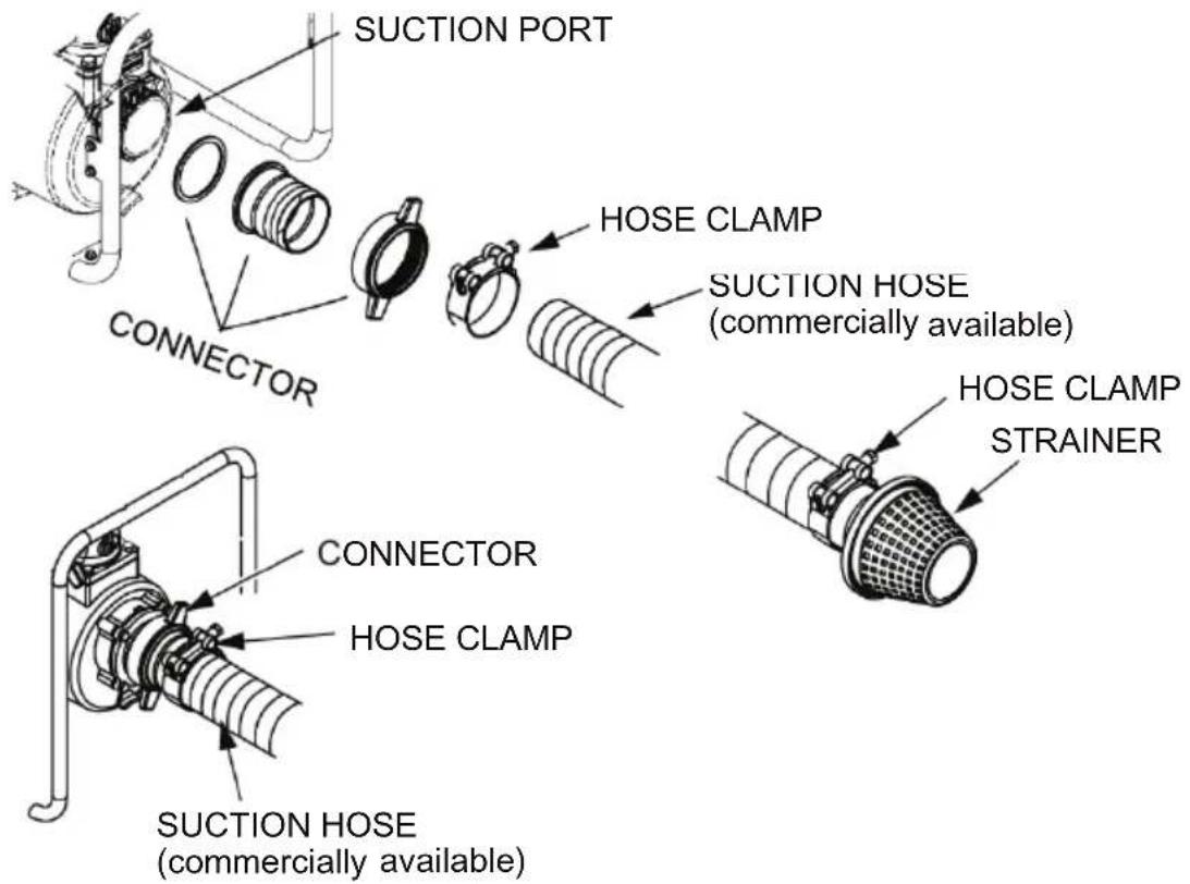
Use a commercially available hose and hose connector with the hose clamp provided with the pump (if necessary). Most hoses come with the connectors already installed. The suction hose must be reinforced with a noncollapsible wall or braided wire construction and cannot contain any perforations.
Do not use a hose smaller than the pump's suction port size. Minimum hose size: W 100D=4 inch (100 mm)
The suction hose should be no longer than necessary. Pump performance is best when the pump is near the water level and the hoses are short.
Use a hose clamp to securely fasten the hose connector to the suction hose in order to prevent air leakage and loss of suction. Verify that the hose connector sealing washer is in good condition.
Install the strainer (provided with the pump) one with equivalent hole sizes on the other end of the suction hose, and secure it with a hose clamp. The strainer will help to prevent the pump from becoming clogged or damaged by debris.
Never operate the pump without the strainer installed.
Securely tighten the hose connector on the pump suction port.
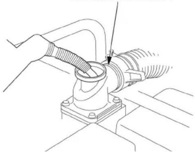
DISCHARGE HOSE INSTALLATION
Use a commercially available hose and hose connector with the hose clamp provided with the pump (if necessary).
It is best to use a short, large-diameter hose, because that will reduce fluid friction and improve pump output. A long or small-diameter hose will increase fluid friction and reduce pump output.
Tighten the hose clamp securely to prevent the discharge hose from disconnecting under pressure.

DISCHARGE HOSE (commercially available)
PRIMING THE PUMP
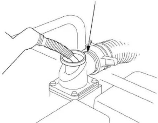
Before starting the engine, remove the filler cap from the pump chamber. Fill the pump chamber to the undersurface of the discharge port with water. Reinstall the filler cap and tighten it securely.
NOTICE
Operating the pump dry will destroy the pump seal. If the pump has been operated dry, stop the engine immediately, and allow the pump to cool before priming.

If the discharge hose must run across a roadway, the hose should cross the roadway perpendicular to traffic flow. Also, heavy boards should be placed next to the hose so the motor vehicle weight does not shut off the discharge as vehicles cross over the hose.
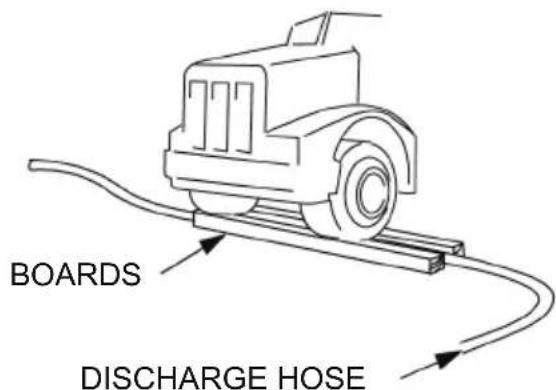
Driving over a discharge hose while the pump is running, or even possibly when the pump is stopped, may cause pump case failure.
STARTING THE ENGINE
- Fill fuel and engine oil.
- Prime the pump.
- Open the fuel cock from S(shut) to O(open).

natural_image
Technical schematic of a mechanical assembly with pipes and components (no visible text or labels)- Adjust governor control handle bar to position of "START" and tighten it.

- Press down decompression lever, and pull recoil starter.
a. Pull recoil starter until the resistance is felt, and then return the hand back to previous position.
b. Push the decompression lever down and release it. After the start of diesel engine, decompression lever will return to its previous position automatically.
c. Start: pull the handle starter all the way out with a strong and and even motion. Use two hands if necessary.
d. If the engine is not started, start from action “a” and repeat it again. After start, return recoil handle bar back lightly, and do not let it spring back suddenly.
STOPPING THE ENGINE
Follow these steps to shut down the engine,
- Untighten the knob, release it, will return to "STOP" position. The engine been shut down.
SPEED CONTROL KNOB

- Turn the fuel cock to the OFF position, from O(open) to S(shut).

MAINTENANCE
THE IMPORTANCE OF MAINTENANCE
Good maintenance is essential for safe, economical, and trouble-free operation. It will also help reduce air pollution.
WARNING
Improperly maintaining this pump, or failure to correct a problem before operation, can cause a malfunction in which you can be seriously hurt or killed.
Always follow the inspection and maintenance recommendations and schedules in this owner's manual.
To help you properly care for your pump, the following pages include a maintenance schedule, routine inspection procedures, and simple maintenance procedures using basic hand tools. Other service tasks that are more difficult, or require special tools, are best handled by professionals and are normally performed by the Husqvarna dealers.
The maintenance schedule applies to normal operating conditions. If you operate your pump under severe conditions, such as sustained high-load or high-ambient temperature operation, or use in unusually wet or dusty conditions, consult your servicing dealer for recommendations applicable to your individual needs and use.
Remember that your servicing dealer knows your pump best and is fully equipped to maintain and repair it.
MAINTENANCE SAFETY
Daily and periodic maintenance is important to keep the engine in good operating condition. The following is a summary of maintenance items by periodic maintenance intervals. Periodic maintenance intervals vary depending on engine application, loads, diesel fuel and engine oil used and are hard to establish definitively. The following should be treated only as a general guideline.
MAINTENANCE SCHEDULE
o: Check : Replace
| System Check Item | Periodic Maintenance Interval | ||||
| Daily | Every 50 hours | Every 200 hours | Every 400 hours | ||
| Air Intake Clean | or Replace Air Cleaner Element – May Need More Frequent Service in Dusty Conditions | o | ★ | ||
| Engine Oil Check | Engine Oil Level & Add Engine Oil As Necessary | o | |||
| Drain and Refill Engine Oil | ★1st time | ★2nd time | |||
| Clean Engine Oil Filter – Replace If Damaged | ★2nd & after | ||||
| Check for Engine Oil Leakage o | before & after operation | ||||
| Engine Speed Control | Check for Proper Operation Verify Adjustment | o1st time | o2nd & after | ||
| Fuel Check Fuel | Tank Level & Add Fuel As Necessary | o before operation | |||
| Drain & Clean Fuel Tank o | |||||
| Clean Inlet Fuel Screen o | |||||
| Replace Outlet Filter o | ★ | ||||
| Check for Fuel Leakage | o before & after operation | ||||
(1) Service more frequently when used in dusty areas.
(2) These items should be serviced by your local dealer, unless you have the proper tools and are mechanically proficient.
REFUELING
With the engine stopped and on a level surface, remove the fuel tank cap and check the fuel level. Refill the tank if the fuel level is low.
WARNING
Diesel is highly flammable and explosive.
You can be burned or seriously injured when handling fuel.
- Stop the engine and keep heat, sparks, and flame away.
- Handle fuel only outdoors.
- Wipe up spills immediately.

Refuel in a well-ventilated area before starting the engine. If the engine has been running, allow it to cool. Refuel carefully to avoid spilling fuel. Do not fill the fuel tank completely. Fill tank to approximately 1 inch (25 mm) below the top of the fuel tank to allow for fuel expansion. If may be necessary to lower the fuel level depending on operating conditions. After refueling, tighten the fuel tank cap securely.
Never refuel the engine inside a building where gasoline fumes may reach flames or sparks. Keep gasoline away from appliance pilot lights, barbecues, electric appliances, power tools, etc.
Spilled fuel is not only a fire hazard, it causes environmental damage. Wipe up spills immediately.
NOTICE
Fuel can damage paint and plastic. Be careful not to spill fuel when filling your fuel tank. Damage caused by spilled fuel is not covered under warranty.
FUEL RECOMMENDATIONS
This engine is certified to operate on diesel with a pump cetane number should be equal to 45 or higher.
| Diesel Fuel Specification | Location |
| No. 2-D, No. 1-D, ASTM D975-94 | USA |
| EN590:96 | European Union |
| ISO 8217 DMX | International |
| BS 2869-A1 or A2 | United Kingdom |
| JIS K2204 Grade No.2 | Japan |
| KSM-2610 | Korea |
| GB252 | China |
ENGINE OIL LEVEL CHECK
Check the engine oil level with the engine stopped and in a level position.
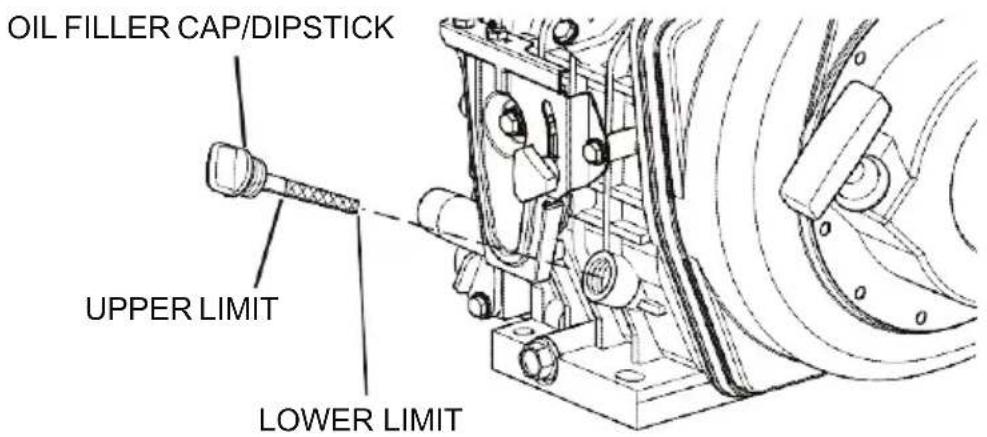
- Remove the oil filler cap/dipstick from either location and wipe it clean.
- Fully insert the oil filler cap/dipstick but do not screw in.
- Remove oil cap/dipstick. The oil should between upper and lower line on the oil filler cap/dipstick.
- Screw in the oil filler cap/dipstick securely.
NOTICE
Running the engine with a low oil level can cause engine damage.
ENGINE OIL CHANGE
The engine oil on a new engine becomes contaminated from the initial break-in in internal parts. The initial 50 hours oil change and filter cleaning is very important.
Drain the used oil while the engine is warm. Warm oil drains quickly and completely.
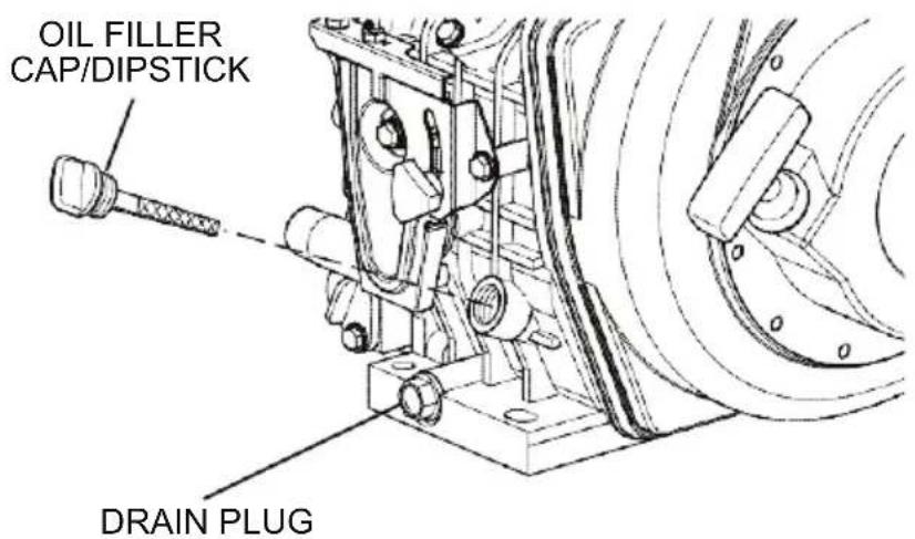
- Position a container under the engine to collect waste oil.
- Remove the drain plug located on the bottom of the cylinder block. Allow oil to drain.
- After all oil has been drained from the engine, install the drain plug and tighten.
- Dispose of used oil properly.
CLEAN/INSPECT ENGINE OIL FILTER
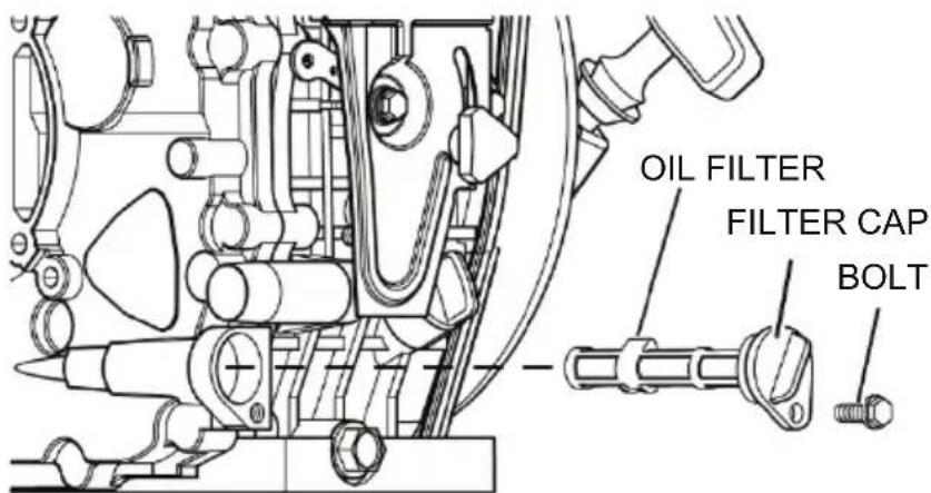
Clean / inspect the engine oil filter as follow:
- Remove the oil filter retaining bolt.
- Pull the oil filter cap out and remove the oil filter.
- Clean the oil filter or replace if damaged.
- Install the oil filter.
- Make sure the oil filter cap is fully seated.
- Install and tighten the oil filter retaining bolt.
ENGINE OIL RECOMMENDATION
Select the appropriate engine oil viscosity based on the ambient temperature and use the SAE Service Grade Viscosity.
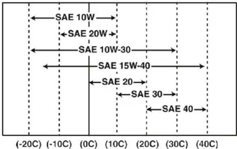
SAE 10W-30 is recommended for general use. Other viscosities shown in the chart may be used when the average temperature in your area is within the recommended range.
AIR FILTER CLEANING
The engine performance is adversely affected when the air filter element is clogged with dust. Be sure to clean the air filter element periodically.
Blow air through elements using 0.29 to 0.49Mpa (3.0 5.0kgf/cm²) air to remove the particulates. Use lowest possible air pressure to remove the dust without damaging the element.
If either element damaged replace it.

STORAGE
STORAGE PREPARATION
Proper storage preparation is essential for keeping your pump trouble-free and looking good.
- Wash the engine and pump.
- Recoil start diesel engine,
(a) Set the decompression lever down and hold it while slowly pulling the recoil starter 2 or 3 times. Do not start the engine.
(b) Pull the decompression lever up. Pull the recoil starter recoil starter slowly and stop when there is resistance. This procedure closes the intake and exhaust valves in the compression position and prevent rust.
-
Remove the pump drain plug, and flush the pump with clean, fresh water. Allow the water to drain from the pump chamber, and then reinstall the drain plug.
-
After the pump is clean and dry, touch up any damaged paint, and coat areas that may rust with a light film of oil.

TRANSPORTING
If the pump has been running, allow the engine to cool for at least 15 minutes before loading the pump on the transport vehicle. A hot engine and exhaust system can burn you and can ignite some materials.
Keep the pump level when transporting to reduce the possibility of fuel leakage. Move the fuel cock to the OFF position.
TROUBLE SHOOTING
Engine Does Not Start
| SYMPTOM | PROBABLE CAUSE | ACTION |
| Starter motor operates but engine does not start | No diesel fuel | Refuel fuel system |
| Improper diesel fuel | Replace with recommended diesel fuel | |
| Clogged fuel filter | Replace fuel filter | |
| Poor fuel injection | Consult local dealer | |
| Compressed air leakage from intake / exhaust valves | ||
| Faulty engine stop solenoid (if equipped) | ||
| Engine cannot be manually turned | Inner parts seized or damaged | Consult local dealer |
White or Black Exhaust Smoke
| SYMPTOM | PROBABLE CAUSE | ACTION |
| Black exhaust smoke | Engine overloaded | Reduce load |
| Clogged air cleaner element | Clean element or replace | |
| Improper diesel fuel | Replace with recommended diesel fuel | |
| Faulty spraying of fuel injection | Consult local dealer | |
| Excessive intake / exhaust valve clearance | ||
| White exhaust smoke | Improper diesel fuel | Replace with recommended diesel fuel |
| Faulty spray pattern of fuel injection | Consult local dealer | |
| Fuel injection timing delay | ||
| Engine burning oil |
TROUBLE SHOOTING
No Pump Output
| Possible Problem | Action |
| Pump is placed on inappropriate places. | Place the pump on a firm, level surface. |
| Pump not primed. | Prime pump. |
| Hose collapsed, cut or punctured. | Replace suction hose. |
| Strainer not completely underwater. | Sink the strainer and the end of the suction hose completely underwater. |
| Air leak at connector. | Replace sealing washer if missing or damaged.Tighten hose connector and clamp. |
| Strainer clogged. | Clean debris from strainer. |
| Strainer damaged. | Replace strainer. |
| Excessive head. | Relocate pump and/or hoses to reduce head. |
| Engine lacks power. | See page 41. |
Low Pump Output
| Possible Problem | Action |
| Pump is placed on inappropriate places. | Place the pump on a firm, level surface. |
| Hose collapsed, damaged, too long, or diameter too small. | Replace suction hose. |
| Air leak at connector. | Replace sealing washer if missing or damaged.Tighten hose connector and clamp. |
| Strainer clogged. | Clean debris from strainer. |
| Strainer damaged. | Replace strainer. |
| Hose damaged, too long, or diameter too small. | Replace discharge hose. |
| Marginal head. | Relocate pump and/or hoses to reduce head. |
| Engine lacks power. | See page 41. |
Specifications
W 100D
| Model | W 100D |
| Inlet / Outlet size | 100 mm |
| Lift 25 m | |
| Suction 5 m | |
| Engine model 186FB | |
| Max DischargeCapacity (m3/h) 92 | |
| Max Power 6,3kW | |
| Weight | 69 kg |
INTRODUCCIÓN
natural_image
Technical line drawing of a mechanical device labeled 'Husqvarna' (no other text or symbols)ANTES DEL USO
natural_image
Technical line drawing of a mechanical assembly with no visible text or symbolsBOCA DE DESCARGA
natural_image
Technical line drawing of a mechanical assembly with hoses and a valve (no text or symbols)natural_image
Technical line drawing of a mechanical assembly with pipes and components (no text or symbols)natural_image
Technical line drawing of a Husqvarna electric pump assembly (no text or symbols on the diagram itself)natural_image
Technical line drawing of a mechanical assembly with no visible text or symbolsPORTA DE DESCARGA
natural_image
Technical line drawing of a mechanical assembly with hoses and a valve (no text or symbols)natural_image
Technical line drawing of a mechanical assembly with pipes and components (no text or symbols)
- ABOUT SAFETY
- CONTENTS
- PUMP SAFETY
- IMPORTANT SAFETY INFORMATION
- Operator Responsibility
- Pump Operation
- Refuel With Care
- Hot Exhaust
- SAFETY LABEL
- ATTENTION
- MAINTAIN AIR CLEANER
- WARNING
- △OPERATION NOTES
- CONTROLS & FEATURES
- Husqvarna
- BEFORE OPERATION
- READY TO GET START
- Check the General Condition of the Pump
- Check the Suction and Discharge Hoses
- Check the Engine
- OPERATION
- SAFE OPERATING PRECAUTIONS
- PUMP PLACEMENT
- SUCTION HOSE INSTALLATION
- DISCHARGE HOSE INSTALLATION
- PRIMING THE PUMP
- NOTICE
- STARTING THE ENGINE
- STOPPING THE ENGINE
- MAINTENANCE
- THE IMPORTANCE OF MAINTENANCE
- MAINTENANCE SAFETY
- MAINTENANCE SCHEDULE
- REFUELING
- FUEL RECOMMENDATIONS
- ENGINE OIL LEVEL CHECK
- ENGINE OIL CHANGE
- CLEAN/INSPECT ENGINE OIL FILTER
- ENGINE OIL RECOMMENDATION
- AIR FILTER CLEANING
- STORAGE
- STORAGE PREPARATION
- TRANSPORTING
- TROUBLE SHOOTING
- INTRODUCCIÓN
- ANTES DEL USO
Brand : HUSQVARNA
Model : W 100D
Category : Pump