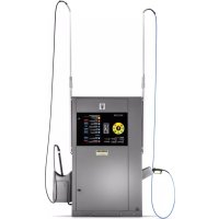
SB OB - Automatic boot washer Kärcher - Free user manual and instructions
Find the device manual for free SB OB Kärcher in PDF.


| Product type | Automatic bottle washer (self-service washing station) |
| Brand | Kärcher |
| Model | SB OB |
| Dimensions (L x W x H) | 800 x 1200 x 2100 mm |
| Weight | 330 kg |
| Power supply | 400 V / 3~ / 50 Hz, connected load from 8.7 to 30.3 kW depending on version |
| Electrical protection | Residual current circuit breaker 30 mA, IPX5 type |
| Operating pressure | 10 MPa (100 bar), max. 11 MPa |
| Water flow rate | 9.16 l/min (version 500 l/h) or 15 l/min (version 900 l/h) |
| Hot water temperature | Up to 60 °C depending on version |
| Washing programs | Power Foam, Power Wheels, High Pressure Wash, Brush + Foam, Rinse, Hot Wax, Special Insects, Intensive Wash, Top Finish |
| Number of tools | 1, 2 or 3 tools depending on version |
| Detergent tank | 4 x 10 liters |
| Hot water tank | 30 liters |
| Salt tank (optional) | 35 liters |
| Ion exchanger (optional) | Capacity BA 42 or BA 65 °dH/m³ |
| Reverse osmosis (optional) | Permeation output 60 l/h, buffer tank 65 l |
| Frost protection (optional) | Heater fan and antifreeze circuit or drain antifreeze, resistant up to -20 °C |
| Daily maintenance | Check hoses, brush, panels, sealing, detergent level |
| Weekly maintenance | Check pump oil level, clean tool holders, check operation |
| Safety | Recycling valve, motor thermal protection, winding protection contact, temperature regulator, overheat protection, dry run sensor |
| Spare parts | Use only genuine Kärcher parts |
| Warranty | According to country conditions, material or manufacturing defects |
Frequently Asked Questions - SB OB Kärcher
User questions about SB OB Kärcher
0 question about this device. Answer the ones you know or ask your own.
Ask a new question about this device
Download the instructions for your Automatic boot washer in PDF format for free! Find your manual SB OB - Kärcher and take your electronic device back in hand. On this page are published all the documents necessary for the use of your device. SB OB by Kärcher.
USER MANUAL SB OB Kärcher
Deutsch 2
English 16
Français 30
Italiano 46
Nederlands 62
Español 77
Português 94
Norsk 111
Svenska 124
Suomi 138
Русский 153
Magyar 170
Polski 185
Românește 201
Slovenčina 217
Eesti 232
Latviešu 246
Lietuviškai 262
Українська 277
Inhalt
① Deckel
② Salztank
① Touchscreen
②Elektrokasten
flowchart
graph TD
    A["Delete Fault History"] --> B{Do You Want To Delete Fault History?}
    B --> C["Yes"]
    B --> D{No}
    C --> E["4"]
    D --> F["3"]
    D --> G["2"]
    D --> H["1"]
① Düsenvorderteil
②Filter
③ Düsenhalter
natural_image
Interior view of a printer or printer unit with visible internal components and a numbered label (1), no readable text or symbols present.natural_image
3D mechanical assembly diagram showing tubing and components inside a machine (no text or symbols visible)①Deckel
H. Jenner
Chairman of the Board of Management
S. Reiser
Director Regulatory Affairs & Certification
71364 Winnenden (Germany)
Tel.: +49 7195 14-0
Fax: +49 7195 14-2212
Winnenden, 2021/06/01
Contents
General notes.... 16
Environmental protection 16
Safety instructions.... 17
Intended use 17
Initial startup.... 17
Operation 17
Controller.... 18
Frost protection (option) 22
Disconnection from system (option).... 23
Shutting down 23
Shutting down 23
Description of the unit 24
Care and service 25
Troubleshooting guide.... 27
Technical data 29
Warranty.... 30
Transport.... 30
Storage.... 30
Accessories and spare parts.... 30
Declaration of Conformity.... 30
General notes

Read these original operating instructions and the enclosed safety instructions before using the device for the first
time. Proceed accordingly.
Keep both books for future reference or for future owners.
Technical terms
Knowledge of the following terms is important for understanding the operating instructions. The technical terms in bold are used throughout these operating instructions.
Fresh water - raw water, tap water, city water
Base exchanger - WSO, water softening unit
Softened water - soft water
Reverse Osmosis (RO) - reverse osmosis
Concentrate - waste water enriched with salts and minerals from reverse osmosis
Permeate - osmosis water, demineralised water, deionised water
Processed water - water from a biological water treatment plant
Environmental protection

The packing materials can be recycled. Please dispose of packaging in accordance with the environmental regulations.

Electrical and electronic appliances contain valuable, recyclable materials and often components such as batteries, rechargeable batteries or oil,
which - if handled or disposed of incorrectly - can pose a potential threat to human health and the environment. However, these components are required for the correct operation of the appliance. Appliances marked by this symbol are not allowed to be disposed of together with the household rubbish.
Notes on the content materials (REACH)
Current information on content materials can be found at: www.kaercher.com/REACH
Supplementary environmental protection instructions
Please do not allow engine oil, heating oil, diesel and petrol to enter the environment. Please protect the ground and dispose of old oil in an environmentally friendly manner.
Safety instructions
Dangers can be presented to the operator and other persons if the device is incorrectly operated or misused:
• High water pressure
• High electrical voltage
- Detergent
To avoid danger to persons, animals and property, read the following documents before operating the system:
- These operating instructions, including all safety instructions
• The respectively applicable national regulations
- The safety instructions provided with the detergent used
Ensure the following:
• That you have understood all notes and instructions
- That all users of the system are notified of the instructions and have understood them
All persons working on the erection, installation and operation of the system must:
- Be appropriately qualified
- Know and adhere to these operating instructions
- Know and adhere to the applicable regulations
In self-service operation, ensure that clearly visible notices are present informing all users with regard to:
• Potential dangers - Safety devices
- Operating the system
△DANGER
Risk of burns from hot system components
Do not touch system components such as pumps and motors until they have cooled down.
△WARNING
Danger of injury
Do not use the system if persons without the proper protective clothing are in the vicinity.
Check the device and the accessories, such as the high-pressure hose, high-pressure gun and safety devices, to make sure they are in proper safe and reliable condition before each operation. Do not use the device if it is damaged. Replace damaged components immediately.
Only use high-pressure hoses, control panels and couplings specified by the manufacturer.
Regulations and guidelines
- Observe the respectively applicable national regulations for liquid jet cleaners.
- Observe the respectively applicable national regulations for electrical installation.
- Observe the respectively applicable national regulations for accident prevention. Have the system checked annually and store the written test results in a safe place.
- Allow only KÄRCHER Customer Service technicians or KÄRCHER-authorised technicians to perform maintenance work and repairs.
Hazard levels
⚠️DANGER
- Indication of an imminent threat of danger that will lead to severe injuries or even death.
⚠ WARNING
- Indication of a potentially dangerous situation that may lead to severe injuries or even death.
△CAUTION
- Indication of a potentially dangerous situation that may lead to minor injuries.
ATTENTION
- Indication of a potentially dangerous situation that may lead to damage to property.
Symbols on the system

⚠ WARNING
Danger from high electrical voltage. Have work on system parts with this symbol carried out by a qualified electrician only.

△DANGER
Danger of burns due to high temperature. Do not touch components marked this way.
Hearing protection
The maximum sound level of the system is 80dB(A). Hearing protection is therefore not usually required. When cleaning noise-intensifying parts, the sound level may increase. For this reason, wear suitable hearing protection in such cases.
Switching off in the event of an emergency
- Turn the programme selection switch to "STOP".
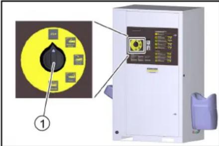
①Programme selection switch
Workstation
- Coins are inserted at the control panel and the washing programme is selected.
- Cleaning is carried out with the high-pressure gun, washing brush and power foam lance.
△DANGER
Risk of injury, risk of burns
Only operate the system with the casing closed.
- The inside of the system must only be accessible to trained personnel for maintenance work. When using the system, the door must be locked.
Intended use
This self-service washing system is used for cleaning vehicles and trailers with water and detergent additives. Cleaning humans and animals is improper use and
- is prohibited. The high-pressure water jet presents a substantial risk of injury.
- Loose objects. Loose objects can be propelled away at high speed by the high-pressure water jet and injure persons or damage other objects.
A category 5 system isolation must be installed between the system and the drinking water network to isolate the system from the drinking water network. Locally applicable regulations must also be observed.
ATTENTION
Dirty water leads to premature wear or deposits in the device.
Clean the device using only clean water, or recycling water that does not exceed the following limits:
• pH value: 6.5...9.5
• Electrical conductivity: Conductivity of fresh water + 1200 μS/cm, maximum conductivity 2000 μS/cm
- Settleable particles (sample volume 1 l, settling time 30 minutes): < 0.5 mg/l
- Filterable particles: < 50 mg/l, no abrasive substances
• Hydrocarbons: < 20 mg/l
• Chloride: < 300 mg/l
• Sulphate: < 240 mg/l
• Calcium: < 200 mg/l
- Total hardness: < 28 °dH, < 50° TH, < 500 ppm (mg CaCO₃/l)
- Iron: < 0.5 mg/l
• Manganese: < 0.05 mg/l
• Copper: < 2 mg/l
• Active chloride: < 0.3 mg/l
• Free of unpleasant odours
Systems without frost protection must be shut down when frost is expected.
When the prerequisites listed in the "Frost protection" section are satisfied, systems with frost protection can be operated at temperatures down to -20ircC and must be shut down at lower temperatures.
△DANGER
For safety reasons we recommend operating the device only via a fault current protection switch (maximum 30 mA).
Initial startup
- Switch on the on-site power supply.
- Open the on-site water stop valve.
- Unlock the locks.
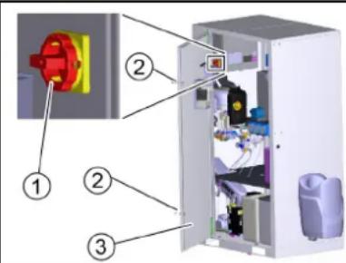
① Power switch
②Lock
③Door
- Open the door.
- Turn the trigger to 1/ON.
- Close the door.
Operation
Washing programmes
The active washing programme is selected using the washing programme switch.
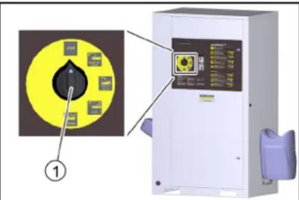
① Washing programme switch
STOP
The programme is interrupted.
Initial position. Cleaning tools in the tool mounts.
Note: The "STOP" function is active at all switch settings without a washing programme.
Power foam (only with 3-tool version)
Loosening of stubborn dirt.
Water with special detergent additive.
Minimum high-pressure jet clearance of 80 cm.
Power rim foam (optional, only with 3-tool version)
Loosening of brake residue.
Water with special detergent additive.
Exposure time max. 2 minutes. Used before the car wash and only on coated or painted wheel rims.
High-pressure wash
For removing coarse dirt.
Water with detergent.
Minimum high-pressure jet clearance of 30 cm.
Foam wash
Thorough paint cleaning with active foam.
Use the washing brush only when a program is running and after the high-pressure wash.
Rinse
Clear, cold water for rinsing off shampoo and foam.
Minimum high-pressure jet clearance of 50 cm.
Hot wax
Warm water with paint preservation.
Use only after rinsing.
Minimum high-pressure jet clearance of 80 cm.
Insects Loosening (option)
Loosening of insect residue.
Water with insect cleaner.
Minimum high-pressure jet clearance of 30 cm.
Dirt Loosening (option)
Removal of stubborn dirt.
Water with special detergent additive.
Minimum high-pressure jet clearance of 30 cm.
Top care (option)
Stain-free drying.
Demineralized water with a shine dryer.
Minimum high-pressure jet clearance of 80 cm.
Operating sequence
- Turn the program selection switch to the desired washing program.
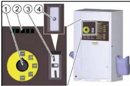
①Program selection switch
② Remaining value display (option)
③ Coin slot
④ Start button
- Insert a coin or press the start button, depending on the version of the system.
Note
While a washing program is in progress, water will escape from the nozzle of the cleaning tool even when the high-pressure gun is not actuated. Due to the frost protection function, the high-pressure gun does not close completely.
Single tool version
- To clean with the high-pressure jet, press the locking lever, pull the cleaning brush back and lock it in place.
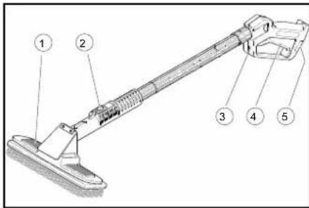
①Cleaning brush
②Locking lever
③High-pressure gun
④Trigger
⑤ Safety latch
- To clean with the cleaning brush, press the locking lever, push the cleaning brush forwards and lock it in place.
- Release the safety catch.
- Pull the trigger.
Dual tool version
This version has a high-pressure gun and cleaning brush as two separate tools.
3-tool version
There are 3 separate tools here:
• High-pressure gun
- Cleaning brush
• Power foam lance
Washing time
- The washing time starts after inserting a coin or pressing the start button.
- The remaining value display shows the remaining washing time.
Note: The washing time continues to run when the program selection switch is in the "STOP" position. If further coins are inserted during the washing time, these are registered and added to the existing washing time.
Providing the detergent
ATTENTION
Unsuitable detergents can damage the system and the object to be cleaned.
Use only detergents approved by KÄRCHER. Observe the dosage recommendations and instructions provided with the detergent. Use detergents sparingly to help conserve the environment.
△DANGER
Incorrect handling of detergents can endanger your health.
Read and observe the safety and application instructions provided with the detergent before using the detergent. Wear the protective clothing/protective equipment specified in these documents.
-
Open the device door.
-
Insert the detergent canister into the device.
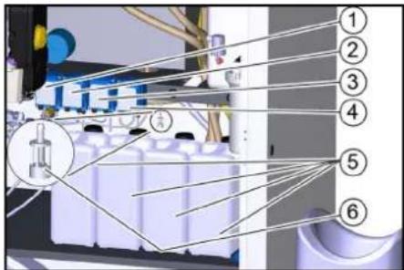
①Dosing pump 1 (yellow)
②Dosing pump 2 (red)
③ Dosing pump 3 (green, option)
④ Dosing pump 4 (Option)
⑤Detergent canister
⑥ Detergent suction filter
Note
Dosing pumps and detergent suction filters are provided with colour markings.
- Insert the detergent suction filter of the dosing pump into the detergent canister according to the assignment specified in the table below. Insert the hose far enough so that the filter lies on the bottom of the canister.
| Dosing pump | Washing program | |
| 1 (yellow) High-pressure wash RM 806 | ||
| 1 (yellow) Foam wash RM 806 | ||
| 2 (red) Hot wax RM 820 | ||
| 3* (green) Insects Loosening RM 806 | ||
| 3* (green) Dirt Loosening RM 806 | ||
| 4* (green) Power foam RM 838 | ||
| 4* (white) | Power rim foam | RM 802 |
| 4* (red) | Top care | RM 821 |
* Option
Vent the dosing pump
- Use the programme selection switch to select a programme that uses the relevant detergent.
- Run the washing programme until the suction hose is bubble-free.
Replenishing softening salt (only with base exchanger option)
ATTENTION
Malfunctions possible
Unsuitable salt can impair the function of the base exchanger.
Only use the softening salt in tablet form given in the "Accessories" chapter.
- Remove the salt tank cover.
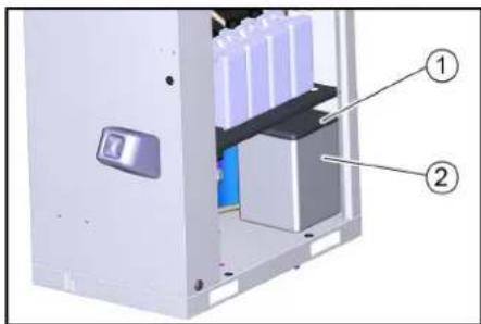
① Cover
② Salt tank
-
Fill the salt tank to the very top with softening salt.
-
Fit the salt tank cover.
Note
An empty salt tank will cause a malfunction. Fill the salt tank at the latest when water is visible in the salt tank after removing the cover.
The salt consumption does not increase when the salt tank is completely full.
In a correctly working system, the salt consumption is constant in relation to the water consumption.
We recommend documenting the salt and water consumption in an operating log,
Settings at base exchanger BA 42 and BA 65
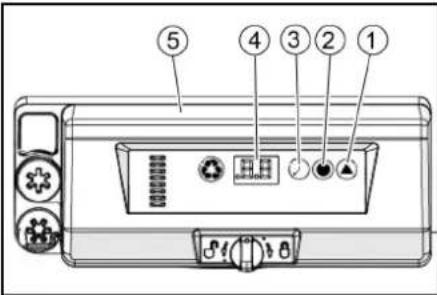
① Hardness button
② Salt button
③ Time button
④ Display
⑤ Base exchanger control head
Setting the regeneration cycle
- Press the hardness button on the control head of the base exchanger repeatedly until the desired interval is shown in the display.
| 0 | Deactivated |
| 0.3 | Regeneration every 8 hours |
| 0.5 | Regeneration every 12 hours |
| 1...30 | Regeneration every X days |
Note
The factory setting is 0/Deactivated. The setting must be adjusted to the local conditions by the service technician when the device is installed.
Setting brine dosage
Note
The display shows the dosing amount in kg during the setting.
- Press the salt button repeatedly until the desired brine dosage is shown on the display.
Target setting:
BA 42: 2.5 kg
BA 65: 4.5 kg
Setting the time
Note
When setting, the current hour is selected. The minutes are reset to zero at the time of entry.
1. Press the time button repeatedly until the current hour is shown on the display.
Controller
The touchscreen is mounted on the electrical box inside the system.
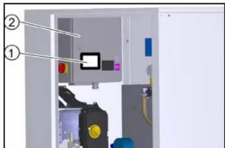
① Touchscreen
② Electrical box
The following functions are displayed in the start menu.
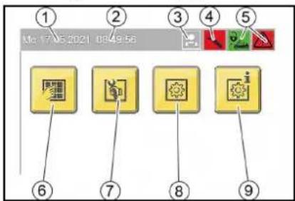
Start menu
①Date
②Time
③ Logged on user
④Service required
⑤ Operating state symbols
⑥ "Washing" menu button
⑦"Service" menu button (only accessible to service staff with password)
⑧"Settings" menu button
⑨"General Info" menu button
Operating state symbols

System open

System closed

System OK

Event present

Malfunctions present
User symbols

Operator

Owner

Service
Changing the setting
- Press the Change Setting button next to the property you want to change.

Change Setting button
A selection window opens to select the desired setting or a keyboard opens to enter the desired value.
Menu overview
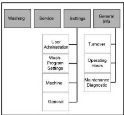
flowchart
graph TD
    A["Washing"] --> B["Service"]
    B --> C["Settings"]
    C --> D["General Info"]
    C --> E["User Administration"]
    C --> F["Wash-Program Settings"]
    C --> G["Machine"]
    C --> H["General"]
    E --> I["Turnover"]
    F --> J["Operating Hours"]
    G --> K["Maintenance Diagnostic"]
Menu Washing
The current operating state of the system is displayed in the Washing menu.
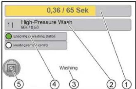
①Credit (amount) / remaining washing time
② Running washing programme
Run time per wash value / (cash) amount corresponding to one wash value
③Name of the menu item
④Display: System open (green) or system closed (red)
⑤Home button
press briefly - go back one menu level
press long - go back to start menu
Menu Service
The Service menu is only accessible for customer service.
Menu Settings
The operating parameters of the system are set in the Settings menu.
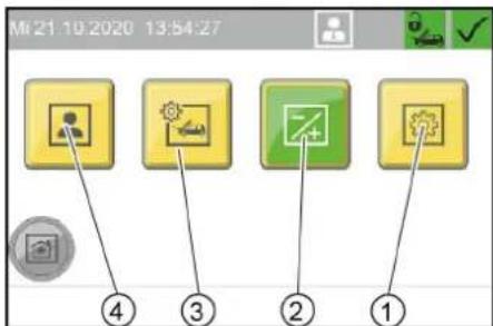
①"General" menu button
②"Machine" menu button
③"Wash-Program Settings" menu button
④"User Administration" menu button
Menu User Administration
The user group is selected in the User Administration menu. Different user groups have different access permissions

①"Service" button
②"Owner" button
③"Operator" button
A code must be entered when selecting the user groups "Owner" and "Service".
Note
Default code Owner: 1234
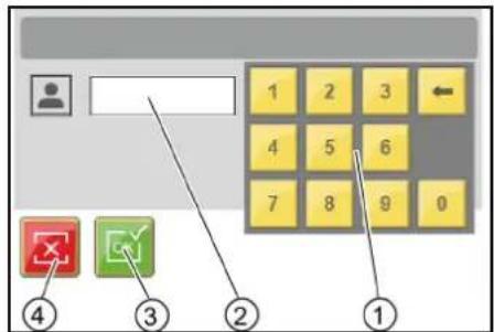
① Keyboard
② Input field
③ Confirm the entry
④ Delete the entry
Changing code
For the user group Owner, the code can be changed after logging in.
- Press the "..." button.
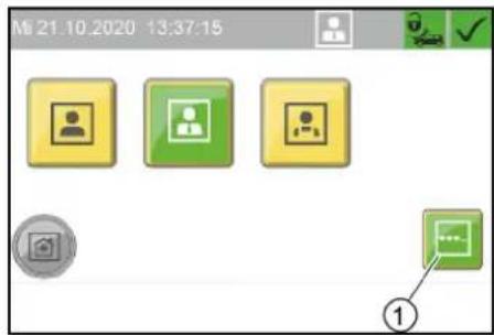
①"..." menu button
2. Enter the desired code in the "EnterNew Code" window.
3. Enter the same code again for confirmation in the "Confirm New Code" window.
Menu Wash-Program Settings
The parameters of the individual washing programs are adjusted in the Wash-Program Settings menu.
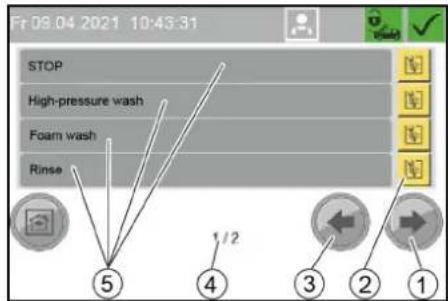
① Next window button
② Change washing program button
③ Previous window button
④ Window 1 of 2
⑤ Washing program designation
Changing the parameters of a washing program
- Select the window with the desired washing program. Use the Next Window and Previous Window buttons for this.
- Press the Change washing program button next to the desired wash program.
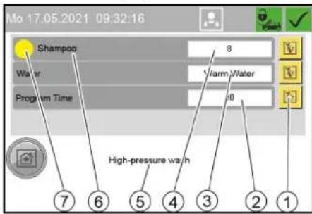
① Change parameters button
② Program running time for one wash value in seconds
③ Water type (hot water/cold water)
④ Detergent dosing (in % of the dosing pump capacity)
⑤ Washing program name
⑥ Detergent designation
⑦ Change detergent button (the colour corresponds to the colour code on the dosing pump)
- Press the button to change the desired parameter.
- Press the desired parameter in the displayed selection. Standard setting
| Washing pro-gram | Dosing pump | water type | Program duration |
| High-pressure wash | 1 (yellow) W | warm 90 s | |
| Foam wash 1 (yellow) 135 s | |||
| Rinse - Cold 105 s | |||
| Hot wax 2 (red) | Warm 54 s | ||
| Insects Loosening | 3 (green) | Wam | 75 s |
| Dirt Loosening | 3 (green) | Warm 75 s | |
| Power foam | 60 s | ||
| Power rim foam | 60 s | ||
| Top care | Cold 75 s | ||
| Washing pro-gram | Detergent dosing | |||
| 500 l/h | 900 l/h | |||
| % | ml/min % | % | ml/min | |
| High-pressure wash | 8 | Approx. 6 | 16 | Approx. 12 |
| Foam wash | 8 | Approx. 6 | 16 | Approx. 12 |
| Rinse | - | - | - | - |
| Hot wax | 10 | Approx. 7 | 20 | Approx. 14 |
| Insects Loosening | 20 | Approx. 14 | 40 | about 28 |
| Dirt Loosening | 20 | Approx. 14 | 40 | Approx. 28 |
| Power foam | 30 | Approx. 21 | 30 | Approx. 21 |
| Power rim foam | 30 | Approx. 21 | 30 | Approx. 21 |
| Top care | 10 | about 7 | 20 | Approx. 14 |
Menu Machine
In the Machine menu, system parameters are set and the washing station can be locked.
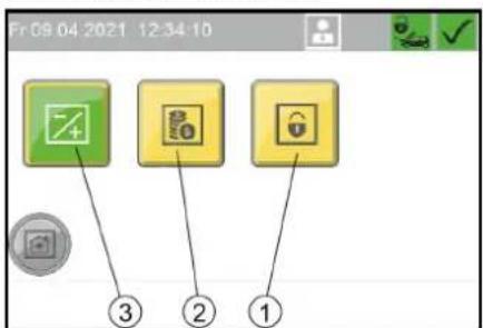
①"Lock" menu button
②"Coin value" menu button
③"Components" menu button
Menu Components
In the Components menu, the temperature of the hot water can be set.
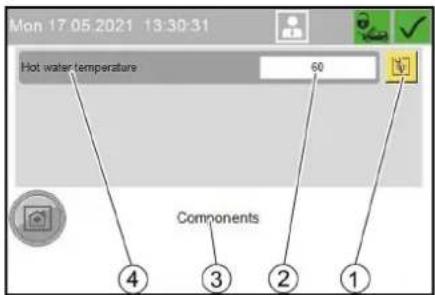
①Change numerical value button
②Hot water temperature in °C
③Menu Components
④ Hot water temperature
Menu Coin value
In the Coin value menu the wash value for 100% program run time and the coin values for the individual channels of the coin acceptor are set.
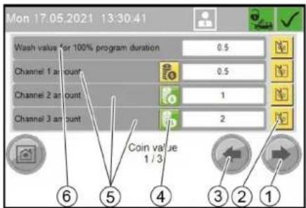
①Next window button
②Change setting button
③Previous window button
④Balance button
green: Coins of this channel are included in the turnover
Yellow: Coins are not included in the balance sheet
⑤Coin values:
- Channel ... amount: Channels of an electronic coin acceptor
- External amount: Mechanical coin acceptor
- External 1 amount: Payment system with RFID
⑥Required coin value for 100% run time of a washing program
-
Press the Setting button next to the desired value.
-
Enter the desired value.
Menu Lock
In the Lock menu, the washing station is locked or unlocked. The lock is effective regardless of the set opening hours.
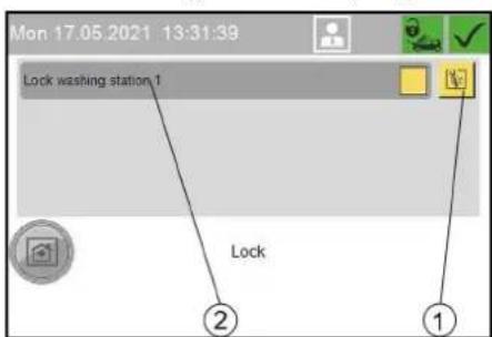
① Change Setting button
②Locking washing station 1
1. Press the Change Setting button.
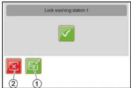
①Lock Washing Station button
②Unlock button
- Press the desired button.
Menu General
In the General menu, the time, date and operating times are set and the display language is selected.
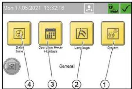
① "System" menu button Only for service staff
②"Language" menu button
③"Operation Hours Holidays" menu button
④"Date Time" menu button
Menu Date Time
The time, date and summer time are set in the Date Time menu.

① Set Date button
② Set Time button
③ Summer time active display
④ Set date
⑤ Set time
⑥ Summer time/standard time changeover button
Setting the time
- Press the Set Time button.
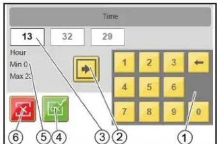
① Keyboard
② Change input field button
③ Active input field
④ Apply button settings and exit window
⑤ Name of active field, minimum value, maximum value
⑥ Exit window button, do not accept changes
-
Use the Change Input Field button to select the desired input field.
-
Delete the field content with the delete key on the keyboard.
-
Enter the desired value with the keyboard.
-
Repeat the process until all desired changes have been made.
-
Exit the window.
Note
The date is set according to the same principle as described for the time.
Menu Operation Hours Holidays
In the Operation Hours Holidays menu, the opening hours are defined for each weekday and for public holidays. Fixed and changing public holidays are also defined.
The setting is made according to the same principle as in the Date Timemenu.
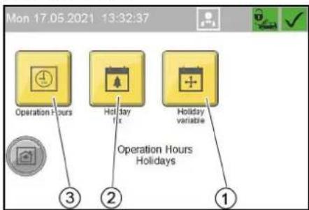
①"Holiday variable" menu button
②"Holiday fix" menu button
③"Operation Hours" menu button
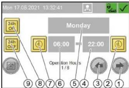
Menu Operation Hours
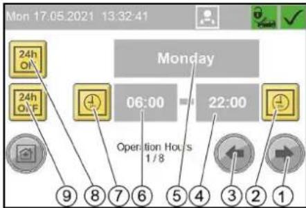
①One weekday forwards button
② Set end of operation button
③One weekday back button
④ Time of end of operation
⑤Weekday (Monday...Sunday, public holiday)
⑥ Time of start of operation
⑦ Set start of operation button
⑧ Open all day button
⑨ Closed all day button
Menu Holiday fix
Fixed public holidays always occur on the same date each year.
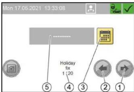
① Next public holiday button
②Previous public holiday button
③ Set Date button ④ 1st public holiday of 20 public holidays ⑤ Date of the public holiday (in the example no date is set yet)
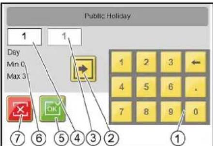
①Keyboard
② Change input field button
③Month
④Day (currently active input field)
⑤Apply button settings and exit window
⑥Name of active field, minimum value, maximum value
⑦ Exit window button, do not accept changes
Menu Holiday variable
Changing public holidays occur at a different date each year.
The setting is made in the same way as for Holiday fix, except that here the year must also be set.
Menu Language
This menu is used to select the language in which the display is shown.
Menu General Info
In the General Info menu, turnover, operating hours, maintenance information and fault messages can be viewed.
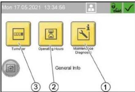
①"Maintenance Diagnostic" menu button
②"Operating Hours" menu button
③"Turnover" menu button
Menu Turnover
In the Turnover menu, the total turnover and daily turnover are displayed.
The daily turnover can be deleted.
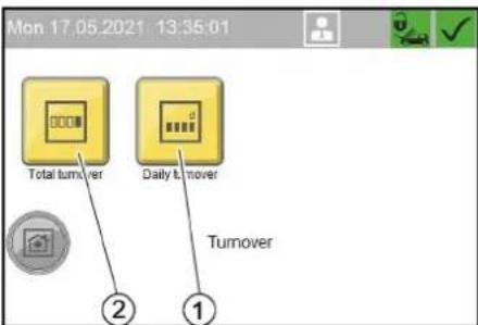
①"Daily turnover" menu button
②"Total turnover" menu button
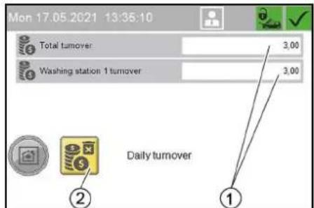
Daily turnover
①Daily turnover of system = daily turnover at washing station 1
② Delete turnover button (only for daily turnover)
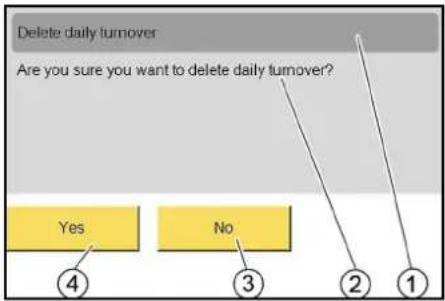
① Delete daily turnover
②Are you sure you want to delete daily turnover?
③No
④Yes
Menu Operating Hours
In the Operating Hours menu, the operating hours of individual system components and the individual washing programmes are displayed.
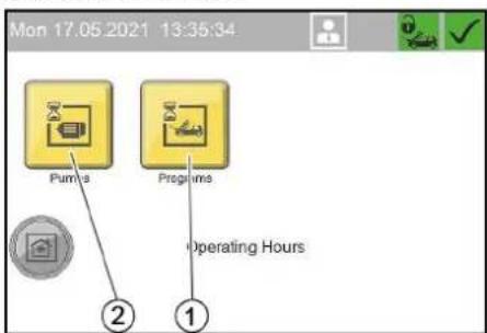
①"Programs" menu button, operating hours of washing programmes
② "Pumps" menu button, operating hours of system components
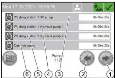
Operating hours of system components
① Next window button
②Previous window button
③ Operating hours of high-pressure pump
④ Operating hours of dosing pump 1
⑤ Operating hours of dosing pump 2
⑥ Operating hours of RO pump (option)
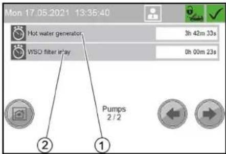
① Operating hours of hot-water generator ② Operating hours of ultra-fine filter (WSO
Note
The menu with the operating hours of the washing programmes is structured according to the same principle.
Menu Maintenance Diagnostic
The Maintenance Diagnostic menu shows the times until the next maintenance, system information, error messages and events.
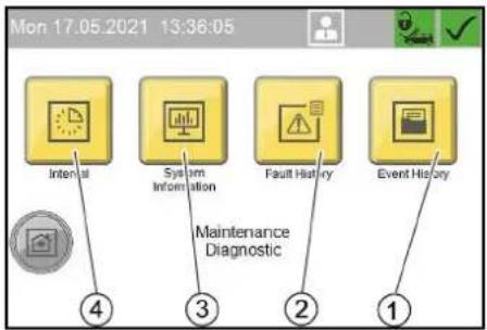
①"Event History" menu button
②"Fault History" menu button
③ "System Information" menu button
④"Interval" menu button
Menu Interval
In the Interval menu, the time until the next maintenance is displayed for the individual system components.
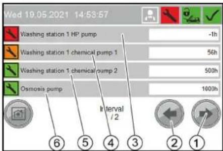
① Next window button
②Previous window button
③Remaining run time of high-pressure pump
④ Remaining run time of dosing pump 1
⑤ Remaining run time of dosing pump 2
⑥ Remaining run time of RO pump (option)
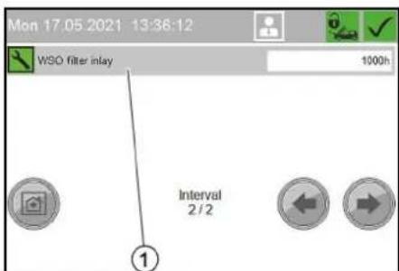
① Remaining run time of ultra-fine filter (WSO)
Menu System Information
In the System Information menu, system data, settings of the control and operations data of the control are displayed.
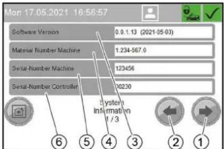
①Next window button
②Previous window button
③ Software version
④ Material number of the system
⑤ Serial number of the system
⑥ Serial number of the control
![Mon 17.05.2021 16:57:35 IP-Settings Controller 192 / 255 Run-Time Controller [h]: 235 Date Of Commissioning —— Last Maintenance —— System Information 2 / 3 ④ ③ ② ①](/content/2026/03/557405/images/c2a43f2f23e1926d8e4be16400a39b71aa097cd6fe742dd7aab0f32b2136ac11.jpg)
①IP settings of the control
②Run time of the control in hours
③ Initial startup date
④Last service
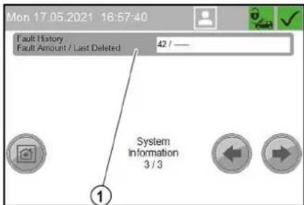
①Current number of faults in the fault memory / last reset of the fault memory
Menu Fault History
In the Fault History menu, the error messages since the last deletion of the fault memory are displayed.
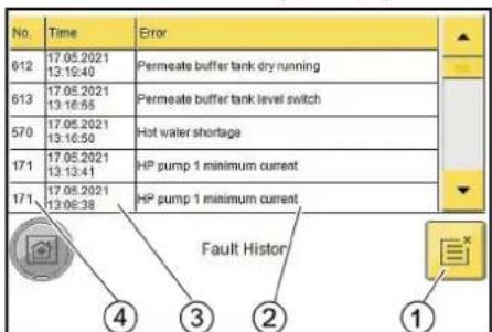
①Delete fault memory button
② Error description
③Time of the error message
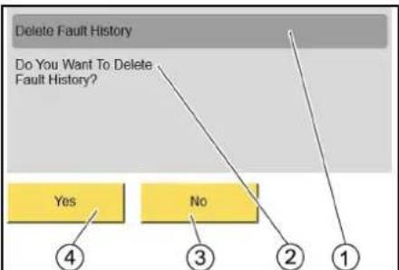
④ Error number
flowchart
graph TD
    A["Delete Fault History"] --> B{Do You Want To Delete Fault History?}
    B --> C["Yes"]
    B --> D{No}
    C --> E["4"]
    D --> F["3"]
    D --> G["2"]
    D --> H["1"]
① Delete the fault memory
②Are you sure you want to delete the fault memory?
③ No
④ Yes
Menu Event History
The Event History menu is structured in the same way as the Fault History menu.
Frost protection (option)
The frost protection device consists of a hot air blower and antifreezing circulation or frost protection with lost water. Note: The presence of a frost protection system ensures the following properties:
- Restricted washing operation at temperatures below -5ircC . In restricted washing operation the washing brush must be regularly checked for icing. Brush washing with an iced washing brush can damage the vehicle. If the washing brush is iced up, the washing brush must be disabled or, in the case of the 1-tool version, the combination spray lance must be replaced with a high-pressure spray lance. Please contact your Customer Service responsible if washing operation is to be extended to lower temperatures. At temperatures below -15ircC , washing makes no sense because an ice coating forms on the vehicle. This ice coating can even impair the function of important vehicle components. For this reason, you must lock the system at temperatures less than -15ircC .
- Frost protection of the system down to -20ircC . At temperatures less than -20ircC the "Frost shutdown" procedure is to be performed.
△WARNING
Frost protection water running onto the washing station can lead to the formation of black ice under frosty conditions.
Insert the high-pressure gun into the brush chute after use. ⚠ WARNING
Black ice on the washing station presents an increased danger of accidents.
Lock the washing station if there is a danger of black ice.
Prerequisites for frost protection
- An uninterruptible power supply and water supply must be ensured. The water supply must be protected against frost.
- Technically correct erection and installation of the system.
• The hot air blower is set correctly. - All maintenance measures described in the "Maintenance and care" chapter have been performed.
- All cleaning tools are placed back in the tool holders.
- The high-pressure gun with frost protection bore belonging to the system is installed.
- The hose line from the system to the cleaning tool has not been extended or replaced with a longer hose.
- The temperatures stated above relate to the installation site. Temperatures stated in weather forecasts are secondary.
Hot air blower
The hot air blower heats the interior of the system to provide frost protection.
- Turn the performance controller to level "I".
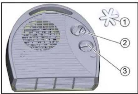
① Frost protection symbol
②Thermostat control
③ Power controller
- Adjust the thermostat controller according to the exterior temperature:
a If the exterior temperature is higher than -10 °C, set the thermostat controller to the frost protection position.
b If the exterior temperature is lower than -10 °C, set the thermostat controller to level "I".
Note: The frost protection device only works when the system is switched on and the door is closed. The trigger must therefore not be set to "0/OFF". The system power supply must not be interrupted either. Operation of the hot air blower is interrupted during operation of a high-pressure pump.
△DANGER
The hot air blower can overheat and cause a fire if the air inlets and air outlets are covered.
Never cover the air inlets and air outlets of the hot air blower.
ATTENTION
The frost protection cannot be maintained in the event of a power failure.
Perform a frost protection shutdown in the case of a power failure.
Anti-freezing circulation circuit
If there is a risk of frost, circulating water flows through the cleaning tools and their supply lines, thus protecting them from freezing.
The anti-freezing circulation circuit is placed in operation by the anti-freezing pump.
The following components show that the system is equipped with an antifreezing circulation:
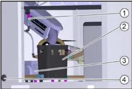
①Frost protection ball tap with sieve
②Frost protection float tank
③Frost prot. pump
④Frost protection pump filter
Frost protection with lost water
If there is a risk of frost, fresh water flows through the cleaning tools and their supply lines, thus protecting them from freezing. The water is then discharged into the waste water system.
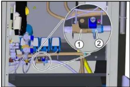
The presence of the frost protection solenoid valve indicates that the system is equipped with this frost protection version.
natural_image
Interior view of a medical or laboratory facility with numbered annotations (1 and 2) showing internal components and equipment (no readable text or symbols)① Frost protection solenoid valve
②Frost protection ball tap
Maintenance work before and after the frost period
For a better overview, the maintenance work required to ensure correct operation of the frost protection system is summarised again here. To check the frost protection
system, the work must also be performed annually before the frost period begins. The maintenance work de-
scribed in the "Maintenance and care" chapter must also be performed in winter.
| Time & date | Activity | Performed | By whom |
| Before the frost period | Clean the frost protection pump filter. | Clean the filter and re-insert. | Operator |
| Cleaning the filter in the Power foam nozzle (option) | Remove and clean the filter (see "Cleaning the Power foam nozzle filter"). Determine the following cleaning intervals according to experience. | Operator | |
| Several times a day under frosty conditions | Check the washing brush | Check for dirt and ice and lock the brush cleaning if necessary. | Operator |
| Daily under frosty conditions | Check the interior spaces of the system. | Is the hot air fan operating?Is the setting of the thermostat regulator correct (warmer than -10 °C - level "I", colder than -10 °C - level "II")? | Operator |
| Daily during frost, only with frost protection circuit | Check the tool holders. | Is the frost protection float tank outlet free? | Operator |
| Clean the sieve. | See the section "Care and maintenance/Cleaning the sieve". | Operator | |
| Clean the frost protection pump filter. Clean the filter and re-insert. Operator | |||
| After 160 operating hours or monthly | Check the antifreeze water quantity | Minimum value: approx. 0.5 l/min per washing tool (the tool with the lowest flow is decisive).Water quantity smaller with frost protection circuit: Clean the frost protection pump filter, clean the sieve (on the frost protection ball tap), flush the line.Larger water quantity for all tools: Regulate the water quantity with the frost protection ball tap.Larger water quantity only at the high-pressure gun: Replace the node piece in the high-pressure gun.⚠ WARNINGThe high-pressure gun can move uncontrollably and cause injuries if the frost protection water quantity is too high.Be sure to replace the node piece in the high-pressure gun if the frost protection water quantity is too high. | Operator |
Power foamClean the nozzle
- Unscrew the front part of the nozzle.
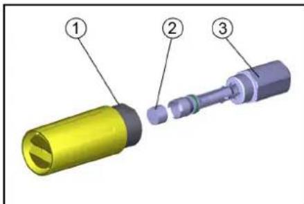
① Nozzle front part
②Filter
③ Nozzle holder
2. Remove and clean the filter.
3. Install the filter.
4. Screw the front part of the nozzle on to the nozzle holder and tighten it.
Disconnection from system (option)
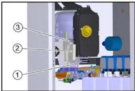
For disconnection from the water supply, the system is supplied with water from a float tank with downstream booster pump.
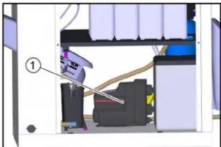
natural_image
Interior view of a printer or printer assembly with visible internal components and a numbered label (1), no readable text or symbols present.①Pressure booster pump
Shutting down
- Turn the power switch to "0/OFF".
Shutdown in the case of potential frost
Shut down a system without frost protection (see "Shutting down" chapter).
For a system with frost protection:
1. Leave the trigger at position "1".
2. Lock the washing station in the "Washing" menu item of the control.
Shutting down
If there is no danger of frost during the shutdown period:
- Close off the water supply.
- Switch off the power supply.
Shutdown in the case of potential frost
Perform the following additional steps in the case of potential frost:
- Empty all float containers.
- Unscrew the hoses at the float containers and allow them to drain completely.
- Unscrew the hoses from the high-pressure pump and allow the water to drain.
- Unscrew the high-pressure hose from the pump head and allow the water to drain.
- Remove the detergent canister and store it in a frost-protected place.
In case of doubt, have the maintenance performed by Customer Service.
Additionally for the WSO attachment kit
- Remove the RO membranes and store them in a frost-protected place.
- Empty the permeate buffer tank.
- Flush the system (without base exchanger) with antifreeze solution.
- Rinse the base exchanger with concentrated salt solution.
- Blow out all parts containing water with oil-free compressed air.
Note
During longer breaks in operation, the system, with the exception of the base exchanger, must be flushed with antifreeze solution to protect it from corrosion. In case of doubt, have the shutdown performed by Customer Service.
Description of the unit
Flow chart
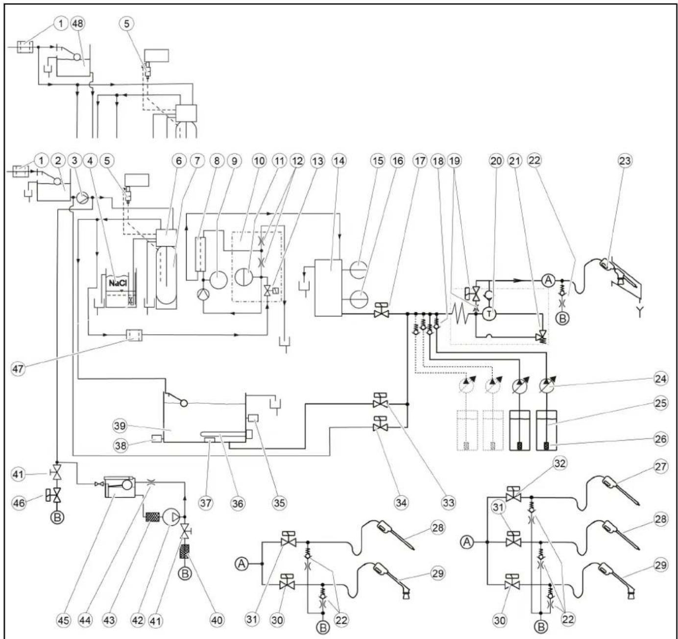
flowchart
graph TD
    A["1 48"] --> B["5"]
    B --> C["1 2 3 4 5"]
    C --> D["NaCl"]
    D --> E["6 7 8 9 10 11 12 13 14"]
    E --> F["15 16 17 18 19"]
    F --> G["20 21 22"]
    G --> H["23"]
    H --> I["T"]
    I --> J["A"]
    J --> K["B"]
    K --> L["Y"]
    M["47"] --> N["39"]
    N --> O["38"]
    O --> P["37"]
    P --> Q["36"]
    Q --> R["35"]
    R --> S["34"]
    S --> T["33"]
    T --> U["24"]
    U --> V["25"]
    V --> W["26"]
    W --> X["27"]
    X --> Y["32"]
    Y --> Z["A"]
    Z --> AA["31"]
    AA --> AB["28"]
    AB --> AC["29"]
    AC --> AD["30"]
    AD --> AE["22"]
    AE --> AF["B"]
    AF --> AG["28"]
    AG --> AH["A"]
    AH --> AI["31"]
    AI --> AJ["28"]
    AJ --> AK["29"]
① Fresh water fine filter, on-site
② Cold water float tank with mains isolation cat. 5 9
③ Advance pressure pump 9
④ Salt tank 1
⑤ Hardness sensor 1
⑥ Base exchanger control head 1
⑦ Base exchanger bottle 1
⑧RO membrane 2
⑨Pressure gauge 2
⑩Distributor block 2
⑪Pressure sensor 2
⑫Choke 2
13 Soft water solenoid valve 2
⑭Permeate buffer tank 2
15 BUFFER TANK FULL level switch 2
⑯ BUFFER TANK EMPTY level switch 2
⑰Permeate solenoid valve 2
⑱ Detergent check valve
⑲Half load bypass valve with choke 3
⑳High-pressure pump
②1Pressure relief valve
②Frost protection check valve and choke 4
②3Trigger gun with washing brush (1-tool version)
⑳Dosing pump
⑲Detergent suction hose
②6Detergent suction filter with foot valve
27 Power foam lance (3-tool version)
⑳High-pressure gun with spray lance 5
29 Foam lance 5
③0 Foam solenoid valve 5
③1High pressure (solenoid valve option) 5
③2 Power foam lance solenoid valve 6
③3Hot water solenoid valve
③4 Cold water solenoid valve
③5Hot water temperature sensor
③6 Electrical heating element
③7 Temperature limiter
38Dry running sensor
⑲Hot water float tank
④0 Sieve 7
④1 Frost protection ball tap 7
④2 Frost protection pump 7
④3 Frost protection pump filter 7
④4 Choke 7
④5 Frost protection float tank 7
④6 Frost protection solenoid valve 8
④7 Ultra-fine filter 2
④8 Cold water float tank without mains isolation 10
1 Only for water softening option
2 Only for reverse osmosis option
3 Only for high-pressure pump type 908
4 Only for frost protection option (all variants)
5 Only for 2-tool and 3-tool version
6 Only for 3-tool version
Only for frost protection circuit
8 Only for frost protection with waste water
9 Only for variants with mains isolation cat. 5
10 Only for variants without mains isolation
Monitoring and safety devices
Pressure relief valve
If the lever of the high-pressure gun is released, the circulation valve opens but the high-pressure pump remains in operation. The high-pressure jet is immediately available when the trigger gun is opened again.
Motor circuit breaker
The motor circuit breaker shuts off the device if power consumption is too high.
Winding protection contact
A winding protection contact is only installed in models with 900 l/h.
The winding protection contact in the motor winding of the pump drive sends a signal to the controller in the case of thermal overload. This switches the motor off.
Temperature controller
The temperature sensor switches the electrical heating element on when the water temperature in the hot water float tank falls and switches it off again when the maximum temperature is reached.
Overheating protection
The float switch in the hot water float tank switches the electrical heating element off if the water level is too low.
Dry running sensor
Prevents operation of the electric heating element when the hot water float tank is empty.
Hard water sensor
Only for systems with base exchanger.
If the residual hardness of the softened water exceeds a limit value, the control calculates the residual capacity of the base exchanger bottle.
Regeneration of the base exchanger bottle is started the following night at the latest.
Pressure sensor
Only for systems with reverse osmosis.
If there is water shortage, the system is stopped to prevent the RO pump from running dry.
Buffer tank full level switch
Only for systems with reverse osmosis.
Switches off the RO pump when the permeate buffer tank is full.
Buffer tank full level switch
Only for systems with reverse osmosis.
Switches on the RO pump when the permeate buffer tank is full.
Care and service
Maintenance instructions
Regular maintenance according to the following maintenance plan is fundamental for a safely operating system.
Use only original manufacturer spare parts or parts recommended by the original manufacturer, such as
- Spare parts and wearing parts,
- Accessories
- Operating materials,
- Detergent.
△DANGER
Danger of death from electric shock.
Switch off the device at the on-site main trigger and secure against being switched on again before working on the device.
Allow only qualified electricians to work on electrical components of the system.
△WARNING
A high pressure water jet can escape from damaged parts and cause injuries.
Depressurise the system by turning the trigger to "0/OFF" and then opening the high-pressure gun until the pressure has been released from the system.
ATTENTION
A high-pressure water jet can damage system components.
Do not clean the interior of the system with the high-pressure jet. When performing exterior cleaning, keep the high-pressure jet away from the upper section of the system (with coin slot, remaining value display and program switch).
-
Switch off the on-site main switch and secure it against being switched on again.
-
Disconnect the water supply.
Who is permitted for perform maintenance work?
Operator: Work labelled with "Operator" may only be performed by instructed persons capable of operating and maintaining high-pressure systems.
Customer Service: Work labelled with "Customer service" may only be performed by KÄRCHER customer service technicians or KÄRCHER-authorised technicians.
Safety inspection/maintenance contract
You can agree on regular safety inspections or close a maintenance contract with your dealer. Please seek advice on this.
System overview
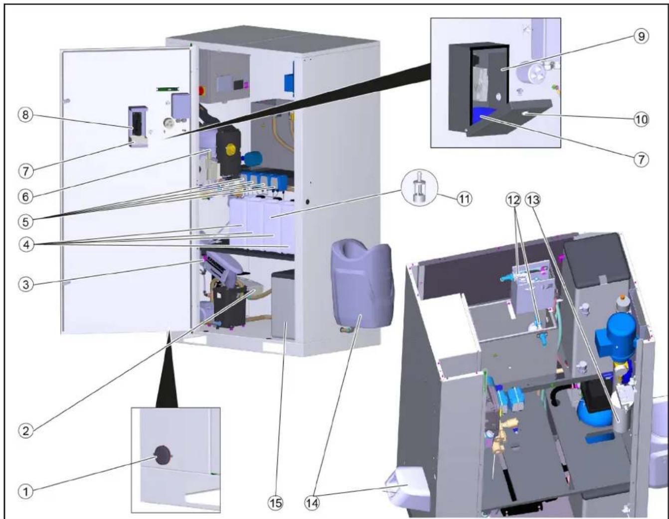
①Frost protection pump filter
② Hot air blower
③ Frost protection ball tap with sieve
④ Detergent canister
⑤ Dosing pump
⑥High-pressure pump
⑦Coin box
⑧Coin acceptor, coin slot
⑨ Lockable coin cassette (option)
⑩Lock
⑪ Detergent filter
⑫Float valve
⑬ WSO ultra-fine filter
⑭ Tool holder
⑮ Salt tank
WSO: Only carry out on systems with base exchanger
RO: Only carry out on systems with reverse osmosis.
| Time & date | Activity | Performed | By whom |
| Daily | Check the high-pressure hoses. | Examine the high-pressure hoses for mechanical damage such as abrasion damage, visible hose fabric, kinks and cracked rubber. Replace damage high-pressure hoses. | Operator |
| Check the washing brush. | Check the washing brushes for damage, soiling and wear. Replace bristles that are shorter than 30 mm. In winter at temperatures below -5 °C, check for ice formation and lock the foam wash if necessary. Replace the combination spray lance with a high-pressure spray lance for this | Operator | |
| Check the information notices at the washing station. | Check that the user information notices are present and legible. Operator | ||
| Check the leak-tightness of the system. | Check pump and line system for leaks. Contact Customer Service when oil is present under the high-pressure pump or when more than 3 drops of water per minute escape from the high-pressure pump during operation. | Operator | |
| Check the detergent filling level. Check the | filling level and refill if necessary. Operator | ||
| Emptying the coin box Open the appliance | door and empty the coin box. | ||
| For systems with frost protection: Daily in the case of frost | Check the frost protection devices. Is the | hot air fan operating?Is the setting of the thermostat regulator correct (warmer than -10 °C - level "I", colder than -10 °C - level "II")?Is the frost protection device operating (frost protection water quantity of approx. 0.5 l/min)?Is the tool holder drain opening free? | Operator |
| Clean the sieve. | See the section "Cleaning the sieve". | Operator | |
| Clean the frost protection pump filter. | Clean the filter and re-insert. | Operator | |
| After 40 operating hours or weekly | Check the oil level of the high-pressure pump. | The oil level must lie between the MIN and MAX marks, otherwise refill with oil. | Operator |
| Check the oil level. | Milky oil indicates water in the oil. Notify Customer Service. | Operator | |
| Clean the tool holders. | Remove dirt from the tool holders. | Operator | |
| Checking detergent filter | Visually check the high-pressure jet for the presence of detergent, clean detergent filter if necessary. | Operator | |
| Check for correction function | Checking the functionality of all washing programs | Operator | |
| WSO: Checking the salt tank | Is the salt level above the water level? Top up the softening salt if necessary. | Operator | |
| WSO: Check the residual hardness of the softened water | Remove water from the hot water float tank and determine the residual hardness with test set B (order no. 6.768-003). Target value: Less than 3 °dH. | Operator | |
| Cleaning the outside of the housing | Mix a 10% solution of the "Washing hall and tile cleaner RM 841" detergent, apply to the surfaces, allow to react for approx. 2 to 3 minutes, do not allow to dry. After the contact time, rinse thoroughly with the high-pressure jet. | Operator | |
| Mix a 20% solution of "Washing Hall and Tile Cleaner RM 841" detergent, apply to the surface and allow to react for approx. 2 to 3 minutes. After the contact time, clean the surfaces with a damp pad or microfibre cloth and then rinse thoroughly with a high-pressure jet. If desired, the large surfaces can be wiped off with a rubber squeegee. | Operator | ||
| Cleaning the splash guard tarpaulins | Mix a 10% solution of the "Washing hall and tile cleaner RM 841" detergent, apply to the surfaces, allow to react for approx. 2 to 3 minutes, do not allow to dry. After the contact time, rinse thoroughly with the high-pressure jet.ATTENTIONRisk of damageSolvents and detergents containing solvents can damage the splash guard tarpaulins.Do not clean the splash guard tarpaulins with solvents or detergents containing solvents. | Operator | |
| Once, 1 month after initial startup | WSO: Changing the WSO ultra-fine filter | Shut off the fresh water inlet, unscrew the filter cup, replace the filter insert, refit the new filter insert and filter cup, open the fresh water inlet. | Operator |
| After 80 operating hours or fortnightly | Clean and care for the housing. | Thoroughly clean the exterior and interior of the housing. | Operator |
| After 160 operating hours or monthly | Checking the frost protection water quantity. | Minimum value: approx. 0.5 l/min per washing tool (the tool with the lowest flow is decisive).Water quantity smaller with frost protection circuit: Clean the frost protection pump filter, clean the sieve (on the frost protection ball tap), flush the line.Larger water quantity for all tools: Regulate the water quantity with the frost protection ball tap.Larger water quantity only at the high-pressure gun: Replace the node piece in the high-pressure gun.△WARNINGThe high-pressure gun can move uncontrollably and cause injuries if the frost protection water quantity is too high.Be sure to replace the node piece in the high-pressure gun if the frost protection water quantity is too high. | Operator |
| Clean the detergent filters in the detergent containers. | Remove the filter and rinse thoroughly with clean water. | Operator | |
| WSO: Checking the salt tank | Check the water level (approx. 5...25 cm above the sieve plate). | Operator | |
| Check for deposits, empty if necessary, clean, refill with softening salt and put back into operation. Danger of malfunctions. When topping up with softening salt, use only the softening salt in tablet form listed in the chapter 'Accessories'. | Operator | ||
| Lubricate the door hinges. | Lubricate the hinges with grease (order no.: 6.288-072). | Operator | |
| Lubricate the locks for doors and control cabinet doors. | Spray care agent (order no.: 6.288-116) into the locks. | Operator | |
| Quarter-yearly | Cleaning the coin slot | Open the device door. Clean the coin slot (see section "Maintenance work"). | Operator |
| After 250 operating hours or half-yearly | Check the pump head. | Customer Service | |
| Check the fresh water float valves. | If water escapes from the overflow hose, check the seal at the float valve. If necessary, replace the float valve. | Operator/Customer Service | |
| Check the pump hose in the dosing pump. | Check the pump hose for cracks and wear and replace if necessary. | Operator/Customer Service | |
| After 500 operating hours or annually | Completely check the high-pressure pumps. | Customer Service | |
| Replace the oil in the high-pressure pump. | See Maintenance work. | Operator | |
| Annually before the frost period | Cleaning the filter in the Power foam nozzle (option) | See "Cleaning the frost protection/Power foam nozzle". Determine the following cleaning intervals according to experience. | Operator |
| Every 1000 operating hours | WSO: Changing the WSO ultra-fine filter | Shut off the fresh water inlet, unscrew the filter cup, replace the filter insert, refit the new filter insert and filter cup, open the fresh water inlet. | Operator |
| Safety check | Safety check according to the directives for liquid jet cleaners/accident prevention guideline. | Customer Service |
Oil change
△WARNING
Danger of burns
The high-pressure pump and the engine oil are hot and cause burns if touched.
Allow the high-pressure pump to cool down for 15 minutes before changing the oil.
- Place a suitable oil collection container under the oil drain plug.
① Oil drain screw
② Oil tank
③ Cover
- Remove the oil tank cap.
- Unscrew the oil drain screw and catch the escaping oil.
- Screw in and tighten the oil drain screw.
- Slowly fill with new oil until the "MAX" marking on the oil tank.
- Fit the oil reservoir cap.
- Dispose of the old oil in an environmentally friendly manner or hand it over to an authorised collection point.
Cleaning the sieve
- Open the union nut.
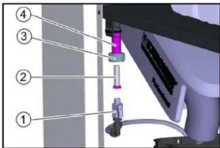
① Frost protection ball tap
② sieve
③ Union nut
④Holder
2. Pull the frost protection ball tap down.
3. Pull the sieve out of the holder and clean it.
4. Insert the sieve.
5. Fasten the frost protection ball tap to the holder with the union nut.
Cleaning the coin slot
-
Open the device door.
-
Open the coin acceptor.
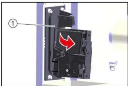
① Coin acceptor
3. Clean the coin track with a damp cloth with washing-up liquid.
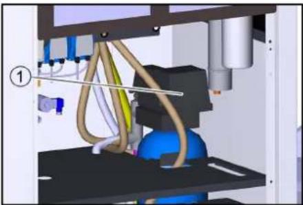
Manual regeneration WSO (BA 65/RO 75)
- Remove the control button cover.
natural_image
3D mechanical assembly diagram showing tubing and components inside a machine (no text or symbols visible)① Cover
- Press and hold the red button.

①Camshaft
②Red button
③"Salting and washing" position
3. Turn the camshaft by hand until the arrow points to "Salting and washing".
The regeneration process starts and takes about 1 hour.
Troubleshooting guide
△DANGER
Risk of fatal injury from electric shock.
Switch off the device at the on-site main power switch and secure against being switched on again before working on the device.
△WARNING
A high-pressure water jet can escape from damaged parts and cause injuries.
Depressurise the system by turning the power switch to "0/OFF" and then open all high-pressure guns until the pressure has been released from the system.
Who is permitted to eliminate faults?
Operator: Work labelled with "Operator" may only be performed by instructed persons capable of operating and maintaining high-pressure systems.
Qualified electrician: Work labelled with "Electrician" may only be performed by qualified electricians.
Customer Service: Work labelled with "Customer service" may only be performed by KÄRCHER customer service technicians or KÄRCHER-authorised technicians.
Currently applicable errors, faults and events
If there are critical faults, fault messages or events, the start screen automatically changes to the message view after approx. 1 minute.
An active message is indicated at the control by an attention symbol in the top right corner.
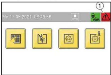
①Display in the event of existing messages
Message displays
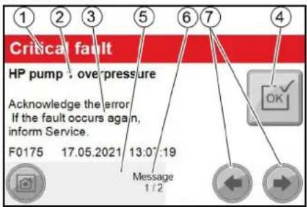
① Display message category:
— Red: critical fault; system stops immediately
— yellow: Malfunction; system can continue operating
— green: Event; information for the operator
② Error description
③Information on the possible cause of the fault and how to rectify it.
Display of fault number and date and time when the fault occurred.
④ Button for acknowledging the fault.
Note
If the button is greyed out, the fault still applies and cannot be acknowledged.
If the button has a yellow background, the malfunction has been rectified and the fault can be acknowledged.
⑤Progress bar, visualises how long the current message has already been displayed.
Note
The view switches to the next screen automatically after approx. 2-3 seconds. The progress bar has then finished.
⑥ Display current message number / total number of messages.
⑦Buttons for manually scrolling back and forth through the different message views.
Note
If there is a critical fault, the system cannot be operated. This is indicated by a red bar in the corresponding menu screen.
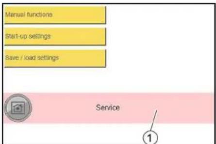
① Red bar when system is locked due to critical fault
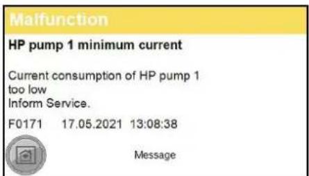
Malfunction display example
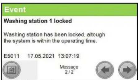
Event display example
Malfunctions indicated by the control
| Error number Cause Rectification | |||
| F0003 HP pump 1 connection. No CAN bus data connectionHP pump 1 Inform Service | |||
| F0004 HP pump 1 overload. Output overload HP pump 1 Inform Service | |||
| F0005 Remote control 1 connection. No CAN bus data connection Remote control 1 Inform Service | |||
| F0063 A39 connection. No CAN bus data connection Inform Service | |||
| F0064 A39 overload. Output overload A39 Inform Service | |||
| F0065 A40 connection. No CAN bus data connection Inform Service | |||
| F0066 A40 overload. Output overload A40 Inform Service | |||
| F0101 Exterior temp sensor defective Inform Service | |||
| F0170 | HP pump 1 overcurrent. Current consumption of HP pump 1 too high. | Acknowledge fault. Inform Service if fault occurs again. | |
| F0171 HP pump 1 minimum current. Current consumption of HP pump 1 too low Inform Service | |||
| F0172 | Relay / HP pump 1 contactor stuck. HP pump 1 electronics malfunction | Inform Service | |
| F0174 | HP pump 1 winding protect.contact | Acknowledge fault. Inform Service if fault occurs again. | |
| F0175 HP pump 1 overpressure | Acknowledge fault. Inform Service if fault occurs again. | ||
| F0176 | HP pump 1 oil level too low | Refill oil, Acknowledge malfunction | |
| F0190 Coin reset remote control 1 | Inform Service | ||
| F0191 Coin signal remote control 1 | At mechanical coin acceptor check the microswitch | ||
| F0570 Hot water shortage | Check the hot water supply | ||
| F0571 | Hot water overtemperature | Acknowledge fault. Inform Service if fault occurs again. | |
| F0572 Hot water temperature sensor defective | Inform Service | ||
| F0576 | No flow detected by flow monitor | Acknowledge fault. Inform Service if fault occurs again. | |
| F0577 | Flow monitor is defective | Acknowledge fault. Inform Service if fault occurs again. | |
| F0578 Automatic hot water circuit-breaker | Reset automatic circuit-breaker | ||
| F0610 | BA regeneration failed. Hardness sensor indicateshard water after regeneration. | Refill salt, acknowledge fault | |
| F0611 | BA regeneration failed. Regeneration of the bottle could not be started. | Inform Service | |
| F0612 Permeate buffer tank dry running. Have the tank filled up to the empty buffer tank level switch (maximum switch-on delay of 15 minutes) | Have the tank filled up to the empty buffer tank level switch (maximum switch-on delay of 15 minutes) | ||
| F0613 | Permeate buffer tank level switch. Empty and full buffer tank level switches switch simultaneously | check level switch. | |
| F0614 | Permeate buffer tank level switch. Empty and full buffer tank level switches switch simultaneously | check level switch. | |
| F0615 Water softening no water pressure | Check the water supply | ||
| F0616 On-site water treatment system | Check on-site water treatment system | ||
| F1125 | Controller Batterie Back-Up Batterie Of Controller Defective | Inform Service | |
Faults that are not displayed
Malfunctions at the high-pressure pump
| Malfunction | Possible cause | Rectification | By whom |
| System does not come up to pressure or the pump knocks | Water supply volume too low. | Check the water supply volume (see the Technical data). | Operator |
| High-pressure nozzle clogged or rinsed out. | Clean or replace the high-pressure nozzle. | Operator | |
| Incorrect high-pressure nozzle installed. | Replace the high-pressure nozzle (for size see "Technical data"). | Operator | |
| Line clogged. | Check that all lines are free. | Operator | |
| System draws in air. | Check the system for leaks, detergent suction hose must be inserted into the detergent, refill the detergent container. | Operator | |
| Check the pump hose for cracks and wear and replace if necessary. | Operator | ||
| High-pressure pump leaking (more than 3 drops of water per minute) | Defective pump component. | Replace the defective component. | Customer Service |
| Detergent not being sucked | Clogged filter or clogged hose. | Clean the parts. | Operator |
| Defective check valve. | Replace the valve. | Customer Service | |
| Pump hose in the dosing pump damaged. | Check the pump hose for cracks and wear and replace if necessary. | Operator, Customer Service | |
| High-pressure pump sucking air | Detergent container empty. | Fill with detergent. | Operator |
Malfunctions at the hot water generation
| Malfunction | Possible cause | Rectification | By whom |
| Water shortage in the hot water float tank | Water inlet blocked. | Open the fresh water stop valve (on site). | Operator |
| Float valve defective. Check the float valve, repair it if necessary | Operator | ||
| Dry running sensor defective. | Check the sensor. | Operator | |
| Hose burst or released. | Check hose lines, fasten or replace if necessary. | Operator | |
| System disconnection pump (optional) not working. | Check the pump. Check the power supply of the pump. | Customer Service | |
| Water temperature too high or too low | Hot water temperature sensor is defective. | Check the temperature sensor, replace it if necessary. | Customer Service |
Coin slot malfunctions
| Malfunction | Possible cause | Rectification | By whom |
| The coin acceptor rejects all coins | Trigger switched off. | Turn the trigger (in the device) to "1". | Operator |
| Time or operating times incorrectly set. | Check the settings at the control. | Operator | |
| A critical fault has deactivated the system. | Check the control for critical faults. Rectify and acknowledge possible faults. | Operator | |
| The coin acceptor is soiled. | Clean the coin slot (see "Care and maintenance"). | Operator |
Malfunctions at the base exchanger (option)
| Malfunction | Possible cause | Rectification | By whom |
| Base exchanger does not regenerate | No power supply. Check the power supply. Operator | ||
| Water remains hard after regeneration | Salt tank is empty. | Replenish softening salt, wait for the brine to form (approx. 2 hours), start manual regeneration. Never allow the salt level to fall below the water level in the salt tank. | Operator |
| Brine is not drawn in | Water inlet pressure too low. | Increase the water inlet pressure to at least 0.3 MPa (3 bar). | Operator |
Malfunctions at the base exchanger (option)
| Malfunction | Possible cause | Rectification | By whom |
| RO pump does not start | Permeate buffer tank is full. | Wait until permeate is consumed. | Operator |
| The start-up time of the control is not yet finished. | Wait. | Operator | |
| Water shortage. | Check the ultra-fine filter for contamination, replace the filter inlay if necessary. | Operator | |
| Base exchanger regeneration running. | Wait for the end of the regeneration. | Operator | |
| No softened water comes from the base exchanger. | Check the base exchanger. | Operator | |
| The permeate buffer tank is frequently empty | Water supply temperature too low. | Check the temperature of the softened water. | Operator |
Malfunctions at the frost protection devices (option)
| Malfunction | Possible cause | Rectification | By whom |
| Hot air blower not in operation | Hot air blower incorrectly adjusted. | Check the settings of the hot air blower (see "Frost protection/hot air blower"). | Operator |
| Frost protection not in operation | Voltage supply has been interrupted. | Check and ensure the power supply. | Operator |
| Cleaning tools frozen. | Frost protection pump filter or sieve clogged (antifreezing circulation only) | Open and clean the frost protection pump filter. Clean the sieve (see "Care and maintenance/Cleaning the sieve"). | Operator |
Technical data
| 500 l/h 6 kW | 500 l/h 12 kW | 500 l/h 24 kW | 900 l/h 6 kW | 900 l/h 12 kW | 900 l/h 24 kW | ||
| Country variant | |||||||
| Country | EU | EU | EU | EU | EU | EU | |
| Electrical connection | |||||||
| Mains voltage | V | 400 | 400 | 400 | 400 | 400 | 400 |
| Phase | ~ | 3 | 3 | 3 | 3 | 3 | 3 |
| Frequency | Hz | 50 | 50 | 50 | 50 | 50 | 50 |
| Connected load without frost protection | kW | 8,7 | 14,7 | 26,7 | 9,5 | 15,5 | 27,5 |
| Connected load, with frost protection | kW | 11,5 | 17,5 | 29,5 | 12,3 | 18,3 | 30,3 |
| Degree of protection | IPX5 | IPX5 | IPX5 | IPX5 | IPX5 | IPX5 | |
| Power protection (slow-blowing) | A | 32 | 40 | 63 | 32 | 40 | 63 |
| Residual current device | delta I, A | 0,03 | 0,03 | 0,03 | 0,03 | 0,03 | 0,03 |
| Water connection | |||||||
| Feed pressure | MPa | 0,6 | 0,6 | 0,6 | 0,6 | 0,6 | 0,6 |
| Input temperature (max.) | °C | 40 | 40 | 40 | 40 | 40 | 40 |
| Input amount (min.) | l/min | 10 | 10 | 10 | 15 | 15 | 15 |
| Device performance data | |||||||
| Nozzle size of standard nozzle | -- | 5004 | 5004 | 5004 | 5004 | 5004 | 5004 |
| Operating pressure | MPa | 10 | 10 | 10 | 10 | 10 | 10 |
| Operating pressure (max.) | MPa | 11 | 11 | 11 | 11 | 11 | 11 |
| Water flow rate | l/min | 9,16 | 9,16 | 9,16 | 9,16 | 9,16 | 9,16 |
| Hot water temperature during continuous operation | °C | 25 | 60 | 60 | 20 | 40 | 50 |
| High-pressure gun recoil force | N | 17 | 17 | 17 | 29 | 29 | 29 |
| Detergent flow rate | ml/min | 2,5...70 | 2,5...70 | 2,5...70 | 2,5...70 | 2,5...70 | 2,5...70 |
| Dimensions and weights | |||||||
| Length x width x height maximum | mm | 800x1200x2100 | 800x1200x2100 | 800x1200x2100 | 800x1200x2100 | 800x1200x2100 | 800x1200x2100 |
| Space for detergent canister | l | 4x10 | 4x10 | 4x10 | 4x10 | 4x10 | 4x10 |
| Cold water float tank | l | 3,5 | 3,5 | 3,5 | 3,5 | 3,5 | 3,5 |
| Hot water float tank | l | 30 | 30 | 30 | 30 | 30 | 30 |
| Weight | kg | 330 | 330 | 330 | 330 | 330 | 330 |
| Oil quantity of a high-pressure pump | l | 0,5 | 0,5 | 0,5 | 0,5 | 0,5 | 0,5 |
| Oil type | Type | SAE 90 | SAE 90 | SAE 90 | SAE 90 | SAE 90 | SAE 90 |
| Determined values in acc. with EN 60335-2-79 | |||||||
| Hand-arm vibration value | m/s2 | 0,2 | 0,2 | 0,2 | 0,2 | 0,2 | 0,2 |
| Uncertainty K | m/s2 | 0,5 | 0,5 | 0,5 | 0,5 | 0,5 | 0,5 |
| Sound pressure level | dB(A) | 66 | 66 | 66 | 66 | 66 | 66 |
| Uncertainty KpA | dB(A) | 3 | 3 | 3 | 3 | 3 | 3 |
| Sound power level LWA + K uncertaintyWA | dB(A) | 85 | 85 | 85 | 85 | 85 | 85 |
| Base exchanger | |||||||
| Capacity BA 42 | °dH/m3 | 42 | 42 | 42 | - | - | - |
| Capacity BA 65 | °dH/m3 | 65 | 65 | 65 | 65 | 65 | 65 |
| Water hardness of softened water | °dH | 0...0,3 | 0...0,3 | 0...0,3 | 0...0,3 | 0...0,3 | 0...0,3 |
| Salt tank | l | 35 | 35 | 35 | 35 | 35 | 35 |
| Reverseosmosis | |||||||
| Permeate capacity, min. at 15 °C water temperature | l/h | 60 | 60 | 60 | 60 | 60 | 60 |
| Operating pressure in new condition at 15 °C water temperature | MPa (bar) | 1,4 (14) | 1,4 (14) | 1,4 (14) | 1,4 (14) | 1,4 (14) | 1,4 (14) |
| Desalination rate | % | 98...99 | 98...99 | 98...99 | 98...99 | 98...99 | 98...99 |
| Water temperature range | °C | 2...30 | 2...30 | 2...30 | 2...30 | 2...30 | 2...30 |
| Ambient temperature (max.) | °C | 40 | 40 | 40 | 40 | 40 | 40 |
| Residual hardness of supply water | °dH | 0...0,3 | 0...0,3 | 0...0,3 | 0...0,3 | 0...0,3 | 0...0,3 |
| Maximum permeate conductivity for spotless drying | μS/cm | <100 | <100 | <100 | <100 | <100 | <100 |
| Permeate buffer tank | l | 65 | 65 | 65 | 65 | 65 | 65 |
Subject to technical modifications.
Warranty
The warranty conditions issued by our relevant sales company apply in all countries. We shall remedy possible malfunctions on your appliance within the warranty period free of cost, provided that a material or manufacturing defect is the cause. In a warranty case, please contact your dealer (with the purchase receipt) or the next authorised customer service site. (See overleaf for the address)
Transport
△CAUTION
Risk of injury, risk of damage
Be aware of the weight of the device during transportation.
- When transporting in vehicles, secure the device against slipping and tipping over according to the applicable guidelines.
Storage
△CAUTION
Risk of injury and damage
Be aware of the weight of the device during storage.
Accessories and spare parts
Only use original accessories and original spare parts. They ensure that the appliance will run fault-free and safely.
Information on accessories and spare parts can be found at www.kaercher.com.
Declaration of Conformity
EU Declaration of Conformity
We hereby declare that the machine described below complies with the relevant basic safety and health requirements in the EU Directives, both in its basic design and construction as well as in the version placed in circulation by us. This declaration is invalidated by any changes made to the machine that are not approved by us.
Product: High-pressure cleaner
Type: 1.319-xxx
Currently applicable EU Directives
2000/14/EC
2014/30/EU
2006/42/EC (+2009/127/EC)
2011/65/EU
2009/125/EC
Commission Regulation(s)
(EU) 2019/1781
Harmonised standards used
EN 60335-1
EN 60335-2
EN IEC 63000: 2018
EN 55014-1: 2017 + A11: 2020
EN 55014-2: 2015
EN 61000-3-2: 2014
EN 61000-3-3: 2013
EN 62233: 2008
Applied conformity evaluation method
2000/14/EG: Annex V
Sound power level dB(A)
1-station version
Measured: 82
Guaranteed: 85
2-Platz
Measured: 81
Guaranteed: 83
The signatories act on behalf of and with the authority of the company management.
H. Jenner
Chairman of the Board of Management
S. Reiser
Director Regulatory Affairs & Certification
Documentation supervisor:
S. Reiser
Alfred Kärcher SE & Co. KG
Alfred-Kärcher-Str. 28 - 40
71364 Winnenden (Germany)
Ph.: +49 7195 14-0
Fax: +49 7195 14-2212
Winnenden, 2021/06/01
Declaration of Conformity (UK)
We hereby declare that the product described below complies with the relevant provisions of the following
UK Regulations, both in its basic design and construction as well as in the version put into circulation by us. This declaration shall cease to be valid if the product is modified without our prior approval.
Product: High-pressure cleaner
Type: 1.319-xxx
Currently applicable UK Regulations
S.I. 2001/1701 (as amended)
S.I. 2016/1091 (as amended)
S.I. 2008/1597 (as amended)
S.I. 2012/3032 (as amended)
S.I. 2010/2617 (as amended)
Commission Regulation(s)
(EU) 2019/1781
Designated standards used
EN 60335-1
EN 60335-2-79
EN IEC 63000: 2018
EN 55014-1: 2017 + A11: 2020
EN 55014-2: 2015
EN 61000-3-2: 2014
EN 61000-3-3: 2013
EN 62233: 2008
Applied conformity assessment procedure
S.I. 2001/1701 (as amended): Schedule 8
Sound power level dB(A)
1-Platz
Measured: 82
Guaranteed: 85
2-Platz
Measured: 81
Guaranteed: 83
The signatories act on behalf of and with the authority of the company management.
H. Jenner
Chairman of the Board of Management
S. Reiser
Director Regulatory Affairs & Certification
Documentation supervisor:
S. Reiser
Alfred Kärcher SE & Co. KG
Alfred-Kärcher-Str. 28 - 40
71364 Winnenden (Germany)
Ph.: +49 7195 14-0
Fax: +49 7195 14-2212
Winnenden, 2021/06/01
Contenu
① Couvercle
② Réservoir de sel
natural_image
Interior view of a mechanical device with labeled component (1), showing internal components and wiring (no readable text or symbols)natural_image
3D mechanical assembly diagram showing tubing and components inside a machine (no text or symbols visible)①Couvercle
2006/42/CE (+2009/127/CE)
2011/65/EU
2009/125/CE
Ordonnance(s) appliquée(s) (UE) 2019/1781
H. Jenner
Chairman of the Board of Management
S. Reiser
Director Regulatory Affairs & Certification
Responsable de la documentation : S. Reiser
Alfred Kärcher SE & Co. KG
Alfred-Kärcher-Str. 28 - 40
71364 Winnenden (Germany)
Tél.: +49 7195 14-0
① Coperchio
② Serbatoio del sale
①Tasto menù "General"
② Tasto menù "Machine"
③Tasto menù "Wash-Program Settings"
④ Tasto menù "User Administration"
Menù User Administration
Menù Operation Hours Holidays
① Tasto menù "Holiday variable"
②Tasto menù "Holiday fix"
③ Tasto menù "Operation Hours"
Menù Operation Hours
Menù Maintenance Diagnostic
flowchart
graph TD
    A["Delete Fault History"] --> B{Do You Want To Delete Fault History?}
    B --> C["Yes"]
    B --> D["No"]
    C --> E["4"]
    D --> F["3"]
    D --> G["2"]
    D --> H["1"]
natural_image
Interior view of a medical or laboratory setup with numbered annotations (1 and 2) showing mechanical components and tubing (no readable text or symbols)natural_image
Interior view of a printer or printer unit with visible internal components and a numbered label (1), no readable text or symbols present.① Pompa ausiliaria
natural_image
3D mechanical assembly diagram showing tubing and components inside a machine (no text or symbols visible)①Coperchio
| Numero errore Causa Correzione | ||
| F0003 HP pump 1 connection. No CAN bus data connectionHP pump 1 Inform Service | ||
| F0004 HP pump 1 overload. Output overload HP pump 1 Inform Service | ||
| F0005 Remote control 1 connection. No CAN bus data connection Remote control 1 Inform Service | ||
| F0063 A39 connection. No CAN bus data connection Inform Service | ||
| F0064 A39 overload. Output overload A39 Inform Service | ||
| F0065 A40 connection. No CAN bus data connection Inform Service | ||
| F0066 A40 overload. Output overload A40 Inform Service | ||
| F0101 Exterior temp sensor defective Inform Service | ||
| F0170 | HP pump 1 overcurrent. Current consumption of HP pump 1 too high. | Acknowledge fault. Inform Service if fault occurs again. |
| F0171 HP pump 1 minimum current. Current consumption of HP pump 1 too low Inform Service | ||
| F0172 Relay / HP pump 1 contactor stuck. HP pump 1 electronics malfunction Inform Service | ||
| F0174 | HP pump 1 winding protect.contact | Acknowledge fault. Inform Service if fault occurs again. |
| F0175 | HP pump 1 overpressure | Acknowledge fault. Inform Service if fault occurs again. |
| F0176 | HP pump 1 oil level too low | Refill oil, Acknowledge malfunction |
| F0190 Coin reset remote control 1 | Inform Service | |
| F0191 | Coin signal remote control 1 | At mechanical coin acceptor check the microswitch |
| F0570 Hot water shortage | Check the hot water supply | |
| F0571 | Hot water overtemperature | Acknowledge fault. Inform Service if fault occurs again. |
| F0572 Hot water temperature sensor defective | Inform Service | |
| F0576 | No flow detected by flow monitor | Acknowledge fault. Inform Service if fault occurs again. |
| F0577 | Flow monitor is defective | Acknowledge fault. Inform Service if fault occurs again. |
| F0578 | Automatic hot water circuit-breaker | Reset automatic circuit-breaker |
| F0610 | BA regeneration failed. Hardness sensor indicateshard water after regeneration. | Refill salt, acknowledge fault |
| F0611 | BA regeneration failed. Regeneration of the bottle could not be started. | Inform Service |
| F0612 Permeate buffer tank dry running. Have the tank filled up to the empty buffer tank level switch (maximum switch-on delay of 15 minutes) | Have the tank filled up to the empty buffer tank level switch (maximum switch-on delay of 15 minutes) | |
| F0613 | Permeate buffer tank level switch. Empty and full buffer tank level switches switch simultaneously | check level switch. |
| F0614 | Permeate buffer tank level switch. Empty and full buffer tank level switches switch simultaneously | check level switch. |
| F0615 Water softening no water pressure | Check the water supply | |
| F0616 On-site water treatment system | Check on-site water treatment system | |
| F1125 | Controller Batterie Back-Up Batterie Of Controller Defective | Inform Service |
H. Jenner
Chairman of the Board of Management
S. Reiser
Director Regulatory Affairs & Certification
71364 Winnenden (Germany)
Tel.: +49 7195 14-0
Fax: +49 7195 14-2212
Winnenden, 01/06/2021
Inhoud
①Programmakeuzeschakelaar
Werkplek
① Apparaatschakelaar
② Slot
③Deur
4. Open de deur.
5. De apparaatschakelaar op "1/ON" zetten.
6. Deuren dicht.
Bediening
Wasprogramma's
① Wasprogrammaschakelaar
STOP
①Reinigingsborstel
② Borghendel
③ Hogedrukpistool
④Triggerhendel
⑤ Beveiligingspal
① Deksel
② Zoutreservoir
① Touchscreen
②Elektrokast
flowchart
graph TD
    A["0,36 / 65 Sek"] --> B["High-Pressure Wash"]
    B --> C["Enabling of washing station"]
    B --> D["Heating remain control"]
    C --> E["Washing"]
    D --> E
    E --> F["⑤"]
    E --> G["④"]
    E --> H["③"]
    E --> I["②"]
    E --> J["①"]
① Menuknop "General"
② Menuknop "Machine"
③ Menuknop "Wash-Program Settings"
④ Menuknop "User Administration"
Menu User Administration
①Toets "Service"
② Toets "Owner"
③Toets "Operator"
① Menuknop "Lock"
② Menuknop "Coin value"
③ Menuknop "Components"
Menu Components
② Menuknop "Language"
③ Menuknop "Operation Hours Holidays"
④ Menuknop "Date Time"
Menu Date Time
Menu Operation Hours Holidays
① Menuknop "Holiday variable"
② Menuknop "Holiday fix"
③ Menuknop "Operation Hours"
Menu Operation Hours
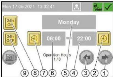
① Menuknop "Maintenance Diagnostic"
② Menuknop "Operating Hours"
③ Menuknop "Turnover"
Menu Turnover
① Dagomzet wissen
② Bent u zeker dat u de dagomzet wilt wissen?
③ Nee
④Ja
Menu Operating Hours
① Menuknop "Event History"
② Menuknop "Fault History"
③ Menuknop "System Information"
④ Menuknop "Interval"
Menu Interval
flowchart
graph TD
    A["Delete Fault History"] --> B{Do You Want To Delete Fault History?}
    B --> C["Yes"]
    B --> D{No}
    C --> E["④"]
    D --> F["③"]
    D --> G["②"]
    D --> H["①"]
① Symbool Vorstbescherming
②Thermostaatregelaar
③ Vermogensregelaar
natural_image
Interior view of a printer or printer unit with visible internal components and a numbered label (1), no readable text or symbols present.①Boosterpomp
①Olieaftapplug
② Oliereservoir
③Deksel
①Kogelkraan vorstbescherming
②Zeef
③Wartelmoer
④Houder
①Munttester
natural_image
3D mechanical assembly diagram showing hoses and components inside a machine (no text or labels visible)①Deksel
| Foutnummer Oorzaak Oplossing | ||
| F0003 HP pump 1 connection. No CAN bus data connectionHP pump 1 Inform Service | ||
| F0004 HP pump 1 overload. Output overload HP pump 1 Inform Service | ||
| F0005 Remote control 1 connection. No CAN bus data connection Remote control 1 Inform Service | ||
| F0063 A39 connection. No CAN bus data connection Inform Service | ||
| F0064 A39 overload. Output overload A39 Inform Service | ||
| F0065 A40 connection. No CAN bus data connection Inform Service | ||
| F0066 A40 overload. Output overload A40 Inform Service | ||
| F0101 Exterior temp sensor defective Inform Service | ||
| F0170 HP pump 1 overcurrent. Current consumption of HP pump 1 too high. | Acknowledge fault. Inform Service if fault occurs again. | |
| F0171 HP pump 1 minimum current. Current consumption of HP pump 1 too low Inform Service | ||
| F0172 Relay / HP pump 1 contactor stuck. HP pump 1 electronics malfunction | Inform Service | |
| F0174 HP pump 1 winding protectcontact | Acknowledge fault. Inform Service if fault occurs again. | |
| F0175 HP pump 1 overpressure | Acknowledge fault. Inform Service if fault occurs again. | |
| F0176 HP pump 1 oil level tool low Refill oil, Acknowledgementallfunction | ||
| F0190 Coin reset remote control 1 Inform Service | ||
| F0191 Coin signal remote control 1 | At mechanical coin acceptor check the microswitch | |
| F0570 Hot water shortage Check the hot water supply | ||
| F0571 Hot water overtemperature | Acknowledge fault. Inform Service if fault occurs again. | |
| F0572 Hot water temperature sensor defective Inform Service | ||
| F0576 No flow detected by flow monitor | Acknowledge fault. Inform Service if fault occurs again. | |
| F0577 Flow monitor is defective | Acknowledge fault. Inform Service if fault occurs again. | |
| F0578 Automatic hot water circuit-breaker Reset automatic circuit-breaker | ||
| F0610 BA regeneration failed. Hardness sensor indicateshard water after regeneration. | Refill salt, acknowledge fault | |
| F0611 BA regeneration failed. Regeneration of the bottle could not be started. Inform Service | ||
| F0612 Permeate buffer tank dry running. Have the tank filled up to the empty buffer tank level switch(maximum switch-on delay of 15 minutes) | Have the tank filled up to the empty buffer tank level switch (maximum switch-on delay of 15 minutes) | |
| F0613 Permeate buffer tank level switch. Empty and full buffer tank level switches switch simultaneously | check level switch. | |
| F0614 Permeate buffer tank level switch. Empty and full buffer tank level switches switch simultaneously | check level switch. | |
| F0615 Water softening no water pressure Check the water supply | ||
| F0616 On-site water treatment system Check on-site water treatment system | ||
| F1125 Controller Batterie Back-Up Batterie Of Controller Defective | Inform Service | |
H. Jenner
Chairman of the Board of Management
S. Reiser
Director Regulatory Affairs & Certification
71364 Winnenden (Germany)
Tel.: +49 7195 14-0
Fax: +49 7195 14-2212
Winnenden, 2021/06/01
① Selector de programas
Puesto de trabajo
- Dureza total: < 28 °dH, < 50° TH, < 500 ppm (mg CaCO₃/l)
• Hierro: < 0,5 mg/l
• Manganeso: <0,05 mg/l
• Cobre: <2 mg/l
①Interruptor del programa de lavado
STOP
① Selector de programas
①Tapa
② Depósito de sal
① Tecla de dureza
② Tecla de sal
③ Tecla de tiempo
④Pantalla
① Pantalla táctil
② Caja eléctrica
①Teclado
②Campo de entrada
③ Confirmar entrada
④ Eliminar entrada
① Tecla de menú «Sistema»
flowchart
graph TD
    A["Delete Fault History"] --> B{Do You Want To Delete Fault History?}
    B --> C["Yes"]
    B --> D{No}
    C --> E["4"]
    D --> F["3"]
    D --> G["2"]
    D --> H["1"]
natural_image
Interior view of a printer or printer unit with visible internal components and a numbered label (1), no readable text or symbols present.①Monedero
natural_image
3D mechanical assembly diagram showing tubing and components inside a machine (no text or symbols visible)①Tapa
2006/42/CE (+2009/127/CE)
2011/65/UE
2009/125/CE
H. Jenner
Chairman of the Board of Management
S. Reiser
Director Regulatory Affairs & Certification
71364 Winnenden (Germany)
Tel.: +49 7195 14-0
Fax: +49 7195 14-2212
Winnenden, 01/06/2021
Indice
① Selector do programa
Local de trabalho
- Dureza total: < 28 °dH, < 50° TH, < 500 ppm (mg CaCO₃/l)
- Ferro: < 0,5 mg/l
• Manganésio: < 0,05 mg/l
• Cobre: < 2 mg/l
① Selector do programa
①Tampa
② Depósito de sal
①Tecla de dureza
②Tecla de sal
③Teda de tempo
④ Display
⑤ Cabeça de comando do permutador básico
①Ecrã tátil
②Caixa eléctrica
① Tecla do menu "General"
② Tecla do menu "Machine"
③ Tecla do menu "Wash-Program Settings"
④ Tecla do menu "User Administration"
Menu User Administration
①Tecla "Service"
② Tecla "Owner"
③Tecla "Operator"
Menu Operation Hours Holidays
flowchart
graph TD
    A["Delete Fault History"] --> B{Do You Want To Delete Fault History?}
    B --> C["Yes"]
    B --> D{No}
    C --> E["4"]
    D --> F["3"]
    D --> G["2"]
    D --> H["1"]
natural_image
Interior view of a printer or printer unit with visible internal components and a numbered label (1), no readable text or symbols present.①Moedeiro
natural_image
3D mechanical assembly diagram showing tubing and components inside a machine (no text or symbols visible)①Tampa
HP pump 1 minimum current
Current consumption of HP pump 1 too low Inform Service.
F0171 17.05.2021 13:08:38

Message
Washing station 1 locked
Washing station has been locked, although the system is within the operating time.
E5011 17.05.2021 13:07:19

Message
2/2


| Número do erro Causa Eliminação | |||
| F0003 HP pump 1 connection. No CAN bus data connectionHP pump 1 Inform Service | |||
| F0004 HP pump 1 overload. Output overload HP pump 1 Inform Service | |||
| F0005 Remote control 1 connection. No CAN bus data connection Remote control 1 Inform Service | |||
| F0063 A39 connection. No CAN bus data connection Inform Service | |||
| F0064 A39 overload. Output overload A39 Inform Service | |||
| F0065 A40 connection. No CAN bus data connection Inform Service | |||
| F0066 A40 overload. Output overload A40 Inform Service | |||
| F0101 Exterior temp sensor defective Inform Service | |||
| F0170 | HP pump 1 overcurrent. Current consumption of HP pump 1 too high. | Acknowledge fault. Inform Service if fault occurs again. | |
| F0171 HP pump 1 minimum current. Current consumption of HP pump 1 too low Inform Service | |||
| F0172 | Relay / HP pump 1 contactor stuck. HP pump 1 electronics malfunction | Inform Service | |
| F0174 | HP pump 1 winding protect.contact | Acknowledge fault. Inform Service if fault occurs again. | |
| F0175 HP pump 1 overpressure Acknowledge fault. Inform Service if fault occurs again. | |||
| F0176 | HP pump 1 oil level too low | Refill oil, Acknowledge malfunction | |
| F0190 Coin reset remote control 1 Inform Service | |||
| F0191 Coin signal remote control 1 At mechanical coin acceptor check the microswitch | |||
| F0570 Hot water shortage Check the hot water supply | |||
| F0571 Hot water overtemperature Acknowledge fault. Inform Service if fault occurs again. | |||
| F0572 Hot water temperature sensor defective Inform Service | |||
| F0576 | No flow detected by flow monitor | Acknowledge fault. Inform Service if fault occurs again. | |
| F0577 Flow monitor is defective Acknowledge fault. Inform Service if fault occurs again. | |||
| F0578 Automatic hot water circuit-breaker Reset automatic circuit-breaker | |||
| F0610 | BA regeneration failed. Hardness sensor indicateshard water after regeneration. | Refill salt, acknowledge fault | |
| F0611 | BA regeneration failed. Regeneration of the bottle could not be started. | Inform Service | |
| F0612 Permeate buffer tank dry running. Have the tank filled up to the empty buffer tank level switch (maximum switch-on delay of 15 minutes) | Have the tank filled up to the empty buffer tank level switch (maximum switch-on delay of 15 minutes) | ||
| F0613 | Permeate buffer tank level switch. Empty and full buffer tank level switches switch simultaneously | check level switch. | |
| F0614 | Permeate buffer tank level switch. Empty and full buffer tank level switches switch simultaneously | check level switch. | |
| F0615 Water softening no water pressure Check the water supply | |||
| F0616 | On-site water treatment system | Check on-site water treatment system | |
| F1125 | Controller Batterie Back-Up Batterie Of Controller Defective | Inform Service | |
2006/42/CE (+2009/127/CE)
2011/65/UE
2009/125/CE
S. Reiser
Chairman of the Board of Management
Director Regulatory Affairs & Certification
①Programvalgbryter
Arbeidsplass
① Apparatbryter
②Làs
③Dør
4. Åpne døren.
5. Skru apparatbryteren på 1/ON.
6. Lukk døren.
Betjening
Vaskeprogrammer
Det aktive vaskeprogrammet velges med vaskeprogrambryteren.
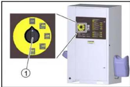
① Vaskeprogrambryter
STOP
Programmet avbrytes.
①Deksel
②Salttank
-
Fyll salttanken helt opp med avherdersalt.
-
Sett på lokket på salttanken.
Merknad
En tom salttank vil forårsake en funksjonsfeil. Fyll salt-anken senest när vann er synlig i salttanken när lokket er fjernet.
①Hardhetstast
②Salttast
③Tidstast
④Display
⑤Styrehode baseveksler
① Berøringsskjerm
②Elboks
① Menytasten «General»
② Menytasten «Machine»
③ Menytasten «Wash-Program Settings»
④ Menytasten «User Administration»
Meny User Administration
Kode standardinnstilling Owner: 1234
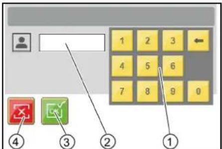
①Tastatur
②Inntastingsfelt
③ Bekrefte inntastingen
① Menytast "..."
①Tast Neste vindu
②Tast Endre vaskeprogram
③Tast Forrige vindu
④Vindu 1 av 2
⑤ Vaskeprogram betegnelse
Endre parametere for et vaskeprogram
①Tasten Endre tallverdi
② Varmlvannstemperatur i °C
③Meny Components
④ Hot water temperature
Meny Coin value
I menyen Coin value blir vaskeverdien for 100 % programkjøringstid samt myntverdiene for de individuelle kanalene til myntvalidatoren stilt inn.
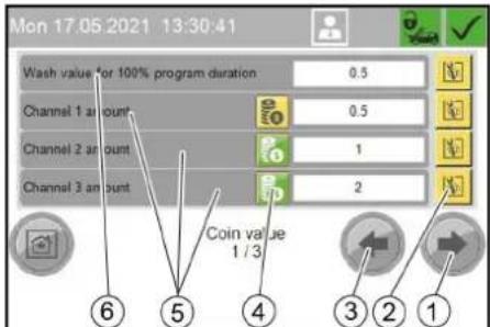
①Tasten Endre innstilling
② Sperre vaskeplass 1
①Tasten Sperre vaskeplass
②Tasten Opphev sperring
Meny Operation Hours Holidays
Meny Operation Hours
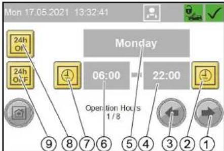
① Tasten En ukedag fremover
②Angi Stille inn driftsslutt
③ Tasten En ukedag bakover
④Klokkeslett driftsslutt
⑤Ukedag (mandag-søndag, helligdag)
⑥Klokkeslett driftsstart
⑦Tasten Stille inn driftsstart
⑧Tasten Apent hele dagen
⑨Tasten Stengt hele dagen
Meny Holiday fix
① Slett daglig omsetning
②Vil du virkelig slette den daglige omsetningen?
③Nei
④Ja
Meny Operating Hours
I menyen Operating Hours vises driftstiden for de enkelte anleggskomponentene og de enkelle vaskeprogrammene.
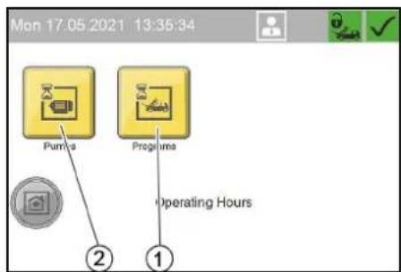
① Menytasten «Programs», driftstimer for vaskeprogrammer
② Menytasten «Pumps», driftstimer for anleggskomponenter
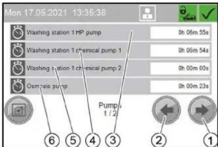
Driftstimer for anleggskomponenter
①Tasten Neste vindu
②Tasten Forrige vindu
③ Driftstimer høytrykkspumpe
④ Driftstimer doseringspumpe 1
⑤ Driftstimer doseringspumpe 2
⑥ Driftstimer pumpe RO (tilleggsalternativ)
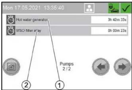
①Tasten Neste vindu
②Tasten Forrige vindu
flowchart
graph TD
    A["Delete Fault History"] --> B{Do You Want To Delete Fault History?}
    B --> C["Yes"]
    B --> D{No}
    C --> E["④"]
    D --> F["③"]
    D --> G["②"]
    D --> H["①"]
①Frostbeskyttelsessymbol
②Termostatregulator
③Effektregulator
①Trykkøkningspumpe
Ta ut av drift
- Skru apparatbryteren på «0/OFF».
① Oljeplugg
② Oljebeholder
③Deksel
- Ta av lokket på oljebeholderen.
- Skru ut oljepluggen og samle opp oljen.
- Skru inn oljepluggen og trekk den til.
- Fyll på ny olje langsomt opp til merket «MAX» i olje- beholderen.
- Sett på lokket på oljebeholderen.
- Spillolje må avfallsbehandles på miljømessig korrekt måte eller leveres til en miljøstasjon.
Rengjør silen
- Äpne overfalsmutteren.
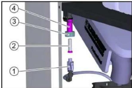
natural_image
3D printer internal structure showing hoses and wiring (no text or symbols visible)①Deksel
| Feilnummer Årsak Utbedring | |||
| F0003 HP pump 1 connection. No CAN bus data connectionHP pump 1 Inform Service | |||
| F0004 HP pump 1 overload. Output overload HP pump 1 Inform Service | |||
| F0005 Remote control 1 connection. No CAN bus data connection Remote control 1 Inform Service | |||
| F0063 A39 connection. No CAN bus data connection Inform Service | |||
| F0064 A39 overload. Output overload A39 Inform Service | |||
| F0065 A40 connection. No CAN bus data connection Inform Service | |||
| F0066 A40 overload. Output overload A40 Inform Service | |||
| F0101 Exterior temp sensor defective Inform Service | |||
| F0170 | HP pump 1 overcurrent. Current consumption of HP pump 1 too high. | Acknowledge fault. Inform Service if fault occurs again. | |
| F0171 HP pump 1 minimum current. Current consumption of HP pump 1 too low Inform Service | |||
| F0172 | Relay / HP pump 1 contactor stuck. HP pump 1 electronics malfunction | Inform Service | |
| F0174 HP pump 1 winding protect.contact Acknowledge fault. Inform Service if fault occurs | again. | ||
| F0175 HP pump 1 overpressure | Acknowledge fault. Inform Service if fault occurs again. | ||
| F0176 | HP pump 1 oil level too low | Refill oil, Acknowledge malfunction | |
| F0190 Coin reset remote control 1 | Inform Service | ||
| F0191 Coin signal remote control 1 | At mechanical coin acceptor check the micro-switch | ||
| F0570 Hot water shortage | Check the hot water supply | ||
| F0571 Hot water overtemperature | Acknowledge fault. Inform Service if fault occurs again. | ||
| F0572 Hot water temperature sensor defective | Inform Service | ||
| F0576 | No flow detected by flow monitor | Acknowledge fault. Inform Service if fault occurs again. | |
| F0577 Flow monitor is defective | Acknowledge fault. Inform Service if fault occurs again. | ||
| F0578 Automatic hot water circuit-breaker | |||
| F0610 | BA regeneration failed. Hardness sensor indicateshard water after regeneration. | Refill salt, acknowledge fault | |
| F0611 | BA regeneration failed. Regeneration of the bottle could not be started. | Inform Service | |
| F0612 | Permeate buffer tank dry running. Have the tank filled up to the empty buffer tank level switch (maximum switch-on delay of 15 minutes) | Have the tank filled up to the empty buffer tank level switch (maximum switch-on delay of 15 minutes) | |
| F0613 | Permeate buffer tank level switch. Empty and full buffer tank level switches switch simultaneously | check level switch. | |
| F0614 | Permeate buffer tank level switch. Empty and full buffer tank level switches switch simultaneously | check level switch. | |
| F0615 Water softening no water pressure | Check the water supply | ||
| F0616 On-site water treatment system | Check on-site water treatment system | ||
| F1125 | Controller Batterie Back-Up Batterie Of Controller Defective | Inform Service | |
Feil uten visning
2006/42/EF (+2009/127/EF)
2011/65/EU
2009/125/EF
2000/14/EF: Vedlegg V
Lydeffektnivå dB(A)
1- plass
Målt: 82
Garantert: 85
2-Platz
Målt: 81
Garantert: 83
H. Jenner
Chairman of the Board of Management
S. Reiser
Director Regulatory Affairs & Certification
71364 Winnenden (Germany)
Tlf.: +49 7195 14-0
Winnenden, 2021/06/01
Innehåll
Allmän information 124
Miljöskydd 124
Säkerhetsinformation 124
①Programväljare
Arbetsplats
① Programväljare
① Rengöringsborste
②Låsknapp
③ Spolhandtag
④ Avdragsspak
⑤ Säkerhetsspärr
①Lock
② Saltbehållare
①Pekskärm
②Elbox
①Menyknapp "General"
② Menyknapp "Machine"
③Menyknapp "Wash-Program Settings"
④ Menyknapp "User Administration"
① Menyknapp "Lock"
② Menyknapp "Coin value"
③ Menyknapp "Components"
Meny Components
Meny Operation Hours Holidays
① Menyknapp "Holiday variable"
② Menyknapp "Holiday fix"
③Menyknapp "Operation Hours"
Meny Operation Hours
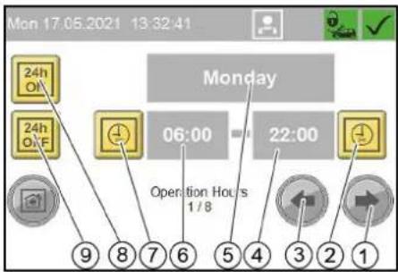
①Menyknapp "Maintenance Diagnostic"
②Menyknapp "Operating Hours"
③Menyknapp "Turnover"
Meny Turnover
① Menyknapp "Event History"
②Menyknapp "Fault History"
③Menyknapp "System Information"
④Menyknapp "Interval"
Meny Interval
① Knapp Radera felminne
②Felbeskrivning
③ Tidpunkt för felmeddelande
④ Felnummer
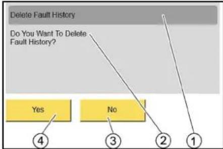
flowchart
graph TD
    A["Delete Fault History"] --> B{Do You Want To Delete Fault History?}
    B --> C["Yes"]
    B --> D{No}
    C --> E["4"]
    D --> F["3"]
    D --> G["2"]
    D --> H["1"]
① Radera felminne
②Vill du verkligen radera felminnet?
③ Nej
④Ja
Meny Event History
① Magnetventil frostskydd
② Kulventil frostskydd
natural_image
Interior view of a printer or printer unit with visible paper sheets and a labeled component (no text or symbols)① Kulventil frostskydd
② Sil
③ Kopplingsmutter
④Hàllare
natural_image
3D mechanical assembly diagram showing tubing and components inside a machine (no text or symbols visible)①Lock
HP pump 1 minimum current
Current consumption of HP pump 1
too low
Inform Service.
F0171 17.05.2021 13:08:38

Message
Exempel på indikering Störning
Event
Washing station 1 locked
Washing station has been locked, although the system is within the operating time.
E5011 17.05.2021 13:07:19

Message
212


| Felnummer Orsak Atgård | ||
| F0003 HP pump 1 connection. No CAN bus data connectionHP pump 1 Inform Service | ||
| F0004 HP pump 1 overload. Output overload HP pump 1 Inform Service | ||
| F0005 Remote control 1 connection. No CAN bus data connection Remote control 1 Inform Service | ||
| F0063 A39 connection. No CAN bus data connection Inform Service | ||
| F0064 A39 overload. Output overload A39 Inform Service | ||
| F0065 A40 connection. No CAN bus data connection Inform Service | ||
| F0066 A40 overload. Output overload A40 Inform Service | ||
| F0101 Exterior temp sensor defective Inform Service | ||
| F0170 | HP pump 1 overcurrent. Current consumption of HP pump 1 too high. | Acknowledge fault. Inform Service if fault occurs again. |
| F0171 HP pump 1 minimum current. Current consumption of HP pump 1 too low Inform Service | ||
| F0172 | Relay / HP pump 1 contactor stuck. HP pump 1 electronics malfunction | Inform Service |
| F0174 | HP pump 1 winding protect.contact | Acknowledge fault. Inform Service if fault occurs again. |
| F0175 HP pump 1 overpressure | Acknowledge fault. Inform Service if fault occurs again. | |
| F0176 | HP pump 1 oil level too low | Refill oil, Acknowledge malfunction |
| F0190 Coin reset remote control 1 | Inform Service | |
| F0191 Coin signal remote control 1 | At mechanical coin acceptor check the microswitch | |
| F0570 Hot water shortage | Check the hot water supply | |
| F0571 Hot water overtemperature | Acknowledge fault. Inform Service if fault occurs again. | |
| F0572 Hot water temperature sensor defective | Inform Service | |
| F0576 | No flow detected by flow monitor | Acknowledge fault. Inform Service if fault occurs again. |
| F0577 Flow monitor is defective | Acknowledge fault. Inform Service if fault occurs again. | |
| F0578 Automatic hot water circuit-breaker | Reset automatic circuit-breaker | |
| F0610 | BA regeneration failed. Hardness sensor indicateshard water after regeneration. | Refill salt, acknowledge fault |
| F0611 | BA regeneration failed. Regeneration of the bottle could not be started. | Inform Service |
| F0612 Permeate buffer tank dry running. Have the tank filled up to the empty buffer tank level switch (maximum switch-on delay of 15 minutes) | Have the tank filled up to the empty buffer tank level switch (maximum switch-on delay of 15 minutes) | |
| F0613 | Permeate buffer tank level switch. Empty and full buffer tank level switches switch simultaneously | check level switch. |
| F0614 | Permeate buffer tank level switch. Empty and full buffer tank level switches switch simultaneously | check level switch. |
| F0615 Water softening no water pressure | Check the water supply | |
| F0616 On-site water treatment system | Check on-site water treatment system | |
| F1125 | Controller Batterie Back-Up Batterie Of Controller Defective | Inform Service |
H. Jenner
Chairman of the Board of Management
S. Reiser
Director Regulatory Affairs & Certification
D-71364 Winnenden (Germany)
Tfn: +49 7195 14-0
Fax: +49 7195 14-2212
Winnenden, 01.06.2021
Sisältö
- Kloridit: < 300 mg/
① Laitekytkin
② Lukko
③Ovi
flowchart
graph TD
    A["0,36 / 65 Sek"] --> B["High-Pressure Wash 90s / 0,50"]
    B --> C["Enabling of washing station"]
    B --> D["Heating remote control"]
    C --> E["Washing"]
    D --> E
    E --> F["⑤"]
    E --> G["④"]
    E --> H["③"]
    E --> I["②"]
    E --> J["①"]
①Valikkopainike "General"
②Valikkopainike "Machine"
③Valikkopainike "Wash-Program Settings"
④ Valikkopainike "User Administration"
Valikko User Administration
① Painike "Service"
②Painike "Owner"
③Painike "Operator"
① Valikkopainike "..."
①Valikkopainike "Lock"
② Valikkopainike "Coin value"
③ Valikkopainike "Components"
Valikko Components
② Valikkopainike "Language"
③ Valikkopainike "Operation Hours Holidays"
④ Valikkopainike "Date Time"
Valikko Date Time
Valikko Operation Hours Holidays
①Valikkopainike "Holiday variable"
② Valikkopainike "Holiday fix"
③ Valikkopainike "Operation Hours"
Valikko Operation Hours
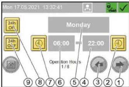
Valikko General Info
①Valikkopainike "Maintenance Diagnostic"
② Valikkopainike "Operating Hours"
③Valikkopainike "Turnover"
Valikko Turnover
①Valikkopainike "Daily turnover"
②Valikkopainike "Total turnover"
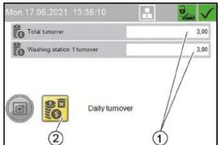
Päivän liikevaihto
Valikko Operating Hours
Valikko Maintenance Diagnostic
① Valikkopainike "Event History"
②Valikkopainike "Fault History"
③Valikkopainike "System Information"
④Valikkopainike "Interval"
Valikko Interval
Valikko Fault History
flowchart
graph TD
    A["Delete Fault History"] --> B{Do You Want To Delete Fault History?}
    B --> C["Yes"]
    B --> D["No"]
    C --> E["4"]
    D --> F["3"]
    D --> G["2"]
    D --> H["1"]
Valikko Event History
natural_image
Interior view of a printer or printer assembly showing internal components and a labeled component (no text or symbols visible)natural_image
3D mechanical assembly diagram showing tubing and components inside a machine (no text or symbols visible)①Kansi
| Virheen numero Syy Korjaus | ||
| F0003 HP pump 1 connection. No CAN bus data connectionHP pump 1 Inform Service | ||
| F0004 HP pump 1 overload. Output overload HP pump 1 Inform Service | ||
| F0005 Remote control 1 connection. No CAN bus data connection Remote control 1 Inform Service | ||
| F0063 A39 connection. No CAN bus data connection Inform Service | ||
| F0064 A39 overload. Output overload A39 Inform Service | ||
| F0065 A40 connection. No CAN bus data connection Inform Service | ||
| F0066 A40 overload. Output overload A40 Inform Service | ||
| F0101 Exterior temp sensor defective Inform Service | ||
| F0170 | HP pump 1 overcurrent. Current consumption of HP pump 1 too high. | Acknowledge fault. Inform Service if fault occurs again. |
| F0171 HP pump 1 minimum current. Current consumption of HP pump 1 too low Inform Service | ||
| F0172 | Relay / HP pump 1 contactor stuck. HP pump 1 electronics malfunction | Inform Service |
| F0174 | HP pump 1 winding protect.contact | Acknowledge fault. Inform Service if fault occurs again. |
| F0175 HP pump 1 overpressure Acknowledge fault. Inform Service if fault occurs again. | ||
| F0176 | HP pump 1 oil level too low | Refill oil, Acknowledge malfunction |
| F0190 Coin reset remote control 1 Inform Service | ||
| F0191 Coin signal remote control 1 At mechanical coin acceptor check the microswitch | ||
| F0570 Hot water shortage Check the hot water supply | ||
| F0571 Hot water overtemperature Acknowledge fault. Inform Service if fault occurs again. | ||
| F0572 Hot water temperature sensor defective Inform Service | ||
| F0576 | No flow detected by flow monitor | Acknowledge fault. Inform Service if fault occurs again. |
| F0577 Flow monitor is defective Acknowledge fault. Inform Service if fault occurs again. | ||
| F0578 Automatic hot water circuit-breaker Reset automatic circuit-breaker | ||
| F0610 | BA regeneration failed. Hardness sensor indicateshard water after regeneration. | Refill salt, acknowledge fault |
| F0611 | BA regeneration failed. Regeneration of the bottle could not be started. | Inform Service |
| F0612 Permeate buffer tank dry running. Have the tank filled up to the empty buffer tank level switch (maximum switch-on delay of 15 minutes) | Have the tank filled up to the empty buffer tank level switch (maximum switch-on delay of 15 minutes) | |
| F0613 | Permeate buffer tank level switch. Empty and full buffer tank level switches switch simultaneously | check level switch. |
| F0614 | Permeate buffer tank level switch. Empty and full buffer tank level switches switch simultaneously | check level switch. |
| F0615 Water softening no water pressure Check the water supply | ||
| F0616 On-site water treatment system Check on-site water treatment system | ||
| F1125 | Controller Batterie Back-Up Batterie Of Controller Defective | Inform Service |
H. Jenner
Chairman of the Board of Management
S. Reiser
Director Regulatory Affairs & Certification
71364 Winnenden (Germany)
Puh.: +49 7195 14-0


①Нистящая щетка
② Фиксирующий рычаг
flowchart
graph TD
    A["Delete Fault History"] --> B{Do You Want To Delete Fault History?}
    B --> C["Yes"]
    B --> D{No}
    C --> E["4"]
    D --> F["3"]
    D --> G["2"]
    D --> H["1"]
natural_image
Interior view of a printer or printer unit with visible internal components and a numbered annotation (1), no readable text or symbols present.natural_image
3D mechanical assembly diagram showing tubing and components inside a machine (no text or symbols visible)①Крышка
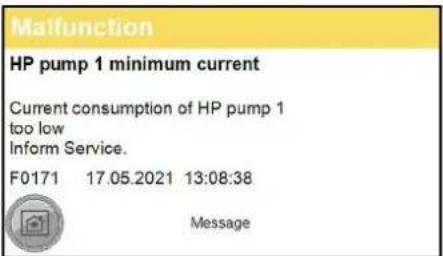
| Номер ошибки | Причина | Способ устранения |
| F0003 HP pump 1 connection | on. No CAN bus data connectionHP pump 1 Inform Service | |
| F0004 HP pump 1 overload | Output overload HP pump 1 Inform Service | |
| F0005 Remote control 1 connection. No CAN bus data connection Remote control 1 Inform Service | ||
| F0063 A39 connection. No | CAN bus data connection Inform Service | |
| F0064 A39 overload. Output overload A39 Inform Service | ||
| F0065 A40 connection. No | CAN bus data connection Inform Service | |
| F0066 A40 overload. Output overload A40 Inform Service | ||
| F0101 Exterior temp sensor defective Inform Service | ||
| F0170 | HP pump 1 overcurrent. Current consumption of HP pump 1 too high. | Acknowledge fault. Inform Service if fault occurs again. |
| F0171 HP pump 1 minimum current. Current consumption of HP pump 1 too low Inform Service | ||
| F0172 Relay / HP pump 1 contactor stuck. HP pump 1 electronics malfunction | Inform Service | |
| F0174 | HP pump 1 winding protect.contact | Acknowledge fault. Inform Service if fault occurs again. |
| F0175 | HP pump 1 overpressure | Acknowledge fault. Inform Service if fault occurs again. |
| F0176 | HP pump 1 oil level too low | Refill oil, Acknowledge malfunction |
| F0190 Coin reset remote control 1 | Inform Service | |
| F0191 | Coin signal remote control 1 | At mechanical coin acceptor check the microswitch |
| F0570 Hot water shortage | Check the hot water supply | |
| F0571 | Hot water overtemperature | Acknowledge fault. Inform Service if fault occurs again. |
| F0572 Hot water temperature sensor defective | Inform Service | |
| F0576 | No flow detected by flow monitor | Acknowledge fault. Inform Service if fault occurs again. |
| F0577 | Flow monitor is defective | Acknowledge fault. Inform Service if fault occurs again. |
| F0578 Automatic hot water circuit-breaker | Reset automatic circuit-breaker | |
| F0610 | BA regeneration failed. Hardness sensor indicateshard water after regeneration. | Refill salt, acknowledge fault |
| F0611 | BA regeneration failed. Regeneration of the bottle could not be started. | Inform Service |
| F0612 Permeate buffer tank dry running. Have the tank filled up to the empty buffer tank level switch (maximum switch-on delay of 15 minutes) | Have the tank filled up to the empty buffer tank level switch (maximum switch-on delay of 15 minutes) | |
| F0613 Permeate buffer tank level switch. Empty and full buffer tank level switches switch simultaneously | check level switch. | |
| F0614 Permeate buffer tank level switch. Empty and full buffer tank level switches switch simultaneously | check level switch. | |
| F0615 Water softening no water pressure | Check the water supply | |
| F0616 On-site water treatment system | Check on-site water treatment system | |
| F1125 | Controller Batterie Back-Up Batterie Of Controller Defective | Inform Service |
H. Jenner
Chairman of the Board of Management
S. Reiser
Director Regulatory Affairs & Certification
71364 Winnenden (Germany)
Тел.: +49 7195 14-0
Факс: +49 7195 14-2212
① Készülékkapcsoló
②Zár
③ Ajtó
①Tisztítókefe
②Reteszelő kar
①"General" menügomb
②"Machine" menügomb
③"Wash-Program Settings" menügomb
④ "User Administration" menügomb
Menü User Administration
Menü Operation Hours Holidays
Menü Operation Hours
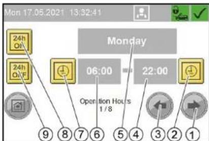
flowchart
graph TD
    A["Delete Fault History"] --> B{Do You Want To Delete Fault History?}
    B --> C["Yes"]
    B --> D{No}
    C --> E["4"]
    D --> F["3"]
    D --> G["2"]
    D --> H["1"]
natural_image
Interior view of a printer or printer unit with visible internal components and a numbered label (1), no readable text or symbols present.① Nyomószivattyú
natural_image
3D printer internal structure showing tubing and components (no text or symbols visible)①Fedél
- Tartsa lenyomva a piros gombot.
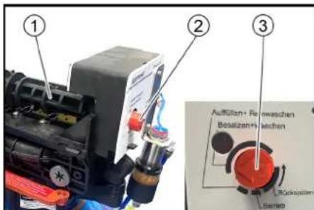
Kijelző hiba példa
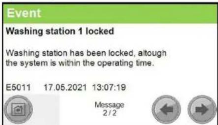
| Hibaszám Ok Elhárítás | ||
| F0003 HP pump 1 connection. No CAN bus data connectionHP pump 1 Inform Service | ||
| F0004 HP pump 1 overload. Output overload HP pump 1 Inform Service | ||
| F0005 Remote control 1 connection. No CAN bus data connection Remote control 1 Inform Service | ||
| F0063 A39 connection. No CAN bus data connection Inform Service | ||
| F0064 A39 overload. Output overload A39 Inform Service | ||
| F0065 A40 connection. No CAN bus data connection Inform Service | ||
| F0066 A40 overload. Output overload A40 Inform Service | ||
| F0101 Exterior temp sensor defective Inform Service | ||
| F0170 | HP pump 1 overcurrent. Current consumption of HP pump 1 too high. | Acknowledge fault. Inform Service if fault occurs again. |
| F0171 HP pump 1 minimum current. Current consumption of HP pump 1 too low Inform Service | ||
| F0172 | Relay / HP pump 1 contactor stuck. HP pump 1 electronics malfunction | Inform Service |
| F0174 | HP pump 1 winding protect.contact | Acknowledge fault. Inform Service if fault occurs again. |
| F0175 HP pump 1 overpressure | Acknowledge fault. Inform Service if fault occurs again. | |
| F0176 | HP pump 1 oil level too low | Refill oil, Acknowledge malfunction |
| F0190 Coin reset remote control 1 | Inform Service | |
| F0191 Coin signal remote control 1 | At mechanical coin acceptor check the micro-switch | |
| F0570 Hot water shortage | Check the hot water supply | |
| F0571 Hot water overtemperature | Acknowledge fault. Inform Service if fault occurs again. | |
| F0572 Hot water temperature sensor defective | Inform Service | |
| F0576 | No flow detected by flow monitor | Acknowledge fault. Inform Service if fault occurs again. |
| F0577 Flow monitor is defective | Acknowledge fault. Inform Service if fault occurs again. | |
| F0578 Automatic hot water circuit-breaker Reset automatic circuit-breaker | ||
| F0610 | BA regeneration failed. Hardness sensor indicateshard water after regeneration. | Refill salt, acknowledge fault |
| F0611 | BA regeneration failed. Regeneration of the bottle could not be started. | Inform Service |
| F0612 Permeate buffer tank dry running. Have the tank filled up to the empty buffer tank level switch (maximum switch-on delay of 15 minutes) | Have the tank filled up to the empty buffer tank level switch (maximum switch-on delay of 15 minutes) | |
| F0613 | Permeate buffer tank level switch. Empty and full buffer tank level switches switch simultaneously | check level switch. |
| F0614 | Permeate buffer tank level switch. Empty and full buffer tank level switches switch simultaneously | check level switch. |
| F0615 Water softening no water pressure | Check the water supply | |
| F0616 | On-site water treatment system | Check on-site water treatment system |
| F1125 | Controller Batterie Back-Up Batterie Of Controller Defective | Inform Service |
H. Jenner
Chairman of the Board of Management
S. Reiser
Director Regulatory Affairs & Certification
Winnenden, 2021/06/01
Spis treści
①Ekran dotykowy
Menu User Administration
①Przycisk menu „System”
Tylko dla serwisu
②Przycisk menu „Language"
③Przycisk menu „Operation Hours Holidays“
④Przycisk menu „Date Time"
Menu Date Time
Menu Operation Hours Holidays
flowchart
graph TD
    A["Delete Fault History"] --> B{Do You Want To Delete Fault History?}
    B --> C["Yes"]
    B --> D{No}
    C --> E["4"]
    D --> F["3"]
    D --> G["2"]
    D --> H["1"]
natural_image
Interior view of a medical or laboratory setup with numbered annotations (1 and 2) showing mechanical components and tubing (no readable text or symbols)natural_image
Interior view of a printer or printer unit with visible internal components and a numbered label (1), no readable text or symbols present.Regulator temperature
natural_image
3D mechanical assembly diagram showing tubing and components inside a machine (no text or symbols visible)①Pokrywa
① Wskaznik kategorii komunikatu:
| Numer usterki | Przyczyna | Sposób usunięcia |
| F0003 HP pump 1 connection. No CAN bus data connectionHP pump 1 Inform Service | ||
| F0004 HP pump 1 overload. Output overload HP pump 1 Inform Service | ||
| F0005 Remote control 1 connection. No CAN bus data connection Remote control 1 Inform Service | ||
| F0063 A39 connection. No CAN bus data connection Inform Service | ||
| F0064 A39 overload. Output overload A39 Inform Service | ||
| F0065 A40 connection. No CAN bus data connection Inform Service | ||
| F0066 A40 overload. Output overload A40 Inform Service | ||
| F0101 Exterior temp sensor defective Inform Service | ||
| F0170 | HP pump 1 overcurrent. Current consumption of HP pump 1 too high. | Acknowledge fault. Inform Service if fault occurs again. |
| F0171 HP pump 1 minimum current. Current consumption of HP pump 1 too low Inform Service | ||
| F0172 Relay / HP pump 1 contactor stuck. HP pump 1 electronics malfunction | Inform Service | |
| F0174 | HP pump 1 winding protect.contact | Acknowledge fault. Inform Service if fault occurs again. |
| F0175 | HP pump 1 overpressure | Acknowledge fault. Inform Service if fault occurs again. |
| F0176 | HP pump 1 oil level too low | Refill oil, Acknowledge malfunction |
| F0190 Coin reset remote control 1 | Inform Service | |
| F0191 | Coin signal remote control 1 | At mechanical coin acceptor check the microswitch |
| F0570 Hot water shortage | Check the hot water supply | |
| F0571 | Hot water overtemperature | Acknowledge fault. Inform Service if fault occurs again. |
| F0572 Hot water temperature sensor defective | Inform Service | |
| F0576 | No flow detected by flow monitor | Acknowledge fault. Inform Service if fault occurs again. |
| F0577 | Flow monitor is defective | Acknowledge fault. Inform Service if fault occurs again. |
| F0578 | Automatic hot water circuit-breaker | Reset automatic circuit-breaker |
| F0610 | BA regeneration failed. Hardness sensor indicateshard water after regeneration. | Refill salt, acknowledge fault |
| F0611 | BA regeneration failed. Regeneration of the bottle could not be started. | Inform Service |
| F0612 Permeate buffer tank dry running. Have the tank filled up to the empty buffer tank level switch (maximum switch-on delay of 15 minutes) | Have the tank filled up to the empty buffer tank level switch (maximum switch-on delay of 15 minutes) | |
| F0613 | Permeate buffer tank level switch. Empty and full buffer tank level switches switch simultaneously | check level switch. |
| F0614 | Permeate buffer tank level switch. Empty and full buffer tank level switches switch simultaneously | check level switch. |
| F0615 | Water softening no water pressure | Check the water supply |
| F0616 On-site water treatment system | Check on-site water | treatment system |
| F1125 | Controller Batterie Back-Up Batterie Of Controller Defective | Inform Service |
2006/42/WE (+2009/127/WE)
2011/65/UE
2009/125/WE
H. Jenner
Chairman of the Board of Management
S. Reiser
Director Regulatory Affairs & Certification
71364 Winnenden (Germany)
Tel.: +49 7195 14-0
① Selector de programe
Post de lucru
① Ecran tactil
② Cutie electrică
① Butonul de meniu „System”
Numai pentru personalul de service
② Butonul de meniu „Language“
③ Butonul de meniu „Operation Hours Holidays“
④Butonul de meniu „Date Time"
Meniu Date Time
Ore de functionare ale componentelor de sistem
flowchart
graph TD
    A["Delete Fault History"] --> B{Do You Want To Delete Fault History?}
    B --> C["Yes"]
    B --> D{No}
    C --> E["4"]
    D --> F["3"]
    D --> G["2"]
    D --> H["1"]
③ Regulator de putere
natural_image
Interior view of a printer or printer unit with visible internal components and a numbered label (1), no readable text or symbols present.① Verificator de monede
natural_image
3D mechanical assembly diagram showing tubing and a blue spherical component inside a chamber (no text or symbols)①Capac
HP pump 1 minimum current
Current consumption of HP pump 1 too low
Inform Service.
F0171 17.05.2021 13:08:38

Message
Exemplu de afişare a defectiunilor
Event
Washing station 1 locked
Washing station has been locked, although
the system is within the operating time.
E5011 17.05.2021 13:07:19

Message
2/2


| Număr de eroare | Cauză | Remedlere | |
| F0003 HP pump 1 connection. No CAN bus data connectionHP pump 1 Inform Service | |||
| F0004 HP pump 1 overload. Output overload HP pump 1 Inform Service | |||
| F0005 Remote control 1 connection. No CAN bus data connection Remote control 1 Inform Service | |||
| F0063 A39 connection. No CAN bus data connection Inform Service | |||
| F0064 A39 overload. Output overload A39 Inform Service | |||
| F0065 A40 connection. No CAN bus data connection Inform Service | |||
| F0066 A40 overload. Output overload A40 Inform Service | |||
| F0101 Exterior temp sensor defective Inform Service | |||
| F0170 | HP pump 1 overcurrent. Current consumption of HP pump 1 too high. | Acknowledge fault. Inform Service if fault occurs again. | |
| F0171 HP pump 1 minimum current. Current consumption of HP pump 1 too low Inform Service | |||
| F0172 | Relay / HP pump 1 contactor stuck. HP pump 1 electronics malfunction | Inform Service | |
| F0174 | HP pump 1 winding protect.contact | Acknowledge fault. Inform Service if fault occurs again. | |
| F0175 HP pump 1 overpressure Acknowledge fault. Inform Service if fault occurs again. | |||
| F0176 | HP pump 1 oil level too low | Refill oil, Acknowledge malfunction | |
| F0190 Coin reset remote control 1 Inform Service | |||
| F0191 Coin signal remote control 1 At mechanical coin acceptor check the microswitch | |||
| F0570 Hot water shortage Check the hot water supply | |||
| F0571 Hot water overtemperature Acknowledge fault. Inform Service if fault occurs again. | |||
| F0572 Hot water temperature sensor defective Inform Service | |||
| F0576 | No flow detected by flow monitor | Acknowledge fault. Inform Service if fault occurs again. | |
| F0577 Flow monitor is defective Acknowledge fault. Inform Service if fault occurs again. | |||
| F0578 Automatic hot water circuit-breaker Reset automatic circuit-breaker | |||
| F0610 | BA regeneration failed. Hardness sensor indicateshard water after regeneration. | Refill salt, acknowledge fault | |
| F0611 | BA regeneration failed. Regeneration of the bottle could not be started. | Inform Service | |
| F0612 Permeate buffer tank dry running. Have the tank filled up to the empty buffer tank level switch (maximum switch-on delay of 15 minutes) | Have the tank filled up to the empty buffer tank level switch (maximum switch-on delay of 15 minutes) | ||
| F0613 | Permeate buffer tank level switch. Empty and full buffer tank level switches switch simultaneously | check level switch. | |
| F0614 | Permeate buffer tank level switch. Empty and full buffer tank level switches switch simultaneously | check level switch. | |
| F0615 Water softening no water pressure Check the water supply | |||
| F0616 On-site water treatment system Check on-site water treatment system | |||
| F1125 | Controller Batterie Back-Up Batterie Of Controller Defective | Inform Service | |
Directive UE relevante
2000/14/UE
2014/30/UE
2006/42/UE (+2009/127/UE)
2011/65/UE
2009/125/UE
Regulament(e) utilizat(e)
(UE) 2019/1781
Norme armonizate aplicate
EN 60335-1
EN 60335-2-79
EN IEC 63000: 2018
EN 55014-1: 2017 + A11: 2020
EN 55014-2: 2015
EN 61000-3-2: 2014
EN 61000-3-3: 2013
EN 62233: 2008
Chairman of the Board of Management
S. Reiser
Director Regulatory Affairs & Certification
71364 Winnenden (Germania)
Tel.: +49 7195 14-0
Fax: +49 7195 14-2212
Winnenden, 2021/06/01
Obsah
Všeobecné upozornenia 217
①Prepínač programov
Pracovisko
①Spínač zariadenia
②Zámok
③Dvierka
-
Otvorte dvierka.
-
Spínač zariadenia nastavte na „1/ON“.
-
Zatvorte dvierka.
Obsluha
Programy umývania
①Prepínač programov umývania
STOP
Program sa preruši.
①Veko
2 Sol'ná nádrž
①Dotyková obrazovka
②Elektrická skrinka
Menu User Administration
④Hot water temperature
Menu Coin value
①Tlačidlo na zmenu nastavenia
Menu Operation Hours Holidays
natural_image
Interior view of a medical or laboratory facility with numbered annotations (1 and 2) showing equipment and tubing (no readable text or symbols)① Predná čast' dýzy
②Filter
③Držiak dýzy
natural_image
Interior view of a printer or printer unit with visible internal components and a numbered label (1), no readable text or symbols present.①Vypúšťacia skrutka oleja
② Olejová nádrž
③ Veko
natural_image
Diagram of a mechanical device with a red arrow indicating direction, labeled with number 1 (no text or symbols on the device itself)①Mincovník
natural_image
3D mechanical assembly diagram showing tubing and components inside a device (no text or symbols visible)①Veko
HP pump 1 minimum current
Current consumption of HP pump 1 too low Inform Service.
F0171 17.05.2021 13:08:38

Message
Washing station 1 locked
Washing station has been locked, although the system is within the operating time.
E5011 17.05.2021 13:07:19

Message 2/2


| Číslo chyby | Príčina | Odstránenie |
| F0003 HP pump 1 connection. No CAN bus data connectionHP pump 1 Inform Service | ||
| F0004 HP pump 1 overload. Output overload HP pump 1 Inform Service | ||
| F0005 Remote control 1 connection. No CAN bus data connection Remote control 1 Inform Service | ||
| F0063 A39 connection. No CAN bus data connection Inform Service | ||
| F0064 A39 overload. Output overload A39 Inform Service | ||
| F0065 A40 connection. No CAN bus data connection Inform Service | ||
| F0066 A40 overload. Output overload A40 Inform Service | ||
| F0101 Exterior temp sensor defective Inform Service | ||
| F0170 | HP pump 1 overcurrent. Current consumption of HP pump 1 too high. | Acknowledge fault. Inform Service if fault occurs again. |
| F0171 HP pump 1 minimum current. Current consumption of HP pump 1 too low Inform Service | ||
| F0172 | Relay / HP pump 1 contactor stuck. HP pump 1 electronics malfunction | Inform Service |
| F0174 | HP pump 1 winding protect.contact | Acknowledge fault. Inform Service if fault occurs again. |
| F0175 HP pump 1 overpressure Acknowledge fault. Inform Service if fault occurs again. | ||
| F0176 | HP pump 1 oil level too low | Refill oil, Acknowledge malfunction |
| F0190 Coin reset remote control 1 Inform Service | ||
| F0191 Coin signal remote control 1 At mechanical coin acceptor check the microswitch | ||
| F0570 Hot water shortage Check the hot water supply | ||
| F0571 Hot water overtemperature Acknowledge fault. Inform Service if fault occurs again. | ||
| F0572 Hot water temperature sensor defective Inform Service | ||
| F0576 | No flow detected by flow monitor | Acknowledge fault. Inform Service if fault occurs again. |
| F0577 Flow monitor is defective Acknowledge fault. Inform Service if fault occurs again. | ||
| F0578 Automatic hot water circuit-breaker Reset automatic circuit-breaker | ||
| F0610 BA regeneration failed. Hardness sensor indicateshard water after regeneration. Refill salt, acknowledge fault | ||
| F0611 | BA regeneration failed. Regeneration of the bottle could not be started. | Inform Service |
| F0612 Permeate buffer tank dry running. Have the tank filled up to the empty buffer tank level switch (maximum switch-on delay of 15 minutes) | Have the tank filled up to the empty buffer tank level switch (maximum switch-on delay of 15 minutes) | |
| F0613 | Permeate buffer tank level switch. Empty and full buffer tank level switches switch simultaneously | check level switch. |
| F0614 | Permeate buffer tank level switch. Empty and full buffer tank level switches switch simultaneously | check level switch. |
| F0615 Water softening no water pressure Check the water supply | ||
| F0616 On-site water treatment system Check on-site water treatment system | ||
| F1125 | Controller Batterie Back-Up Batterie Of Controller Defective | Inform Service |
Poruchy bez zobrazenia
Poruchy na vysokotlakovom čerpadle
2006/42/ES (+2009/127/ES)
2011/65/EU
2009/125/ES
H. Jenner
Chairman of the Board of Management
S. Reiser
Director Regulatory Affairs & Certification
71364 Winnenden (Germany)
Tel.: +49 7195 14-0
Fax: +49 7195 14-2212
Winnenden, 01.06.2021
Sisukord
Üldised juhised.... 232
① Seadmelüliti
②Lukk
③Uks
4. Avage uks.
5. Keerake seadmelüliti „1/ON“ peale.
6. Sulgege uks.
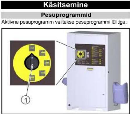
①Kaas
② Soolapaak
①Puuteekraan
②Elektrikast
flowchart
graph TD
    A["Delete Fault History"] --> B{Do You Want To Delete Fault History?}
    B --> C["Yes"]
    B --> D{No}
    C --> E["4"]
    D --> F["3"]
    D --> G["2"]
    D --> H["1"]
① Düüsi esiosa
②Filter
③Düüsi hoidik
- Eemaldage ja puhastage filter.
- Sisestage filter.
- Keerake düüsi esiosa düüsihoidiku külge ja pingutage kinni.
natural_image
Interior view of a printer or printer assembly showing internal components and a numbered label (1), with no visible text or symbols.Käigustvõtmine
- Keerake seadmelüliti "0/OFF" peale.
natural_image
3D mechanical assembly diagram showing tubing and components inside a machine (no text or symbols visible)①Kaas
Näide rikke näit
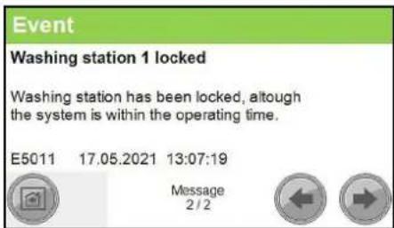
Näide sündmuse näit
| Vea number Põhjus Kõrvaldamine | ||
| F0003 HP pump 1 connection. No CAN bus data connectionHP pump 1 Inform Service | ||
| F0004 HP pump 1 overload. Output overload HP pump 1 Inform Service | ||
| F0005 Remote control 1 connection. No CAN bus data connection Remote control 1 Inform Service | ||
| F0063 A39 connection. No CAN bus data connection Inform Service | ||
| F0064 A39 overload. Output overload A39 Inform Service | ||
| F0065 A40 connection. No CAN bus data connection Inform Service | ||
| F0066 A40 overload. Output overload A40 Inform Service | ||
| F0101 Exterior temp sensor defective Inform Service | ||
| F0170 | HP pump 1 overcurrent. Current consumption of HP pump 1 too high. | Acknowledge fault. Inform Service if fault occurs again. |
| F0171 HP pump 1 minimum current. Current consumption of HP pump 1 too low Inform Service | ||
| F0172 Relay / HP pump 1 contactor stuck. HP pump 1 electronics malfunction Inform Service | ||
| F0174 | HP pump 1 winding protect.contact | Acknowledge fault. Inform Service if fault occurs again. |
| F0175 | HP pump 1 overpressure | Acknowledge fault. Inform Service if fault occurs again. |
| F0176 | HP pump 1 oil level too low | Refill oil, Acknowledge malfunction |
| F0190 Coin reset remote control 1 | Inform Service | |
| F0191 | Coin signal remote control 1 | At mechanical coin acceptor check the microswitch |
| F0570 Hot water shortage | Check the hot water supply | |
| F0571 | Hot water overtemperature | Acknowledge fault. Inform Service if fault occurs again. |
| F0572 Hot water temperature sensor defective | Inform Service | |
| F0576 | No flow detected by flow monitor | Acknowledge fault. Inform Service if fault occurs again. |
| F0577 | Flow monitor is defective | Acknowledge fault. Inform Service if fault occurs again. |
| F0578 | Automatic hot water circuit-breaker | Reset automatic circuit-breaker |
| F0610 | BA regeneration failed. Hardness sensor indicateshard water after regeneration. | Refill salt, acknowledge fault |
| F0611 | BA regeneration failed. Regeneration of the bottle could not be started. | Inform Service |
| F0612 Permeate buffer tank dry running. Have the tank filled up to the empty buffer tank level switch (maximum switch-on delay of 15 minutes) | Have the tank filled up to the empty buffer tank level switch (maximum switch-on delay of 15 minutes) | |
| F0613 | Permeate buffer tank level switch. Empty and full buffer tank level switches switch simultaneously | check level switch. |
| F0614 | Permeate buffer tank level switch. Empty and full buffer tank level switches switch simultaneously | check level switch. |
| F0615 Water softening no water pressure | Check the water supply | |
| F0616 On-site water treatment system | Check on-site water | treatment system |
| F1125 | Controller Batterie Back-Up Batterie Of Controller Defective | Inform Service |
Rikked ilma näiduta
Rikked körgsurvepumbal
Toode: Körgsurvepesur
Tüüp: 1.319-xxx
2006/42/EÜ (+2009/127/EÜ)
2011/65/EL
2009/125/EÜ
Chairman of the Board of Management
S. Reiser
Director Regulatory Affairs & Certification
71364 Winnenden (Germany)
Tel: +49 7195 14-0
Winnenden, 2021/06/01
Saturs
① lerīces slēdzis
② Slëdzene
③ Durvis
4. Atver durvis.
5. Ierīces slēdzi pagriezt uz "1/ON" (iesl.).
6. Aizveriet durvis.
Apkalpošana
①Vāks
② Sāls tvertne
flowchart
graph TD
    A["Delete Fault History"] --> B{Do You Want To Delete Fault History?}
    B --> C["Yes"]
    B --> D{No}
    C --> E["④"]
    D --> F["③"]
    D --> G["②"]
    D --> H["①"]
②Termostata regulators
③ Jaudas regulators
- Iestatiet termostata regulatoru atkaribā no āra temperalūras:
natural_image
Interior view of a medical or laboratory setup with numbered annotations (1 and 2) pointing to internal components (no readable text or symbols)natural_image
Interior view of a printer or printer unit with visible internal components and a numbered label (1), no readable text or symbols present.① Monētu skaitītājs
natural_image
3D mechanical assembly diagram showing tubing and components inside a device (no text or symbols visible)①Vāks
- Nospiediet un turiet sarkano pogu.
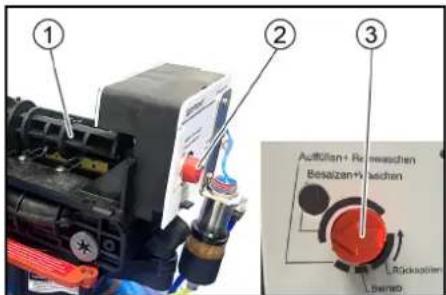
| Klūdas numurs | Cēlonis | Novērsana |
| F0003 HP pump 1 connection. No CAN bus data connectionHP pump 1 Inform Service | ||
| F0004 HP pump 1 overload. Output overload HP pump 1 Inform Service | ||
| F0005 Remote control 1 connection. No CAN bus data connection Remote control 1 Inform Service | ||
| F0063 A39 connection. No CAN bus data connection Inform Service | ||
| F0064 A39 overload. Output overload A39 Inform Service | ||
| F0065 A40 connection. No CAN bus data connection Inform Service | ||
| F0066 A40 overload. Output overload A40 Inform Service | ||
| F0101 Exterior temp sensor defective Inform Service | ||
| F0170 | HP pump 1 overcurrent. Current consumption of HP pump 1 too high. | Acknowledge fault. Inform Service if fault occurs again. |
| F0171 HP pump 1 minimum current. Current consumption of HP pump 1 too low Inform Service | ||
| F0172 | Relay / HP pump 1 contactor stuck. HP pump 1 electronics malfunction | Inform Service |
| F0174 | HP pump 1 winding protect.contact | Acknowledge fault. Inform Service if fault occurs again. |
| F0175 HP pump 1 overpressure Acknowledge fault. Inform Service if fault occurs again. | ||
| F0176 | HP pump 1 oil level too low | Refill oil, Acknowledge malfunction |
| F0190 Coin reset remote control 1 Inform Service | ||
| F0191 Coin signal remote control 1 At mechanical coin acceptor check the microswitch | ||
| F0570 Hot water shortage Check the hot water supply | ||
| F0571 Hot water overtemperature Acknowledge fault. Inform Service if fault occurs again. | ||
| F0572 Hot water temperature sensor defective Inform Service | ||
| F0576 | No flow detected by flow monitor | Acknowledge fault. Inform Service if fault occurs again. |
| F0577 Flow monitor is defective Acknowledge fault. Inform Service if fault occurs again. | ||
| F0578 Automatic hot water circuit-breaker Reset automatic circuit-breaker | ||
| F0610 | BA regeneration failed. Hardness sensor indicateshard water after regeneration. | Refill salt, acknowledge fault |
| F0611 | BA regeneration failed. Regeneration of the bottle could not be started. | Inform Service |
| F0612 Permeate buffer tank dry running. Have the tank filled up to the empty buffer tank level switch (maximum switch-on delay of 15 minutes) | Have the tank filled up to the empty buffer tank level switch (maximum switch-on delay of 15 minutes) | |
| F0613 | Permeate buffer tank level switch. Empty and full buffer tank level switches switch simultaneously | check level switch. |
| F0614 | Permeate buffer tank level switch. Empty and full buffer tank level switches switch simultaneously | check level switch. |
| F0615 Water softening no water pressure Check the water supply | ||
| F0616 On-site water treatment system Check on-site water treatment system | ||
| F1125 | Controller Batterie Back-Up Batterie Of Controller Defective | Inform Service |
H. Jenner
Chairman of the Board of Management
S. Reisen
Director Regulatory Affairs & Certification
① Programos atrankusis jungiklis
Darbo vieta
①renginio jungiklis
② Sklastis
③Durelès
4. Atidarykite dureles.
5. Irenginio jungiklj pasukite j 1/|J. padëtj.
6. Uždarykite dureles.
Valdymas
Plovimo programos
Aktyvioji plovimo programa pasirenkama plovimo programos jungikliu.
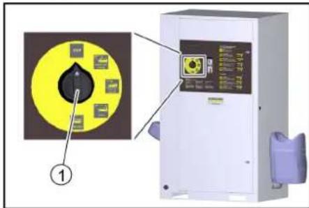
①Plovimo programos jungiklis
STOP
Programos vykdymas nutraukiamas.
① Programos atrankusis jungiklis
①Jutiklinis ekranas
② Skirstomasis skydelis
flowchart
graph TD
    A["0,36 / 65 Sek"] --> B["High-Pressure Wash 90s / 0,50"]
    B --> C["Enabling a washing station"]
    B --> D["Heating remote control"]
    C --> E["Washing"]
    D --> E
    E --> F["⑤"]
    E --> G["④"]
    E --> H["③"]
    E --> I["②"]
    E --> J["①"]
① Kito lango mygtukas
②Plovimo programos keitimo mygtukas
① Mygtukas „Užblokuoti plovimo vietą“
② Mygtukas „Panaikinti blokavimą“
natural_image
Interior view of a mechanical device with labeled component (1), showing internal components and wiring (no readable text or symbols)①Monetų tikrintuvas
natural_image
Mechanical assembly diagram showing a blue cylinder connected to tubing and a black base, with no visible text or symbols.①Dangtelis
Sutrikimo rodmens pavyzdys
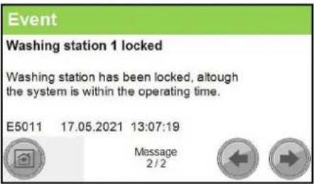
| Klaidos numeris Priežastis Šalinimas | |||
| F0003 HP pump 1 connection. No CAN bus data connectionHP pump 1 Inform Service | |||
| F0004 HP pump 1 overload. Output overload HP pump 1 Inform Service | |||
| F0005 Remote control 1 connection. No CAN bus data connection Remote control 1 Inform Service | |||
| F0063 A39 connection. No CAN bus data connection Inform Service | |||
| F0064 A39 overload. Output overload A39 Inform Service | |||
| F0065 A40 connection. No CAN bus data connection Inform Service | |||
| F0066 A40 overload. Output overload A40 Inform Service | |||
| F0101 Exterior temp sensor defective Inform Service | |||
| F0170 | HP pump 1 overcurrent. Current consumption of HP pump 1 too high. | Acknowledge fault. Inform Service if fault occurs again. | |
| F0171 HP pump 1 minimum current. Current consumption of HP pump 1 too low Inform Service | |||
| F0172 | Relay / HP pump 1 contactor stuck. HP pump 1 electronics malfunction | Inform Service | |
| F0174 | HP pump 1 winding protect.contact | Acknowledge fault. Inform Service if fault occurs again. | |
| F0175 HP pump 1 overpressure Acknowledge fault. Inform Service if fault occurs again. | |||
| F0176 | HP pump 1 oil level too low | Refill oil, Acknowledge malfunction | |
| F0190 Coin reset remote control 1 Inform Service | |||
| F0191 Coin signal remote control 1 At mechanical coin acceptor check the micro-switch | |||
| F0570 Hot water shortage Check the hot water supply | |||
| F0571 Hot water overtemperature Acknowledge fault. Inform Service if fault occurs again. | |||
| F0572 Hot water temperature sensor defective Inform Service | |||
| F0576 | No flow detected by flow monitor | Acknowledge fault. Inform Service if fault occurs again. | |
| F0577 Flow monitor is defective Acknowledge fault. Inform Service if fault occurs again. | |||
| F0578 Automatic hot water circuit-breaker Reset automatic circuit-breaker | |||
| F0610 | BA regeneration failed. Hardness sensor indicateshard water after regeneration. | Refill salt, acknowledge fault | |
| F0611 | BA regeneration failed. Regeneration of the bottle could not be started. | Inform Service | |
| F0612 Permeate buffer tank dry running. Have the tank filled up to the empty buffer tank level switch (maximum switch-on delay of 15 minutes) | Have the tank filled up to the empty buffer tank level switch (maximum switch-on delay of 15 minutes) | ||
| F0613 | Permeate buffer tank level switch. Empty and full buffer tank level switches switch simultaneously | check level switch. | |
| F0614 | Permeate buffer tank level switch. Empty and full buffer tank level switches switch simultaneously | check level switch. | |
| F0615 Water softening no water pressure Check the water supply | |||
| F0616 On-site water treatment system Check on-site water treatment system | |||
| F1125 | Controller Balterie Back-Up Batterie Of Controller Defective | Inform Service | |
H. Jenner
Chairman of the Board of Management
S. Reiser
Director Regulatory Affairs & Certification
①Перемикач програм
Робоче місце
①Кришка
② Бак для солі
natural_image
Interior view of a printer or printer unit with visible internal components and a numbered label (1), no readable text or symbols present.natural_image
3D mechanical assembly diagram showing tubing and a blue spherical component (no text or symbols visible)①Кришка
| Номер помилки | Причина | Усунення | |
| F0003 HP pump 1 connection. No CAN bus data connectionHP pump 1 Inform Service | |||
| F0004 HP pump 1 overload. Output overload HP pump 1 Inform Service | |||
| F0005 Remote control 1 connection. No CAN bus data connection Remote control 1 Inform Service | |||
| F0063 A39 connection. No CAN bus data connection Inform Service | |||
| F0064 A39 overload. Output overload A39 Inform Service | |||
| F0065 A40 connection. No CAN bus data connection Inform Service | |||
| F0066 A40 overload. Output overload A40 Inform Service | |||
| F0101 Exterior temp sensor defective Inform Service | |||
| F0170 | HP pump 1 overcurrent. Current consumption of HP pump 1 too high. | Acknowledge fault. Inform Service if fault occurs again. | |
| F0171 HP pump 1 minimum current. Current consumption of HP pump 1 too low Inform Service | |||
| F0172 | Relay / HP pump 1 contactor stuck. HP pump 1 electronics malfunction | Inform Service | |
| F0174 | HP pump 1 winding protectcontact | Acknowledge fault. Inform Service if fault occurs again. | |
| F0175 HP pump 1 overpressure Acknowledge fault. Inform Service if fault occurs again. | |||
| F0176 | HP pump 1 oil level too low | Refill oil, Acknowledge malfunction | |
| F0190 Coin reset remote control 1 Inform Service | |||
| F0191 Coin signal remote control 1 At mechanical coin acceptor check the microswitch | |||
| F0570 Hot water shortage Check the hot water supply | |||
| F0571 Hot water overtemperature Acknowledge fault. Inform Service if fault occurs again. | |||
| F0572 Hot water temperature sensor defective Inform Service | |||
| F0576 | No flow detected by flow monitor | Acknowledge fault. Inform Service if fault occurs again. | |
| F0577 Flow monitor is defective Acknowledge fault. Inform Service if fault occurs again. | |||
| F0578 Automatic hot water circuit-breaker Reset automatic circuit-breaker | |||
| F0610 | BA regeneration failed. Hardness sensor indicateshard water after regeneration. | Refill salt, acknowledge fault | |
| F0611 | BA regeneration failed. Regeneration of the bottle could not be started. | Inform Service | |
| F0612 Permeate buffer tank dry running. Have the tank filled up to the empty buffer tank level switch (maximum switch-on delay of 15 minutes) | Have the tank filled up to the empty buffer tank level switch (maximum switch-on delay of 15 minutes) | ||
| F0613 | Permeate buffer tank level switch. Empty and full buffer tank level switches switch simultaneously | check level switch. | |
| F0614 | Permeate buffer tank level switch. Empty and full buffer tank level switches switch simultaneously | check level switch. | |
| F0615 Water softening no water pressure Check the water supply | |||
| F0616 On-site water treatment system Check on-site water treatment system | |||
| F1125 | Controller Batterie Back-Up Batterie Of Controller Defective | Inform Service | |
S. Reiser
Director Regulatory Affairs & Certification
71364 Winnenden (Germany)
Тел.: +49 7195 14-0
Факс: +49 7195 14-2212
natural_image
Black silhouette of a hand giving a thumbs-up gesture (no text or symbols)THANK YOU!
MERCI! DANKE! iGRACIAS!

Register your product and benefit from many advantages.
www.kaercher.com/welcome


Rate your product and tell us your opinion.
natural_image
Icon showing a gear and wrench inside a square frame (no text or symbols)www.kaercher.com/dealersearch
Alfred Kärcher SE & Co. KG
Alfred-Kärcher-Str. 28-40
71364 Winnenden (Germany)
Tel.: +49 7195 14-0
Fax: +49 7195 14-2212


- Inhalt
- Contents
- General notes
- Technical terms
- Environmental protection
- Supplementary environmental protection instructions
- Safety instructions
- Regulations and guidelines
- Hazard levels
- ⚠️DANGER
- ⚠ WARNING
- △CAUTION
- ATTENTION
- Symbols on the system
- Hearing protection
- Switching off in the event of an emergency
- Workstation
- Intended use
- Initial startup
- Operation
- Washing programmes
- STOP
- Power foam (only with 3-tool version)
- High-pressure wash
- Foam wash
- Rinse
- Hot wax
- Insects Loosening (option)
- Dirt Loosening (option)
- Top care (option)
- Operating sequence
- Note
- Single tool version
- Dual tool version
- 3-tool version
- Washing time
- Providing the detergent
- △DANGER
- Vent the dosing pump
- Replenishing softening salt (only with base exchanger option)
- Settings at base exchanger BA 42 and BA 65
- Setting the regeneration cycle
- Setting brine dosage
- Controller
- Operating state symbols
- User symbols
- Changing the setting
- Menu overview
- Menu Washing
- Menu Service
- Menu Settings
- Menu User Administration
- Changing code
- Menu Wash-Program Settings
- Changing the parameters of a washing program
- Menu Machine
- Menu Components
- Menu Coin value
- Menu Lock
- Menu General
- Menu Date Time
- Setting the time
- Menu Operation Hours Holidays
- Menu Language
- Menu General Info
- Menu Turnover
- Menu Operating Hours
- Menu Maintenance Diagnostic
- Menu Interval
- Menu System Information
- Menu Fault History
- Menu Event History
- Frost protection (option)
- △WARNING
- Prerequisites for frost protection
- Hot air blower
- Anti-freezing circulation circuit
- Frost protection with lost water
- Maintenance work before and after the frost period
- Power foamClean the nozzle
- Disconnection from system (option)
- Shutting down
- Shutdown in the case of potential frost
- Additionally for the WSO attachment kit
- Description of the unit
- Flow chart
- Monitoring and safety devices
- Pressure relief valve
- Motor circuit breaker
- Winding protection contact
- Temperature controller
- Overheating protection
- Dry running sensor
- Hard water sensor
- Pressure sensor
- Buffer tank full level switch
- Care and service
- Maintenance instructions
- Safety inspection/maintenance contract
- Oil change
- Danger of burns
- Cleaning the sieve
- Cleaning the coin slot
- Manual regeneration WSO (BA 65/RO 75)
- Troubleshooting guide
- Risk of fatal injury from electric shock.
- A high-pressure water jet can escape from damaged parts and cause injuries.
- Who is permitted to eliminate faults?
- Currently applicable errors, faults and events
- Message displays
- Warranty
- Transport
- Risk of injury, risk of damage
- Storage
- Risk of injury and damage
- Accessories and spare parts
- Declaration of Conformity
- EU Declaration of Conformity
- Currently applicable EU Directives
- Commission Regulation(s)
- Harmonised standards used
- Applied conformity evaluation method
- Sound power level dB(A)
- Declaration of Conformity (UK)
- Currently applicable UK Regulations
- Designated standards used
- Applied conformity assessment procedure
- Contenu
- Menù User Administration
- Menù Operation Hours Holidays
- Inhoud
- Werkplek
- Bediening
- Wasprogramma's
- ① Deksel
- Puesto de trabajo
- Indice
- Local de trabalho
- HP pump 1 minimum current
- Washing station 1 locked
- Arbeidsplass
- Betjening
- Vaskeprogrammer
- Merknad
- Meny User Administration
- Endre parametere for et vaskeprogram
- Meny Coin value
- Meny Operation Hours Holidays
- Meny Holiday fix
- Ta ut av drift
- Rengjør silen
- Lydeffektnivå dB(A)
- Innehåll
- Arbetsplats
- Meny Components
- Meny Operation Hours
- Meny Interval
- Meny Event History
- Event
- Sisältö
- Valikko User Administration
- Valikko Components
- Valikko Date Time
- Valikko Operation Hours Holidays
- Valikko Maintenance Diagnostic
- Valikko Interval
- Valikko Fault History
- Valikko Event History
- Menü User Administration
- Menü Operation Hours Holidays
- Menü Operation Hours
- Spis treści
- Regulator temperature
- Post de lucru
- Meniu Date Time
- Directive UE relevante
- Regulament(e) utilizat(e)
- Norme armonizate aplicate
- Obsah
- Pracovisko
- Obsluha
- Programy umývania
- Sisukord
- Käigustvõtmine
- Saturs
- Apkalpošana
- Darbo vieta
- Valdymas
- Plovimo programos
- Робоче місце
- THANK YOU!
- MERCI! DANKE! iGRACIAS!
Brand : Kärcher
Model : SB OB
Category : Automatic boot washer