HDS 1320 De Tr1 - Pressure washer Kärcher - Free user manual and instructions
Find the device manual for free HDS 1320 De Tr1 Kärcher in PDF.
User questions about HDS 1320 De Tr1 Kärcher
0 question about this device. Answer the ones you know or ask your own.
Ask a new question about this device
Download the instructions for your Pressure washer in PDF format for free! Find your manual HDS 1320 De Tr1 - Kärcher and take your electronic device back in hand. On this page are published all the documents necessary for the use of your device. HDS 1320 De Tr1 by Kärcher.
USER MANUAL HDS 1320 De Tr1 Kärcher
natural_image
Technical line drawing of a portable airship or vehicle with attached mechanical components (no text or symbols)Deutsch 2
English 16
Français 31
Italiano 45
Español 59
Português 74
Nederlands 89
Türkçe 103
Svenska 117
Suomi 131
Norsk 145
Dansk 159
Eesti 173
Latviešu 187
Lietuviškai 201
Polski 215
Magyar 229
Čeština 243
Slovenčina 257
Slovenščina 271
Română 285
Hrvatski 300
Srpski 314
Ελληνικά 328
Русский 343
Українська 359
Български 374
Қазақша 389
العربية 404
Inhalt
text_image
Technical diagram of a truck's internal components with numbered labels pointing to various partstext_image
Labeled diagram of a mechanical or electrical component with numbered parts and control buttonstext_image
ESM3710-N SET P ✓ SEMKO 8.8:8.8natural_image
Pure technical line drawing of a mechanical or electrical component without any text, numbers, or symbolsnatural_image
Pure technical line drawing of industrial piping and valves without any text or symbolsnatural_image
Technical line drawing of a mechanical assembly with no visible text or symbolsnatural_image
Technical line drawing of a mechanical device with an arrow indicating direction (no text or symbols)natural_image
Technical line drawing of a mechanical assembly with no visible text or symbolstext_image
Technical diagram of a mechanical engine with numbered components labeled 1, 2, and 3natural_image
Technical line drawing of a mechanical assembly with no visible text or symbols①Schmiernippel
natural_image
Technical line drawing of a mechanical assembly with two directional arrows indicating movement or force directions (no text or symbols present)HD 9/23 GeTr1 + HD 9/23 DeTr1
Gemessen: 105
Garantiert: 107
HDS 13/20 DeTr1
Gemessen: 97
Garantiert: 100
HDS 13/35 DeTr1 + HDS 9/50 DeTr1
Gemessen: 100
Garantiert: 102
HDS 17/20 DeTr1
Gemessen: 100
Garantiert: 102
OPTIONAL

H. Jenner
Chairman of the Board of Management

S. Reiser
Manager Regulatory Affairs & Certification
71364 Winnenden (Germany)
Tel.: +49 7195 14-0
Fax: +49 7195 14-2212
Winnenden, 2023/01/01
Technische Daten
HDS 9/50 DE Tr1 HDS 13/35 DE Tr1 HDS 13/20 DE Tr1 HDS 17/20 DE Tr1
Environmental protection 16
Symbols on the device.... 16
Intended use 16
Safety instructions.... 16
Function 16
Safety devices.... 16
Device overview.... 17
Initial startup.... 19
Operation 20
Transport....22
Storage 22
Care and service.... 23
Troubleshooting guide 26
Warranty 28
Accessories and spare parts.... 28
Declaration of Conformity 29
Technical data.... 30
General notes

Read these original operating instructions before using your device for the first time, follow them accordingly and
keep them for later use or for future owners.
- Notify the dealer immediately in the case of shipping damage.
- Check package content when unpacking.
- Be sure to read the safety instructions no. 5.951-949.0 prior to the initial startup!
Environmental protection

The packing materials can be recycled. Please dispose of packaging in accordance with the environmental regulations.

Electrical and electronic devices contain valuable, recyclable materials and often components such as batteries, rechargeable batteries or oil,
which - if handled or disposed of incorrectly - can pose a potential danger to human health and the environment. However, these components are required for the correct operation of the device. Devices marked by this symbol are not allowed to be disposed of together with the household rubbish.
Notes on the content materials (REACH)
Current information on content materials can be found at: www.kaercher.de/REACH
Supplementary environmental protection instructions
Please do not allow engine oil, heating oil, diesel and petrol to enter the environment. Please protect the ground and dispose of old oil in an environmentally friendly manner.
Symbols on the device

Do not point the high-pressure jet at people, animals, live electrical equipment or at the device itself.
Protect the device from frost.

Danger of injury from electrical voltage. Only qualified electricians or authorised and qualified technical specialists are permitted to work on the electrical systems.

Warning of risk of crushing!

Risk of eye and hearing damage. Wear eye and hearing protection.

Health risk from poisonous exhaust gases. Never inhale the exhaust gases.

Risk of burns from hot surfaces.
Intended use
Note
Only applies to Germany: The device is only intended for mobile (not stationary) operation.
- The device is used especially at locations where there is no electrical connection and it is necessary to work with hot water.
- Cleaning of: Machines, Vehicles, Structures, Tools, Facades, Terraces, Gardening tools, etc.
△DANGER
Risk of injury!
When using at petrol stations or other hazardous areas Please adhere to the respective safety instructions.
Please do not let mineral oil contaminated waste water reach soil, water or the sewage system. Therefore, perform motor wash and undercarriage wash only on specified places with an oil separator
Water supply limit values
ATTENTION
Dirty water
Premature wear and tear or deposits in the device Supply the device using only clean water, or recycled water that does not exceed the specified limit values. The following limit values apply to the water supply:
| ph-value 6,5-9,5 | |
| electrical conductivity Conductivity of fresh water +1200 μS/cm | |
| settleable solids ** < 0,5 mg/l | |
| total suspended solids *** < 50 mg/l | |
| Hydrocarbons < 20 mg/l | |
| Chloride | < 300 mg/l |
| Sulphate | < 240 mg/l |
| Calcium | < 200 mg/l |
| Total hardness | < 28 °dH< 50 °TH< 500 ppm (mg CaCO3/l) |
| Iron | < 0,5 mg/l |
| Manganese | < 0,05 mg/l |
| Copper | < 2 mg/l |
| Active chloride | < 0,3 mg/l |
Free of unpleasant odours
* Maximum total of 2000 μS/cm** Sample volume 1 l, settling time 30 min*** No abrasive substances
Safety instructions
DANGER
- Never operate the device in confined spaces.
- Do not store, spill or use diesel fuel near open flames or appliances such as stoves, heating boilers, water heaters, etc., that have pilot lights or can produce sparks.
• Never overfill the fuel tank.
General
- Observe the respectively applicable national regulations for liquid jet cleaners.
- Observe the respectively applicable accident prevention regulations. Liquid jet cleaners must be tested regularly and the results of the test recorded in writing.
- The heating system of the device is a combustion system and must be checked regularly in accordance with the relevant national legal regulations.
- Only applies to devices with vapour mode attachment kit: According to the applicable national regulations, this high-pressure cleaner must be initially commissioned by a qualified person when used commercially. KÄRCHER has already performed and documented this initial commissioning for you. You can request the documentation for this from your KÄRCHER partner. Please have the part and plant number of the device available when enquiring about the documentation.
- Only applies to devices with vapour mode attachment kit: We explicitly state that the application national regulations require that this device must be inspected regularly by a qualified person. Please contact your KÄRCHER partner for this.
- No changes may be made to the device or accessories.
Tires
△DANGER
Danger of accident
Tyres can come loose at high speed. On vehicles authorised for 100km / h : Tyres must not be older than six years. In the event of damage, dents/ cracks on the side wall, tread separation etc., the tyres must be replaced immediately.
High-pressure hose
△DANGER
Risk of injury!
- Use only original high-pressure hoses.
- The high-pressure hose and the spray unit must be suitable for use at the maximum operating pressure specified in the technical data.
-
Avoid contact with chemicals.
-
Check the high-pressure hose daily. Do not continue using kinked hoses. Do not continue using the high-pressure hose if the outer wire mesh layer is visible.
- Do not continue using the high-pressure hose with a damaged thread.
- Lay the high-pressure hose in such a way that it cannot be driven over.
- A hose that has been driven over, kinked or subjected to impacts may no longer be used, even if no damage is visible.
- Store the high-pressure hose in such a way that it is not subjected to any mechanical loads.
Function
- The high pressure pump is driven by an intermediate transmission by a diesel engine.
- Between the float container and the high-pressure pump, the water is heated via a heat exchanger located in the motor's cooling circuit.
- When the jet operation is interrupted, the overflow valve switches to pressure-free water circulation and the motor continues running at idle speed.
- The water is heated by a pressure-side burner with oil firing.
- During hot water operation, softening agents are added to the water.
- HDS 9/50, HDS 13/35 only (optional with HDS 13/20, HDS 17/20): The operating pressure can be selected via the speed control of the motor.
- HDS 13/20, HDS 17/20 only: The high-pressure pump draws detergent. The proportion of detergent in the water can be adjusted using a dosing valve.
- HDS 13/20, HDS 17/20 only (option): Attachment kit for removing weeds with hot water.
- HDS 13/20, HDS 17/20 only (option): Attachment kit for cleaning and disinfection with steam.
Safety devices
Safety devices protect the user and may not be disabled or functionally circumvented.
Emergency stop switch
- For immediate shut down of all functions: Press the Emergency Stop switch.
Safety button of front cover
- The device can only be put into operation if the front cover is closed.
- If the front cover is opened during operation, the device shuts down and the indicator light front cover/emergency stop is red.
Overflow valve
- If the trigger gun is closed, the overflow valve opens and the high-pressure pump leads the water back into the float container. This prevents the maximum permissible working pressure from being exceeded
- HDS 13/20, HDS 17/20 only: When the water quantity is reduced via the pressure/quantity control on the trigger gun, the overflow valve opens and part of the water flows into the float container or the water reservoirs (depending on the position of the ball tap return flow valve).
- The overflow valve is set and sealed at the factory. Setting must only be performed by Customer Service.
Safety valve
- The safety valve opens if the overflow valve or pressure switch is faulty.
- The safety valve is adjusted and sealed at the factory. The adjustment is performed only by customer service.
Charging current monitoring of battery
- If the charging current of the alternator is insufficient during the charging process of the battery, the device shuts down.
• Display malfunction: ERROR 1
Temperature monitoring of water inlet or cooling water
- If the water inlet temperature exceeds the maximum permissible temperature, the device shuts down.
- If the cooling water temperature exceeds the maximum admissible temperature, the device shuts down.
• Display malfunction: ERROR 3
Water shortage safeguard of float container
- The water shortage safeguard prevents the motor from being switched on in case of a water shortage.
• Display malfunction: ERROR 4
Water shortage safeguard of burner
- The water shortage safeguard (flow switch) prevents the burner from overheating in the case of a shortage of water. The burner operates only when there is adequate water supply.
• Display malfunction: ERROR 5
Pressure switch/flow switch
- The combination pressure switch/flow switch shuts down the device in case of water shortage or leakage.
• Display malfunction: ERROR 5
Fill level monitoring of fuel
- The device shuts down in the event of a fuel shortage (fuel tank empty).
Note
The device can be operated for another 5 minutes until the fuel tank is completely empty by switching the device off and then on again.
- The device shuts down if the fuel sensor is defective.
• Display malfunction: ERROR 6 - The pressure switch turns off the motor when the minimum engine oil pressure is not maintained.
• Display malfunction: ERROR 7
Engine oil pressure
Exhaust gas thermostat
- The exhaust gas thermostat switches off the burner when the exhaust gas temperature is too high.
• Display malfunction: ERROR 9
Temperature monitoring of burner
- If the water temperature at the burner outlet exceeds the maximum admissible temperature, the device switches off the burner.
- The device switches off the burner if the temperature sensor is defective.
• Display malfunction: ERROR 10
Flame monitoring
- The flame monitoring switches off the burner in case of a burner fault.
• Display malfunction: ERROR 11 or 12
Switch off after expiry of standby time or after continuous operation
- If the standby time or the continuous operation time of 45 minutes is exceeded, the electronics switch the device off (factory setting).
• Display malfunction: ERROR 14 or 15
Safety latch
The safety latch on the trigger gun prevents the device from being switched on unintentionally.
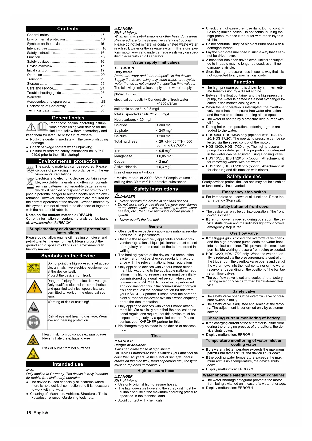
Device overview
Description of the device
text_image
Technical diagram of a truck's internal components with numbered labels pointing to various parts①Reflector (on both sides)
②Rear cover
③Combined brake/tail light with direction indicator (left)
④ Hose inlet with closed rear cover
⑤Lock of rear cover
⑥ Licence plate with licence plate lights
⑦Combined brake/tail light with direction indicator (right)
⑧ Recessed grip of the front cover (on both sides)
⑨ Marker light (on both sides)
⑩Chock
⑪ Support wheel
12 Hooks
⑬ Vehicle lighting plug connection
⑭ Safety rope
⑮ Tow bar
⑯ Parking brake
⑰ Coupling lever
⑱Holder for vehicle lighting plug connection
⑲Supporting wheel crank
⑳Lock of front cover
②1Front cover
②Exhaust opening
②3Lifting eyelet

① Diesel engine
② Intermediate transmission
③ High-pressure pump
④ Safety block of burner
⑤ Exhaust pipe
⑥ Equalising reservoir of motor coolant
⑦ Maintenance opening of water tank (left)
⑧ Air filter
⑨Type plate
10Battery
⑪ Vehicle identification number
⑫Burner blower
⑬ Fuel pump
14 Booster heater
⑮Ignition transformer
⑯ Maintenance opening of water reservoir (right)
⑰ Detergent container
⑱ Filter at the detergent suction hose
⑲Detergent suction hose with level sensor
20 Detergent dosing valve
②1 Storage compartment for trigger gun
22 Storage compartment for spray lance
23 High-pressure hose
24 High pressure hose reel
25 Emergency stop switch
26 Low-pressure hose reel
27 Liquid softener container
28 Antifreeze container
⑲Filling nozzle of fuel tank with sieve
30Frost protection ball tap
③1 Filling level indicator of water reservoirs
③2Float container
③3Speed control
③4 Filling hole of float container with cover/wing screw
③5 Filling hole for liquid softner
③6 Ball tap of return switchover
37 Switch box
③8 Cover plate (right)
⑲Cover plate (left)
④0 Supply tap of water reservoirs
④1Drain tap
④2Frost protection hose
④3 Water hose
④4 Water inlet filter
45 Pressure gauge
④6 Supply frost protection or parking position for GEKA low-pressure connection
④7 Return flow frost protection or parking position for high-pressure connection
48Tank cap
49 Control panel
Control panel

text_image
1 2 3 4 5 6 7 8 9 V2.0 V3.00/OFF = off
①Display
② Power switch
③ Indicator light of preheating (red)
④Indicator light of standby mode (red)
⑤Key-operated switch
⑥Weed Removal V2.0 operating mode (optional with HDS 13/20, HDS 17/20)
⑦Indicator light of front cover/emergency stop (red)
⑧ Cold/warm water operating mode (0-100 °C)
⑨ Frost protection operating mode
⑩ Weed removal operating mode V3.0 & V5.0 or Steam mode operating mode (optional with HDS 13/20, HDS 17/20)
Authorisation documents
The authorisation documents for the device are stored in the electrical device cabinet. The cabinet is locked for transport.
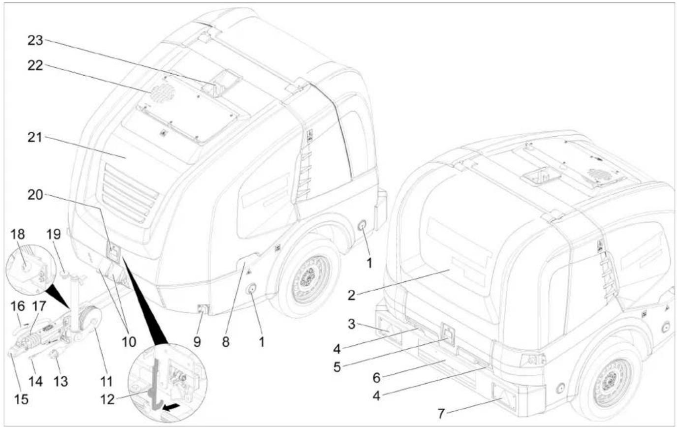
Normal operation display
text_image
1 RM110 OK ON 121h 279.2 5 4 3 2①Fuel tank (bargraph)
② Motor on (ON) or motor off (OFF)
③Liquid softener tank RM110/detergent tank CHEM (OK/empty)
④ Operating hours counter
⑤ Operating hours until next service
Note
The display of the detergent tank is only present if the detergent tank has been detected as full once before. In normal operation, the controller display alternates between the following displays:
- Normal operation
- Service: Due service tasks to be performed by the customer service (see care and service). If multiple maintenance work is due, these are displayed one after another. This display is not shown if no maintenance work is due.
- Fault: Malfunction occurred (see Troubleshooting). If several faults have occurred, these are displayed one after another. This display is not shown if no faults are present.
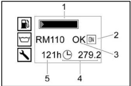
Frost protection display
text_image
1 2 ON① Fuel tank (bargraph)
②Frost protection operating mode
High-pressure gun
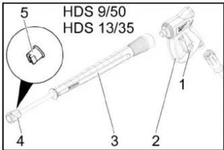
text_image
5 HDS 9/50 HDS 13/35 4 3 2 1① Safety latch of the high-pressure gun
②High-pressure gun
③ Spray lance
④Union nut
⑤ High-pressure nozzle
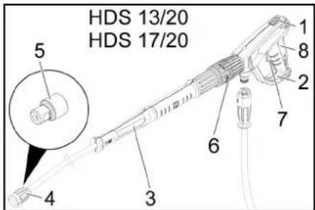
text_image
HDS 13/20 HDS 17/20 5 4 3 6 7 8 1① Safety latch of the high-pressure gun
②EASY!Force high-pressure gun
③EASY!Lock spray lance
④EASY!Lock union nut
⑤ High-pressure nozzle
⑥Pressure/quantity regulator on the high-pressure gun
⑦ Safety lever
⑧Trigger
Initial startup
△WARNING
Risk of injury!
Appliance, accessories, supply lines and connections must be in fault-free condition. If they are not in a perfect condition, the device must not be used.
Set up and align device
ATTENTION
Overheating of the device
Avoid overheating the device.
Ensure that the installation site is sufficiently ventilated.
ATTENTION
Risk of malfunctions and damage to the device.
The device must be in a horizontal position during operation.
- Choose the installation site in a way that the exhaust gas opening is not covered.
- Lock parking brake.
- Lower the support wheel by means of the crank.
- Remove the tear-off rope from the towing vehicle.
- Disconnect the socket plug connection from the vehicle lighting and insert it into the plug storage on the drawbar.
- Secure the device with wheel chocks to prevent it from rolling away.
- Disconnect the towing vehicle.
- Align the device level using the support wheel.
Open/close the front cover
- Actuate the front cover lock. Front cover opens slightly.
- Release the hook catch by pulling it out. The front cover is swung up automatically. When closing, make sure the hook catch engages.
Motor
- Check the oil level of the motor. Do not start up the device if the oil level is below the "MIN" mark.
- Top up with oil if necessary. (see Care and service)
Intermediate transmission
- Check the oil level at the oil-level gauge of the intermediate gearbox.
- Top up with oil if necessary. (see Care and service)
High-pressure pump
- Check the oil level on the oil tank or the oil dipstick of the high-pressure pump.
- Top up with oil if necessary. (see Care and service)
Coolant
- Check the fill level of the coolant in the equalisation container of the motor coolant with a cooled off motor. The fluid level has to be between MIN and MAX.
- Top up with coolant if necessary. (see Care and service)
- Check the antifreeze concentration in the expansion tank.
- Top up with antifreeze if necessary. (see Care and service)
Air filter
-
Check the air filter.
-
Clean/replace the air filter if necessary. (see Care and service)
Filling up the liquid softener
- The liquid softener highly effectively prevents the calcification of the heating coil during operation with hard tap water. This is drip-fed dosed into the float container.
- The dosage is set to medium water hardness at the factory.
Note
A test container of liquid softener is included in the scope of delivery.
- Open filling hole for liquid softener.
- Fill up the liquid softener.
- Close filling hole for liquid softener.
Refuelling
△DANGER
Unsuitable fuel
Risk of explosion
Only use diesel fuel or light heating oil. Unsuitable fuels, such as petrol, must not be used.
Note
When biodiesel B5 (as per EN 14214 - European Standard) is used, no special operating, service and maintenance conditions need to be observed.
Note
When biodiesel B6 to B20 (as per EN 14214 - European Standard) is used, modification measures of the diesel engine are required. Moreover, special operating, service and maintenance conditions must be observed.
Please contact an authorised Yanmar dealer.
- Open the tank cap.
- Fill in diesel fuel via the filling nozzle of the fuel tank.
- Close the tank cap
- Wipe away spilled diesel fuel.
Refilling detergent
HDS 13/20, HDS 17/20 only:
△DANGER
Unsuitable detergents
Risk of injury
Use only KÄRCHER products.
Never fill with solvents (e.g. petrol, acetone, thinners).
Avoid contact with eyes and skin.
Observe the safety and handling instructions of the detergent manufacturer.
Note
Kärcher offers an individual range of cleaning and care products. Your dealer will be happy to advise you.
- Refill/replace the detergent.
Battery
Note
As standard, the device is equipped with a maintenance-free battery.
Safety instructions for the batteries
Be sure to observe the following warnings when handling the batteries:
 | Observe the notes on the battery, in the instructions and in the vehicle operating instructions! |
 | Wear eye protection! |
 | Keep acids and batteries away from children. |
 | Risk of explosion! |
 | Fire, sparks, open flames and smoking are prohibited! |
 | Risk of acid burns! |

First aid!

Warning note!

Disposal!
Do not throw batteries in the bin!
△DANGER
Risk of explosion!
Do not place tools or similar items on the battery. Short-circuit and risk of explosion.
△WARNING
Risk of poisoning!
Never bring wounds into contact with lead. Always clean your hands after working on batteries.
⚠ WARNING
Risk of acid burns!
Wear acid-resistant safety goggles, gloves and apron
Charging the battery
△DANGER
Risk of injury!
Observe the safety regulations when handling batteries and the instruction manual of the charger manufacturer. Only charge the battery using a suitable charger.
- Disconnect the battery.
- Connect the plus cable of the charger to the plus terminal of the battery.
- Connect the minus cable of the charger to the minus terminal of the battery.
- Insert the mains plug and switch on the charger.
- Charge the battery with the lowest possible charging current.
Mounting the high-pressure gun, spray lance, nozzle and high-pressure hose
- Connect the spray lance to the trigger gun.
- Tighten the screw connection of the spray lance fingertight.
- Place the high-pressure nozzle into the union nut.
- Fit the union nut and hand-tighten.
- Connect the high-pressure hose to the high-pressure gun.
ATTENTION
Risk of damage!
High-pressure hose is pressurised
Always unroll the high-pressure hose completely. HDS 13/20, HDS 17/20 only:
Note
The EASY!Lock system connects components quickly and safely via a single turn of the quick-release thread.
Water connection
See the "Technical data" for the connected loads.
- Unroll the water hose from the hose reel and connect it to the water inlet (e.g. tap).
Filling water tanks
- Open the supply tap of the water reservoirs.
- Unroll the water hose from the hose reel and connect it to the water inlet (e.g. tap).
- Open water inlet.
The water reservoirs are filled via the float container. When the water reservoirs are filled, the float valve in the float container closes.
- Close the water inlet.
- Disconnect the water hose from the water inlet.
- Roll the water hose onto the hose reel.
Operation
△DANGER
Flammable fluids
Risk of explosion
Do not spray inflammable liquids.
△DANGER
Operation without spray lance
Risk of injury
Never operate the device without the spray lance installed.
Before each use, check that the spray lance is firmly seated. The screw connection of the spray lance must be tightened hand tight.
△DANGER
High-pressure water jet
Danger of injury
Never fasten the trigger and safety lever in the actuated position.
Do not use the high-pressure gun when the safety lever is damaged.
Push the safety latch of the high-pressure gun forwards every time before starting work with the device.
Hold the high-pressure gun and spray lance with both hands.
ATTENTION
Operation with an empty fuel tank
Destruction of the fuel pump
Never operate the device with an empty fuel tank.
Opening/closing the high-pressure gun
- Opening the high-pressure gun: Actuate the safety lever and trigger.
- Closing the high-pressure gun: Release the safety lever and trigger.
Changing nozzles
△DANGER
Risk of injury!
The high-pressure gun is pressurised.
Turn off the device before changing the nozzle and operate the high-pressure gun until the device is depressurised.
- Switch off the device and operate the high-pressure gun until the device is depressurised.
- Secure the high-pressure gun by pushing the safety latch forwards.
- Change the nozzle.
Water supply
The water supply can either take place via an external water supply or via the internal water reservoirs (2x250 litres).
Ball tap of return switchover
- Position parallel to travel direction: The return water from the high-pressure pump flows into the float tank when the overflow valve is open.
Note
If the trigger gun is closed in this ball tap position, the device may switch off after a few minutes due to too high temperature (see Troubleshooting/ERROR 3).
- Position lateral to travel direction: The return water of the high-pressure pump flows into the water reservoirs when the overflow valve is open.
External water supply
- Place the actuation lever of the return flow valve ball tap parallel to the travel direction (20L).
- Close the supply tap of the water reservoir.
Internal water supply
- Set the actuation lever of the return flow valve ball tap lateral to the travel direction (500L).
- Open the supply tap of the water reservoirs.
Turning on the device
Note
The device can only be operated when the front cover is closed. If the front cover is opened, the device shuts down and the indicator light is on.
Note
Due to the bleeding procedure, the speed of the motor may vary until the final operating pressure has been reached.
- Unlock the emergency-stop switch by pulling.
- Open rear cover
- Establish the water supply.
- Insert the key into the key switch.
- With cold motor only: To preheat the motor, turn the key switch to the left and hold it until the indicator light for preheating goes out.
- Turn key switch to position "l".
The standby mode indicator light lights up. The control voltage is switch on and the display shows the operating state.
- Turn the key switch to the right until the motor is running.
- Set the power switch to operation with cold/hot water.
-
Unlock the high-pressure gun by pushing the safety latch backwards.
-
Open the high-pressure gun.
Cold water operation
- Set the power switch to "0/OFF" (burner off).
Operation with hot water
△DANGER
Hot water
Risk of scalding
Avoid contact with hot water.
- Set the power switch to the desired work temperature (max. 100 °C). The burner is switches on.
Speed control
HDS 9/50, HDS 13/35 only (optional with HDS 13/20, HDS 17/20):
Note
If the motor speed is increased, the operating pressure also rises. This can be read from the pressure gauge.
- Increasing the speed:
- Push up the lever of the speed control.
- Reducing the speed:
- Push down the lever of the speed control.
Setting the working pressure and flow rate
HDS 13/20, HDS 17/20 only:
- Adjust the working pressure and flow rate by turning the pressure/quantity control at the high-pressure gun (+/-).
△DANGER
Risk of injury!
Take care to ensure that the spray lance screw connection does not release when adjusting the pressure/quantity control.
Operation with detergent
HDS 13/20, HDS 17/20 only:
ATTENTION
Damage from unsuitable detergents
Unsuitable detergents may damage the device and the object to be cleaned.
Only use the detergent intended for the object.
- Use detergents sparingly to conserve the environment.
- Observe the recommended dosage and instructions provided with the detergents.
- Only detergents that have been approved by the device manufacturer may be used.
- Kärcher detergents ensure fault-free operation. Ask us for a consultation, request our catalogue or our detergent information sheets.
- Place the detergent suction hose in a container filled with detergent and tighten the screw cap.
- Set the detergent dosing valve to the desired concentration.
Note
To prevent detergent from flowing back into the float tank or water reservoirs when operating with detergent and a closed trigger gun, the detergent dosing valve must be closed.
Removal of weeds
HDS 13/20, HDS 17/20 only (option):
Note
The speed control attachment kit (option, ex works: 2.013-086.7, retrofit kit: 2.013-014.0) is absolutely essential for operating the weed removal system! Operation in accordance with the operating instructions for weed removal WR 10, part no. 5.968-256.0 or WR 20/WR 50/WR 100, part no. 5.967-455.0!
The following information must also be observed:
- Install WR 10, 20, 50 or 100 onto the spray lance and insert the appropriate nozzle (see corresponding operating instructions).
- Turn key switch to position "I". The standby mode indicator light lights up. The control voltage is switch on and the display shows the operating state.
- Push the lever of the speed control down as far possible.
Weed Removal V2.0
- Set the power switch to the "Weed removal V2.0" operating mode.
- Turn the key switch to the right until the motor is running.
- Unlock the high-pressure gun by pushing the safety latch backwards.
- Open the high-pressure gun.
- TEMP LOW appears on display: It takes about 2 - 4 minutes before the work temperature has been reached.
● TEMP OKAY appears on display:
- Perform weed removal.
Weed Removal V3.0 & V5.0
- Set the power switch to the "Weed removal V3.0 & V5.0" operating mode.
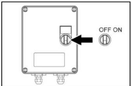
text_image
OFF ON- Switch on the WR box, set the switch to "ON".

text_image
ESM3710-N SET P ✓ EMKO 8.8:8.8- Adjust the temperature using SET and the v buttons. Confirm with (setting range, 85-105 °C).
- Turn the key switch to the right until the motor is running.
- Unlock the high-pressure gun by pushing the safety latch backwards.
- Open the high-pressure gun.
Note
It takes about 2 - 4 minutes before the work temperature has been reached.
- Perform weed removal.
Steam mode (steam cleaning and disinfection)
HDS 13/20, HDS 17/20 only (option):
Note
The speed control attachment kit (option, ex works: 2.013-086.7, retrofit kit: 2.013-014.0) is absolutely essential for operation in steam mode!
△DANGER
Risk of scalding!
Increased working pressure due to high work temperature.
Keep in mind that at work temperatures above 105 °C, the working pressure must not exceed 3.2 MPa (32 bar).
Note
Operation with 2 spray lances is not possible for steam cleaning.
1. Steam cleaning: Fit the appropriate steam nozzle to the spray lance (see technical data for part no.).
2. Disinfection: Mount WR 10, 20, 50, or 100 on the spray lance and insert the appropriate steam nozzle (see Technical Data for part number).
3. Set the power switch to the "steam mode" operating mode.
4. Switch on the WR box, set the switch to "ON".
5. Adjust the temperature using SET and the v buttons. Confirm with (recommended setting range, 120-155 °C).
6. Turn the key switch to the right until the motor is running.
7. Open the bonnet and turn the handwheel on the overflow valve anti-clockwise according to the pressure gauge to 30 bar.
8. Unlock the high-pressure gun by pushing the safety latch backwards.
9. Open the high-pressure gun.
Note
It takes about 2 - 4 minutes before the work temperature has been reached.
10. Carry out steam cleaning or disinfection.
Safety functions
1 WR-Box indicator light lights up red System pressure too high, burner switches off, see Help with faults.
2 ERROR 5 appears on the display on the control panel: System pressure too low, the burner does not start, see Help with faults/ERROR 5.
Interrupting operation
- Close the high-pressure gun.
- Lock the high-pressure gun by pushing the safety latch of the high-pressure gun to the front.
Note
When the high-pressure gun is closed, the motor continues to run at idling speed. This way the water circulates between the float container and the high-pressure pump and heats up. If the maximum admissible temperature (55 °C) is reached, the motor is switched off by the temperature sensor at the water inlet. After it has cooled down to below 50 °C, the device can be put in operation again.
After operation with detergent
HDS 13/20, HDS 17/20 only:
- Set the detergent dosing valve to "0"
- Flush the device clean for at least 1 minute with the high-pressure gun open.
Switching off the device
△DANGER
Risk of injury from hot water or steam
Risk of scalding
After operation with hot water or steam, the device must be operated with the gun opened with cold water for at least two minutes to cool it down.
ATTENTION
Risk of damage!
Risk of damage
Never switch off the motor under full load with the trigger gun open.
- Set the power switch to "0/OFF" (burner off).
- Close the trigger gun.
Motor regulates to idle speed.
- Turn key switch to position "0".
The Standby mode indicator light goes out. The control voltage is switched off and the display goes out.
-
With external water supply: Close the water inlet.
-
Actuate the high-pressure gun until the device is depressurised.
- Secure the high-pressure gun with the safety latch against unintentional opening.
- With external water supply: Disconnect the water hose from the water inlet and coil up the water hose onto the hose reel.
- Coil the high-pressure hose onto the hose reel.
Antifreeze
To protect from freeze damage, the device must be flushed with antifreeze.
Note
Use normal glycol-based anti-freezing agents for auto-mobiles.
Note
Observe the handling instructions of the anti-freeze manufacturer.
This also provides a certain degree of corrosion protection.
Motor antifreeze
- Check the coolant circuit of the motor for sufficient antifreeze, refill antifreeze as needed.
- See Maintenance Procedures "Check and refill the coolant".
Battery frost protection battery
- If the device is not used for an extended period and if there is frost, remove the battery and store it in a location protected from frost.
Antifreeze rinse in the circuit (high pressure pump)
- With external water supply: Disconnect the water hose from the water inlet.
- Set the power switch to "0/OFF" (burner off).
- Depressurise the device
- Set the power switch to the operating mode "frost protection".
- HDS 13/20, HDS 17/20 only: Set dosing valve for detergent to maximum. Pull the detergent suction hose out of the detergent container and place it in such a way that it can be sucked empty.
natural_image
Pure technical line drawing of a mechanical assembly without any text, numbers, or symbols- Open the supply tap of the water reservoirs and the drain tap in order to completely drain the device.

natural_image
Pure technical line drawing of mechanical components without any text, numbers, or symbolsThe filling level indicator of the water reservoirs dips completely.
- Close the supply tap of the water reservoirs and the drain tap.
- Disconnect the high-pressure gun from the high-pressure hose.
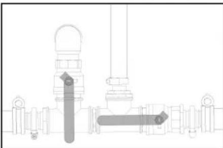
natural_image
Technical line drawing of a mechanical assembly with no visible text or symbols- Connect the high-pressure hose to the frost protection inlet.
- Connect the water hose to the return flow of the frost protection.
- Prepare the antifreeze in the antifreeze container. Select the mixing ratio of the water/antifreeze as per the instructions of the antifreeze manufacturer.
- Check the antifreeze concentration with a commercially available antifreeze tester and adapt if necessary.
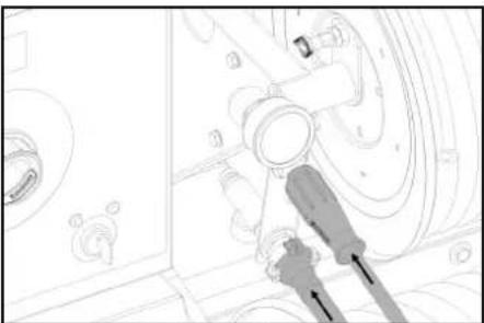
natural_image
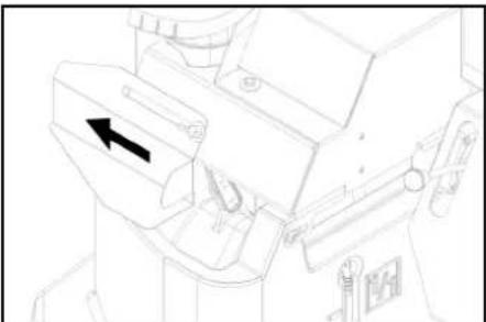
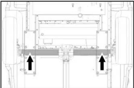
Technical line drawing of a mechanical component with an arrow indicating direction (no text or symbols)- Open the filling hole of the float container. In order to do so, loosen the wing screw and push the cover to the left.
- Fill 20 litres of antifreeze into the float container and close the filling hole.
- Align the actuation lever of the ball tap for antifreeze vertically.
- Place the actuation lever of the return flow valve ball tap parallel to the travel direction (20L).
- With cold motor only: To preheat the motor, turn the key switch to the left and hold it until the indicator light for preheating goes out.
- Turn key switch to position "I". The standby mode indicator light lights up. The control voltage is switch on and the display shows the operating status "Antifreeze".
- Turn the key switch to the right until the motor is running.
The antifreeze liquid is pumped through the device in a circuit.
- Lead the residual water via the frost protection hose into the anti-freeze container.
- As soon as antifreeze exits the antifreeze hose, put the operating lever of the frost protection ball tap in the horizontal position and wait for 5 seconds.
- Switch off the engine.
- Set the power switch to "0/OFF" (burner off).
Pumping antifreeze out of the high pressure system
Note
Prior to operation, the antifreeze must be pumped from the high-pressure system back into the antifreeze container
1. Align the actuation lever of the ball tap for antifreeze vertically.
- Connect the high-pressure hose to the frost protection inlet.
- Connect the water hose to the return flow of the frost protection.
- Open the filling hole of the float container. In order to do so, loosen the wing screw and push the cover to the left.
- Fill 20 litres of fresh water into the float container and close the filling hole.
- Set the power switch to the operating mode "frost protection".
- With cold motor only: To preheat the motor, turn the key switch to the left and hold it until the indicator light for preheating goes out.
- Turn key switch to position "I". The standby mode indicator light lights up. The control voltage is switch on and the display shows the operating status "Antifreeze".
- Turn the key switch to the right until the motor is running.
The antifreeze fluid is forwarded from the float container into the antifreeze container with fresh water. - Rinse for approx. 2 minutes until the antifreeze container is filled.
- Switch off the engine.
- Set the power switch to "0/OFF" (burner off).
Transport
CAUTION
Risk of injury and damage!
Improper transportation Mind the weight of the device during transport.
ATTENTION
Risk of damage!
Improper transportation
Protect the trigger from damage during transport.
Trailer operation
Note: The driver driving the towing vehicle on public roads must ensure that he/she has the appropriate license for this (driving license class).
△DANGER
Unpredictable driving behaviour
With a partially filled water reservoir, the device can rock up or tip over under extreme steering movements or braking situations.
Drain or fill the water reservoir before driving.
- With a permissible total weight of 1600 kg, fill or empty the water reservoir completely. With a permissible total weight of 1100 kg, empty the water reservoir completely.
- On devices without a hose reel, unscrew the high-pressure hose from the high-pressure outlet and stow it in the device.
- Pivot the front bar (option) forwards and lock in place.
- Pull the rear tarpaulin (option) down an lock in place.
- Use the support wheel to adjust the tow bar to the height of the towing hitch on the towing vehicle.
- Attach the tear-off rope to the towing vehicle.
text_image
A B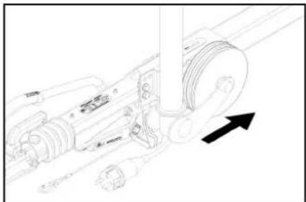
natural_image
Technical line drawing of a mechanical assembly with no visible text or symbols- Remove the chocks from the wheels and insert them into the holders.
- Release the parking brake.
- Check that the trailer lighting system (brake lights, indicator lights, tail lights, license plate light) is functioning correctly.
- Check the running surfaces of the tyres for embedded objects.
- Check the condition of the tyres.
- Check the tyre pressure, see "Maintenance work". Note: Note the locally applicable speed limits for vehicles with trailers and adhere to these.
Crane transport
△DANGER
Improper crane transport
Risk of injury from a falling device or falling objects Observe the local regulations for accident prevention and the safety instructions.
The device may only be transported with a crane by persons instructed in the operation of the crane.
Check the lifting gear for damage before each crane transport.
Check the handle for damage before each crane transport.
Lift the device only by the handle.
Do not use an slinging chains.
Secure the lifting gear against unintentional unhooking of the load.
Remove the spray lance with high-pressure gun, nozzles, surface cleaner and other loose objects before transporting by crane.
Do not transport any objects on the device during the lifting operation.
Do not stand under the suspended load.
Ensure that no persons are in the hazard zones of the crane.
Do not leave the device handing unattended on the crane.
Storage
△CAUTION
Risk of injury or damage due to non-observance of the weight!
When transporting and storing the device, there is a risk of injury and damage due to its weight.
Take into account the weight of the device for transportation and storage, see chapter Technical data.
ATTENTION
Risk of damage due to frost!
Water that is not completely drained can damage the device and accessories during freezing.
Empty the water completely from the device and accessories.
Protect the device and accessories from frost.
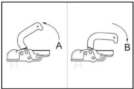
① Towing hitch open
② Towing hitch closed
- Pull the coupling lever up (open).
- Fit the tow bar onto the towing hitch ball.
- Press the coupling lever down (close) until it lies parallel to the tow bar.
- Plug in the socket plug connection for the vehicle lighting.
- Rotate the support wheel up by means of the crank.
- Ensure that the support wheel points toward the trailer when fully retracted.
Care and service
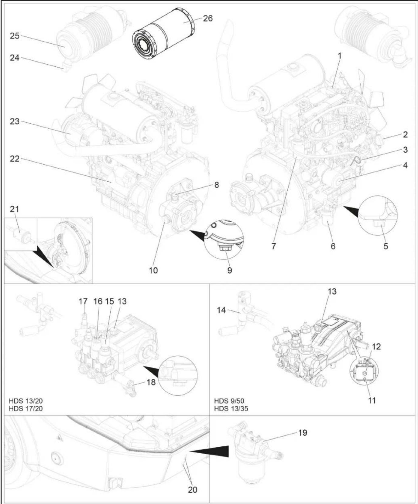
text_image
25 24 23 22 21 10 26 1 2 3 4 7 6 5 9 8 HDS 13/20 HDS 17/20 17 16 15 13 18 14 13 12 11 HDS 9/50 HDS 13/35 20 19① Motor oil filling hole (top)
② Motor oil filling hole (lateral)
③Oil dipstick (motor)
④Oil filter (motor)
⑤Oil drain screw of motor
⑥ Water separator
⑦ Fuel filter
⑧ Filling hole for transmission oil incl. venting
⑨ Oil drain screw of intermediate transmission
⑩Oil sight glass for intermediate gearbox
⑪ Pump oil drain screw
⑫Oil sight glass pump
⑭Safety block of burner
⑮Frost protection rinsing valve
⑯Pressure switch
⑰Overflow valve
⑱Detergent inlet
⑲Pump prefilter
⑳ Inspection slot
②1 Fuel filter
⑳Starter
23Alternator
⑳Dirt outlet at the air filter
25 Air filter
②6 Air filter insert
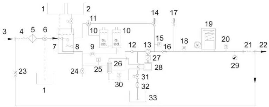
Flow chart
flowchart
graph TD
    A["1"] --> B["2"]
    B --> C["10"]
    C --> D["9"]
    D --> E["8"]
    E --> F["7"]
    F --> G["6"]
    G --> H["5"]
    H --> I["4"]
    I --> J["3"]
    J --> K["23"]
    K --> L["1"]
    L --> M["24"]
    M --> N["25"]
    N --> O["26"]
    O --> P["30"]
    P --> Q["31"]
    Q --> R["32"]
    R --> S["33"]
    S --> T["34"]
    T --> U["35"]
    U --> V["36"]
    V --> W["37"]
    W --> X["38"]
    X --> Y["39"]
    Y --> Z["40"]
    Z --> AA["41"]
    AA --> AB["42"]
    AB --> AC["43"]
    AC --> AD["44"]
    AD --> AE["45"]
    AE --> AF["46"]
    AF --> AG["47"]
    AG --> AH["48"]
    AH --> AI["49"]
    AI --> AJ["50"]
    AJ --> AK["51"]
    AK --> AL["52"]
    AL --> AM["53"]
    AM --> AN["54"]
    AN --> AO["55"]
    AO --> AP["56"]
    AP --> AQ["57"]
    AQ --> AR["58"]
    AR --> AS["59"]
    AS --> AT["60"]
    AT --> AU["61"]
    AU --> AV["62"]
    AV --> AW["63"]
    AW --> AX["64"]
    AX --> AY["65"]
    AY --> AZ["66"]
    AZ --> BA["67"]
    BA --> BB["68"]
    BB --> BC["69"]
    BC --> BD["70"]
    BD --> BE["71"]
    BE --> BF["72"]
    BF --> BG["73"]
    BG --> BH["74"]
    BH --> BI["75"]
    BI --> BJ["76"]
    BJ --> BK["77"]
    BK --> BL["78"]
    BL --> BM["79"]
    BM --> BN["80"]
    BN --> BO["81"]
    BO --> BP["82"]
    BP --> BQ["83"]
    BQ --> BR["84"]
    BR --> BS["85"]
    BS --> BT["86"]
    BT --> BU["87"]
    BU --> BV["88"]
    BV --> BW["89"]
    BW --> BX["90"]
    BX --> BY["91"]
    BY --> BZ["92"]
    BZ --> CA["93"]
    CA --> CB["94"]
    CB --> CC["95"]
    CC --> CD["96"]
    CD --> CE["97"]
    CE --> CF["98"]
    CF --> CG["99"]
    CG --> CH["100"]
① Antifreeze container
②Liquid softener container
③ Water inlet
④ Low-pressure hose reel
⑤ Water inlet filter
⑥ Frost protection ball tap
⑦ Float container
⑧ Water shortage safeguard
⑨ Supply tap of water reservoirs
⑩Water reservoir
⑪ Ball tap of return switchover
12 Pump prefilter
⑬ High-pressure pump
14 Overflow valve
15 Pressure switch
16 Check valve
17 Safety valve
⑱Flow switch
19 Booster heater
⑳Temperature sensor of the burner
②1High pressure hose reel
②2High-pressure outlet
②3Backflow frost protection
24 Drain tap
⑲Temperature sensor water inlet
26 Heat exchanger
27 Intermediate transmission
28 Diesel engine
29 Pressure gauge
③0 Temperature sensor for cooling water
③1 Detergent solenoid valve
③2 Detergent dosing valve
③3 Detergent container
Customer Service display
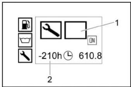
text_image
-210h 610.8 1 2| Symbol Type of Customer Service | |
 | Burner service |
 | Motor service |
 | Pump service |
 | High-pressure gun service |
Maintenance intervals
| Time & date Activity By whom | ||
| Before each journey Check lighting. Operator | ||
| Check the tyre pressure and condition of the tyres. Operator | ||
| Daily Check the condition of the oil in the high-pressure pump sight glass. Do not start up the device if the oil is milky. Notify Customer Service.ATTENTIONRisk of damage!In case of lacteous oil, inform Kärcher customer service immediately | Operator | |
| General visual inspection of the device. Operator | ||
| Check the high-pressure hose for damage. Do not continue using damage high-pressure hoses. | ||
| Check the water inlet filter, clean if necessary Operator | ||
| Check the pump prefilter, clean if necessary. Operator | ||
| Check oil level on the motor, refill oil if necessary. | ||
| Check oil level at the intermediate gearbox, refill oil if necessary. | ||
| Check the fuel filter on the motor, inform customer service if necessary. | ||
| Check the water separator on the motor, inform customer service if necessary. | ||
| Check coolant level in the equalisation container, refill coolant if needed. | ||
| Check fuel filter, contact customer service if necessary. | ||
| Check the filter on the detergent suction hose, clean if necessary. | ||
| Check line system for leaks. | ||
| Once after the first 50 operating hours | Check the V-belt tension at the fan, retention if necessary. | Operator |
| Replace oil in the motor. | Customer Service department | |
| Change the oil in the high pressure pump. | Customer Service department | |
| Every 50 operating hours or 3 months | Check the battery. | Customer Service department |
| Time & date | Activity | By whom |
| Every 200 operating hours | Check the air filter or air filter inlay, clean if necessary. | Operator |
| Check the V-belt tension at the fan, retention if necessary. Operator | ||
| Check the intermediate gearbox for leaks. Customer Service | department | |
| Clean the sieve on the filling nozzle of the fuel tank. Customer Service | department | |
| Replace oil in the motor. Customer Service | department | |
| Replace oil filter inlay on motor. Customer Service | department | |
| Perform maintenance tasks in accordance with the maintenance plan. Customer Service | department | |
| Every 400 operating hours or annually | Replace the air filter insert. | Operator |
| Check fuel filter, replace if necessary. | Customer Service department | |
| Perform maintenance tasks in accordance with the maintenance plan. Customer Service | department | |
| Every 600 operating hours or annually | Change the oil in the high pressure pump. | Customer Service department |
| Every 800 operating hours. | Check the blower motor for proper function, replace sliding contacts (carbon brushes) if necessary. | Operator |
| Every 1000 operating hours or annually. | Replace coolant. | Customer Service department |
| Every 1000 operating hours. | Replace oil in the intermediate gearbox. | Customer Service department |
| Replace V-belt on the ventilator. | Customer Service department | |
| Check the valve clearance at the cylinder head of the motor, adjust if necessary. | authorized Yan-mar dealer | |
| Every 1600 operating hours. | Check injectors on the motor, clean if necessary. | authorized Yan-mar dealer |
| Check the crankshaft casing ventilation on the motor, clean if necessary. | authorized Yan-mar dealer | |
| Every 2000 operating hours or every 2 years | Replace fuel hoses on the motor. | authorized Yan-mar dealer |
| Replace cooling system hoses on the motor. | authorized Yan-mar dealer | |
| Every 2000 operating hours | Check the valves and valve seats on the cylinder head of the motor, lap if necessary. | authorized Yan-mar dealer |
| Only applies to devices with vapour mode attachment kit: | ||
| Recurring every 5 years at the latest | Perform the pressure test according to the manufacturer's specifications. | Customer Service department |
Maintenance work
△DANGER
Turn the key-operated switch to off and remove the key before performing any work on the device.
△DANGER
Risk of injury from electric shock
Do not place metallic objects on the alternator or the starter.
△DANGER
Risk of explosion!
Risk of injury and damage
Do not place any tools or objects on the battery, i.e. on the end poles and cell connectors.
Naked flames and smoking must be strictly avoided. Ensure the room is well ventilated when charging batteries.
Only use batteries and chargers approved by Kärcher (original spare parts).
- Allow the device to cool down.
Cleaning the water inlet filter
-
Disassemble the water inlet filter and take out the filter inlay.
-
Clean the filter with clean water or compressed air.
-
Assemble in the reverse order
Cleaning the pump prefilter
-
Depressurise the device.
-
Disassemble the pump prefilter and take out the filter inlay.
-
Clean the filter with clean water or compressed air.
-
Assemble in the reverse order.
Clean the filter on the detergent suction hose
-
Unscrew the screw cap of the detergent suction hose.
-
Take out detergent suck hose
-
Clean filter in water and reinstall.
Check the oil level on the motor and top up
Note
The filling quantity between the MIN and MAX markings on the oil dipstick is 1.6 litres.
-
Remove the oil dipstick, wipe it and reinsert it.
-
Remove the oil dipstick one more time and check the oil level.
The oil level is correct if it is within the markings on the oil dipstick.
-
If the oil level is below the mark, open the filling hole lid and add fresh motor oil.
-
Wait five minutes, until the oil has collected in the oil pan.
-
Check the oil level as described above.
-
Repeat this procedure as often as necessary until the oil level is between the markings on the oil dipstick.
-
After the check, insert the oil dipstick and close the lid of the filling hole.
Note
The air bubbles must be able to escape.
For oil type refer to technical specifications
Check the oil level on the intermediate gearbox and refill transmission oil
- Check the oil level at the oil-level gauge of the intermediate gearbox.
The oil level is correct if it is in the middle of the oil-level gauge.
-
If the oil level is below the middle of the oil-level gauge, open the lid of the filling hole and fill in fresh transmission oil.
-
Close filling hole.
Note
The air bubbles must be able to escape.
For oil type refer to technical specifications
Check the oil level on the oil dipstick of the high-pressure pump, refill oil if necessary
-
Remove the oil dipstick, wipe it and insert it again.
-
Remove the oil dipstick again and check the oil level.
The oil level is correct if it is within the markings on the oil dipstick.
-
If the oil level is below the mark on the oil dipstick, fill up with fresh oil.
-
Twist in the oil dipstick.
Note
Air bubbles must be able to escape.
For oil type refer to technical specifications
Check the coolant and refill
△CAUTION
Harmful substances can be produced.
Observe the brand of antifreeze used.
The mixture can cause a chemical reaction.
Do not mix different types of antifreeze.
△WARNING
Risk of motor overheating
A lack of coolant can cause the motor to overheat.
Switch off the motor immediately and allow it to cool down.
△WARNING
Risk of motor overheating
A lack of coolant can cause the motor to overheat. If the motor overheats to the point where steam escapes, turn off the motor and maintain a safe distance until the pressure has decreased.
ATTENTION
Danger of scalding from motor coolant
The expansion tank is pressurised.
Never open the lid on the expansion tank of the motor coolant at operating temperature.
- Open the lid on the expansion tank of the motor coolant, fill in fresh clean water and the required antifreeze.
Check/clean the air filter
Note
For a coarse cleaning of the air filter, hold the catch pan under the dirt outlet and operate the dirt outlet.
Note
Heavily soiled or defective filter inlays must always be replaced.
-
Loosen the spring tension bracket, remove the cover and eliminate the dust deposits.
-
Take out the filter inlay.
-
Blow out the filter inlay with compressed air (max. 2 bar) from the inside.
- Clean the inside of the air filter housing with a cloth.
- Insert the filter inlay into the air filter casing.
- Attach the cover and fasten it by means of the spring tension bracket.
Check the ventilator V-belt
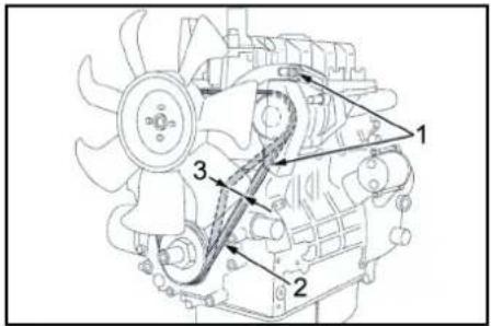
text_image
Technical diagram of a mechanical engine with numbered components labeled 1, 2, and 3① Fastening screws of generator
②V-belt
③ Belt tension approx. 7-9 mm
Note
If the V-belt is not sufficiently tensioned, this can cause overheating of the motor or insufficient battery charge.
- Shut off the motor and remove the key from the key switch.
- Press the belt with your thumb to check the V-belt tension.
Note
You should be able to push the V-belt in by approx. 7-9 mm.
Note
The defective V-belts must be replaced immediately.
Lubricating the inertia brake
- Use a commonly available grease gun to inject the appropriate grease into both grease nipples.
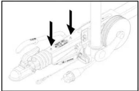
natural_image
Technical line drawing of a mechanical assembly with arrows indicating motion or force directions (no text or symbols present)①Grease nipple
Checking the tyre pressure
- Place the device on a level surface.
- Connect the tyre pressure gauge device to the tyre valve.
- Check the type pressure (see "Technical data") and correct if necessary.
Changing a wheel
△DANGER
Risk of fatal injury from moving traffic
Park the device on a level surface and wear high-visibility clothing when carrying out repair work on public roads.
- Park the device on a level surface.
- Check that the ground is stable. Additionally secure the device against rolling away with a wheel chock
- Lock parking brake.
- Check the tyres.
- Check the tyre running surfaces for embedded objects.
- Remove objects found.
- Use suitable, commercially available materials to carry out tyre repairs.
Note
Observe the manufacturer's recommendations. The journey may be resumed providing that the directions supplied by the product manufacturer have been observed. The tyre/wheel change should nonetheless be carried out as soon as possible.
natural_image
Technical line drawing of a mechanical assembly with two directional arrows indicating movement or force directions (no text or symbols present)- Place the jack at the relevant position point.
- Loosen the wheel screws.
- Lift the device with a jack.
- Unscrew the wheel bolts.
- Remove the wheel.
- Mount spare wheel.
- Apply the wheel bolts.
- Lower the device with the jack.
- Tighten the wheel screws crosswise.
Tightening torque 110-120 Nm
Note
No jack included in the scope of delivery.
Note
Use a suitable, commonly available jack.
Trailer
- Have the brake system and the Chassis and Suspension checked regularly by an authorised dealer workshop.
Troubleshooting guide
△DANGER
Inadvertently starting up device
Risk of injury, electric shock
Turn the key-operated switch to "0" and remove the key before performing any work on the device.
△DANGER
Inadvertently starting up device, touching live com- ponents
Risk of injury, electric shock
Switch off the device before performing any work on the device.
Remove the mains plug.
△DANGER
Risk of explosion and short-circuit. Do not place any tools or similar on the battery.
1 Allow the device to cool down.
Display malfunction
text_image
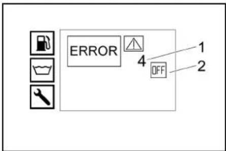
ERROR 4 OFF 1 2① Fault number
② Motor off (OFF)
Customer Service department
If the malfunction cannot be corrected, the device must be checked by the Customer Service department.
Malfunctions with information shown on the display
| Fault | Cause | Rectification | Person responsible |
| ERROR 1 Charging current | V-belt tension on the fan too low. | 1. Retension the V-belt on the fan. | Operator |
| Alternator defective. 1. Check alternator, replace if necessary. Customer Service depart-ment | |||
| Charging current monitoring defective. | 1. Check wiring + relay K9. | Customer Service depart-ment | |
| ERROR 3 Temperature of water inlet or cooling water | Water temperature in the float container too high due to circulation mode. | 1. Allow the water to cool down or drain it. Set the ac-tuation lever of the return flow valve ball tap lateral to the travel direction (500L). | Operator |
| Temperature sensor of water inlet has switched off the device | 1. Turn the device off and back on. If the malfunction occurs repeatedly, notify customer service. | Operator | |
| Temperature sensor of water inlet defective. | 1. Replace the temperature sensor. | Customer Service depart-ment | |
| Coolant level too low. | 1. Fill coolant into the expansion tank. | Operator | |
| V-belt tension on the fan too low. 1. Retension the V-belt on the fan. Operator | |||
| Temperature sensor for cooling water on the motor defective. | 1. Replace the temperature sensor. | Customer Service depart-ment | |
| Fault | Cause | Rectification | Person responsible |
| ERROR 4 Water shortage External water supply: Water inlet pressure too low. | 1. Check the water inlet. Operator | ||
| Internal water supply: Water reservoirs em-pty. | Fill water reservoirs. Operator | ||
| Water shortage safeguard in the float contain-er defective. | Replace the water shortage safeguard. Customer Service department | ||
| Water inlet filter dirty. 1. Clean the water inlet filter. Operator | |||
| Water hose leaky or kinked. 1. Replace water hose. Customer Service depart-ment | |||
| Float valve in the float container is soiled. | Clean float valve. Customer Service depart-ment | ||
| Float valve in the float container jammed or defective. | Clean or replace the float valve. Customer Service depart-ment | ||
| ERROR 5 Flow switch / pressure switch | Flow switch defective. 1. Replace flow switch. | Customer Service depart-ment | |
| Pressure switch faulty. | Replace the pressure switch. | Customer Service depart-ment | |
| Overflow valve is defective. | Replace overflow valve. | Customer Service depart-ment | |
| Check valve in the overflow valve defective. | Replace the check valve. | Customer Service depart-ment | |
| Pump prefilter dirty. 1. Clean the pump prefilter. Operator | |||
| Steam mode: System pressure too low | Raise the system pressure in small increments by turning the handwheel on the overflow valve clockwise. | Operator | |
| ERROR 6 Fuel sensor | Fuel tank empty. | Refuel. | Operator |
| Float of the fuel sensor jammed. | Check the float. | Customer Service depart-ment | |
| Fuel sensor defective. | Replace fuel sensor. | Customer Service depart-ment | |
| ERROR 9* Emission temperature | Exhaust gas thermostat has responded and switched off the burner. | Switch off the device, allow to cool down and restart. If the malfunction occurs repeatedly, notify customer service. | Operator |
| Exhaust gas thermostat defective. | Replace the exhaust gas thermostat. | Customer Service depart-ment | |
| Burner has been wrongly set. | Adjust the burner. | Customer Service depart-ment | |
| Heating coil soiled or calcified. | Decarbonise or descale heating coil. | Customer Service depart-ment | |
| ERROR 10* Burner temperature Cleaning operation with cold water is possible. | Temperature sensor for burner (NTC) has switched off the burner. | Turn the device off and back on. If the malfunction occurs repeatedly, notify customer service. | Operator |
| Temperature sensor of the burner is defec-tive. | Replace the temperature sensor. | Customer Service depart-ment | |
| ERROR 11* Flame sensor (no flame) Cleaning operation with cold water is possible. | Nozzle holder soiled. | Clean the nozzle holder. | Customer Service depart-ment |
| Ignition electrodes have been set up wrongly or are dirty. | Properly adjust or clean the ignition electrodes. | Customer Service depart-ment | |
| Photo cell of the flame monitoring defective. | Replace the photo cell. | Customer Service depart-ment | |
| Fuel pump defective. | Replace fuel pump. | Customer Service depart-ment | |
| Solenoid valve fuel is defective. | Replace the solenoid valve. | Customer Service depart-ment | |
| Fuel filter choked. | Replace fuel filter. | Customer Service depart-ment | |
| Ignition transformer defective. | Replace the ignition transformer. | Customer Service depart-ment | |
| ERROR 12* Flame sensor (flame does not go out) Cleaning operation with cold water is possible. | Photo cell of the flame monitoring defective. | Replace the photo cell. | Customer Service depart-ment |
| Burner sooted, "afterglow". | Have the burner decarbonised. | Customer Service depart-ment | |
| ERROR 14 Switch-off after 45 minutes continuous break | Standby time of 45 minutes exceeded. | Turn the device off and back on. | Operator |
| ERROR 15 Switch-off after 45 minutes continuous operation | Continuous operation exceeds 45 minutes. | Turn the device off and back on. | Operator |
Troubleshooting with nothing shown on the display
| Fault | Cause | Rectification | Person responsible |
| Device stops, display switches off | Blown fuse. | 1. Replace fuse. | Operator |
| No power supply to inverter because of battery undervoltage or overvoltage. | 1. Check battery, charge if necessary. | Operator | |
| Inverter defective. | 1. Replace inverter. | Customer Service department | |
| No display after switching the device on | Battery depleted. 1. Charge the battery. Operator | ||
| Blown fuse. 1. Replace fuse. Operator | |||
| Front cover open. 1. Close front cover. Operator | |||
| Emergency stop switch depressed. 1. Unlock | the emergency-stop switch by pulling. Operator | ||
| No power supply to inverter because of battery undervoltage or overvoltage. | 1. Check battery, charge if necessary. Operator | ||
| Inverter defective. 1. Replace inverter. Customer Service depart-ment | |||
| Engine does not start or stops again immediately | Notify Customer Service. | ||
| Working pressure fluctuates Leak in the suction section of the high-pres-sure pump. | 1. Check line system. Customer Service depart-ment | ||
| Burner emitting sooty smoke | Burner incorrectly adjusted or soiled. | 1. Adjust or clean burner. | Customer Service depart-ment |
| Solenoid valve fuel defective, diesel fuel is dripping. | 1. Check the solenoid valve; replace solenoid or sole-noid valve if necessary. | Customer Service depart-ment | |
| White smoke from burner | No ignition spark (can be detected through the sight glass in the burner lid). | 1. Notify Customer Service. | Operator |
| Condensation in the nozzle holder. | 1. Check, clean the nozzle holder. | Customer Service depart-ment | |
| Fuel pressure too low. | 1. Check the fuel pump. | Customer Service depart-ment | |
| Indicator light front cover/emergency stop is on | The front cover was opened during the operation. | 1. Close front cover. | Operator |
| Safety button of front cover is defective. | 1. Check safety button. | Customer Service depart-ment | |
| Emergency stop switch depressed. 1. Unlock | the emergency-stop switch by pulling. Operator) | ||
| Water leaks from the bottom of the de-vice. | High-pressure pump is leaky. | Note: 3 drops/minute are permitted. With stronger leak, have device checked by customer service. | Customer Service depart-ment |
| Device not building up pressure | Nozzle is blocked/ washed out. | 1. Clean/replace the nozzles. | Customer Service depart-ment |
| Motor operating speed too low. | 1. Check the operating speed of the motor. | Customer Service depart-ment | |
| HDS 9/50, HDS 13/35 only (optional with HDS 13/20, HDS 17/20): Speed control defective. | 1. Check speed control. | Customer Service depart-ment | |
| Safety valve is leaky. | 1. Check the setting; install new washers, if required. | Customer Service depart-ment | |
| Supply lines to the pump are leaky or clogged. | 1. Check all supply lines to the pump. | Customer Service depart-ment | |
| High-pressure pump knocking | Supply lines to the pump are leaky. | Check all supply lines to the pump. | Customer Service depart-ment |
| HDS 13/20, HDS 17/20 only: Insufficient or no detergent delivery | Detergent dosing valve is closed or leaking/clogged | 1. Open or check/clean detergent dosing valve. | Operator |
| Detergent suction hose with filter leaking or blocked | 1. Check/clean detergent suction hose with filter. | Operator | |
| Detergent solenoid valve leaky or clogged. | 1. Check, clean detergent solenoid valve. | Customer Service depart-ment | |
| Electronics or detergent solenoid valve is defective. | 1. Replace electronics or detergent solenoid valve. | Customer Service depart-ment | |
| Overflow valve keeps switching on/off when the trigger gun is opened | Nozzle is clogged. | 1. Clean the nozzles. | Operator |
| Device is scaled. | 1. Descale the device. | Customer Service depart-ment | |
| Overflow valve is defective. | 1. Replace overflow valve. | Customer Service depart-ment | |
| The switching point of the overflow valve has become misaligned | 1. Adjust the overflow valve. | Customer Service depart-ment | |
| WR-Box indicator light lights up red | Steam mode: System pressure too high | Lower the system pressure in small increments by turning the handwheel on the overflow valve anticlockwise. | Operator |
Warranty
The warranty conditions issued by our relevant sales company apply in all countries. We shall remedy possible malfunctions on your appliance within the warranty period free of cost, provided that a material or manufacturing flaw is the cause. In a warranty case, please contact your dealer (with the purchase receipt) or the next authorised customer service site. (See overleaf for the address) Further warranty information (if available) can be found in the service area of your local Kärcher website under "Downloads".
Accessories and spare parts
Note
If the device is connected to a chimney or if the device cannot be seen, we recommend installing a flame monitor (option).
Only use original accessories and original spare parts.
They ensure that the appliance will run safely and fault-
free.
Information on accessories and spare parts can be
found at www.kaercher.com.
Declaration of Conformity
EU Declaration of Conformity
We hereby declare that the machine described below complies with the relevant basic safety and health requirements in the EU Directives, both in its basic design and construction as well as in the version placed in circulation by us. This declaration is invalidated by any changes made to the machine that are not approved by us.
Product: High-pressure cleaner
Type: 1.524-xxx
Type: 1.999-380.0
Currently applicable EU Directives
2006/42/EC (+2009/127/EC)
2000/14/EC
2014/30/EU
2014/68/EU (optional)
Harmonised standards used
EN 60335-1
EN 60335-2-79
EN 1829-1
EN 1829-2
EN ISO 12100
EN 13309: 2010
EN 55012: 2007 + A1: 2009
EN 62233: 2008
Applied conformity evaluation method
2000/14/EG: Annex V
Sound power level dB(A)
HD 9/23 GeTr1 + HD 9/23 DeTr1
Measured: 105
Guaranteed: 107
HDS 13/20 DeTr1
Measured: 97
Guaranteed: 100
HDS 13/35 DeTr1 + HDS 9/50 DeTr1
Measured: 100
Guaranteed: 102
HDS 17/20 DeTr1
Measured: 100
Guaranteed: 102
OPTIONAL
Product: ABS steam HDS 1000
Type: 2.013-093.0
Category of the assembly
||
Conformity process
Module H1
Heating coil
Module H1 conformity evaluation
Control block
Module H1 conformity evaluation
Various pipelines
Conformity evaluation Art. 4 Para. 3
Applied specifications:
AD 2000 based on
TRD 801 based on
Name of stated position:
2014/68/EU
The signatories act on behalf of and with the authority of the company management.

H. Jenner
Chairman of the Board of Management

S. Reiser
Manager Regulatory Affairs & Certification
Documentation supervisor:
S. Reiser
Alfred Kärcher SE & Co. KG
Alfred-Kärcher-Str. 28 - 40
71364 Winnenden (Germany)
Ph.: +49 7195 14-0
Fax: +49 7195 14-2212
Winnenden, 2023/01/01
Declaration of ConformityUK
We hereby declare that the product described below
complies with the relevant provisions of the following
UK Regulations, both in its basic design and construc-
tion as well as in the version put into circulation by us.
This declaration shall cease to be valid if the product is modified without our prior approval.
Product: High-pressure cleaner
Type: 1.524-xxx
Type: 1.999-380.0
Currently applicable UK Regulations
S.I. 2008/1597 (as amended)
S.I. 2001/1701 (as amended)
S.I. 2016/1091 (as amended)
S.I. 2016/1105 (as amended)
Designated standards used
EN 60335-1
EN 60335-2-79
EN 1829-1
EN 1829-2
EN ISO 12100
EN 13309: 2010
EN 55012: 2007 + A1: 2009
EN 62233: 2008
Applied conformity assessment procedure
S.I. 2001/1701 (as amended): Schedule 8
Sound power level dB(A)
HD 9/23 GeTr1 + HD 9/23 DeTr1
Measured: 105
Guaranteed: 107
HDS 13/20 DeTr1
Measured: 97
Guaranteed: 100
HDS 13/35 DeTr1 + HDS 9/50 DeTr1
Measured: 100
Guaranteed: 102
HDS 17/20 DeTr1
Measured: 100
Guaranteed: 102
OPTIONAL
Product: ABS steam HDS 1000
Type: 2.013-093.0
Category of the assembly
||
Conformity process
Module H1
Heating coil
Module H1 conformity evaluation
Control block
Module H1 conformity evaluation
Various pipelines
Conformity evaluation Art. 4 Para. 3
Applied specifications:
AD 2000 based on
TRD 801 based on
Name of stated position:
S.I. 2016/1105 (as amended)
TÜV Rheinland UK
Friars Gate (Third Floor)
1011 Stratford Road
Shirley
Solihull
B90 4BN
United Kingdom
The signatories act on behalf of and with the authority of
the company management.

H. Jenner
Chairman of the Board of Management

S. Reiser
Manager Regulatory Affairs & Certification
Documentation supervisor:
S. Reiser
Alfred Kärcher SE & Co. KG
Alfred-Kärcher-Str. 28 - 40
71364 Winnenden (Germany)
Ph.: +49 7195 14-0
Fax: +49 7195 14-2212
Winnenden, 2023/01/01
Technical data
HDS 9/50 DE Tr1 HDS 13/35 DE Tr1 HDS 13/20 DE Tr1 HDS 17/20 DE Tr1
| Water connection | |||||
| Input temperature (max.) °C 30 30 30 30 | |||||
| Input amount (min.) l/h (l/min) 1000 (16,7) 1500 (25) 1500 (25) 1800 (30) | |||||
| Feed pressure (max.) MPa (bar) 0,05-1 (0,5-10) 0,1-1 (1-10) 0,1-1 (1-10) 0,15-1 (1,5-10) | |||||
| Device performance data | |||||
| Water flow rate l/h (l/min) 500-900 (8,3-15) 650-1300 (10,8- | 900-1300 (15-21,7) | 900-1700 (15-28,3) | |||
| 21,7) | |||||
| Water operating pressure with standard nozzle | MPa (bar) | 15-50 (150-500) | 10-35 (100-350) | 6-20 (60-200) | 6-20 (60-200) |
| Excess operating pressure safety valve (maximum) | MPa (bar) | 64 (640) | 44 (440) | 24 (240) | 24 (240) |
| Steam operation flow rate | l/h (l/min) | -- | -- | 460 (7,7) | 460 (7,7) |
| Steam flow rate for disinfection | l/h (l/min) | -- | -- | WR 10, WR 20: 360 (6)WR 50, WR 100: 460 (7,7) | WR 10, WR 20: 360 (6)WR 50, WR 100: 460 (7,7) |
| Steam operation operating pressure with steam nozzle (max.) | MPa (bar) | -- | -- | 3,2 (32) | 3,2 (32) |
| Part no. Steam nozzle (nozzle size) for steam cleaning | -- | -- | 2.113-026.0 (060) | 2.113-026.0 (060) | |
| Part no. Steam nozzle (nozzle size) for disinfection | -- | -- | WR 10, WR 20: 2.113-022.0 (045)WR 50, WR 100: 2.113- 026.0 (060) | WR 10, WR 20: 2.113-022.0 (045)WR 50, WR 100: 2.113- 026.0 (060) | |
| Drive motor performance | kW | 15,5 | 15 | 9 | 11 |
| Engine speed | 1/min | 3100 | 3300 | 2700 | 3300 |
| Battery | V/Ah | 12/41 | 12/41 | 12/41 | 12/41 |
| Hot water operating temperature (maximum) | °C | 30-98 | 30-98 | 30-98 | 30-98 |
| Steam operation working temperature | °C | -- | -- | 155 | 155 |
| Detergent flow rate | l/h (l/min) | -- | -- | 0-50 (0-0,8) | 0-70 (0-1,2) |
| Burner output | kW | 65 97 105 | 105 | ||
| Fuel consumption (max.) | l/h | 11,7 | 15 | 13,7 | 14,3 |
| Fuel consumption in cold-water-mode | l/h | 5,2 | 5,1 | 3,1 | 3,7 |
| High-pressure gun recoil force | N | 79 96 72 94 | |||
| Nozzle size of standard nozzle | 030 | 051 | 075 | 090 | |
| Operating materials | |||||
| Fuel | Diesel | Diesel | Diesel | Diesel | |
| Oil quantity of Intermediate transmission | I | 0,35 | 0,35 | 0,35 | 0,35 |
| Oil grade of intermediate transmission | SAE90 | SAE90 | SAE90 | SAE90 | |
| Pump oil volume | I | 1,2 | 1,2 | 1,3 | 1,3 |
| Pump oil type | 15W40 | 15W40 | 15W40 | 15W40 | |
| Engine oil volume | I | 3,5 | 3,5 | 3,5 | 3,5 |
| Motor oil type | 15W40 | 15W40 | 15W40 | 15W40 | |
| Dimensions and weights | |||||
| Length x width x height | mm | 3646 x 1747 x 1735 | 3646 x 1747 x 1735 | 3646 x 1747 x 1735 | 3646 x 1747 x 1735 |
| Weight without operating fuels | kg | 860-1020 | 860-1020 | 860-1020 | 860-1020 |
| Total weight including consumables and standard accessories | kg | 1440-1600 | 1440-1600 | 1440-1600 | 1440-1600 |
| Permitted axle load | kg | 1600 | 1600 | 1600 | 1600 |
| Permissible support load (max.) | kg | 1100/1600 | 100 | 100 | 100 |
| Approved total weight (max.) | kg | 100 | 1100/1600 | 1100/1600 | 1100/1600 |
| Fuel tank | I | 100 | 100 | 100 | 100 |
| Water reservoir | I | 500 | 500 | 500 | 500 |
| Cooling system | I | 5 | 5 | 5 | 5 |
| Liquid softener | I | 1 | 1 | 1 | 1 |
| Antifreeze | I | 20 20 20 20 | |||
| Detergent tank | I | -- | -- | -- | -- |
| Tires | Type approval ac-cording to ECE R 30,ECE R 54, ECE R 108 or ECE R 109 as well as ECE R 117 | Type approval ac-cording to ECE R 30,ECE R 54, ECE R 108 or ECE R 109 as well as ECE R 117 | Type approval ac-cording to ECE R 30,ECE R 54, ECE R 108 or ECE R 109 as well as ECE R 117 | Type approval ac-cording to ECER 30,ECE R 54, ECE R 108 or ECE R 109 as well as ECE R 117 | |
| Tyre size | 185 R 14 C | 185 R 14 C | 185 R 14 C | 185 R 14 C | |
| Load capacity index | 104 | 104 | 104 | 104 | |
| Speed rating | N | N | N | N | |
| Wheel size/rim shape | 5,5 J x 14 5,5 J x 14 5,5 J x 14 5,5 J x 14 | ||||
| Offset | 30 30 30 30 | ||||
| Tyre pressure | MPa (bar) 0,45 (4,5) 0,45 (4,5) 0,45 (4,5) 0,45 (4,5) | ||||
| Braking system | Inertia brake | Inertia brake | Inertia brake | Inertia brake | |
| Determined values in acc. with EN 60335-2-79 | |||||
| Sound level I_pA | dB(A) | 82 | 82 | 80 | 82 |
| Uncertainty K_pA | dB(A) | 3 | 3 | 3 | 3 |
| Sound power level L_WA+ Uncertainty K_WA | dB(A) | 103 | 103 | 100 | 103 |
| High-pressure gun hand-arm vibration value | m/s^2 | 4,2 | 4,2 | 3,6 | 3,3 |
| Spray lance hand-arm vibration value | m/s^2 | 4,2 | 4,2 | 3,6 | 3,3 |
| Uncertainty K | m/s^2 | 2,1 | 2,1 | 0,85 | 0,8 |
Exception according to Regulation (EU) 2019/1781 Annex I Section 2 (12): j) Subject to technical changes without notice.
Contenu
text_image
Technical diagram of a truck's internal components with numbered labels pointing to various partstext_image
Labeled diagram of a mechanical or electrical component with numbered parts and control buttonstext_image
Diagram showing a control panel with icons for fuel, kitchen, brush, and food items, labeled with numbered annotations.text_image
ESM3710-N SET P ✓ EMKO 8.8:8.8natural_image
Pure technical line drawing of a mechanical or electrical component without any text, numbers, or symbolsnatural_image
Pure technical line drawing of a mechanical or electrical component without any text, numbers, or symbolsnatural_image
Technical line drawing of a mechanical assembly with no visible text or symbolsnatural_image
Technical line drawing of a mechanical device with an arrow indicating direction (no text or symbols)Transport non-conforme
Transport non-conforme
natural_image
Mechanical clamp mechanism diagram with labeled point A (no text or symbols beyond label)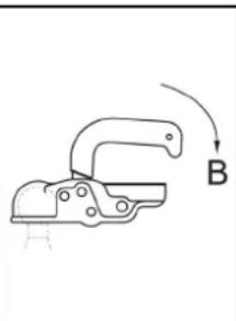
natural_image
Simple line drawing of a mechanical clamp or bracket with a label B, no text or symbols present.natural_image
Technical line drawing of a mechanical assembly with no visible text or symbolstext_image
Technical diagram of an engine with numbered components labeled 1, 2, and 3natural_image
Technical line drawing of a mechanical assembly with two arrows indicating motion or force directions (no text or symbols present)①Graisseur
natural_image
Technical line drawing of a mechanical assembly with two vertical supports and directional arrows indicating movement (no text or symbols)2006/42/CE (+2009/127/CE)
2000/14/CE
2014/30/UE
2014/68/UE (en option)
HD 9/23 GeTr1 + HD 9/23 DeTr1
Mesuré : 105
Garanti : 107
HDS 13/20 DeTr1
Mesuré : 97
Garanti : 100
HDS 13/35 DeTr1 + HDS 9/50 DeTr1
Mesuré : 100
Garanti : 102
HDS 17/20 DeTr1
Mesuré : 100
Garanti : 102
OPTIONAL

H. Jenner
Chairman of the Board of Management

S. Reiser
Manager Regulatory Affairs & Certification
71364 Winnenden (Germany)
text_image
Technical diagram of a truck's internal components with numbered parts, including front and side views with Chinese labels.text_image
Diagram showing a control panel with icons for battery, cleaning tools, and a snowflake symbol, labeled with numbers 1 and 2.text_image
°C °F S P 8.8:8.8 ESM3710-N SET P ✓ EMKOnatural_image
Pure technical line drawing of a mechanical assembly without any text, numbers, or symbolsnatural_image
Pure technical line drawing of industrial piping and valves without any text or symbolsnatural_image
Technical line drawing of a mechanical assembly with no visible text or symbolsnatural_image
Technical line drawing of a mechanical device with an arrow indicating direction (no text or symbols present)natural_image
Technical line drawing of a mechanical assembly with no visible text or symbolstext_image
Technical diagram of a mechanical assembly with numbered parts and detailed cross-sections for identification.
text_image
HDS 13/20 HDS 17/20 17 16 15 13 18 14 13 12 11 HDS 9/50 HDS 13/35 20 19text_image
Technical diagram of a mechanical engine with numbered components labeled 1, 2, and 3natural_image
Technical line drawing of a mechanical assembly with three arrows pointing to specific components (no text or symbols present)natural_image
Technical diagram of a vehicle suspension system with two directional arrows indicating movement or force directions (no text or labels present)HD 9/23 GeTr1 + HD 9/23 DeTr1
Misurato: 105
Garantito: 107
HDS 13/20 DeTr1
Misurato: 97
Garantito: 100
HDS 13/35 DeTr1 + HDS 9/50 DeTr1
Misurato: 100
Garantito: 102
HDS 17/20 DeTr1
Misurato: 100
Garantito: 102
OPTIONAL

H. Jenner
Chairman of the Board of Management

S. Reiser
Manager Regulatory Affairs & Certification
71364 Winnenden (Germany)
Tel.: +49 7195 14-0
Fax: +49 7195 14-2212
Winnenden, 01/01/2023
Dati tecnici
HDS 9/50 DE Tr1 HDS 13/35 DE Tr1 HDS 13/20 DE Tr1 HDS 17/20 DE Tr1
text_image
Technical diagram of a truck's internal components with numbered labels pointing to various partstext_image
°C °F S P 8.8:8.8 ESM3710-N SET P ✓ EMKOnatural_image
Pure technical line drawing of a mechanical or electrical component without any text, numbers, or symbolsnatural_image
Technical line drawing of a mechanical valve assembly (no text or symbols)natural_image
Technical line drawing of a mechanical assembly with no visible text or symbolsnatural_image
Technical line drawing of a mechanical component with an arrow indicating direction (no text or symbols)natural_image
Technical line drawing of a mechanical assembly with no visible text or symbolstext_image
Technical diagram of a mechanical assembly with numbered parts and exploded views, likely for assembly or maintenance purposes.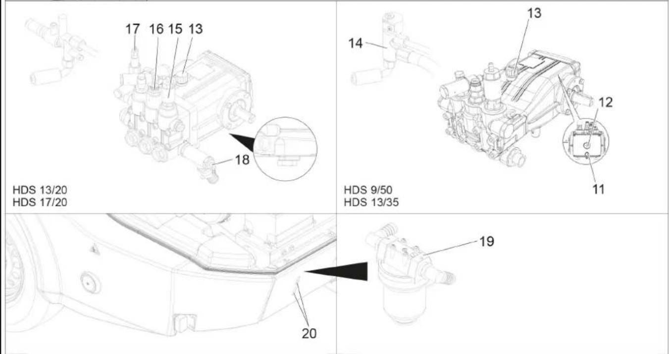
text_image
17 16 15 13 18 HDS 13/20 HDS 17/20 14 13 12 11 HDS 9/50 HDS 13/35 20 19text_image
Technical diagram of an engine with numbered components labeled 1, 2, and 3natural_image
Technical line drawing of a mechanical assembly with three arrows indicating motion or force directions (no text or symbols present)natural_image
Technical line drawing of a mechanical assembly with two directional arrows indicating movement or force directions (no text or symbols present)2006/42/CE (+2009/127/CE)
2000/14/CE
2014/30/UE
HD 9/23 GeTr1 + HD 9/23 DeTr1
Medida: 105
Garantizada: 107
HDS 13/20 DeTr1
Medida: 97
Garantizada: 100
HDS 13/35 DeTr1 + HDS 9/50 DeTr1
Medida: 100
Garantizada: 102
HDS 17/20 DeTr1
Medida: 100
Garantizada: 102
OPTIONAL

H. Jenner
Chairman of the Board of Management

S. Reiser
Manager Regulatory Affairs & Certification
71364 Winnenden (Germany)
Tel.: +49 7195 14-0
Fax: +49 7195 14-2212
Winnenden, 01/01/2023
Datos técnicos
HDS 9/50 DE Tr1 HDS 13/35 DE Tr1 HDS 13/20 DE Tr1 HDS 17/20 DE Tr1
Conexión de agua
Temperatura de entrada (máx.) °C 30 30 30 30
Volumen de entrada (mín.) l/h (l/min) 1000 (16,7) 1500 (25) 1500 (25) 1800 (30)
text_image
Technical diagram of a truck's internal components with numbered parts for identificationtext_image
Labeled diagram of a mechanical or electrical component with numbered parts and control buttons0/OFF = desligado
text_image
ESM3710-N SET P ✓ EMKO 8.8:8.8natural_image
Pure technical line drawing of a mechanical valve assembly without any text, labels, or symbolsnatural_image
Pure technical line drawing of a mechanical valve assembly without any text, labels, or symbolsnatural_image
Technical line drawing of a mechanical assembly with two tool holders (no text or symbols)natural_image
Technical line drawing of a mechanical component with an arrow indicating direction (no text or symbols)natural_image
Technical line drawing of a mechanical assembly with no visible text or symbolstext_image
Technical diagram of a mechanical assembly with numbered parts and an inset view of a component detail.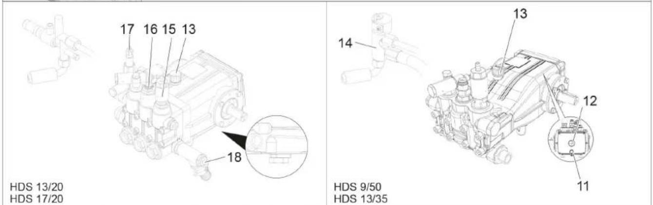
text_image
17 16 15 13 HDS 13/20 HDS 17/20 18 14 13 12 11 HDS 9/50 HDS 13/35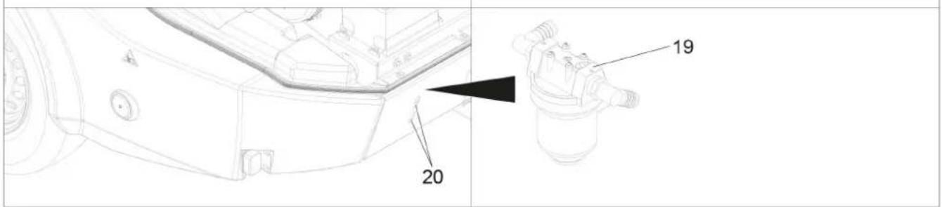
text_image
20 19text_image
Technical diagram of an engine with numbered components labeled 1, 2, and 3natural_image
Technical line drawing of a mechanical assembly with arrows indicating motion or force directions (no text or symbols present)natural_image
Technical line drawing of a mechanical assembly with two directional arrows indicating movement or force directions (no text or symbols present)② Motor desligado (OFF)
2006/42/CE (+2009/127/CE)
2000/14/CE
2014/30/UE
HD 9/23 GeTr1 + HD 9/23 DeTr1
Medido: 105
Garantido: 107
HDS 13/20 DeTr1
Medido: 97
Garantido: 100
HDS 13/35 DeTr1 + HDS 9/50 DeTr1
Medido: 100
Garantido: 102
HDS 17/20 DeTr1
Medido: 100
Garantido: 102
OPTIONAL

H. Jenner
Chairman of the Board of Management
S. Reiser
Manager Regulatory Affairs & Certification
Winnenden, 01/01/2023
Dados técnicos
HDS 9/50 DE Tr1 HDS 13/35 DE Tr1 HDS 13/20 DE Tr1 HDS 17/20 DE Tr1
text_image
Technical diagram of a truck's internal components with numbered labels pointing to various partstext_image
Diagram showing a control panel with icons for fuel, water, brush, and food items, labeled with numbered annotations.text_image
ESM3710-N SET P ✓ SEMKOnatural_image
Pure technical line drawing of a mechanical or architectural component without any text, numbers, or symbolsnatural_image
Pure technical line drawing of a mechanical or electrical component without any text, numbers, or symbolsnatural_image
Technical line drawing of a mechanical assembly with no visible text or symbolsnatural_image
Line drawing of a vehicle's front compartment with an arrow indicating left side (no text or symbols)natural_image
Technical line drawing of a mechanical assembly with no visible text or symbolstext_image
Technical diagram of an engine showing labeled components with numbered parts 1, 2, and 3.natural_image
Technical line drawing of a mechanical assembly with three arrows indicating motion or force directions (no text or symbols present)① Smeernippel
Bandenspanning controleren
natural_image
Technical line drawing of a mechanical assembly with two directional arrows indicating movement or force directions (no text or symbols present)HD 9/23 GeTr1 + HD 9/23 DeTr1
Gemeten: 105
Gegarandeerd: 107
HDS 13/20 DeTr1
Gemeten: 97
Gegarandeerd: 100
HDS 13/35 DeTr1 + HDS 9/50 DeTr1
Gemeten: 100
Gegarandeerd: 102
HDS 17/20 DeTr1
Gemeten: 100
Gegarandeerd: 102
OPTIONAL
Product: ABS stoom HDS 1000
Type: 2.013-093.0

H. Jenner
Chairman of the Board of Management

S. Reiser
Manager Regulatory Affairs & Certification
71364 Winnenden (Germany)
Tel.: +49 7195 14-0
Fax: +49 7195 14-2212
Winnenden, 2023/01/01
Technische gegevens
HDS 9/50 DE Tr1 HDS 13/35 DE Tr1 HDS 13/20 DE Tr1 HDS 17/20 DE Tr1
text_image
Technical diagram of a truck's internal components with numbered labels pointing to various partstext_image
Diagram showing a control panel with icons for fuel, kitchen, cleaning, and food items, labeled with numbered annotations.text_image
ESM3710-N SET P ✓ EMKO 8.8:8.8natural_image
Pure mechanical diagram showing pipe connections without any text, numbers, or symbolsnatural_image
Technical line drawing of a mechanical valve assembly (no text or symbols)natural_image
Technical line drawing of a mechanical assembly with no visible text or symbolsnatural_image
Technical line drawing of a mechanical component with an arrow indicating direction (no text or symbols)natural_image
Two mechanical clamping mechanisms labeled A and B, shown in side-by-side diagrams with no text or symbols beyond labels.natural_image
Technical line drawing of a mechanical assembly with no visible text or symbolstext_image
Technical diagram of an engine with numbered components labeled 1, 2, and 3natural_image
Technical line drawing of a mechanical assembly with arrows indicating motion or force directions (no text or symbols present)
ağlama memesi
natural_image
Technical line drawing of a mechanical assembly with two vertical supports and a central horizontal bar (no text or symbols)HD 9/23 GeTr1 + HD 9/23 DeTr1
Ölçülen: 105
Garanti edilen: 107
HDS 13/20 DeTr1
Ölçülen: 97
Garanti edilen: 100
HDS 13/35 DeTr1 + HDS 9/50 DeTr1
Ölçülen: 100
Garanti edilen: 102
HDS 17/20 DeTr1
Olçülen: 100
Garanti edilen: 102
OPTIONAL
Ürün: ABS buharlı HDS 1000
Tip: 2.013-093.0

H. Jenner
Chairman of the Board of Management

S. Reiser
Manager Regulatory Affairs & Certification
Winnenden, 2023/01/01
Teknik veriler
text_image
Technical diagram of a truck's internal components with numbered parts for identificationtext_image
Diagram showing a control panel with icons for fuel, kitchen, brush, and food items, labeled with numbered annotations.text_image
°C °F S P 8.0:8.0 ESM3710-N SET P ✓ EMKOnatural_image
Pure technical line drawing of a mechanical assembly without any text, numbers, or symbolsnatural_image
Pure technical line drawing of a mechanical or electrical component without any text, numbers, or symbolsnatural_image
Technical line drawing of a mechanical assembly with no visible text or symbolsnatural_image
Technical line drawing of a mechanical component with an arrow indicating direction (no text or symbols)natural_image
Technical line drawing of a mechanical assembly with no visible text or symbolstext_image
Technical diagram of an engine with numbered components labeled 1, 2, and 3①Fästskruvar generator
② Kilrem
③Remspänning ca 7–9 mm
Hänvisning
natural_image
Technical line drawing of a mechanical assembly with three arrows indicating motion or force directions (no text or symbols present)① Smörjnippel
natural_image
Technical line drawing of a vehicle chassis frame with two directional arrows indicating movement or force (no text or symbols present)
H. Jenner
Chairman of the Board of Management

S. Reiser
Manager Regulatory Affairs & Certification
D-71364 Winnenden (Germany)
Tfn: +49 7195 14-0
Fax: +49 7195 14-2212
Winnenden, 01.01.2023
HD 9/23 GeTr1 + HD 9/23 DeTr1
Uppmätt: 105
Garanterad: 107
HDS 13/20 DeTr1
Uppmätt: 97
Garanterad: 100
HDS 13/35 DeTr1 + HDS 9/50 DeTr1
Uppmätt: 100
Garanterad: 102
HDS 17/20 DeTr1
Uppmätt: 100
Garanterad: 102
OPTIONAL
text_image
Technical diagram of a truck's internal components with numbered labels pointing to various partstext_image
ESM3710-N SET P ✓ EMKO 8.8:8.8natural_image
Pure mechanical diagram showing pipe connections without any text, numbers, or symbolsnatural_image
Pure technical line drawing of mechanical components without any text, numbers, or symbolsnatural_image
Technical line drawing of a mechanical assembly with no visible text or symbolsnatural_image
Technical line drawing of a mechanical component with an arrow indicating direction (no text or symbols)natural_image
Technical line drawing of a mechanical assembly with no visible text or symbolstext_image
Technical diagram of an engine with numbered components labeled 1, 2, and 3natural_image
Technical line drawing of a mechanical assembly with two arrows indicating motion or force directions (no text or symbols present)
'oitelunippa
Rengaspaineen tarkastus
natural_image
Technical line drawing of a mechanical assembly with two directional arrows indicating movement or force directions (no text or symbols present)HD 9/23 GeTr1 + HD 9/23 DeTr1
Mitattu: 105
Taattu: 107
HDS 13/20 DeTr1
Mitattu: 97
Taattu: 100
HDS 13/35 DeTr1 + HDS 9/50 DeTr1
Mitattu: 100
Taattu: 102
HDS 17/20 DeTr1
Mitattu: 100
Taattu: 102
OPTIONAL

H. Jenner
Chairman of the Board of Management

S. Reiser
Manager Regulatory Affairs & Certification
71364 Winnenden (Germany)
Puh.: +49 7195 14-0
text_image
Technical diagram of a truck's internal components with numbered labels pointing to various parts① Reflektor (på begge sider)
② Bakre deksel
③Kombinert bremse-/baklys med retningsviser (venstre)
④ Slangegjennomføring ved lukket bakre deksel
⑤Lås bakre deksel
⑥ Nummerskilt med nummerskiltlys
⑦Kombinert bremse-/baklys med retningsviser (høyre)
⑧ Gripehåndtak for frontdeksel (på begge sider)
⑨ Begrensningslys (på begge sider)
⑩Stoppekloss
11Støttehjul
⑫Fangkrok
⑬Pluggforbindelse kjøretøybelysning
14 Bremsekabel
⑮Trekkstang
16 Parkeringsbrems
⑰Koblingsarm
⑱ Holder for pluggforbindelse kjøretøybelysning
19 Veiv til støttehjul
20 Lás frontdeksel
21Frontdeksel
22 Eksosåpning
23Løftering
text_image
°C °F S P 8.8:8.8 ESM3710-N SET P ✓ EMKOnatural_image
Pure technical line drawing of a mechanical assembly without any text, numbers, or symbolsnatural_image
Pure technical line drawing of a mechanical or electrical component without any text, numbers, or symbolsnatural_image
Technical line drawing of a mechanical assembly with no visible text or symbols- Koble høytrykksslangen til på forsyningen for frostvæske.
- Koble vannslangen til på returnen for frostvæske.
- Bland frostvæske i frostvæskebeholderen. Blandingsforhold vann/frostvæske velges ut fra angivelsene fra produsenten av frostvæsken.
- Kontroller frostvæskekonsentrasjonen med en standard frostvæsketester og tilpass ved behov.

natural_image
Technical line drawing of a mechanical component with an arrow indicating direction (no text or symbols)natural_image
Technical line drawing of a mechanical assembly with no visible text or symbols| Symbol Type | kundeservice |
| Brennerservice |
| Motorservice |
| Pumpeservice |
| Høytrykkspistol-service |
Vedlikeholdsintervaller
text_image
Technical diagram of an engine with numbered components labeled 1, 2, and 3① Festeskruer dynamo
②Kilerem
③Reimstramming ca. 7–9 mm
Merknad
natural_image
Technical line drawing of a mechanical assembly with two black arrows pointing to specific components (no text or symbols present)① Smørenippel
natural_image
Technical line drawing of a mechanical assembly with two directional arrows indicating movement or force directions (no text or symbols present)-
Plasser en jekk ved tilsvarende løftepunkt.
-
Løsne hjulskruene.
- Løft apparatet med jekken.
- Skru ut hjulskruene.
- Ta av hjulet.
- Sett på plass reservehjulet.
- Sett på hjulskruene.
- Senk apparatet ved hjelp av jekken.
- Trekk til hjulskruer på kryss.
Tiltrekkingsmoment 110–120 Nm
Merknad
Det er ingen jekk inkludert i leveransen.
Merknad
Bruk en egnet, standard vognløfter.
Tilhenger
Chairman of the Board of Management
S. Reiser
Manager Regulatory Affairs & Certification
71364 Winnenden (Germany)
Tlf.: +49 7195 14-0
Winnenden, 2023/01/01
2006/42/EF (+2009/127/EF)
2000/14/EF
2014/30/EU
2014/68/EU (alternativt)
Anvendte harmoniserte standarder
EN 60335-1
EN 60335-2-79
EN 1829-1
EN 1829-2
EN ISO 12100
EN 13309: 2010
EN 55012: 2007 + A1: 2009
EN 62233: 2008
2000/14/EF: Vedlegg V
Lydeffektnivå dB(A)
HD 9/23 GeTr1 + HD 9/23 DeTr1
Målt: 105
Garantert: 107
HDS 13/20 DeTr1
Målt: 97
Garantert: 100
HDS 13/35 DeTr1 + HDS 9/50 DeTr1
Målt: 100
Garantert: 102
HDS 17/20 DeTr1
Målt: 100
Garantert: 102
OPTIONAL
Produkt: ABS damp HDS 1000
Type: 2.013-093.0
Komponentkategori
||
Samsvarsprosedyrer
Modul H1
Varmespiral
Samsvarsvurderingsmodul H1
Styreblokk
Samsvarsvurderingsmodul H1
Diverse rørledninger
Samsvarsvurdering artikkel 4, avsnitt 3
text_image
Technical diagram of a truck's internal components with numbered labels pointing to various partstext_image
Diagram showing a control panel with icons for food, kitchen, bathroom, and tool, labeled with numbers 1 and 2 pointing to the panel.text_image
ESM3710-N SET P ✓ EMKO 8.8:8.8natural_image
Pure technical line drawing of a mechanical or electrical component without any text, numbers, or symbols- Åbn vandtankens tilløbs- og aftømningshane for at tømme apparatet helt.
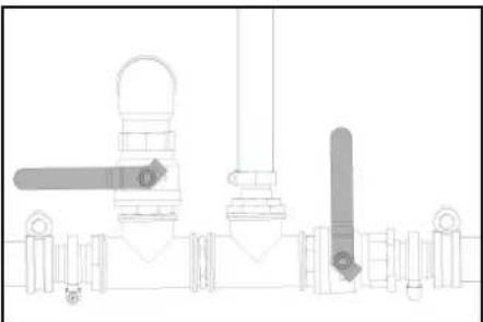
natural_image
Pure technical line drawing of mechanical components without any text, numbers, or symbolsnatural_image
Technical line drawing of a mechanical assembly with no visible text or symbolsnatural_image
Technical line drawing of a mechanical component with an arrow indicating direction (no text or symbols)natural_image
Technical line drawing of a mechanical assembly with no visible text or symbolstext_image
Technical diagram of a mechanical engine with numbered components labeled 1, 2, and 3natural_image
Technical line drawing of a mechanical assembly with three arrows indicating motion or force directions (no text or symbols present)① Smørenipler
natural_image
Technical line drawing of a mechanical assembly with two directional arrows indicating movement or force directions (no text or symbols present)
H. Jenner
Chairman of the Board of Management

S. Reiser
Manager Regulatory Affairs & Certification
71364 Winnenden (Germany)
Tlf.: +49 7195 14-0
Fax: +49 7195 14-2212
Winnenden, 2023/01/01
2006/42/EF (+2009/127/EF)
2000/14/EF
2014/30/EU
2014/68/EU (ekstraudstyr)
HD 9/23 GeTr1 + HD 9/23 DeTr1
Målt: 105
Garanteret: 107
HDS 13/20 DeTr1
Målt: 97
Garanteret: 100
HDS 13/35 DeTr1 + HDS 9/50 DeTr1
Målt: 100
Garanteret: 102
HDS 17/20 DeTr1
Målt: 100
Garanteret: 102
OPTIONAL
Produkt: ABS damp HDS 1000
Type: 2.013-093.0
Kategori af modul
||
Overensstemmelsesvurderingsprocedure
Modul H1
Varmeslange
Overensstemmelsesvurdering modul H1
Styringsblok
Overensstemmelsesvurdering modul H1
Diverse rørledninger
Overensstemmelsesvurdering art. 4, stk. 3
text_image
Technical diagram of a truck's internal components with numbered parts, including dashboard and cargo container parts.23 Tõsteaas
text_image
ESM3710-N SET P ✓ EMKO 8.8:8.8natural_image
Pure technical line drawing of a mechanical valve assembly without any text, labels, or symbolsnatural_image
Pure technical line drawing of a mechanical valve assembly without any text, labels, or symbolsnatural_image
Technical line drawing of a mechanical assembly with no visible text or symbolsnatural_image
Technical line drawing of a mechanical component with an arrow indicating direction (no text or symbols)natural_image
Technical line drawing of a mechanical assembly with no visible text or symbolstext_image
Technical diagram of an engine with numbered components labeled 1, 2, and 3① Generaatori kinnituskruvid
② Kiilrihm
③Rihmapinge u 7-9 mm
Märkus
natural_image
Technical line drawing of a mechanical assembly with three arrows pointing to components (no text or symbols)①Määrdeniplid
Rehvirōhu kontrollimine
natural_image
Technical line drawing of a mechanical assembly with two upward-pointing arrows indicating motion or force directions (no text or symbols present)Toode: Körgsurvepesur
Tüüp: 1.524-xxx
Tüüp: 1.999-380.0
2006/42/EÜ (+2009/127/EÜ)
2000/14/EÜ
2014/30/EL
2014/68/EU (valikuline)
HD 9/23 GeTr1 + HD 9/23 DeTr1
Mōōdetud: 105
Garanteeritud: 107
HDS 13/20 DeTr1
Möödetud: 97
Garanteeritud: 100
HDS 13/35 DeTr1 + HDS 9/50 DeTr1
Möödetud: 100
Garanteeritud: 102
HDS 17/20 DeTr1
Möödetud: 100
Garanteeritud: 102
OPTIONAL
Toode: ABS Dampf HDS 1000
Tüüp: 2.013-093.0

H. Jenner
Chairman of the Board of Management
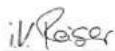
S. Reiser
Manager Regulatory Affairs & Certification
71364 Winnenden (Germany)
Tel: +49 7195 14-0
Winnenden, 2023/01/01
Tehnilised andmed
HDS 9/50 DE Tr1 HDS 13/35 DE Tr1 HDS 13/20 DE Tr1 HDS 17/20 DE Tr1
text_image
Technical diagram of a truck's internal components with numbered labels pointing to various partstext_image
Labeled diagram of a mechanical or electrical component with numbered parts and control buttonstext_image
Diagram showing a control panel with icons for fuel, kitchen, bathroom, and tool, labeled with numbers 1 and 2 pointing to the button.text_image
°C °F S P 8.8:8.8 ESM3710-N SET P ✓ EMKOnatural_image
Architectural line drawing of a building facade with vertical supports and a central tower (no text or symbols)- Atveriet üdens tvertnu ieplüdes värstu un izplüdes värstu, lai ierici pilnibā iztukšotu.
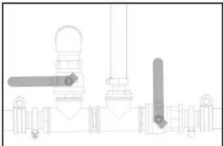
natural_image
Technical line drawing of a mechanical valve assembly (no text or symbols)natural_image
Technical line drawing of a mechanical assembly with no visible text or symbolsnatural_image
Technical line drawing of a mechanical device with an arrow indicating direction (no text or symbols)natural_image
Technical line drawing of a mechanical assembly with no visible text or symbolstext_image
Technical diagram of a mechanical engine with numbered components labeled 1, 2, and 3natural_image
Technical line drawing of a mechanical assembly with arrows indicating motion or force directions (no text or symbols present)
Ellošanas nipelis
natural_image
Technical line drawing of a mechanical assembly with two directional arrows indicating movement or force directions (no text or symbols present)HD 9/23 GeTr1 + HD 9/23 DeTr1
Izmērīts: 105
Nodrošināts: 107
HDS 13/20 DeTr1
Izmērīts: 97
Nodrošināts: 100
HDS 13/35 DeTr1 + HDS 9/50 DeTr1
Izmērīts: 100
Nodrošināts: 102
HDS 17/20 DeTr1
Izmērīts: 100
Nodrošināts: 102
OPTIONAL
Produkts: ABS tvaiks HDS 1000
Tips: 2.013-093.0

H. Jenner
Chairman of the Board of Management

S. Reiser
Manager Regulatory Affairs & Certification
text_image
Technical diagram of a truck's internal components with numbered labels pointing to various partstext_image
Diagram showing a control panel with icons for food, kitchen, bathroom, and tool, labeled with numbers 1 and 2 pointing to the panel.text_image
ESM3710-N SET P ✓ EMKO °C °F S P 8.8:8.8natural_image
Pure technical line drawing of a mechanical or electrical component without any text, numbers, or symbolsnatural_image
Technical line drawing of industrial piping and valves (no text or symbols)natural_image
Technical line drawing of a mechanical assembly with no visible text or symbolsnatural_image
Technical line drawing of a mechanical component with an arrow indicating direction (no text or symbols)natural_image
Technical line drawing of a mechanical assembly with no visible text or symbolstext_image
Technical diagram of a mechanical engine with numbered components labeled 1, 2, and 3natural_image
Technical line drawing of a mechanical assembly with three arrows indicating components (no text or symbols present)①Tepimo jmova
Padangu oro slégio tikrinimas
natural_image
Technical line drawing of a mechanical assembly with two directional arrows indicating movement or force directions (no text or symbols present)HD 9/23 GeTr1 + HD 9/23 DeTr1
Išmatuotas: 105
Garantuojamas: 107
HDS 13/20 DeTr1
Išmatuotas: 97
Garantuojamas: 100
HDS 13/35 DeTr1 + HDS 9/50 DeTr1
Išmatuotas: 100
Garantuojamas: 102
HDS 17/20 DeTr1
Išmatuotas: 100
Garantuojamas: 102
OPTIONAL
Gaminys: ABS Dampf HDS 1000
Tipas: 2.013-093.0

H. Jenner
Chairman of the Board of Management

S. Reiser
Manager Regulatory Affairs & Certification
text_image
Technical diagram of a truck's internal components with numbered parts for identificationtext_image
Technical diagram of a vehicle's internal components with numbered parts and labeled sections in Chinesetext_image
Diagram showing a control panel with icons for fuel, cleaning, and inspection functions, labeled with numbers 1 and 2.natural_image
Technical line drawing of a mechanical component with an arrow indicating direction (no text or symbols)natural_image
Technical line drawing of a mechanical assembly with no visible text or symbolstext_image
Technical diagram of an engine with numbered components labeled 1, 2, and 3natural_image
Technical line drawing of a mechanical assembly with three arrows indicating motion or force directions (no text or symbols present)①Gniazdo smarowe
natural_image
Technical line drawing of a mechanical assembly with two arrows indicating directional components (no text or symbols present)2006/42/WE (+2009/127/WE)
2000/14/WE
2014/30/UE
2014/68/UE (opcja)
HD 9/23 GeTr1 + HD 9/23 DeTr1
Zmierzony: 105
Gwarantowany: 107
HDS 13/20 DeTr1
Zmierzony: 97
Gwarantowany: 100
HDS 13/35 DeTr1 + HDS 9/50 DeTr1
Zmierzony: 100
Gwarantowany: 102
HDS 17/20 DeTr1
Zmierzony: 100
Gwarantowany: 102
OPTIONAL
Produkt: ABS para HDS 1000
Typ: 2.013-093.0

H. Jenner
Chairman of the Board of Management

S. Reiser
Manager Regulatory Affairs & Certification
71364 Winnenden (Germany)
Tel.: +49 7195 14-0
text_image
Technical diagram of a truck's internal components with numbered labels pointing to various partstext_image
ESM3710-N SET P ✓ EMKO °C °F S P 8.8:8.8natural_image
Pure technical line drawing of a mechanical or architectural component without any text, numbers, or symbolsnatural_image
Pure technical line drawing of industrial piping and valves without any text or symbolsnatural_image
Technical line drawing of a mechanical assembly with no visible text or symbolsnatural_image
Technical line drawing of a mechanical component with an arrow indicating direction (no text or symbols)natural_image
Technical line drawing of a mechanical assembly with no visible text or symbolstext_image
Technical diagram of an engine showing labeled components including fan, blades, and shaftsnatural_image
Technical line drawing of a mechanical assembly with two black arrows pointing to specific components (no text or symbols present)①Zsírzógomb
natural_image
Technical line drawing of a mechanical assembly with two directional arrows indicating movement or force directions (no text or symbols present)HD 9/23 GeTr1 + HD 9/23 DeTr1
Mért: 105
Szavatolt: 107
HDS 13/20 DeTr1
Mért: 97
Szavatolt: 100
HDS 13/35 DeTr1 + HDS 9/50 DeTr1
Mért: 100
Szavatolt: 102
HDS 17/20 DeTr1
Mért: 100
Szavatolt: 102
OPTIONAL

H. Jenner
Chairman of the Board of Management

S. Reiser
Manager Regulatory Affairs & Certification
Winnenden, 2023/01/01
Műszaki adatok
HDS 9/50 DE Tr1 HDS 13/35 DE Tr1 HDS 13/20 DE Tr1 HDS 17/20 DE Tr1
Vízcsatlakozás
text_image
Technical diagram of a truck's internal components with numbered labels pointing to various partstext_image
Diagram showing a control panel with icons for fuel, kitchen, food, and tools, labeled with numbers 1 and 2 pointing to a display screen.natural_image
Pure technical line drawing of mechanical components without any text, numbers, or symbolsnatural_image
Pure mechanical diagram showing pipe fittings and valves without any text, numbers, or symbolsnatural_image
Technical line drawing of a mechanical assembly with no visible text or symbolsnatural_image
Technical line drawing of a mechanical component with an arrow indicating direction (no text or symbols)natural_image
Technical line drawing of a mechanical assembly with no visible text or symbolstext_image
Technical diagram of an engine with numbered components labeled 1, 2, and 3natural_image
Technical line drawing of a mechanical assembly with two black arrows pointing to specific components (no text or symbols present)① Maznice
natural_image
Technical line drawing of a mechanical assembly with two directional arrows indicating movement or force directions (no text or symbols present)2006/42/ES (+2009/127/ES)
2000/14/ES
2014/30/EU
2014/68/EU (volitelné)
HD 9/23 GeTr1 + HD 9/23 DeTr1
Naměřeno: 105
Zaručeno: 107
HDS 13/20 DeTr1
Naměřeno: 97
Zaručeno: 100
HDS 13/35 DeTr1 + HDS 9/50 DeTr1
Naměřeno: 100
Zaručeno: 102
HDS 17/20 DeTr1
Naměřeno: 100
Zaručeno: 102
OPTIONAL

H. Jenner
Chairman of the Board of Management

S. Reiser
Manager Regulatory Affairs & Certification
Winnenden, 2023/01/01
Technické údaje
HDS 9/50 DE Tr1 HDS 13/35 DE Tr1 HDS 13/20 DE Tr1 HDS 17/20 DE Tr1
text_image
Technical diagram of a truck's internal components with numbered parts, including front and side views with numbered labels.text_image
ESM3710-N SET P ✓ EMKO 8.8:8.8natural_image
Pure technical line drawing of a mechanical or electrical component without any text, numbers, or symbolsnatural_image
Pure technical line drawing of a mechanical valve assembly without any text or symbolsnatural_image
Technical line drawing of a mechanical assembly with no visible text or symbolsnatural_image
Technical line drawing of a mechanical component with an arrow indicating direction (no text or symbols)natural_image
Technical line drawing of a mechanical assembly with no visible text or symbolstext_image
Technical diagram of a mechanical engine with numbered components labeled 1, 2, and 3natural_image
Technical line drawing of a mechanical assembly with two black arrows pointing to specific components (no text or symbols present)
natural_image
Technical line drawing of a mechanical assembly with two directional arrows indicating movement or force directions (no text or symbols present)-
Nasad'te zdvihák vozidla na príslušný upevnovací bod.
-
Uvolnite skrutky kolesa.
- Prístroj nadvihnite pomocou zdviháka vozidla.
- Vyskrutkujte skrutky kolesa.
- Odoberte koleso.
- Nasadte náhradné koleso.
- Vložte skrutky kolesa.
- Prístroj spustite pomocou zdviháka vozidla.
- Utiahnite krížom skrutky kolesa.
Ut'ahovací moment 110-120 Nm
Upozornenie
2006/42/ES (+2009/127/ES)
2000/14/ES
2014/30/EÚ
2014/68/EÚ (volitel'ne)
HD 9/23 GeTr1 + HD 9/23 DeTr1
Namerané: 105
Zaručené: 107
HDS 13/20 DeTr1
Namerané: 97
Zaručené: 100
HDS 13/35 DeTr1 + HDS 9/50 DeTr1
Namerané: 100
Zaručené: 102
HDS 17/20 DeTr1
Namerané: 100
Zaručené: 102
OPTIONAL
Výrobok: ABS Dampf HDS 1000
Typ: 2.013-093.0

H. Jenner
Chairman of the Board of Management
S. Reiser
Manager Regulatory Affairs & Certification
71364 Winnenden (Germany)
Tel.: +49 7195 14-0
Fax: +49 7195 14-2212
Winnenden, 01.01.2023
Technické údaje
HDS 9/50 DE Tr1 HDS 13/35 DE Tr1 HDS 13/20 DE Tr1 HDS 17/20 DE Tr1
text_image
Technical diagram of a garbage truck with numbered parts for identification and assembly reference.text_image
ESM3710-N SET P ✓ EMKO 8.8:8.8- Temperaturo nastavite s SET in tipko ∧ ∨ ter potrdite s √ (območje nastavitev 85–105 °C).
- Ključno stikalo obrnite v desno, dokler se motor ne zažene.
- Visokotlačno pištolo sprostite, tako da varnostno za- skočko potisnete nazaj.
- Odprite visokotlačno pištolo.
Napotek
natural_image
Pure technical line drawing of a mechanical or electrical component without any text, numbers, or symbolsnatural_image
Pure technical line drawing of industrial piping and valves without any text or symbolsnatural_image
Technical line drawing of a mechanical assembly with no visible text or symbolsnatural_image
Technical line drawing of a mechanical device with an arrow indicating direction (no text or symbols)natural_image
Technical line drawing of a mechanical assembly with no visible text or symbols- Odstranite podložno zagozdo na kolesih in jo vtaknite v držala.
- Sprostite parkirno zavoro.
- Preverite delovanje osvetlitve prikolic (zavorne luči, smernike, zadnje luči, osvetlitev registrske tablice).
- Preverite, ali so v tekalni površini pnevmatik kakšni predmeti.
- Preverite stanje pnevmatik.
- Preverite tlak v pnevmatikah, glejte "Vzdrževalna dela".
text_image
Technical diagram of an engine assembly with numbered components labeled 1, 2, and 3①Pritrditveni vijaki dinama
②Klinasti jermen
③Napetost jermena ca. 7-9 mm
Napotek
natural_image
Technical line drawing of a mechanical assembly with two black arrows pointing to specific components (no text or symbols present)① Mazalka
Preverjanje zračnega tlaka v pnevmatikah
- Napravo postavite na ravno površino.
- Napravo za preverjanje tlaka priključite na ventil pnevmatike.
- Preverite zračni tlak (glejte "Tehnične podatke") in ga po potrebi popravite.
Zamenjava kolesa
△NEVARNOST
natural_image
Technical line drawing of a mechanical assembly with two directional arrows indicating movement or force directions (no text or symbols present)-
Dvigalko namestite na ustrezno nosilno točko.
-
Razrahljajte vijake kolesa.
-
Napravo privzdignite z dvigalko.
- Izvijte vijake kolesa.
- Snemite kolo.
- Namestite rezervno kolo.
- Namestite vijake kolesa.
- Spustite napravo z dvigalko.
- Križno pritegnite vijake kolesa.
Pritezni moment 110-120 Nm
Napotek
V obsegu dobave ni dvigalke vozila.
Napotek
Uporabite primerno dvigalko.
Priklopnik
2006/42/ES (+2009/127/ES)
2000/14/ES
2014/30/EU
HD 9/23 GeTr1 + HD 9/23 DeTr1
Izmerjeno: 105
Zajamčeno: 107
HDS 13/20 DeTr1
Izmerjeno: 97
Zajamčeno: 100
HDS 13/35 DeTr1 + HDS 9/50 DeTr1
Izmerjeno: 100
Zajamčeno: 102
HDS 17/20 DeTr1
Izmerjeno: 100
Zajamčeno: 102
OPTIONAL
Izdelek: Priključni komplet para HDS 1000
Tip: 2.013-093.0
Kategorija sklopa
II
Postopek preverjanja skladnosti
Modul H1
Grelna spirala

H. Jenner
Chairman of the Board of Management

S. Reiser
Manager Regulatory Affairs & Certification
Winnenden, 1. 1. 2023
Tehnični podatki
HDS 9/50 DE Tr1 HDS 13/35 DE Tr1 HDS 13/20 DE Tr1 HDS 17/20 DE Tr1
| Prikluček za vodo | |||||
| Temperatura na dotoku (maks.) °C 30 30 30 30 | |||||
| Količina dotoka (min.) | l/h (l/min) | 1000 (16,7) | 1500 (25) | 1500 (25) | 1800 (30) |
| Tlak na dotoku (maks.) MPa (bar) 0,05-1 (0,5-10) 0,1-1 (1-10) 0,1-1 (1-10) 0,15-1 (1,5-10) | |||||
| Podatki o zmogljivosti naprave | |||||
| Črpalna količina, voda | l/h (l/min) | 500-900 (8,3-15) | 650-1300 (10,8-21,7) | 900-1300 (15-21,7) | 900-1700 (15-28,3) |
| Delovni tlak vode s standardno šobo | MPa (bar) | 15-50 (150-500) | 10-35 (100-350) | 6-20 (60-200) | 6-20 (60-200) |
| Dovoljeni delovni nadtlak (maks.) (varnostni ventil) | MPa (bar) | 64 (640) | 44 (440) | 24 (240) | 24 (240) |
| Črpalna količina pri obratovanju s paro | l/h (l/min) | -- | -- | 460 (7,7) | 460 (7,7) |
| Črpalna količina pri obratovanju s paro Dezinfekcija | l/h (l/min) | -- | -- | WR 10, WR 20: 360 (6)WR 50, WR 100: 460 (7,7) | WR 10, WR 20: 360 (6)WR 50, WR 100: 460 (7,7) |
| Obratovalni tlak pri delovanju s paro tlačno šobo (maks.) | MPa (bar) | -- | -- | 3,2 (32) | 3,2 (32) |
| Št. dela Šoba za paro (velikost šobe) pri parnem čiščenju | -- | -- | 2.113-026.0 (060) | 2.113-026.0 (060) | |
| Št. dela Šoba za paro (velikost šobe) za dezinfekcijo | -- | -- | WR 10, WR 20: 2.113-022.0 (045)WR 50, WR 100: 2.113- 026.0 (060) | WR 10, WR 20: 2.113-022.0 (045)WR 50, WR 100: 2.113- 026.0 (060) | |
| Moč pogonskega motorja | kW | 15,5 | 15 | 9 | 11 |
| Število vrtljajev motorja | 1/min | 3100 | 3300 | 2700 | 3300 |
| Baterija | V/Ah | 12/41 | 12/41 | 12/41 | 12/41 |
| Delovna temperatura tople vode (maks.) | °C | 30-98 | 30-98 | 30-98 | 30-98 |
| Delovna temperatura obratovanja s paro | °C | -- | -- | 155 | 155 |
| Črpalna količina, čistilo | l/h (l/min) | -- | -- | 0-50 (0-0,8) | 0-70 (0-1,2) |
| Moč gorilnika | kW | 65 | 97 | 105 | 105 |
| Poraba goriva (maks) l/h 11,7 15 13,7 | 14,3 | ||||
| Poraba goriva pri obratovanju s hladno vodo | l/h | 5,2 | 5,1 | 3,1 | 3,7 |
| Sila vzvratnega sunka visokotlačne pištole | N | 79 | 96 | 72 | 94 |
| Velikost standardne šobe | 030 | 051 | 075 | 090 | |
| pogonska sredstva, | |||||
| Gorivo | Dizel | Dizel | Dizel | Dizel | |
| Količina olja, vmesno gonilo | I | 0,35 | 0,35 | 0,35 | 0,35 |
| Vrsta olja, vmesno gonilo | SAE90 | SAE90 | SAE90 | SAE90 | |
| Količina olja črpalke | I | 1,2 | 1,2 | 1,3 | 1,3 |
| Vrsta olja črpalke | 15W40 | 15W40 | 15W40 | 15W40 | |
| Količina motornega olja | I | 3,5 | 3,5 | 3,5 | 3,5 |
| Vrsta motornega olja | 15W40 | 15W40 | 15W40 | 15W40 | |
| Mere in mase | |||||
| Dolžina x širina x višina | mm | 3646 x 1747 x 1735 | 3646 x 1747 x 1735 | 3646 x 1747 x 1735 | 3646 x 1747 x 1735 |
| Teža brez goriv | kg | 860-1020 | 860-1020 | 860-1020 | 860-1020 |
| Skupna teža vkij. z gorivi in standardnim priborom | kg | 1440-1600 | 1440-1600 | 1440-1600 | 1440-1600 |
| Dovoljena osna obremenitev | kg | 1600 | 1600 | 1600 | 1600 |
| Dovoljena oporna obremenitev (maks.) | kg | 1100/1600 | 100 | 100 | 100 |
| Dovoljena skupna masa (maks.) | kg | 100 | 1100/1600 | 1100/1600 | 1100/1600 |
| Rezervoar za gorivo | I | 100 | 100 | 100 | 100 |
| Posoda za vodo | I | 500 | 500 | 500 | 500 |
| Hladlini sistem | I | 5 | 5 | 5 | 5 |
| Tekoči mehčalec | I | 1 | 1 | 1 | 1 |
| Zaščitno sredstvo proti zmrzovanju | I | 20 | 20 | 20 | 20 |
| Posoda za čistilo | I | -- | -- | -- | -- |
| Pnevmatike | Homologacija v skladu z ECE R 30, ECE R 54, ECE R 108 ali ECE R 109 in dodatno z ECE R 117 | Homologacija v skladu z ECE R 30, ECE R 54, ECE R 108 ali ECE R 109 in dodatno z ECE R 117 | Homologacija v skladu z ECE R 30, ECE R 54, ECE R 108 ali ECE R 109 in dodatno z ECE R 118 | Homologacija v skladu z ECE R 30, ECE R 54, ECE R 108 ali ECE R 109 in dodatno z ECE R 117 | |
| Dimenzija pnevmatik | 185 R 14 C | 185 R 14 C | 185 R 14 C | 185 R 14 C | |
| Indeks nosilnosti | 104 | 104 | 104 | 104 | |
| Indeks hitrosti | N | N | N | N | |
| Dimenzija koles/oblika platišč | 5,5 J x 14 | 5,5 J x 14 | 5,5 J x 14 | 5,5 J x 14 | |
| Globina platišča | 30 | 30 | 30 | 30 | |
| Tlak v pnevmatikah | MPa (bar) | 0,45 (4,5) | 0,45 (4,5) | 0,45 (4,5) | 0,45 (4,5) |
| Zavorni sistem | Naletna zavora | Naletna zavora | Naletna zavora | Naletna zavora | |
| Ugotovljene vrednosti v skladu s standardom EN 60335-2-79 | |||||
| Raven tlaka hrupa LpA | dB(A) | 82 | 82 | 80 | 82 |
| Negotovost KpA | dB(A) | 3 | 3 | 3 | 3 |
| Raven moči hrupa LWA+ negotovost KWA | dB(A) | 103 | 103 | 100 | 103 |
| Vrednost tresljajev za dlaní/roke - visokotlačna pištola | m/s2 | 4,2 | 4,2 | 3,6 | 3,3 |
| Vrednost tresljajev za dlaní/roke - brizgalna cev | m/s2 | 4,2 | 4,2 | 3,6 | 3,3 |
| Negotovost K | m/s2 | 2,1 | 2,1 | 0,85 | 0,8 |
text_image
Technical diagram of a truck's internal components with numbered labels pointing to various parts① Reflector (pe ambele părti)
②Capotă spate
text_image
°C °F S P 8.8:8.8 ESM3710-N SET P ✓ EMKOnatural_image
Pure technical line drawing of a mechanical assembly without any text, numbers, or symbolsnatural_image
Pure technical line drawing of industrial piping and valves without any text or symbolsnatural_image
Technical line drawing of a mechanical assembly with no visible text or symbolsnatural_image
Technical line drawing of a mechanical component with an arrow indicating direction (no text or symbols)Transport necorespunzator
natural_image
Technical line drawing of a mechanical assembly with no visible text or symbolstext_image
Technical diagram of a mechanical assembly with numbered components labeled 1, 2, and 3natural_image
Technical line drawing of a mechanical assembly with three arrows indicating motion or force directions (no text or symbols present)①Niplu de lubrifiere
natural_image
Technical line drawing of a mechanical assembly with two arrows indicating directional components (no text or symbols present)Directive UE relevante
2006/42/UE (+2009/127/UE)
2000/14/UE
2014/30/UE
2014/68/EU (optional)
Norme armonizate aplicate
EN 60335-1
EN 60335-2-79
EN 1829-1
EN 1829-2
EN ISO 12100
EN 13309: 2010
EN 55012: 2007 + A1: 2009
EN 62233: 2008
HD 9/23 GeTr1 + HD 9/23 DeTr1
Măsurat: 105
Garantat: 107
HDS 13/20 DeTr1
Măsurat: 97
Garantat: 100
HDS 13/35 DeTr1 + HDS 9/50 DeTr1
Măsurat: 100
Garantat: 102
HDS 17/20 DeTr1
Măsurat: 100
Garantat: 102
OPTIONAL
Produs: ABS Dampf HDS 1000
Tip: 2.013-093.0

H. Jenner
Chairman of the Board of Management

S. Reiser
Manager Regulatory Affairs & Certification
71364 Winnenden (Germania)
Tel.: +49 7195 14-0
Fax: +49 7195 14-2212
Winnenden, 2023/01/01
Date tehnice
HDS 9/50 DE Tr1 HDS 13/35 DE Tr1 HDS 13/20 DE Tr1 HDS 17/20 DE Tr1
text_image
Technical diagram of a truck's internal components with numbered labels pointing to various partstext_image
Diagram showing a control panel with icons for food, kitchen, bathroom, and tool, labeled with numbers 1 and 2 pointing to the panel.① Spremnik za gorivo (grafički prikaz)
② Način rada zaštite od smrzavanja
Visokotlačna ručna prskalica
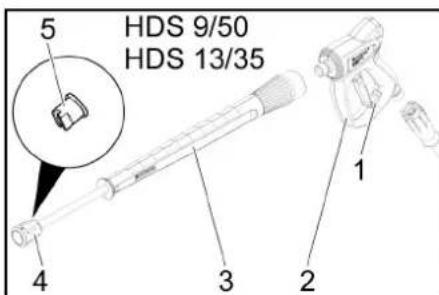
text_image
HDS 9/50 HDS 13/35text_image
ESM3710-N SET P ✓ EMKO 8.8:8.8- Namjestite temperaturu pomoću SET i tipki v te potvrdite s (područje namještanja 85-105 ^ C).
- Okrenite sklopku s ključem udesno dok se motor ne pokrene.
- Uklonite zaštitu visokotlačne ručne prskalice, u tu svrhu gurnite sigurnosni urez prema natrag.
- Otvorite visokotlačnu ručnu prskalicu.
Napomena
Za dostizanje radne temperature potrebno je otprilike 2-4 minute.
7. Provedite uklanjanje korova.
Način rada na pari (čišćenje parom i dezinfekcija)
Samo HDS 13/20, HDS 17/20 (opcija):
Napomena
Za rad u parnom načinu rada obavezan je dodatak za upravljanje broja okretaja (opcija, tvornički: 2.013-086.7, komplet za naknadnu ugradnju: 2.013-014.0)!
△OPASNOST
Opasnost od oparina!
Povećan radni tlak zbog visoke radne temperature. Pri radnim temperaturama iznad 105°C da radni tlak ne smije prelaziti 3,2 MPa (32 bar).
Napomena
Kod čišćenja parom, rad s 2 cijevi za prskanje nije mo- guć.
- Čišćenje parom: Montirajte odgovarajuću mlaznicu za paru na cijev za prskanje (za broj dijela vidi Tehničke podatke).
- Dezinfekcija: Montirajte WR 10, 20, 50 ili 100 na cijev za prskanje i umetnite odgovarajuću mlaznicu za paru (za broj dijela vidi Tehničke podatke).
- Sklopku uredaja postavite način rada „Način rada na pari“.
- Uključite WR-kutiju, stavite sklopku na „ON“.
- Namjestite temperaturu pomoću SET i tipki v te potvrdite s (preporučeno područje namještanja 120-155 ^ C).
- Okrenite sklopku s ključem udesno dok se motor ne pokrene.
- Otvorite poklopac motora i okrenite kotačić na pre- ljevnom ventilu suprotno od kazaljke na satu kako biste manometar podesili na 30 bara.
- Uklonite zaštitu visokotlačne ručne prskalice, u tu svrhu gurnite sigurnosni urez prema natrag.
- Otvorite visokotlačnu ručnu prskalicu.
Napomena
Za dostizanje radne temperature potrebno je otprilike 2-4 minute.
- Provedite čišćenje parom odn. dezinfekciju. Sigurnosne funkcije
1 Indikator WR kutije svijetli crveno: Tlak u sustavu je previsok, plamenik se isključuje, vidi Pomoć u slučaju smetnji.
2 Na zaslonu upravljačko polja pojavljuje se ERROR 5: Tlak u sustavu je prenizak, plamenik se ne pokreće, vidi Pomoć u slučaju smetnji/ERROR 5.
Prekid rada
natural_image
Pure technical line drawing of a mechanical valve assembly without any text, labels, or symbols- Otvorite dovodni ventil spremnika za vodu i ventil za ispuštanje vode kako biste potpuno ispraznili uređaj
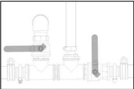
natural_image
Pure technical line drawing of industrial piping and valves without any text or symbolsPokazivač napunjenosti spremnika za vodu se sa- svim spustio.
- Zatvorite dovodni ventil spremnika za vodu i ventil za ispuštanje vode.
- Odvojite visokotlačnu ručnu prskalicu od visokotlačnog crijeva.
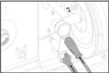
natural_image
Technical line drawing of a mechanical assembly with no visible text or symbolsnatural_image
Technical line drawing of a mechanical component with an arrow indicating direction (no text or symbols)natural_image
Technical line drawing of a mechanical assembly with no visible text or symbolstext_image
Technical diagram of an engine showing labeled components including fan, blades, and shafts① Pričvrsni vijci dinama
② Klinasti remen
③Napetost remena oko 7-9 mm
Napomena
Ako klinasti remen nije dovoljno zategnut, može doći do pregrijavanja motora ili nedovoljnog punjenja akumulatora.
natural_image
Technical line drawing of a mechanical assembly with three arrows indicating motion or force directions (no text or symbols present)natural_image
Technical line drawing of a mechanical assembly with two arrows indicating directional components (no text or symbols present)- Dizalicu namjestite na odgovarajuće prihvatno mjesto.
- Otpustite vijke kotača.
- Podignite uređaj pomoću dizalice za podizanje vozila.
- Odvrnite vijke kotača.
- Skinite kotač.
- Postavite rezervni kotač.
- Postavite vijke kotača.
- Spustite uređaj s dizalicom za podizanje vozila.
- Zategnite vijke kotača u križ.
Pritezni moment 110-120 Nm
Napomena
Dizalica za podizanje motornih vozila nije sadržana u isporuci.
Napomena
Koristite uobičajenu dizalicu za vozila.
Prikolica
HD 9/23 GeTr1 + HD 9/23 DeTr1
Izmjereno: 105
Zajamčeno: 107
HDS 13/20 DeTr1
Izmjereno: 97
Zajamčeno: 100
HDS 13/35 DeTr1 + HDS 9/50 DeTr1
Izmjereno: 100
Zajamčeno: 102
HDS 17/20 DeTr1
Izmjereno: 100
Zajamčeno: 102
OPTIONAL
Proizvod: ABS Dampf HDS 1000
Tip: 2.013-093.0
Kategorija sklopa

H. Jenner
Chairman of the Board of Management

S. Reiser
Manager Regulatory Affairs & Certification
Opunomoćenik za dokumentaciju:
S. Reiser
Alfred Kärcher SE & Co. KG
Alfred-Kärcher-Str. 28 - 40
71364 Winnenden (Njemačka)
Tel.: +49 7195 14-0
Telefaks: +49 7195 14-2212
Winnenden, 01.01.2023.
Tehnički podaci
HDS 9/50 DE Tr1 HDS 13/35 DE Tr1 HDS 13/20 DE Tr1 HDS 17/20 DE Tr1
| Priklučak za vodu | |||||
| Temperatura dovodne vode (maks.) °C 30 30 30 30 | |||||
| Količina dovodne vode (min.) | l/h (l/min) | 1000 (16,7) | 1500 (25) | 1500 (25) | 1800 (30) |
| Dovodni tlak (maks.) MPa (bar) 0,05-1 (0,5-10) 0,1-1 (1-10) 0,1-1 (1-10) 0,15-1 (1,5-10) | |||||
| Podaci o snazi uređaja | |||||
| Protočna količina, voda | l/h (l/min) | 500-900 (8,3-15) | 650-1300 (10,8-21,7) | 900-1300 (15-21,7) | 900-1700 (15-28,3) |
| Radni tlak vode sa standardnom mlaznicom | MPa (bar) | 15-50 (150-500) | 10-35 (100-350) | 6-20 (60-200) | 6-20 (60-200) |
| Sigurnosni ventil za prekomjerni radni tlak (maksimum) | MPa (bar) | 64 (640) | 44 (440) | 24 (240) | 24 (240) |
| Protočna količina, rad s parom | l/h (l/min) | -- | -- | 460 (7,7) | 460 (7,7) |
| Protok pare, dezinfekcija | l/h (l/min) | -- | -- | WR 10, WR 20: 360 (6)WR 50, WR 100: 460 (7,7) | WR 10, WR 20: 360 (6)WR 50, WR 100: 460 (7,7) |
| Radni tlak, rad s parom i parnom mlaznicom (maks.) | MPa (bar) | -- | -- | 3,2 (32) | 3,2 (32) |
| Broj dijela Mlaznica za paru (veličina mlaznice) za čišćenje parom | -- | -- | 2.113-026.0 (060) | 2.113-026.0 (060) | |
| Broj dijela Mlaznica za paru (veličina mlaznice) za dezinfekciju | -- | -- | WR 10, WR 20: 2.113-022.0 (045)WR 50, WR 100: 2.113- 026.0 (060) | WR 10, WR 20: 2.113-022.0 (045)WR 50, WR 100: 2.113- 026.0 (060) | |
| Snaga pogonskog motora | kW | 15,5 | 15 | 9 | 11 |
| Broj okretaja motora | 1/min | 3100 | 3300 | 2700 | 3300 |
| Baterija | V/Ah | 12/41 | 12/41 | 12/41 | 12/41 |
| Radna temperatura tople vode (maksimalna) | °C | 30-98 | 30-98 | 30-98 | 30-98 |
| Radna temperatura rada s parom | °C | -- | -- | 155 | 155 |
| Protočna količina, sredstvo za čišćenje | l/h (l/min) | -- | -- | 0-50 (0-0,8) | 0-70 (0-1,2) |
| Snaga plamenika | kW | 65 97 105 | 105 | ||
| Potrošnja goriva (maks.) | l/h | 11,7 | 15 | 13,7 | 14,3 |
| Potrošnja goriva prilikom rada s hladnom vodom | l/h | 5,2 | 5,1 | 3,1 | 3,7 |
| Povratna udarna sila visokotlačne ručne prskalice | N | 79 | 96 | 72 | 94 |
| Veličina standardne sapnice | 030 | 051 | 075 | 090 | |
| pogonske tvari, | |||||
| Gorivo | Dizel | Dizel | Dizel | Dizel | |
| Količina ulja, međuprijenosnik | I | 0,35 | 0,35 | 0,35 | 0,35 |
| Vrsta ulja, međuprijenosnik | SAE90 | SAE90 | SAE90 | SAE90 | |
| Količina ulja pumpe | I | 1,2 | 1,2 | 1,3 | 1,3 |
| Crpka za vrstu ulja | 15W40 | 15W40 | 15W40 | 15W40 | |
| Količina motornog ulja | I | 3,5 | 3,5 | 3,5 | 3,5 |
| Vrsta motornog ulja | 15W40 | 15W40 | 15W40 | 15W40 | |
| Dimenzije I težine | |||||
| Duljina x širina x visina | mm | 3646 x 1747 x 1735 | 3646 x 1747 x 1735 | 3646 x 1747 x 1735 | 3646 x 1747 x 1735 |
| Težina bez radnih medija | kg | 860-1020 | 860-1020 | 860-1020 | 860-1020 |
| Ukupna težina uklj. radni mediji i standardni pribor | kg | 1440-1600 | 1440-1600 | 1440-1600 | 1440-1600 |
| Dopušteno osovinsko opterećenje | kg | 1600 | 1600 | 1600 | 1600 |
| Dopušteno okomito opterećenje (maks.) | kg | 1100/1600 | 100 | 100 | 100 |
| Dopuštena ukupna težina (maks.) | kg | 100 | 1100/1600 | 1100/1600 | 1100/1600 |
| Spremnik za gorivo | I | 100 | 100 | 100 | 100 |
| Spremnik za vodu | I | 500 | 500 | 500 | 500 |
| Sustav hlađenja | I | 5 | 5 | 5 | 5 |
| Tekući omekšivač | I | 1 | 1 | 1 | 1 |
| Antifriz | I | 20 20 20 20 | |||
| Spremnik sredstva za čišćenje | I | -- | -- | -- | -- |
| Gume | Odobrenje tipa prema ECE R 30, ECE R 54, ECE R 108 ili ECE R 109 i dodatno ECE R 117 | Odobrenje tipa prema ECE R 30, ECE R 54, ECE R 108 ili ECE R 109 i dodatno ECE R 117 | Odobrenje tipa prema ECE R 30, ECE R 54, ECE R 108 ili ECE R 109 i dodatno ECE R 117 | Odobrenje tipa prema ECE R 30, ECE R 54, ECE R 108 ili ECE R 109 i dodatno ECE R 117 | |
| Veličina guma | 185 R 14 C | 185 R 14 C | 185 R 14 C | 185 R 14 C | |
| Indeks nosivosti | 104 | 104 | 104 | 104 | |
| Indeks brzine | N | N | N | N | |
| Veličina kotača / oblik naplatka | 5,5 J x 14 | 5,5 J x 14 | 5,5 J x 14 | 5,5 J x 14 | |
| Offset | 30 30 30 30 | ||||
| Tlak zraka u gumama | MPa (bar) 0,45 (4,5) 0,45 (4,5) 0,45 (4,5) 0,45 (4,5) | ||||
| Kočni sustav | Naletna kočnica | Naletna kočnica | Naletna kočnica | Naletna kočnica | |
| Vrijednosti utvrđene prema EN 60335-2-79 | |||||
| Razina zvučnog tlaka LpA | dB(A) | 82 | 82 | 80 | 82 |
| Nesigurnost KpA | dB(A) | 3 | 3 | 3 | 3 |
| Razina zvučne snage LwA + Nesigurnost KwA | dB(A) | 103 | 103 | 100 | 103 |
| Vrijednost vibracije šaka-ruka visokotlačne ručne prskalice | m/s2 | 4,2 | 4,2 | 3,6 | 3,3 |
| Vrijednost vibracije šaka-ruka cijevi za prskanje | m/s2 | 4,2 | 4,2 | 3,6 | 3,3 |
| Nesigurnost K | m/s2 | 2,1 | 2,1 | 0,85 | 0,8 |
text_image
Technical diagram of a truck's internal components with numbered labels pointing to various parts① Reflektor (obostrano)
②Zadnji poklopac
③ Kombinovano kočiono/zadnje svetlo sa pokazivačem pravca (levo)
④Provodnica creva kod zatvorenog zadnjeg poklopca
⑤ Zaključavanje zadnjeg poklopca
⑥Registarska oznaka sa osvetljenjem registarske tablice
⑦ Kombinovano kočiono/zadnje svetlo sa pokazivačem pravca (desno)
⑧ Udubljenje za držanje na prednjem poklopcu (obostrano)
⑨Granično svetlo (obostrano)
10 Podložni klin
⑪ Potporni točak
12 Kuka za hvatanje
⑬ Utični spoj osvetljenja vozila
⑭Sajla za osiguranje prikolice
⑮Vučna ruda
⑯Poziciona kočnica
⑰Poluga spojnice
⑱ Držač za utični spoj osvetljenja vozila
⑲ Obrtna ručka potpornog točka
⑳ Zaključavanje prednjeg poklopca
②1Prednji poklopac
22 Izduvni otvor
⑳Ušica za podizanje
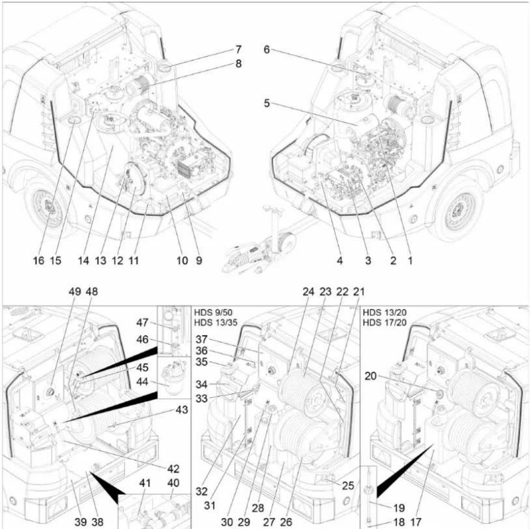
① Dizel-motor
② Međuprenosnik
③Pumpa visokog pritiska
④ Sigurnosni blok gorionika
⑤ Auspuh
⑥ Ekspanzioni sud vode za hlađenje motora
⑦ Otvor za održavanje rezervoara za vodu (levo)
⑧Filteri za vazduh
⑨ Natpisna pločica
10Baterija
⑪Br. voznog postolja
⑫Ventilator gorionika
⑬Pumpa za gorivo
14 Protočni grejač
⑮Transformer za paljenje
⑯Otvor za održavanje rezervoara za vodu (desno)
17 Rezervoar za deterdžent
⑱ Filter na usisnom crevu sredstva za čišćenje
⑲ Usisno crevo sredstva za čiščenje sa senzorom nivoa
20 Ventila za doziranje deterdženta
⑳ Odeljak za odlaganje ručne prskalice
22 Odeljak za odlaganje cevi za prskanje
23 Visokopritisno crevo
24Doboš za namotavanje visokopritisnog creva
25 Prekidač za hitno zaustavljanje
(26) Doboš za namotavanje niskopritisnog creva
27 Posuda za omekšivač
28 Posuda sredstva za zaštitu od mraza
⑲Nastavak za punjenje rezervoara goriva sa rešetkom
③0 Zaštita od smrzavanja kuglastog ventila
③1)Prikaz nivoa punjenja rezervoara za vodu
③2Posuda sa plovkom
③3 Upravljanje brojem obrtaja
③4 Otvor za punjenje posude sa plovkom sa poklopcem/leptirastim zavrtnjem
③5 Otvor za punjenje omekšivača
36) Kuglasti ventil, prebacivanje povratnog voda
37Razvodna kutija
③8Pokrivni lim (desno)
39Pokrivni lim (levo)
④0Ulazna slavina rezervoara za vodu
41Ispusna slavina
42 Crevo za zaštitu od smrzavanja
④3Crevo za vodu
④4 Filter na ulazu vode
45Manometar
④6Dovod zaštite od mraza odn. položaj za parkiranje za GEKA priključak niskog pritiska
④7Povratni vod zaštite od mraza odn. položaj za parkiranje za priključak visokog pritiska
④8 Zatvarač rezervoara za gorivo
④9Komandno polje
Komandno polje
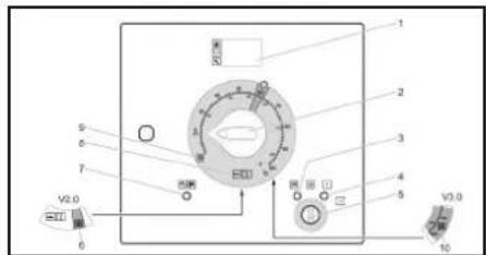
text_image
1 2 3 4 5 6 7 8 9 V2.0 V3.00/OFF = Isključeno
①Ekran
② Prekidač uređaja
③ Indikator predzagrevanja (crvena)
④Indikator spremnosti za rad (crvena)
⑤ Prekidač sa ključem
⑥Režim rada za uklanjanje korova V2.0 (opcija kod HDS 13/20, HDS 17/20)
⑦ Indikator prednjeg poklopca/hitnog zaustavljanja (crvena)
⑧ Način rada hladna/topla voda (0-100°C)
⑨Način rada zaštite od mraza
⑩ Način rada za uklanjanje korova V3.0 & V5.0 odn. način rada Režim rada na paru (opciono kod HDS 13/20, HDS 17/20)
Dokumentacija sa dozvolama
Dokumentacija sa dozvolama za uređaj se nalazi u E-ormanu uređaja. Orman je zatvoren prilikom transporta.
text_image
°C °F S P 8.8:8.8 ESM3710-N SET P ✓ EMKO- Podesite temperaturu preko opcije SET i tastera ∧v i potvrdite sa √ (opseg podešavanja 85-105 °C).
- Okrenite prekidač sa ključem u desnu stranu sve dok motor ne počne da radi.
- Otkočite visokopritisnu ručnu prskalicu guranjem sigurnosnog ureza unazad.
- Otvorite visokopritisnu ručnu prskalicu.
Napomena
To traje 2–4 minuta, sve dok se ne postigne radna temperatura.
7. Izvršite uklanjanje korova.
Režim rada sa parom (čišćenje parom i dezinfekcija)
Samo HDS 13/20, HDS 17/20 (opcija):
Napomena
Za rad u režimu pare nužno je neophodan dodatak za upravljanje brojem obrlaja (opcija, fabrički: 2.013-086.7, komplet za dogradnju: 2.013-014.0)!
△OPASNOST
Opasnost od opekotina!
Povećan radni pritisak zbog visoke radne temperature. Obratite pažnju da na radnim temperaturama iznad 105°C ne sme da se prekorači radni pritisak od 3,2 MPa (32 bar).
Napomena
Kod režima rada sa parom, nije moguć rad sa 2 cevi za prskanje.
- Čišćenje parom: Postavite odgovarajuću mlaznicu za paru na cev za prskanje (br. dela pogledati u tehničkim podacima).
- Dezinfekcija: Postavite WR 10, 20, 50 ili 100 na cev za prskanje i koristite odgovarajuću mlaznicu za paru (br. dela pogledati u tehničkim podacima).
- Podesite prekidač uređaja na način rada „Režim rada sa parom“.
- Uključite WR-Box, prekidač postavite na „ON“.
- Podesite temperaturu preko opcije SET i tastera v i potvrdite sa (preporučeni opseg podešavanja 120-155 ^ C).
-
Okrenite prekidač sa ključem u desnu stranu sve dok motor ne počne da radi.
-
Otvorite poklopac motora i ručni točkić na prelivnom ventilu podesite u smeru suprotnom od kazaljki na satu iza manometra na 30 bar.
- Otkočite visokopritisnu ručnu prskalicu guranjem sigurnosnog ureza unazad.
- Otvorite visokopritisnu ručnu prskalicu.
Napomena
Potrebno je oko 2-4 minuta dok se ne dostigne radna temperatura.
natural_image
Pure technical line drawing of a mechanical or electrical component without any text, numbers, or symbolsnatural_image
Pure technical line drawing of industrial piping and valves without any text or symbolsIndikator nivoa punjenja rezervoara za vodu potpuno opada.
- Zatvoriti ulaznu slavinu rezervoara za vodu i ispusnu slavinu.
- Visokopritisnu prskalicu odvojite od visokopritisnog creva.
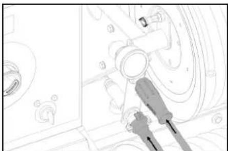
natural_image
Technical line drawing of a mechanical assembly with no visible text or symbols- Priključite visokopritisno crevo na dovod sredstva za zaštitu od mraza.
- Priključite crevo za vodu na povratni vod sredstva za zaštitu od mraza.
- Stavite tečnost za zaštitu od mraza u posudu sredstva za zaštitu od mraza. Izaberite odnos vode/sredstva za zaštitu od mraza prema podacima proizvođača sredstva za zaštitu od mraza.
- Proverite koncentraciju sredstva za zaštitu od mraza pomoću komercijalno dostupnih testera za zaštitu od mraza i podesite po potrebi.
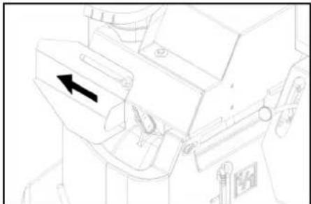
natural_image
Technical line drawing of a mechanical component with an arrow indicating direction (no text or symbols)-
Otvorite otvor za punjenje posude sa plovkom. U tu svrhu, otpustite leptirasti zavrtanj i gurnite poklopac u levu stranu.
-
Napunite 20 litara sredstva za zaštitu od mraza u posudu sa plovkom i otvor za punjenje.
- Polugu za aktiviranje zaštite kuglastog ventila od mraza postavite uspravno.
- Polugu za aktiviranje prebacivanja povratnog voda kuglastog ventila podesite paralelno u odnosu na smer kretanja (20L).
-
Samo kod hladnog motora: Okrenite prekidač sa ključem u levu stranu za predzagrevanje motora i zadržite sve dok se ne isključi indikator predzagrevanja.
-
Prekidač sa ključem okrenite u položaj „I“. Sveti indikator spremnosti za rad. Uključuje se upravljački napon, a displej prikazuje radno stanje „Zaštita od mraza“.
-
Okrenite prekidač sa ključem u desnu stranu sve dok motor ne počne da radi. Tečnost za zaštitu od mraza se pumpa u cirkulaciji kroz uređaj.
-
Preostalu vodu odvedite u posudu sredstva za zaštitu od mraza preko creva sredstva za zaštitu od mraza.
-
Kada sredstvo za zaštitu od mraza počne da ističe na crevu sredstva za zaštitu od mraza, postavite horizontalno polugu za aktiviranje zaštite kuglastog ventila od mraza i sačekajte 5 sekundi.
-
Isključite motor.
-
Prekidač uređaja podesite na „0/OFF“ (gorionik isključen).
Pumpanje sredstva za zaštitu od mraza iz visokopritisnog sistema
Napomena
Pre rada, tečnost za zaštitu od mraza mora da se ispumpa iz visokopritisnog sistema nazad u posudu sredstva za zaštitu od mraza.
-
Polugu za aktiviranje zaštite kuglastog ventila od mraza postavite uspravno.
-
Priključite visokopritisno crevo na dovod sredstva za zaštitu od mraza.
-
Priključite crevo za vodu na povratni vod sredstva za zaštitu od mraza.
-
Otvorite otvor za punjenje posude sa plovkom. U tu svrhu, otpustile leptirasti zavrtanj i gurnite poklopac u levu stranu.
-
Napunite 20 litara sveže vode u posudu sa plovkom i zatvorite otvor za punjenje.
-
Podesite prekidač uređaja na način rada „Zaštita od mraza“.
-
Samo kod hladnog motora: Okrenite prekidač sa ključem u levu stranu za predzagrevanje motora i zadržite sve dok se ne isključi indikator predzagrevanja.
-
Prekidač sa ključem okrenite u položaj „l“. Sveti indikator spremnosti za rad. Uključuje se upravljački napon, a displej prikazuje radno stanje „Zaštita od mraza“.
-
Okrenite prekidač sa ključem u desnu stranu sve dok motor ne počne da radi. Tečnost za zaštitu od mraza se, zajedno sa svežom vodom, transportuje iz posude sa plovkom u posudu sredstva za zaštitu od mraza.
-
Ispiranje vršiti u trajanju od oko 2 minuta, sve dok se posuda sredstva za zaštitu od mraza ne napuni.
-
Isključite motor.
-
Prekidač uređaja podesite na „0/OFF“ (gorionik isključen).
Transport
△OPREZ
Opasnost od povreda i oštećenja!
Nestručan transport
natural_image
Technical line drawing of a mechanical assembly with no visible text or symbols-
Uklonite podložne klinove na točkovima i stavite ih u držače.
-
Otpustite ručnu kočnicu.
-
Proverite funkciju osvetljenja prikolice (svetla kočnice, pokazivači pravca, zadnja svetla, svetla registarske tablice).
-
Proverite da li na radnoj površini guma ima pregaženih predmeta.
-
Proverite stanje guma
-
Proverite pritisak vazduha u gumama, pogledati „Radovi na održavanju“.
Napomena: Obratite pažnju na lokalna ograničenja brzine za vozilo sa prikolicom i poštujte ih.
text_image
Technical diagram of a mechanical engine with numbered components labeled 1, 2, and 3① Zavrtnji za pričvršćenje alternatora
② Klinasti remen
③Zategnutost remena oko 7-9 mm
Napomena
Ako klinasti remen nije dovoljno zategnut, to može da dovede do pregrevanja motora ili do nedovoljnog punjenja baterije.
- isključite motor i izvadite ključ na prekidaču sa ključem.
- Za proveru zatezanja klinastog remena, palcem pritisnite remen između remenica.
Napomena
Klinasti remen treba da može da se pritisne oko 7-9 mm.
Napomena
Principijelno treba zameniti oštećene klinaste remenove.
natural_image
Technical line drawing of a mechanical assembly with three arrows indicating components (no text or symbols present)natural_image
Technical line drawing of a mechanical assembly with two directional arrows indicating movement or force directions (no text or symbols present)-
Postavite dizalicu za podizanje vozila na odgovarajuću prihvatnu tačku.
-
Olabavite zavrtnje na točkovima.
- Podignite uređaj dizalicom za podizanje vozila.
- Odvijte zavrtnje na točkovima.
- Skinite točak.
- Postavite rezervni točak.
- Postavite zavrtnje točka.
- Spustite uređaj dizalicom za podizanje vozila.
- Ćvrsto pritegnite unakrsno zavrtnje točka.
Obrtni momenat pritezanja 110-120 Nm
Napomena
Dizalica za podizanje vozila nije sadržana u obimu isporuke.
Napomena
Koristite odgovarajuću dizalicu za podizanje vozila koja se nalazi u prodaji.
Prikolica
- Ovlašćena specijalizovana radionica treba u redovnim intervalima da vrši proveru kočionog sistema i voznog mehanizma.
Pomoć u slučaju smetnji
△OPASNOST
Nenamerno pokrenut uredaj
HD 9/23 GeTr1 + HD 9/23 DeTr1
Izmereno: 105
Garantovano: 107
HDS 13/20 DeTr1
Izmereno: 97
Garantovano: 100
HDS 13/35 DeTr1 + HDS 9/50 DeTr1
Izmereno: 100
Garantovano: 102
HDS 17/20 DeTr1
Izmereno: 100
Garantovano: 102
OPTIONAL
Proizvod: ABS parni HDS 1000
Tip: 2.013-093.0
Kategorija sklopa

H. Jenner
Chairman of the Board of Management

S. Reiser
Manager Regulatory Affairs & Certification
Lice ovlašćeno za dokumentaciju:
S. Reiser
Alfred Kärcher SE & Co. KG
Alfred-Kärcher-Str. 28 - 40
71364 Winnenden (Germany)
Tel.: +49 7195 14-0
Winnenden, 2023/01/01
Tehnički podaci
HDS 9/50 DE Tr1 HDS 13/35 DE Tr1 HDS 13/20 DE Tr1 HDS 17/20 DE Tr1
| Priključak za vodu | |||||
| Dovodna temperatura (maks.) °C 30 30 30 30 | |||||
| Dovodna količina (min.) | l/h (l/min) | 1000 (16,7) | 1500 (25) | 1500 (25) | 1800 (30) |
| Dovodni pritisak (maks.) | MPa (bar) | 0,05-1 (0,5-10) | 0,1-1 (1-10) | 0,1-1 (1-10) | 0,15-1 (1,5-10) |
| Podaci o snazi uređaja | |||||
| Protočna količina, voda | l/h (l/min) | 500-900 (8,3-15) | 650-1300 (10,8-21,7) | 900-1300 (15-21,7) | 900-1700 (15-28,3) |
| Radni pritisak vode sa standardnom mlaznicom | MPa (bar) | 15-50 (150-500) | 10-35 (100-350) | 6-20 (60-200) | 6-20 (60-200) |
| Prekoračenje radnog pritiska na sigurnosnom ventilu (maksimalno) | MPa (bar) | 64 (640) | 44 (440) | 24 (240) | 24 (240) |
| Protočna količina pri radu s parom | l/h (l/min) | -- | -- | 460 (7,7) | 460 (7,7) |
| Protočna količina pri radu s parom, dezinfekcija | l/h (l/min) | -- | -- | WR 10, WR 20: 360 (6)WR 50, WR 100: 460 (7,7) | WR 10, WR 20: 360 (6)WR 50, WR 100: 460 (7,7) |
| Radni pritisak pri radu s parom sa mlaznicom za paru (maks.) | MPa (bar) | -- | -- | 3,2 (32) | 3,2 (32) |
| Br. dela Mlaznica za paru (veličina mlaznice) za čišćenje parom | -- | -- | 2.113-026.0 (060) | 2.113-026.0 (060) | |
| Br. dela Mlaznica za paru (veličina mlaznice) za dezinfekciju | -- | -- | WR 10, WR 20: 2.113-022.0 (045)WR 50, WR 100: 2.113- 026.0 (060) | WR 10, WR 20: 2.113-022.0 (045)WR 50, WR 100: 2.113- 026.0 (060) | |
| Snaga pogonskog motora | kW | 15,5 | 15 | 9 | 11 |
| Broj obrtaja motora | 1/min | 3100 | 3300 | 2700 | 3300 |
| Baterija | V/Ah | 12/41 | 12/41 | 12/41 | 12/41 |
| Radna temperatura tople vode (maksimalna) | °C | 30-98 | 30-98 | 30-98 | 30-98 |
| Radna temperatura pri radu s parom | °C | -- | -- | 155 | 155 |
| Protočna količina, sredstvo za čišćenje | l/h (l/min) | -- | -- | 0-50 (0-0,8) | 0-70 (0-1,2) |
| Snaga gorionika | kW | 65 97 105 | 105 | ||
| Potrošnja goriva (maks.) | l/h | 11,7 | 15 | 13,7 | 14,3 |
| Potrošnja goriva kod režima rada sa hladnom vodom | l/h | 5,2 | 5,1 | 3,1 | 3,7 |
| Povratna udarna sila visokopritisne ručne prskalice | N | 79 | 96 | 72 | 94 |
| Veličina mlaznice za standardnu mlaznicu | 030 | 051 | 075 | 090 | |
| Operativni materijali | |||||
| Gorivo | Dizel | Dizel | Dizel | Dizel | |
| Količina ulja za međuprenosnik | I | 0,35 | 0,35 | 0,35 | 0,35 |
| Vrsta ulja za međuprenosnik | SAE90 | SAE90 | SAE90 | SAE90 | |
| Količina ulja pumpe | I | 1,2 | 1,2 | 1,3 | 1,3 |
| Vrsta ulja za pumpu | 15W40 | 15W40 | 15W40 | 15W40 | |
| Količina motornog ulja | I | 3,5 | 3,5 | 3,5 | 3,5 |
| Vrsta motornog ulja | 15W40 | 15W40 | 15W40 | 15W40 | |
| Dimenzije i težine | |||||
| Dužina x širina x visina | mm | 3646 x 1747 x 1735 | 3646 x 1747 x 1735 | 3646 x 1747 x 1735 | 3646 x 1747 x 1735 |
| Težina bez pogonskih materijala | kg | 860-1020 | 860-1020 | 860-1020 | 860-1020 |
| Ukupna težina uklj. pogonske materijale i standardni pribor | kg | 1440-1600 | 1440-1600 | 1440-1600 | 1440-1600 |
| Dozvoljeno osovinsko opterećenje | kg | 1600 | 1600 | 1600 | 1600 |
| Dozvoljeno potporno opterećenje (maks.) | kg | 1100/1600 | 100 | 100 | 100 |
| Dozvoljena ukupna težina (maks.) | kg | 100 | 1100/1600 | 1100/1600 | 1100/1600 |
| Rezervoar za gorivo | I | 100 | 100 | 100 | 100 |
| Rezervoar za vodu | I | 500 | 500 | 500 | 500 |
| Rashladni sistem | I | 5 | 5 | 5 | 5 |
| Omekšivač | I | 1 | 1 | 1 | 1 |
| Sredstvo za zaštitu od smrzavanja | I | 20 20 20 20 | |||
| Rezervoar za deterdžent | I | -- | -- | -- | -- |
| Gume | Odobrenje za konstrukciju prema ECE R 30, ECE R 54, ECE R 108 ili ECE R 109 i dodatno ECE R 117 | Odobrenje za konstrukciju prema ECE R 30, ECE R 54, ECE R 108 ili ECE R 109 i dodatno ECE R 117 | Odobrenje za konstrukciju prema ECE R 30, ECE R 54, ECE R 108 ili ECE R 109 i dodatno ECER 117 | Odobrenje za konstrukciju prema ECE R 30, ECE R 54, ECE R 108 ili ECE R 109 i dodatno ECE R 117 | |
| Veličina pneumatika | 185 R 14 C | 185 R 14 C | 185 R 14 C | 185 R 14 C | |
| Indeks nosivosti | 104 | 104 | 104 | 104 | |
| Indeks brzine | N | N | N | N | |
| Veličina točka/oblik felne | 5,5 J x 14 | 5,5 J x 14 | 5,5 J x 14 | 5,5 J x 14 | |
| Dubina otiska | 30 30 30 30 | ||||
| Vazdušni pritisak u pneumaticima | MPa (bar) | 0,45 (4,5) | 0,45 (4,5) | 0,45 (4,5) | 0,45 (4,5) |
| Kočioni sistem | Inercijska kočnica | Inercijska kočnica | Inercijska kočnica | Inercijska kočnica | |
| Utvrđene vrednosti prema EN 60335-2-79 | |||||
| Nivo zvučnog pritiska L_pA | dB(A) | 82 | 82 | 80 | 82 |
| Nepouzdanost K_pA | dB(A) | 3 | 3 | 3 | 3 |
| Nivo zvučne snage L_WA + nepouzdanost K_WA | dB(A) | 103 | 103 | 100 | 103 |
| Vrednost vibracije na šaci-rući od visokopritisne ručne prskalice | m/s^2 | 4,2 | 4,2 | 3,6 | 3,3 |
| Vrednost vibracije na šaci-rući od cevi za prskanje | m/s^2 | 4,2 | 4,2 | 3,6 | 3,3 |
| Nepouzdanost K | 2,1 | 2,1 | 0,85 | 0,8 | |
Razlog izuzetka prema uredbi (EU) 2019/1781 prilog I odeljak 2 (12): j)
Zadržavamo pravo na tehničke izmene.
Περιεχόμενα
text_image
Technical diagram of a truck's internal components with numbered parts, including rear seats and front seats.text_image
ESM3710-N SET P ✓ EMKOnatural_image
Pure technical line drawing of a mechanical valve assembly without any text, labels, or symbolsnatural_image
Pure technical line drawing of a mechanical valve assembly without any text, labels, or symbolsnatural_image
Technical line drawing of a mechanical assembly with no visible text or symbolsnatural_image
Line drawing of a mechanical component with an arrow indicating direction (no text or symbols)natural_image
Technical line drawing of a mechanical assembly with no visible text or symbolstext_image
Technical diagram of an engine with numbered components labeled 1, 2, and 3natural_image
Technical line drawing of a mechanical assembly with three arrows pointing to specific components (no text or symbols present)① Γρασαδοράκι
natural_image
Technical line drawing of a mechanical assembly with no visible text or symbolsHD 9/23 GeTr1 + HD 9/23 DeTr1
Μετρημένη: 105
Εγγυημένη: 107
HDS 13/20 DeTr1
Μετρημένη: 97
Εγγυημένη: 100
HDS 13/35 DeTr1 + HDS 9/50 DeTr1
Μετρημένη: 100
Εγγυημένη: 102
HDS 17/20 DeTr1
Μετρημένη: 100
Εγγυημένη: 102
OPTIONAL

H. Jenner
Chairman of the Board of Management
S. Reiser
Manager Regulatory Affairs & Certification
71364 Winnenden (Germany)
Tηλ.: +49 7195 14-0
Φαξ: +49 7195 14-2212
Winnenden, 2023/01/01
text_image
Technical diagram of a truck's internal components with numbered parts, including rear seats and front seats.text_image
Labeled diagram of a mechanical or electrical component with numbered parts and control buttonstext_image
Diagram showing a control panel with icons for fuel, waste, kitchen, and tool, labeled with numbered annotations.text_image
ESM3710-N SET P ✓ EMKO 8.8:8.8natural_image
Pure technical line drawing of a mechanical valve assembly without any text, labels, or symbolsnatural_image
Pure technical line drawing of industrial piping and valves without any text or symbolsnatural_image
Technical line drawing of a mechanical assembly with no visible text or symbolsnatural_image
Technical line drawing of a mechanical component with an arrow indicating direction (no text or symbols)natural_image
Technical line drawing of a mechanical assembly with no visible text or symbolstext_image
Technical diagram of an engine showing labeled components and directional arrows indicating flow or movement.natural_image
Technical line drawing of a mechanical assembly with three black arrows pointing to specific components (no text or symbols present)①Смазочный ниппель
natural_image
Technical line drawing of a mechanical assembly with two directional arrows indicating movement or force directions (no text or symbols present)HD 9/23 GeTr1 + HD 9/23 DeTr1
Измерено: 105
Гарантировано: 107
HDS 13/20 DeTr1
Измерено: 97
Гарантировано: 100
HDS 13/35 DeTr1 + HDS 9/50 DeTr1
Измерено: 100
Гарантировано: 102
HDS 17/20 DeTr1
Измерено: 100
Гарантировано: 102
OPTIONAL

H. Jenner
Chairman of the Board of Management

S. Reiser
Manager Regulatory Affairs & Certification
71364 Winnenden (Germany)
Тел.: +49 7195 14-0
Факс: +49 7195 14-2212
text_image
Technical diagram of a truck's internal components with numbered parts and labeled parts in Chinesetext_image
Labeled diagram of a mechanical or electrical component with numbered parts and control buttons0/OFF = ВИМК.
text_image
°C °F S P 8.8:8.8 ESM3710-N SET P ✓ EMKOnatural_image
Pure technical line drawing of a mechanical or architectural component without any text, numbers, or symbolsnatural_image
Pure technical line drawing of industrial equipment without any text, numbers, or symbolsnatural_image
Technical line drawing of a mechanical assembly with no visible text or symbolsnatural_image
Technical line drawing of a mechanical component with an arrow indicating direction (no text or symbols)natural_image
Technical line drawing of a mechanical assembly with a pulley and directional arrow (no text or symbols)text_image
Technical diagram of an engine with numbered components labeled 1, 2, and 3natural_image
Technical line drawing of a mechanical device with three arrows pointing to specific components (no text or symbols present)natural_image
Technical line drawing of a mechanical assembly with two vertical supports and a central horizontal bar (no text or symbols)HD 9/23 GeTr1 + HD 9/23 DeTr1
Виміряний: 105
Гарантований: 107
HDS 13/20 DeTr1
Виміряний: 97
Гарантований: 100
HDS 13/35 DeTr1 + HDS 9/50 DeTr1
Виміряний: 100
Гарантований: 102
HDS 17/20 DeTr1
Виміряний: 100
Гарантований: 102
OPTIONAL

H. Jenner
Chairman of the Board of Management

S. Reiser
Manager Regulatory Affairs & Certification
71364 Winnenden (Germany)
Тел.: +49 7195 14-0
Факс: +49 7195 14-2212
text_image
Technical diagram of a truck's internal components with numbered labels pointing to various partstext_image
Labeled diagram of a mechanical or electrical device with numbered components and terminalstext_image
Diagram showing a control panel with icons for fuel, kitchen, bathroom, and tool, labeled with numbers 1 and 2 pointing to a button.text_image
ESM3710-N SET P ✓ EMKOnatural_image
Pure technical line drawing of a mechanical assembly without any text, numbers, or symbolsnatural_image
Pure technical line drawing of industrial piping and valves without any text or symbolsnatural_image
Technical line drawing of a mechanical assembly with no visible text or symbolsnatural_image
Technical line drawing of a mechanical component with an arrow indicating direction (no text or symbols)natural_image
Technical line drawing of a mechanical assembly with no visible text or symbolstext_image
Technical diagram of a mechanical assembly with numbered parts and exploded views, likely for assembly or maintenance purposes.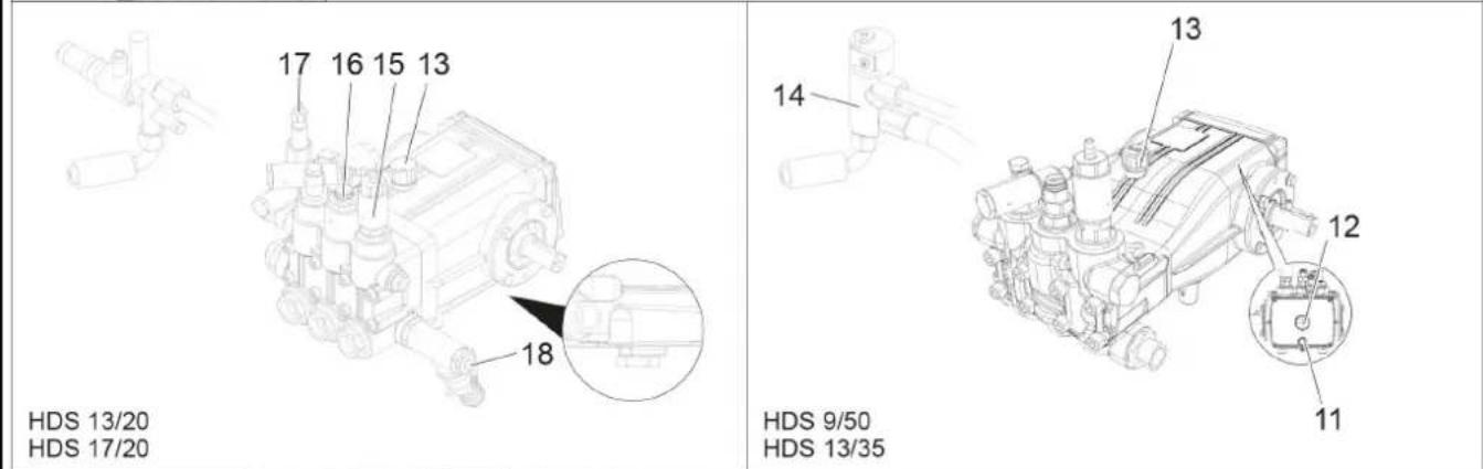
text_image
17 16 15 13 18 HDS 13/20 HDS 17/20 14 13 12 11 HDS 9/50 HDS 13/35
text_image
20 19text_image
Technical diagram of a mechanical engine with numbered components labeled 1, 2, and 3natural_image
Technical line drawing of a mechanical assembly with two arrows pointing to components (no text or symbols)①Смазочен нипел
natural_image
Technical line drawing of a mechanical assembly with two directional arrows indicating movement or force directions (no text or symbols present)HD 9/23 GeTr1 + HD 9/23 DeTr1
Измерено: 105
Гарантирано: 107
HDS 13/20 DeTr1
Измерено: 97
Гарантирано: 100
HDS 13/35 DeTr1 + HDS 9/50 DeTr1
Измерено: 100
Гарантирано: 102
HDS 17/20 DeTr1
Измерено: 100
Гарантирано: 102
OPTIONAL

H. Jenner
Chairman of the Board of Management

S. Reiser
Manager Regulatory Affairs & Certification
71364 Winnenden (Germany)
Тел.: +49 7195 14-0
Факс: +49 7195 14-2212
Виненден, 2023/01/01
Технически данни
text_image
Technical diagram of a truck's internal components with numbered labels pointing to various partstext_image
Labeled diagram of a mechanical or electrical component with numbered parts and control buttons0/ΘШІРУЛІ = Θшірулі
text_image
ESM3710-N SET P ✓ EMKO °C °F S P 8.8:8.8natural_image
Pure technical line drawing of a mechanical valve assembly without any text, labels, or symbolsnatural_image
Pure technical line drawing of a mechanical valve assembly without any text, labels, or symbolsnatural_image
Technical line drawing of a mechanical assembly with two connectors and a central pipe (no text or symbols)natural_image
Technical line drawing of a mechanical component with an arrow indicating a directional component (no text or symbols present)natural_image
Technical line drawing of a mechanical assembly with no visible text or symbolstext_image
Technical diagram of an engine showing labeled components and motion arrowsnatural_image
Technical line drawing of a mechanical assembly with three arrows pointing to specific components (no text or symbols present)①Майлайтын емік
natural_image
Technical line drawing of a mechanical assembly with two directional arrows indicating movement or force directions (no text or symbols present)HD 9/23 GeTr1 + HD 9/23 DeTr1
Өлшенді: 105
HDS 13/35 DeTr1 + HDS 9/50 DeTr1
Өлшенді: 100

H. Jenner
Chairman of the Board of Management

S. Reiser
Manager Regulatory Affairs & Certification
Winnenden, 2023/01/01
text_image
Technical schematic diagram of a mechanical assembly with labeled components and directional arrows indicating movement or force directions.حل براغى العجلة.
text_image
Technical diagram of an engine with numbered components labeled 1, 2, and 3natural_image
Technical line drawing of a mechanical assembly with labeled components and arrows indicating motion (no text or symbols present)text_image
Technical diagram of an internal combustion engine assembly with numbered components and exploded views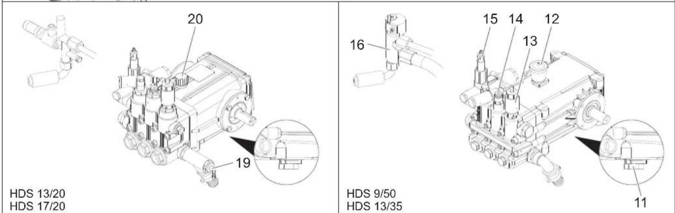
text_image
HDS 13/20 HDS 17/20 20 19 16 15 14 12 13 HDS 9/50 HDS 13/35 11
text_image
Technical diagram of a mechanical assembly with labeled parts 17 and 18, showing structural components and alignment indicators.natural_image
Pure mechanical diagram of a valve assembly without any text, numbers, or symbolsnatural_image
Pure mechanical assembly diagram without any text, numbers, or symbolsnatural_image
Technical line drawing of a mechanical assembly with no visible text or symbolsnatural_image
Technical line drawing of a mechanical device with labeled components (no readable text or symbols)text_image
ESM3710-N °C °F S P 8.8:8.8 SET P ✓ OKKOretirement 50 10,20,50
natural_image
Mechanical assembly diagram showing a linkage mechanism with no visible text or symbolstext_image
Diagram showing labeled icons for kitchen utensils and a toolbar, with numbered annotations 1 and 2 pointing to specific items.1 خزان ال-owned ( Yeشر شرطى)
2两项式式式式式式式式式式式式式式式式式式式式式式式式式式式式式式式式式式式式式式式式式式式式式式式式式式式式式式式式式式式式式式式式式式式式式
مسدس الرش اليدوي
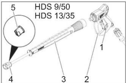
text_image
HDS 9/50 HDS 13/35text_image
Technical diagram of a vehicle's internal components with numbered parts for identification24 23 22 21
49 48
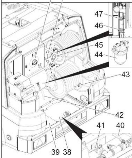
text_image
47 46 45 44 43 42 41 40 39 38text_image
Technical diagram of a garbage truck with numbered parts and exploded view, showing internal components and assembly details.natural_image
Black and white icon of a hand giving a thumbs-up gesture (no text or symbols)THANK YOU!
Register your product and benefit from many advantages.
www.kaercher.com/welcome ★★★★★

Rate your product and tell us your opinion.
natural_image
Icon showing a gear and wrench inside a square frame (no text or symbols)www.kaercher.com/dealersearch
Alfred Kärcher SE & Co. KG
Alfred-Kärcher-Str. 28-40
71364 Winnenden (Germany)