USER MANUAL Stig 1200 STIGA
2.3. STOPPING AND TURNING OFF THE ROBOT LAWN MOWER IN SAFE CONDITIONS 7
3. INTRODUCTION 8
3.1. GENERAL INTRODUCTION 8
3.1.1. PURPOSE OF THE MANUAL 8
3.1.2. INSTRUCTIONS ON READING FROM SMARTPHONES 8
3.2.PRODUCT OVERVIEW 9
3.2.1. GENERAL DESCRIPTION 9
3.2.2. MAIN COMPONENTS 10
3.3.UNPACKING 11
3.4. SYMBOLS AND NAMEPLATES 12
3.5. GENERAL INSTRUCTIONS ON HOW TO READ THE MANUAL 13
4. INSTALLATION 14
4.1. GENERAL INFORMATION FOR INSTALLATION 14
4.2. INSTALLATION COMPONENTS 14
4.3. INSTALLATION REQUIREMENTS CHECK. 15
4.3.1. GARDEN ASSESSMENT: 15
4.3.2. CHECKS FOR THE INSTALLATION OF THE CHARGING BASE AND POWER SUPPLY: 15
4.3.3. MAIN VERIFICATIONS FOR THE INSTALLATION OF THE PERIMETER CABLE: 17
4.4. CRITERIA FOR INSTALLING THE PERIMETER CABLE 19
4.4.1. PERIMETER CABLE PLACEMENT 19
4.4.2. OBSTACLES DELIMITATION: 21
4.4.3. WALKWAYS FROM ONE AREA OF THE GARDEN TO ANOTHER 23
4.5. COMPONENTS INSTALLATION 23
4.5.1. INSTALLATION OF THE PERIMETER CABLE 24
4.5.2. SPLICING THE PERIMETER CABLE 25
4.5.3. CHARGING BASE INSTALLATION 26
4.5.4. RESISTOR INSTALLATION FOR SMALL PERIMETERS 28
4.6. CHARGE ROBOT LAWN MOWER AFTER INSTALLATION 29
4.7.PRODUCT SETTINGS 30
5. FUNCTIONS
39
5.1. SAFETY DEVICES CHECK FOR STARTING THE ROBOT LAWN MOWER 39
5.2. MANUAL FUNCTIONING OF THE ROBOT LAWN MOWER 40
5.3. DESCRIPTION OF THE CONTROLS ON THE ROBOT LAWN MOWER 41
5.3.1. SAFE STOP-STOP BUTTON 41
5.3.2. SAFE SHUTDOWN-SAFETY KEY 42
5.3.3. SWITCHING THE ROBT LAWN MOWER ON AND OFF - ON / OFF BUTTON 42
5.3.4. SCHEDULED PROGRAM / SINGLE WORK CYCLE SELECTION - SCHEDULED PROGRAM BUTTON..... 43
5.3.5. BLUETOOTH STATUS DISPLAY AND UNPAIRING- BLUETOOTH BUTTON 45
5.3.6. ALARM STATUS DISPLAY - ALARM ICON 45
5.3.7. BATTERY CHARGE LEVEL DISPLAY-BATTERY ICON 46
5.3.8. STARTING THE ROBOT LAWN MOWER - START BUTTON 46
5.4. CHARGING BASE FUNCTION 47
5.5. BATTERY CHARGING 47
5.6. CUTTING HEIGHT ADJUSTMENT 48
6. MAINTENANCE 49
6.1. SCHEDULED MAINTANANCE 49
6.2.PRODUCT CLEANING 50
6.3. CUTTING BLADES REPLACEMENT 52
6.4. WINTER BATTERY MAINTENANCE AND STORAGE 53
6.5. BATTERY REPLACEMENT 53
7. TROUBLESHOOTING 54
7.1. MAIN MESSAGES FROM THE APP 55
8. TRANSPORT, STORAGE AND DISPOSAL 57
8.1. TRANSPORT 57
8.2. STORAGE 57
8.3. DISPOSAL 57
9 ACCESSORIES 58
10.WARRANTY 59
10.1.WARRANTY COVERAGE 59
1. MODELS AND TECHNICAL DATA
1.1. MODELS
This manual refers to the models Stig 300, Stig 600, Stig 1200.

1.2. TECHNICAL DATA - STIGA STIG
| SPECIFICATIONS | UNIT OF MEASURE | STIGA Stig 300 | STIGA Stig 600 | STIGA Stig 1200 |
| Dimensions (WxHxD) | [mm] 413 | x 252 x 560 413 x 252 x | 560 413 x 252 x 560 | |
| Weight of the robot lawn mower | [kg] 7.4 7 | 6 8 | | |
| Cutting height (Min-Max) | [mm] 20-60 | 20-60 20-60 | | |
| Blade diameter | [mm] | 180 | 180 | 180 |
| Cutting speed | [rpm] | 2850+/-50 | 2850+/-50 | 2850+/-50 |
| Speed of movement | [m/min] | 22 | 22 | 22 |
| Maximum slope | % | 45 | 45 | 45 |
| Maximum slope along the perimeter | % | 20 | 20 | 20 |
| Type of electric traction motor | - | Brushless | Brushless | Brushless |
| Type of cutting system | - | 4 pivoting cutting blades | 4 pivoting cutting blades | 4 pivoting cutting blades |
| Cutting device code | - | 322104105/0 | 322104105/0 | 322104105/0 |
| Type of electric cutting motor | - | Brushless | Brushless | Brushless |
| Sound power level detected | [dB] (A) | 57 | 57 | 57 |
| Uncertainty of noise emissions, KWA | [dB] (A) | 1.47 | 1.47 | 1.47 |
| Sound power level guaranteed | [dB] (A) | 59 | 59 | 59 |
| Acoustic level audible by the operator | [dB] (A) | 46.3 | 46.3 | 46.3 |
| IP rating of the robot lawn mower | - | IPX5 | IPX5 | IPX5 |
| IP rating of the charging station | - | IPX1 | IPX1 | IPX1 |
| IP rating of the power supply | - | IP67 | IP67 | IP67 |
| Robot lawn mower operating ambient temperature [°C] | [°C] | 0 - 50 | 0 - 50 0 - 50 | |
| Charging station operating ambient temperature [°C] | [°C] | -10 - 50 | -10 - 50 | -10 - 50 |
| Power supply ambient operating temperature [°C] | [°C] | -10 - 50 | -10 - 50 | -10 - 40 |
| Work capacity | [m²] | 300 | 600 | 1200 |
| Power supply | - | Input: 100-240vac | Input: 100-240vac | Input: 100-240vac |
| 1.2 A | 1.2 A | 1.2 A |
| Output: 30Vcc 2A | Output: 30Vcc 2A | Output: 30Vcc 2A |
| Battery model | - | 25.2 - 25.9 V | 25.2 - 25.9 V | 25.2 - 25.9 V |
| 2 Ah | 2.5 Ah | 5 Ah |
| Charging time | [min] | 60 | 80 | 150 |
| Bluetooth | - | 4.2 4.2 | 4.2 | |
2. SAFETY
In the design of the device, special attention has been paid to aspects that can cause risks to the safety and health of people. The purpose of this information is to sensitize users to prevent any risk, avoiding behaviours that do not comply with the regulations reported.

DANGER:
Before using the robot lawn mower you must know all the information contained in this document.

DANGER:
This robot lawn mower is not intended to be used by children and people with reduced physical, sensory or mental abilities or with lack of experience and knowledge.
ELECTRICAL HAZARD:
Before carrying out any adjustment or maintenance intervention, disconnect the power supply and activate the safety device.
ELECTRICAL HAZARD:
Do not use the robot lawn mower with a damaged transformer power cable. A damaged cable can lead to contact with live parts. The cable must be replaced by the manufacturer or its assistance service or by a person with adequate qualifications, in order to prevent any risk.
ELECTRICAL HAZARD:
Only use the battery charger and power supply provided by the manufacturer. The use of an inappropriate charger and power supply can cause electric shocks and / or overheating.

CAUTION:
In case of leakage of liquid from the battery, the affected components must be washed with water / neutralizer.
Avoid any direct contact with the battery liquid.
If the liquid comes into contact with the eyes, call a doctor immediately.

CAUTION:
During the operation of the robot lawn mower, make sure that there are no people, especially children, or\and pets, in the operating area. Otherwise, program the activity of the robot lawn mower during the hours when there are no people in that area.

CAUTION:
The operational area must be limited by a non-passable fence.
Make the fence suitable or supervise the robot lawn mower during its operation.

CAUTION:
Only use original spare parts.
TIGA

CAUTION:
Do not modify, tamper with, elude or eliminate the safety devices installed.

WARNING:
Check that there are no toys, tools, branches, clothing, or other items on the lawn that could damage the device.

BAN:
Do not sit on top of the robot lawn mower.

BAN:
Never lift the robot lawn mower to inspect the blade or to transport it when it's started. Do not put your hands and feet under the device.

BAN:
Do not use the robot lawn mower when a sprinkler is in operation.

BAN:
Do not wash the robot lawn mower with high pressure water jets, and do not immerse it, partially or completely, in water.

BAN:
Do not use the robot lawn mower if it is not perfectly intact in all its parts. In case of damage replace the affected parts.

BAN:
It is absolutely forbidden to use and recharge the robot lawn mower in explosive and inflammable environments.

OBLIGATION:
Visually check the robot lawn mower at regular intervals to make sure the blades and mowing mechanism are not worn out or damaged. Make sure that the robot lawn mower is in good operating conditions.

OBLIGATION:
Read the entire manual carefully, especially all safety information, and make sure you fully understand it. Follow the operating, maintenance and repair instructions carefully.

OBLIGATION:
Operators carrying out maintenance and repair interventions must be fully familiar with its specific characteristics and safety standards.

GLOVES OBLIGATION:
Use personal protection foreseen by the Manufacturer. Always use protective gloves when working on the cutting mechanism.
2.2. SAFETY INSTRUCTIONS

OBLIGATION:
Read carefully before use and store for future reference.
2.2.1. SAFE OPERATING PROCEDURES
Training
a. Read the instructions carefully, learn the controls and the correct use of the machine.
b. Never allow children, persons with reduced physical, sensory or mental capabilities, or lack of experience and knowledge, or persons unfamiliar with these instructions, to operate the machine. Local regulations may limit the age of the operator.
c. The operator, or user, is to be held responsible for accidents or hazards involving third parties or third party equipment.
Preparation
a. Make sure that the automatic system of perimeter delimitation is installed correctly as indicated.
b. Periodically check the area where the machine is used and remove stones, sticks, cables and any other foreign objects that may interfere with its operation.
c. Periodically carry out a visual inspection of the blades, blade bolts and of the cutting unit to check that they are not worn out or damaged. Replace worn out or damaged blades and bolts in pairs to maintain the balance of the machine.
d. Warning signs must be placed around the working area of the machine if it is used in public areas or areas open to the public. Signs must read as follows: "Warning! Automatic lawn mower! Keep away from the machine! Children must be supervised!"
2.2.2. OPERATION
a. Do not operate the machine with defective guards or safety devices that are not present, for example without protections.
b. Do not put hands or feet near or under the rotating parts. Always keep away from the drain opening.
c. Do not touch any moving parts of the machine until they have come to a complete stop.
d. Always wear sturdy shoes and long trousers when operating the machine.
e. Never lift or transport the machine when the motor is running.
f. Remove the disabling device from the unit:
- Before removing an obstruction;
- Before checking, cleaning or working on the machine.
g. Do not leave the machine in operation unattended in the presence of pets, children or other people nearby.
Maintenance and storage
a. Tighten all nuts, bolts and screws securely for safe operation of the machine.
b. Frequently check the robot lawn mower for wear or deterioration.
c. For safety reasons it is necessary to replace worn out or damaged parts.
d. Make sure that the blades are replaced only with suitable spare parts.
e. Make sure the batteries are recharged using the correct charger recommended by the manufacturer. Incorrect use can cause electric shock, overheating or leakage of corrosive liquid from the battery.
f. In case of electrolyte leaks, wash with water / neutralizing agent and consult a doctor in case of contact with eyes, etc.
g. Machine maintenance must be carried out in accordance with the manufacturer's instructions.
Battery / battery charger

WARNING:
Lithium-ion batteries can explode or cause fires if disassembled, exposed to water, fire or high temperatures or in the event of a short circuit. Handle the battery carefully, do not disassemble it and avoid any type of improper electrical or mechanical stress. Avoid exposing the battery to direct sunlight.
NOTE: It is recommended to use only original products supplied by the manufacturer. Non- original or inadequate products can cause damage to the robot lawn mower or can be dangerous for people, animals and things.
a. The battery should only be installed and / or removed from the robot lawn mower by the retailer or a service centre.
b. Store the unused battery in a safe place away from sources of heat or objects that can cause short circuits (pegs, screws, metal objects of various kinds).
c. Use the battery charger away from flammable surfaces or substances, and in preferably dry places.
d. Transport the battery and the battery charger in the original packaging.
Environmental protection
NOTE: Safeguarding the environment must be a relevant and priority aspect of machine use, of benefit to the community and the environment we live in.
a. Dispos of packaging and damaged parts as required by local regulations in the country of use.
b. Dispos of electrical equipment (bot lawn mower, battery, power supplies, etc.) as per European Directive 2020/19 / EU and in compliance with the national standards. For further information on the disposal, contact your retailer or a domestic waste collection service.
c. Separate collection of products and packaging is recommended.
2.3. STOPPING AND TURNING OFF THE ROBOT LAWN MOWER IN SAFE CONDITIONS

OBLIGATION:
Always switch off the robot lawn mower in safe conditions before any cleaning, transport or maintenance operation.
Requirements and obligations:
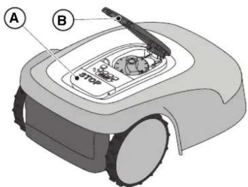
Procedure:
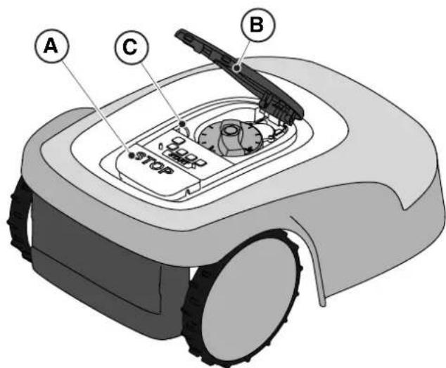
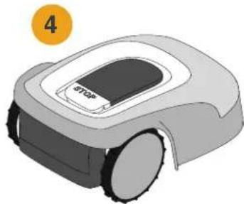
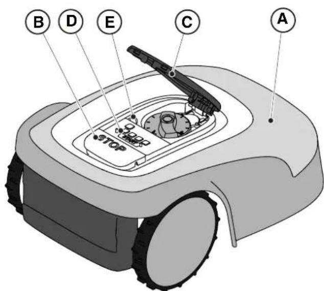
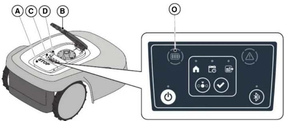
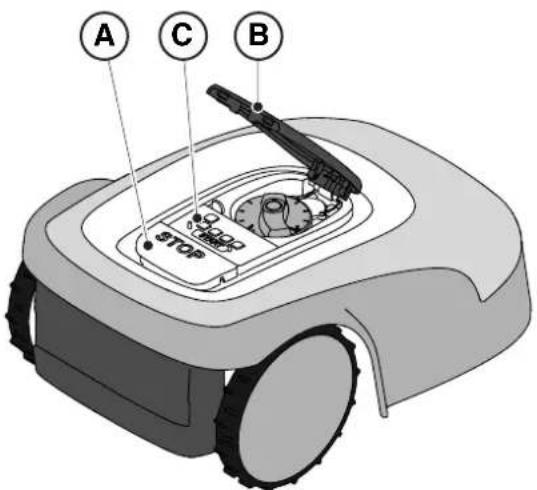
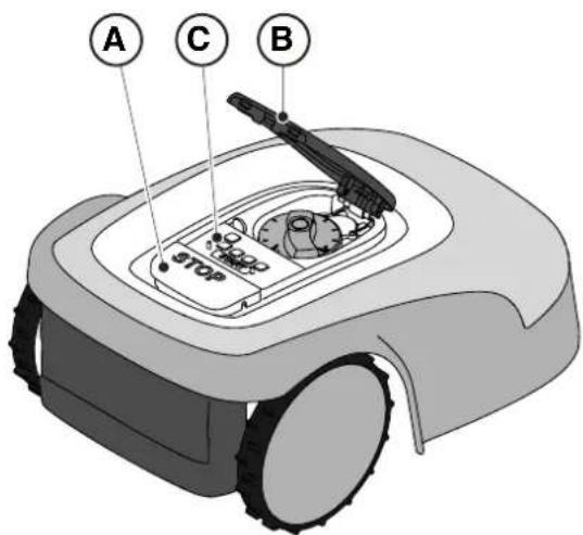
- Press the "STOP" (A) button to stop the robot lawn mower safely and open the protective cover (B).
- Disengage the safety key (C) to switch off the robot lawn mower in safe conditions.
- Close the protective cover (B).
- The robot lawn mower is stopped or switched off in a safe condition.
3. INTRODUCTION
3.1. GENERAL INTRODUCTION
3.1.1. PURPOSE OF THE MANUAL
This manual is an integral part of the device and it is intended to provide the information necessary for its use.
Keep this manual for the entire life of the device, so that it is always available in case of need.
The recipient of the manual is the user of the device, who is required to carefully read the information contained therein and apply it rigorously to protect people's safety and to avoid damage.
The information is drawn up in the original language of the manufacturer (Italian) and translated into any other languages for legislative and/or commercial needs.
The following symbols have been adopted to highlight important texts.

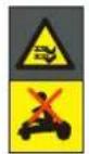
DANGER\CAUTION\WARNING:
The pictograms contained in a triangle with a yellow background and a black line indicate danger \ caution\ warning.

BAN:
The pictograms contained in a crossed-out circle with a white background and a red stroke indicate a ban.

OBLIGATION:
The pictograms contained in a circle with a blue background indicate an obligation.
NOTE: The texts shown in this form indicate technical information of particular importance, which should not be ignored.
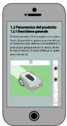
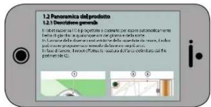
3.1.2. INSTRUCTIONS FOR READING FROM SMARTPHONE
For better readability of the user manual, it is recommended to keep the smartphone in an horizontal position, as shown in the picture.


3.2.PRODUCT OVERVIEW
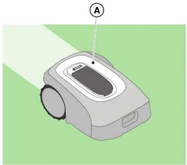
3.2.1. GENERAL DESCRIPTION
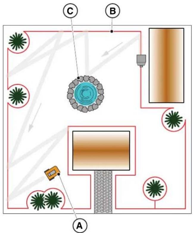
The robot lawn mower (A) is designed and built to automatically cut garden grass at any time of day and night.
According to the different characteristics of the surface to be cut, the lawnmower robot can be programmed to work on several areas delimited by the perimeter cable.
When operating, the robot lawn mower mows the area delimited by the perimeter cable (B).
When the robot lawn mower detects the perimeter cable (B) or encounters an obstacle (C) it changes trajectory randomly.
Based on the random operation principle, the robot lawn mower mows the delimited lawn automatically and completely.
Any other usage may be hazardous and harm persons and/or damage things. Improper use includes (for example, but not limited to): transporting people, children or animals on the machine; being transported by the machine; using the machine to pull or push loads; using the machine for cutting non-grass vegetation.
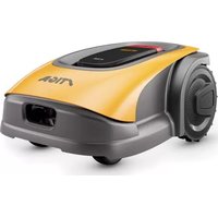
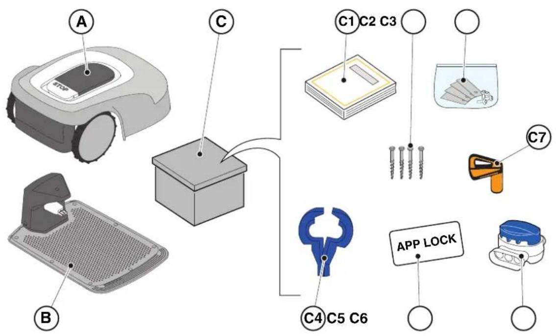
3.2.2. MAIN COMPONENTS
(A) Robot lawn mower
(B) Charging base
(C) Starter kit
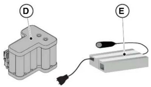
(D) Battery (inside the robot lawn mower)
(E) Charging base power supply
(C1) Instruction manual
(C2) Charging base fixing screws
(C3) Blister with blades and fixing screws
(C4) Charging Base connectors
(C5) App Lock Label
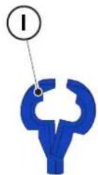
(C6) Joint for perimeter cable
(C7) Safety key
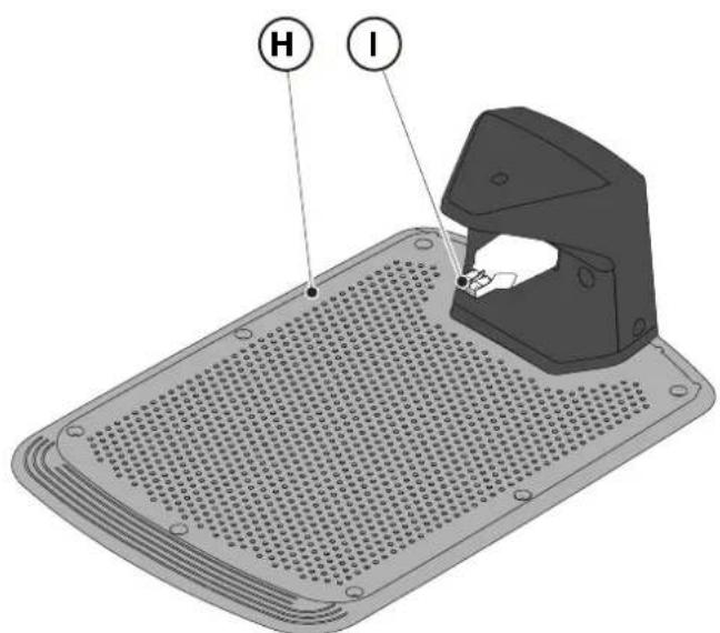
- Installation kit (Optional for Stig 600 and Stig 1200)
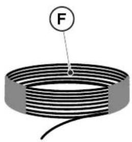
(F) Perimeter cable
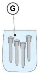
(G) Perimeter cable fixing pegs
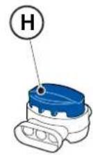
(H) joint for perimeter cable
(I) Charging base connectors
See Chapter 9 "Accessories"
3.3.UNPACKING
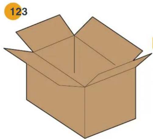
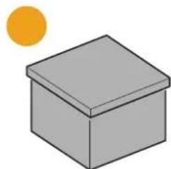
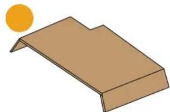
Below all the steps to perform the correct unpacking are described:
- Open the box of the robot lawn mower;
- Take out the " Starter Kit" box;
- Take out the upper containment carton;
- Take out the robot lawn mower;
- Take out the charging base.


3.4. SYMBOLS AND NAMEPLATES
Below all the symbols on the robot lawn mower are listed:
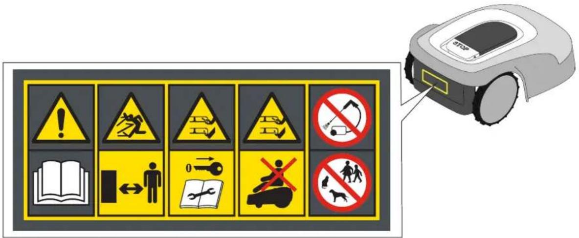

WARNING:
Read the user instructions before starting the product.

WARNING:
Danger of projections of objects against the body.
Keep an adequate safe distance from the machine while it is running.
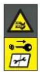
WARNING:
Do not put hands and feet near or under the opening of the cutting means.
Remove the disabling device before operating on the machine or before lifting it.
WARNING:
Do not put hands and feet near or under the opening of the cutting means.
Do not stand on the machine.

BAN:
Do not use high pressure cleaners on the machine to clean or wash it.

BAN:
Make sure that there are no people (especially children, elderly or disabled) and pets in the working area during the operation of the machine.
Keep children, pets and other people at a safe distance when the machine is functioning.
All the symbols on the Battery are shown below:
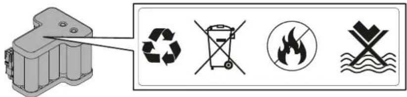

WARNING:
Read the user instructions before starting the product.


Do not dispose of the battery as normal household waste.
Dispose of the battery in the appropriate authorized collection centres.

Do not throw the battery into the fire and do not expose it to heat sources.

Do not immerse the battery in water and do not expose it to moisture.
3.5. GENERAL MANUAL READING INSTRUCTIONS
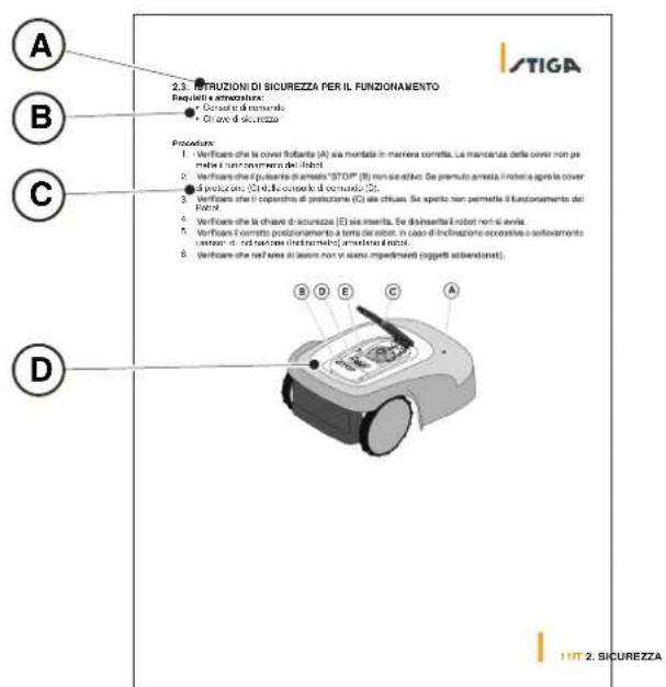
The criteria used for the preparation of this document are described below.
- Topic title (A)
- Requirements and equipment for carrying out the procedure (B)
- Description of the procedure (C)
- Descriptive pictures of the procedure (D)
- App section title (E)
- App navigation procedure (F)
4. INSTALLATION

CAUTION:
Do not modify, tamper with, elude or eliminate the safety devices installed.
NOTE: For further clarification on the installation of the product please contact a STIGA dealer.
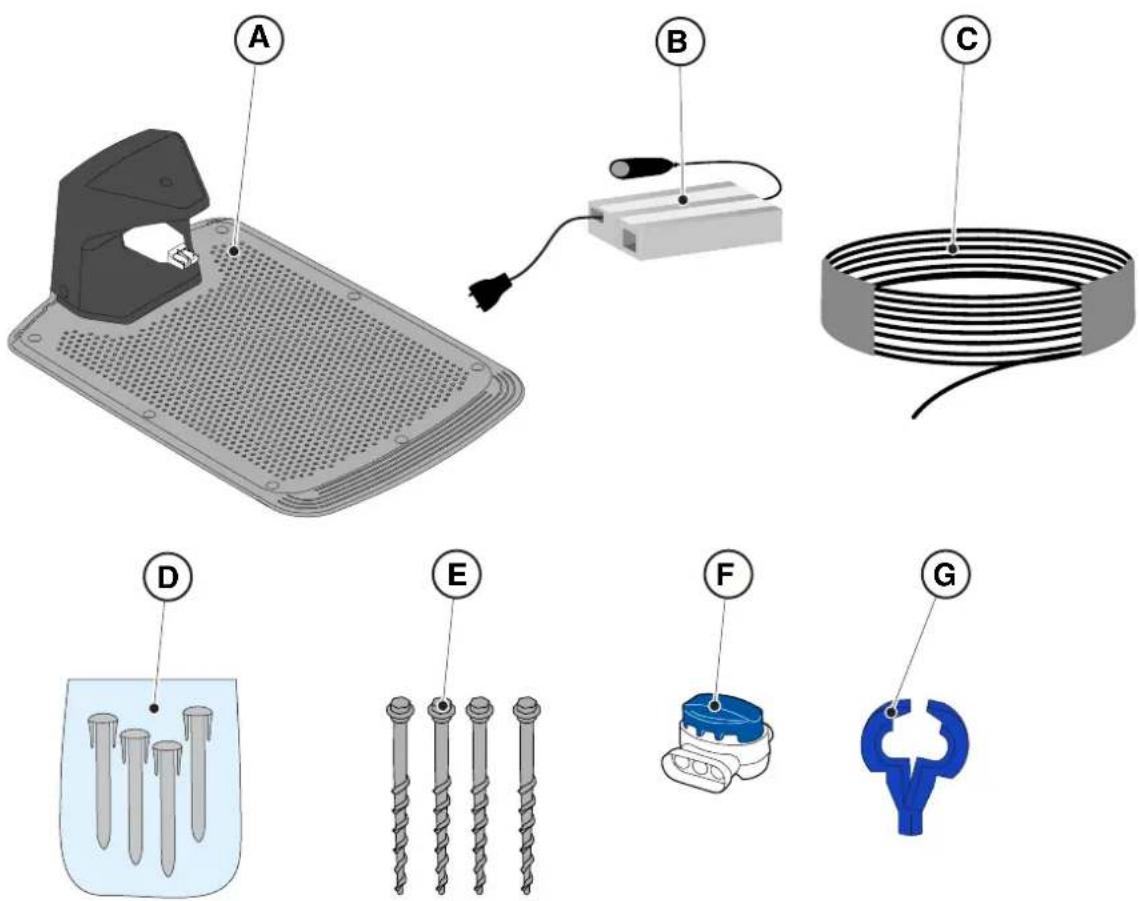
4.2. INSTALLATION COMPONENTS
(A) Charging Base
(B) Power supply
(C) Perimeter cable (included in the installation Kit)
(D) Perimeter cable fixing pegs (included in the installation Kit)
(E) Charging base fixing screws
(F) Joint for perimeter cable (included in the installation Kit)
(G) Charging base connectors (included in the installation kit)
See Chapter 9 "Accessories"
4.3. VERIFICATION OF THE INSTALLATION REQUIREMENTS
Below the procedures to check the necessary requirements and prepare the garden before proceeding with the installation are described.
4.3.1. GARDEN VERIFICATION:
- Carry out a survey of the entire area for a correct detection of the state of the garden, of any obstacles and areas to be excluded.
- Check that the lawn to be mowed is uniform, free of holes, stones or other obstacles and, if necessary, carry out the appropriate environmental decontamination works.
NOTE: Level the ground so that no puddles form as a result of rain.
NOTE: At the first installation, the initial height of the grass must be within the operating range of the robot lawn mower: 20-60 mm. If necessary, prepare the garden using a traditional lawn mower.
4.3.2. CHARGING BASE AND POWER SUPPLY INSTALLATION CHECKS
ELECTRICAL HAZARD:
A socket must have been prepared near the installation area to connect it to electricity. Make sure that connection to the power supply network conforms to laws in force of the Country where it is used.
ELECTRICAL HAZARD:
Do not connect the power supply to an electrical outlet if the plug or the cable is damaged.
Do not connect or touch a damaged cable before it is disconnected from the power supply.
A damaged cable can lead to contact with live parts.
ELECTRICAL HAZARD:
The circuit provided must be protected by a residual current device (RCD) with an activation current not exceeding 30mA .
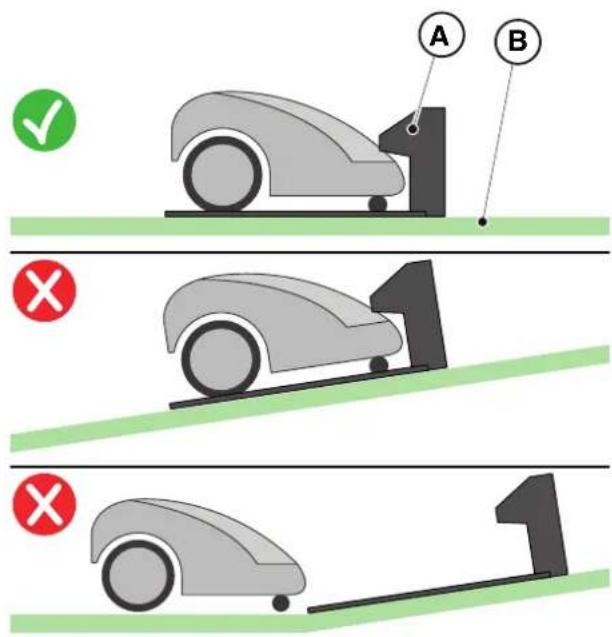
Procedure:
- Prepare a flat area at the edge of the lawn for positioning the charging base (A), preferably in the largest portion of the garden and near an electrical outlet.
- Make sure there is enough space to install the charging base on a straight section of the perimeter cable (B), so that the distance of the base from any curves is at least X = 200cm ; the ground must be perfectly flat at and compact in order to avoid the deformation of the surface of the charging base.
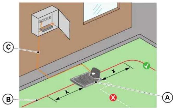

WARNING:
The power cable (C), power supply unit, extension cord and all other electric cables which do not belong to the product must remain outside the cutting area to maintain their distance from hazardous moving parts and prevent damage to cables which may come into contact with live parts.
- Make sure that the area chosen for installing the charging base (D) is at least 400cm away from the charging base (E) of a possible second robot lawn mower.

WARNING:
The excessive proximity between two charging bases could cause interference (See Par. 4.7.14)
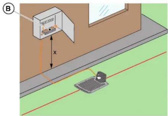
- Prepare the power supply installation area (B) so that in no weather conditions it can be immersed in water.
NOTE: It is preferable and recommended to install the power supply (B) in a closed compartment protected from atmospheric agents, in a position that is not easily accessible by unauthorized persons such as children (X > 160cm)
4.3.3. MAIN CHECKS WHEN INSTALLING THE PERIMETER CABLE:
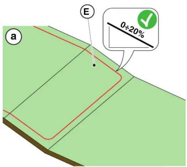
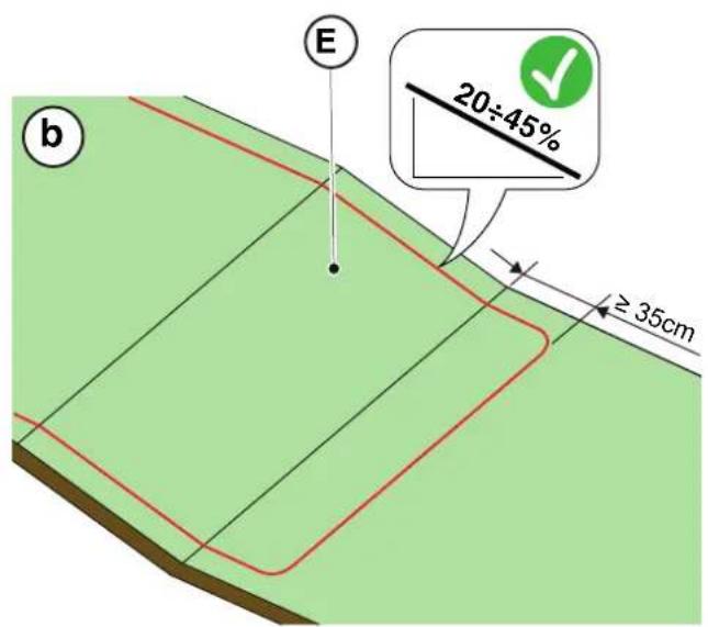
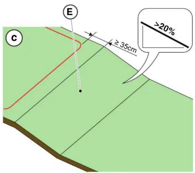
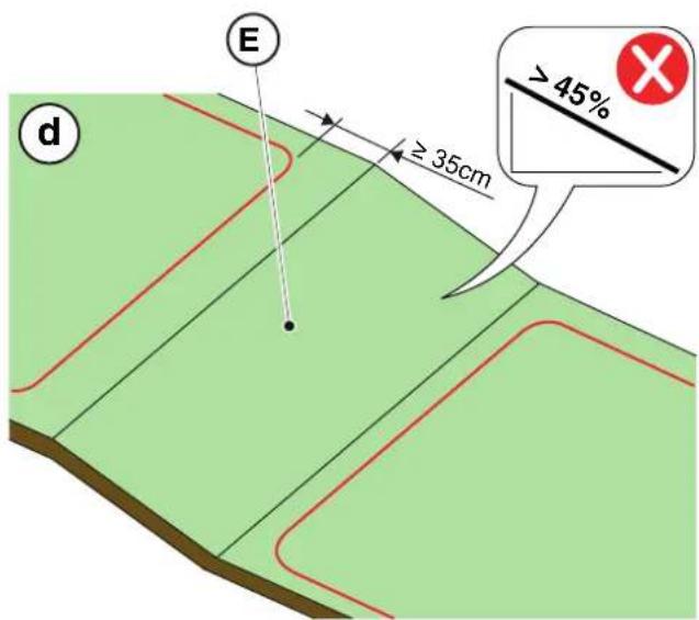
- Check that the maximum slope of the work area is less than or equal to 45% (E) and observe the rules shown in the images below:
a) if the slope is ≤ 20% the perimeter cable can be installed on it as shown in the image;
b) if the slope is >20% and ≤ 45% , the installation must include the slope area observing the distance indicated in the image;
c) if the slope is >20% and the slope area is not part of the part of the garden to be cut, the distance indicated in the image must be observed;
d) if the slope is >45% , the slope area must be excluded observing the distance indicated in the image.
TIGA

WARNING:
The robot can mow surfaces with a maximum slope of 45% .
In case of non-compliance with the instructions, the robot may slip and exit from the work area.

WARNING:
Areas with slopes greater than those permissible may not be mowed. Place the perimeter cable before the slope excluding that area of the lawn from being mowed.
- Check the entire work surface: assess the obstacles and areas to be excluded from the work area (F), which must be delimited with the perimeter cable (G).
4.4. CRITERIA FOR INSTALLING THE PERIMETER CABLE
4.4.1. PERIMETER CABLE PLACEMENT
Procedure:
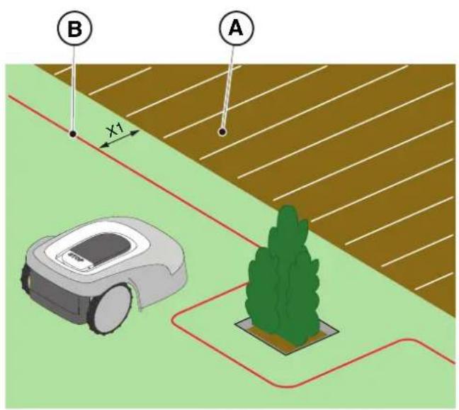
- If there is a pavement or path (A) at the same level as the lawn, arrange the perimeter cable (B) at X1 = 5cm from the edge of the pavement.
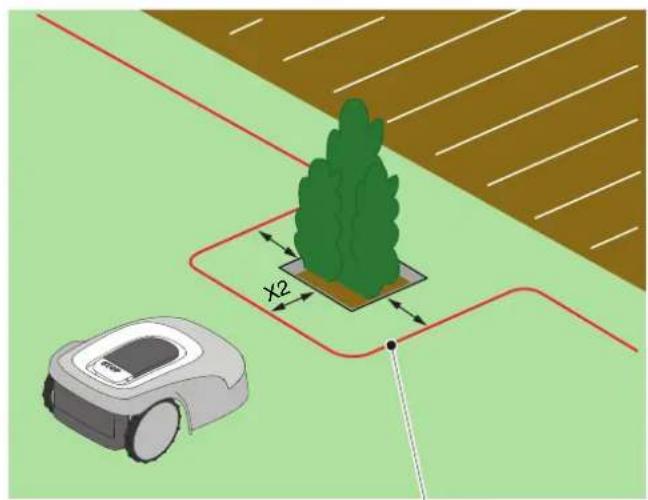
- In the vicinity of a level flower bed, a metal manhole, a shower surface or electrical cables, arrange the perimeter cable (C) at least X2 = 30 cm away.
C
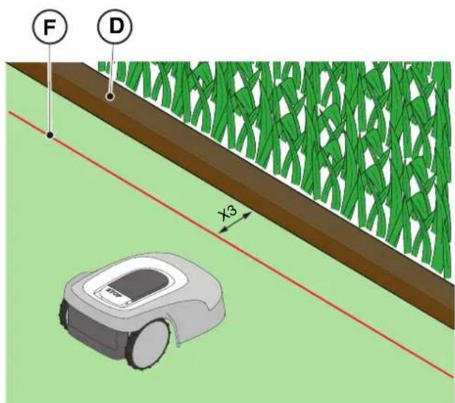
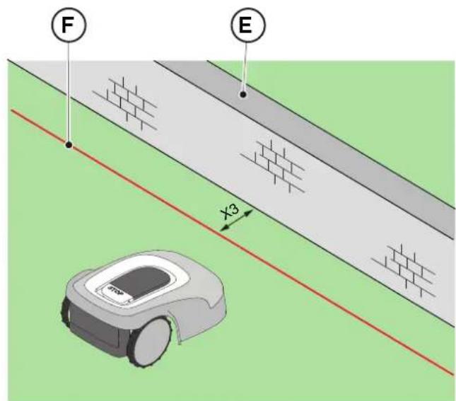
- If there is an obstacle, for example a ditch (D), a wall or a low wall (E), arrange the perimeter cable (F) at least X3 = 35 cm from the obstacle.
TIGA
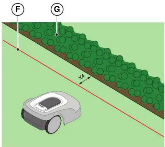
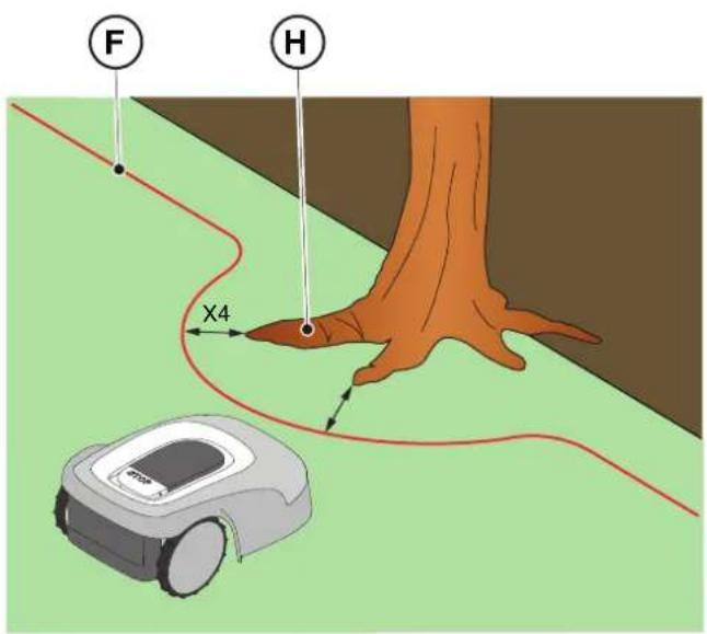
- If there is a hedge (G) or a plant with protruding roots (H), arrange the perimeter cable (F) at least X4 = 30 cm.
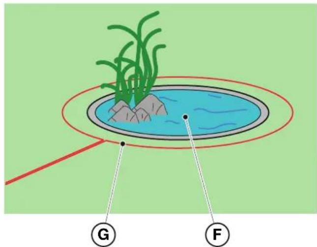
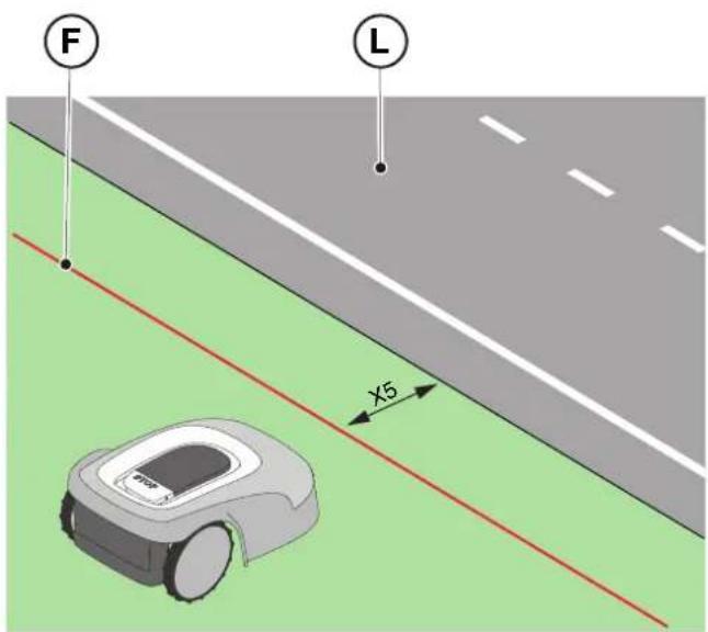
- If there is an infinity pool or pond (I), unsecured public roads (L), adjust the perimeter cable (F) at least X5 = 90 cm.

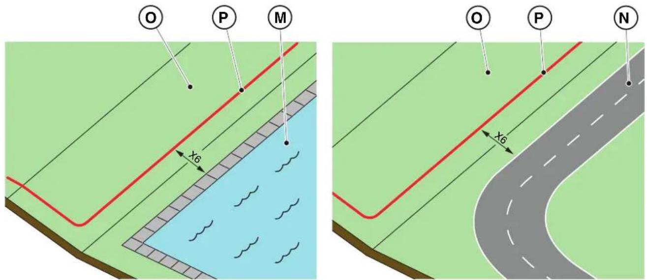
- If there is a swimming pool (M) or a road (N) at the end of a slope (O), arrange the perimeter cable (P) at least X6 = 150 cm.

WARNING:
If the slope is greater than 45% , the slope area must be excluded from the cutting area (See Par. 4.3).

CAUTION:
The operational area must be limited by a non-passable fence. Make the fence suitable or supervise the robot lawn mower during its operation.
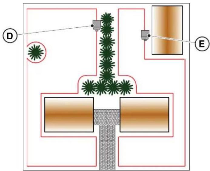
4.4.2. DELIMITATION OF OBSTACLES
Procedure:
-
If the minimum passage between two different sections of the perimeter cable is X ≥ 70cm , the obstacle can be delimited as shown in the figure (Q), overlapping the sections of the outward and return cables without crossing them (R).
-
To delimit the obstacle (S):
-
Place the perimeter cable up to the obstacle and go around it;
- Bring the cable back along the previous path overlapping it under the same nail, without creating intersections (R).
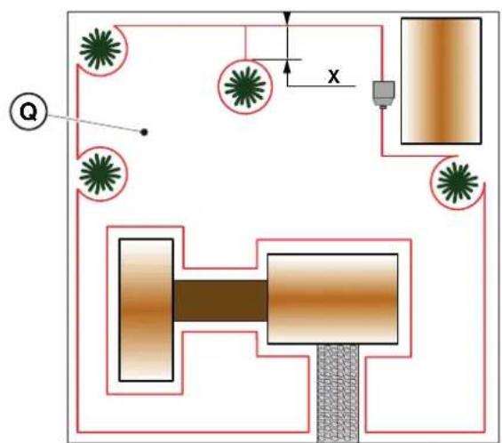
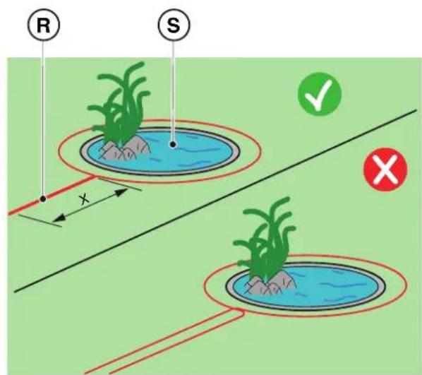
NOTE: For the robot lawn mower's correct functioning, the minimum length of the superimposed perimeter cable (R) must be X = 70 cm.
- If the minimum passage between two diff erent sections of the perimeter cable is X < 70cm the obstacle can be delimited by spacing the two sections of the outward and return cable by a height ≥ 30 cm as indicated in the fi gure (T), or, if the obstacle is strong enough, it can be left unprotected as shown in fi gure (U).
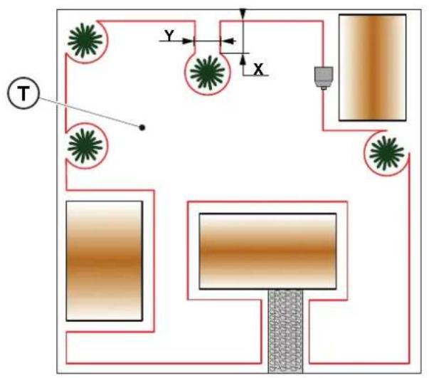
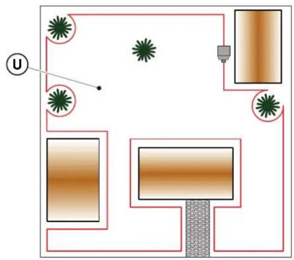
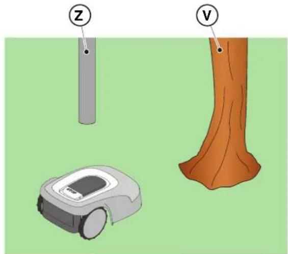
- In general, it is advisable to delimit obstacles, however if there are localized obstacles that resist impact, for example trees without protruding roots (V) or poles (Z), it is possible not to delimit them.
4.4.3. PASSAGES AMONG DIFFERENT AREAS OF THE GARDEN
Procedure:
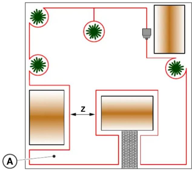
- In the case of corridors, the distance between two different sections of the perimeter cable must be Z ≥ 70 cm.
- In case of passage between two different sections of cable Z < 70 cm, the area (A) is to be considered a "Closed Area" and cannot be reached by the robot lawn mower automatically.
NOTE: For programming the robot lawn mower relating to the configuration of the garden with "Closed Area", see the procedure at Par. 4.7.5 "Closed Area".
4.5. COMPONENTS INSTALLATION
| ELECTRICAL HAZARD: Only use the battery charger and power supply provided by the manufacturer. Improper use may cause electric shock and/or overheating. | CAUTION: The circuit provided must be protected by a residual current device (RCD) with an activation current not exceeding 30 mA. |
| ELECTRICAL HAZARD: A socket must have been prepared near the installation area to connect it to electricity. Make sure that connection to the power supply network conforms to laws in force of the Country where it is used. | ELECTRICAL HAZARD: Connect the power supply only at the end of all the installation operations. If necessary during the installation, turn off the general power supply. |
4.5.1. INSTALLATION OF THE PERIMETER CABLE
POSITIONING WITH PEGS

CAUTION: Danger of cutting hands.

CAUTION: Danger of dust in the eyes.
Requirements and obligations:
- Low grass all the way - Hammer
- Perimeter cable - Gloves
Fixing pegs - Glasses
- Joints for perimeter cable - Electrician's scissors
Pliers

GLOVES OBLIGATION: Use protective gloves to avoid cutting your hands.

GLASSES OBLIGATION: Use safety glasses to avoid the danger of dust in the eyes.
Procedure:
- Place the perimeter cable (A) starting from the charging base installation area.
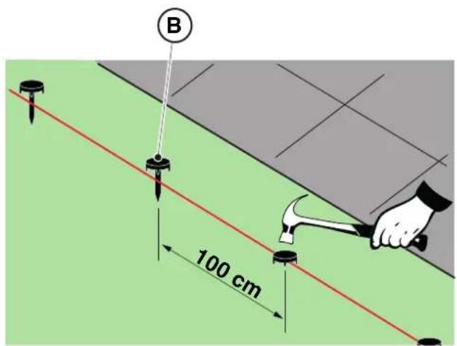
- Place the cable along the entire path, fixing it with the suitable pegs (B) spaced approximately 100cm apart, and observing the installation requirements (see Par. 4.3 and Par. 4.4).
- Leave 2m of cable or more to subsequently cut it to size in the final phase of connection.
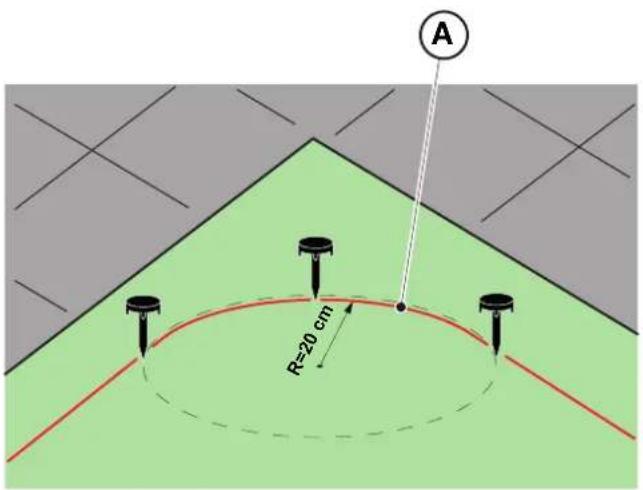
NOTE: In non-straight sections, make sure that the cable (A) does not get tangled. Position the cable in such a way as to form a regular curve with a radius of about 20cm
NOTE: The perimeter cable used for installation must be at least 40m long. If the cable is shorter, it will be necessary to install the resistor for small perimeters. (See Par. 4.5.4. and Chap. 9 "Accessories").

WARNING:
Make sure that the cable is in contact with the ground along its path to prevent the robot lawn mower from damaging it.
POSITIONING UNDERGROUND
(CARRIED OUT ONLY BY AUTHORIZATION RETAILER)
Turning to a STIGA retailer, the perimeter cable can also be installed using a specific wire-laying machine, without using pegs.
4.5.2. JUNCTION OF THE PERIMETER CABLE.

CAUTION: Danger of cutting hands.

CAUTION: Danger of dust in the eyes.
Requirements and obligations:
- Joint for perimeter cable - Gloves
Electrician's scissors - Glasses
- Pliers

GLOVES OBLIGATION: Use protective gloves to avoid cutting your hands.

GLASSES OBLIGATION: Use safety glasses to avoid the danger of dust in the eyes.
During the installation of the cable or in case of accidental breakage, it may be necessary to make junctions.
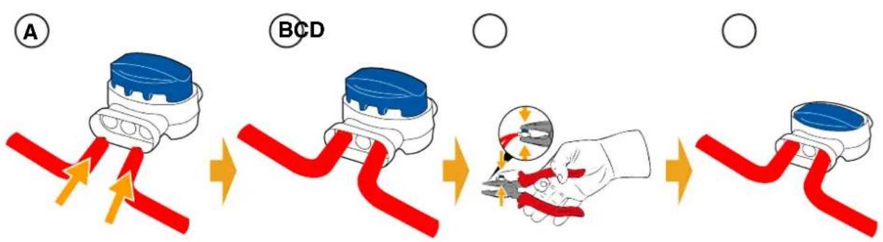
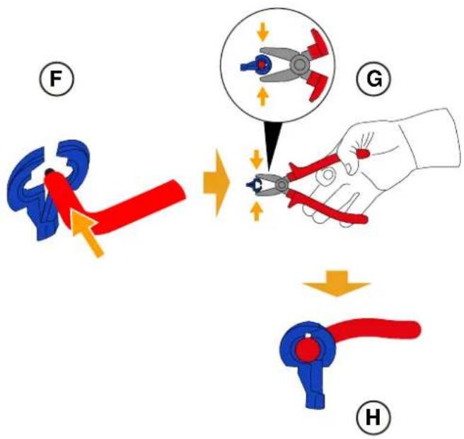
Procedure:
- Disconnect the charging base from the power supply.
- Place the perimeter cable as per position (A).
- Insert the ends of the cable into the joint as per position (B).
- Fully press the button on the upper side of the joint using a pair of pliers as per position (C).
- The perimeter cable is properly installed on the joint (D).

BAN: Do not use insulating tape or joints of any other type that do not guarantee correct insulation (cable lugs, terminals, etc.). The soil moisture causes oxidation and the interruption of the perimeter cable.
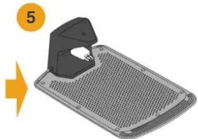
4.5.3. CHARGING BASE INSTALLATION
| CAUTION:
Danger of cutting hands. | CAUTION:
Danger of dust in the eyes. |
| ELECTRICAL HAZARD:
Connect the power supply only at the end of all the installation operations. If necessary during the installation, turn off the general power supply. | |
Requirements and obligations:
- Flat land - Compact soil
- Charging base - Perimeter cable
- Power supply - Fixing pegs
- Screwdriver - Hammer
Electrician's scissors -Gloves
- Glasses

GLOVES OBLIGATION:
Use protective gloves to avoid cutting your hands.

GLASSES OBLIGATION:
Use safety glasses to avoid the danger of dust in the eyes.
The charging base can be installed:
- aligned with the perimeter cable so that the robot can access it by navigating the perimeter cable clockwise.
Procedure:
- Check the installation requirements as shown in Par. 4.3.
- If necessary, prepare the ground so that the surface of the charging base (A) is at the same level as the lawn (B), the ground must be perfectly flat and compact in order to avoid deformation of the surface of the charging base.
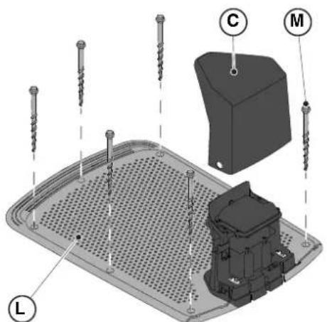
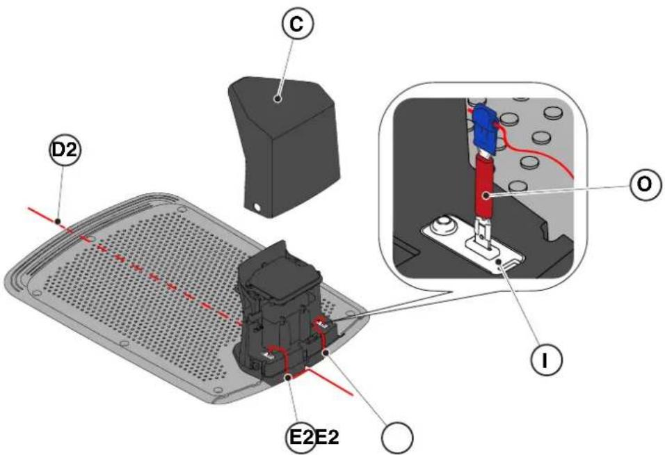
- Remove the cover (C).
-
Positioning the charging base:
-
Aligned to the perimeter cable (D2) so that the robot can access it by navigating the perimeter cable clockwise.
-
Insert the two ends of the cable into the appropriate slots (E2).
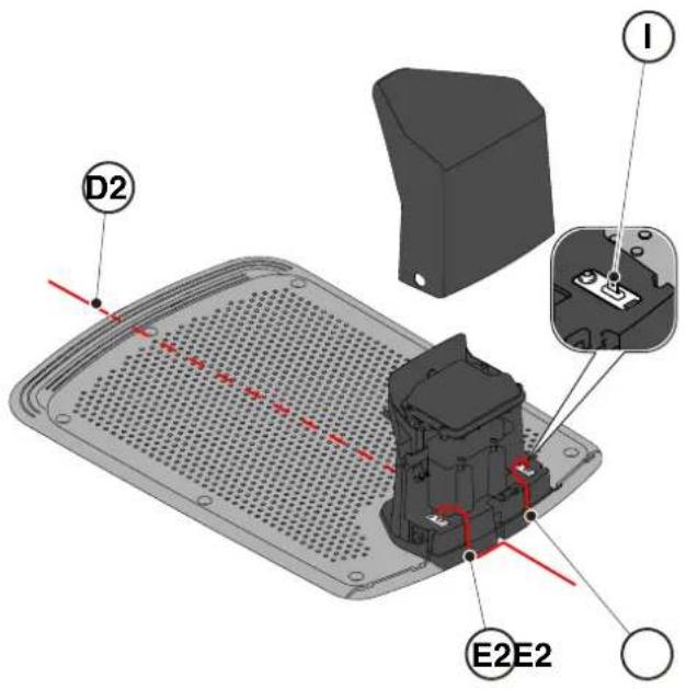
- Cut the ends of the cables to the exact length.
- Apply the self-drilling connectors on the cable (F), (G), (H).
- Connect the connectors to the terminals (I).
TIGA
- Secure the charging base (L) to the ground with the fixing screws (M).
- Reposition the cover (C).
- Connect the power supply connector to the charging base and then insert the power supply plug into the electrical outlet.
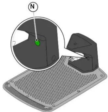
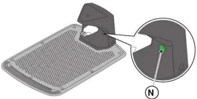
- When the robot lawn mower is not in the charging base, make sure that the indicator light on the charging base (N) is lit with a fixed light. (see Par. 5.4).

WARNING:
The power cable, power supply unit, extension cord and all other electric cables which do not belong to the product must remain outside the cutting area to maintain their distance from hazardous moving parts and prevent damage to cables which may come into contact with live parts.
NOTE: If necessary, it is possible to extend the power cable to the charging base by using the extension cables. Use a maximum of two 5-meters extension cables (see Chap. 9 "Accessories").
4.5.4. RESISTOR INSTALLATION FOR SMALL PERIMETERS
Requirements and obligations:
The perimeter cable used for the installation of the robot lawn mower must be at least 40m long. If the cable length is shorter, it is necessary to connect in series the resistor (see Chap. 9 "Accessories") with the perimeter cable.
Procedure:
After having positioned and secured the charging base correctly (see par. 4.5.3), proceed as follows:
- Remove the cover (C).
- Cut the ends of the cables to the exact length.
- Apply the self-drilling connectors on the cable (F), (G), (H). (See par. 4.5.3).
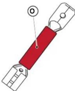
- Connect the resistor (O) to the terminal (I) of the charging base.
- Connect the respective perimeter cable to the resistor (O).
- Connect the other perimeter cable directly to the other terminal of the charging base.
4.6. CHARGING THE ROBOT LAWN MOWER AFTER INSTALLATION
Requirements and obligations:
Procedure:
- Recharge the robot lawn mower (see Par. 5.5).
NOTE: When charged for the first time, the batteries must remain connected for at least 2 hours.
4.7.PRODUCT SETTINGS
Requirements and obligations:
The automatic operation of the robot lawn mower requires a series of settings that can be made via mobile device (smart phone) iOS or Android with the "STIGA GO" App installed.
The iOS app is downloadable from the iOS App Store. The Android app is downloadable from the Google Play Store.
The following functions can be set up from the app. Check the table of contents to see which functions are available for your model:
- Start, stop and force the robot lawn mower to return to the charging base.
- Select the work mode in a closed area that cannot be reached autonomously by the robot lawn mower.
- Select the Scheduled Job / Single Cutting Cycle mode.
Schedule Working Hours for the days of the week.
- Set the Work Start Points to make cover the garden uniformly.
- Set the days of the week to perform the edge trimming.
- Enable a low energy eco mode.
- Enable and set the sensitivity of the Rain Sensor.
- Enable different users to use the robot lawn mower via app.
- Choose and contact your reference retailer.
NOTE: The images shown in this section are purely indicative and may differ over time from those of the product app.
| Stig 300 Stig 600 Stig 1200 |
| Border Cut | ✓ | ✓ | ✓ |
| Run Beside Wire | X | ✓ | ✓ |
| Go-To Cut Points | 135 | | |
| Eco Mode | X | X | ✓ |
| Rain Sensor | X | ✓ | ✓ |
| Closed Area | X | X | ✓ |
TABLE OF CONTENTS PRODUCT SETTINGS
4.7.1. PRELOGIN 31
4.7.2. SIGN UP 31
4.7.3. PAIRING 32
4.7.4. DEVICE PAGE 33
4.7.5.CLOSED AREA 33
4.7.6. SETTINGS 33
4.7.7. SPOT CUT / SCHEDULED 34
4.7.8. MOWING SESSIONS 34
4.7.9. GO-TO-CUT POINTS 35
4.7.10. BORDER CUT 36
4.7.11.ECO MODE 36
4.7.12. RAIN SENSOR 36
4.7.13. USER MANAGEMENT 37
4.7.14. DEALERS 37
4.7.15.MESSAGES 38
4.7.16.PROFILE 38
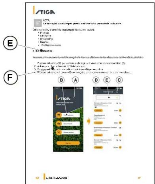
4.7.1.PRELOGIN
At the first access in the app you can:
- Access the information pages regarding STIGA retailers and products (A).
- Carry out the first registration (B).
- Log in for already registered users (C).

4.7.2. SIGN UP
The "Sign Up" section allows user registration and enables access to all functions of the app.
- The user can log in through their Google, Facebook and Apple (A) accounts, or create a new account by filling in the required fields (B).
- The registration procedure requires verification by e-mail (C).


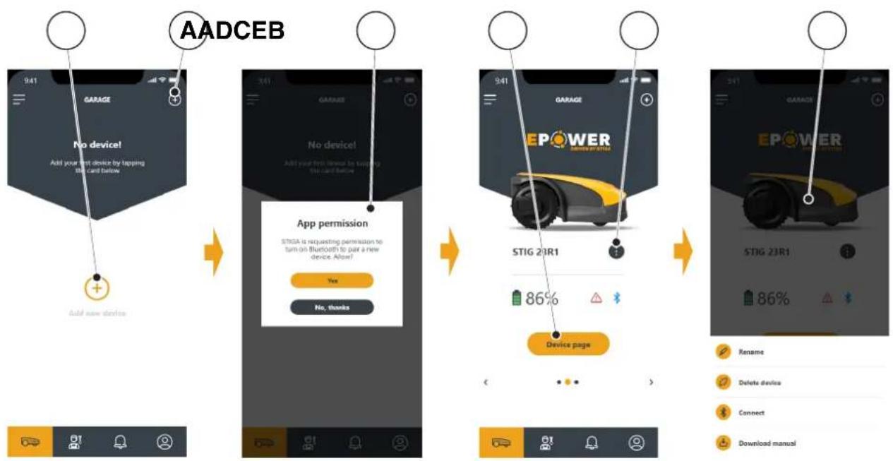
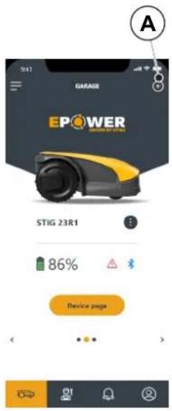
4.7.3. PAIRING
The "Pairing" section allows you to associate your mobile device with the robot lawn mower via bluetooth connection.
- Press the button (A) to access the bluetooth pairing pages.
- Confirm to authorize the pairing via bluetooth (B).
- Follow the guided procedure to pair the product.
- After the pairing is complete, the main page of the product will be displayed.
- Press the button (C) to access the product page.
- Press the button (D) to access the menu page (E), from which it is possible to rename, unpair and connect the robot lawn mower, or download the user manual.
NOTE: if the robot lawn mower is not detected by the mobile device, verify that the robot lawn mower is not paired with another device (See Par. 5.3.5).
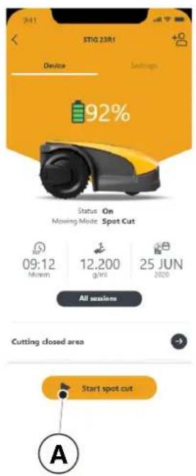
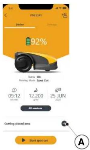
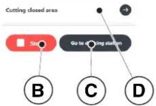
4.7.4. DEVICE PAGE
The "Device Page" section allows to make the robot lawn mower start working or to make it return to the charging base.
- Press the button (A) to start the robot lawn mower.
- Press the button (B) to stop the robot lawn mower.
- Press the button (C) to force the robot lawn mower to return to the base.
- Press on the field (D) to make the robot lawn mower start working in an area that cannot be reached independently. (See Par. 4.7.5)


4.7.5.CLOSED AREA
NOTE: Check the availability of this function on the STIGA.GO App.
The "Closed Area" section allows to start the robot lawn mower in an enclosed area normally excluded from the work area because it is not reachable, but in any case delimited by the perimeter cable. (See Par. 4.3)
- Press the button (A) to choose the "closed Area" mode.
- Place the robot lawn mower inside the closed area and follow the guided procedure.
NOTE: The user can choose whether to operate the robot lawn mower for the entire duration of the battery life or for a set shorter time.
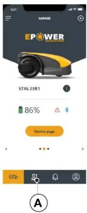
4.7.6. SETTINGS
The "Settings" section provides access to the robot lawn mower's settings screen.
- Press the button (A) to enter the Settings mode.
- Press the function (B) to perform the setting.
from the menu of the "Settings" section you can also:
- choose the unit of measurement (C),
- choose the date / time format (D),
- reset the robot lawn mower to factory settings (E).
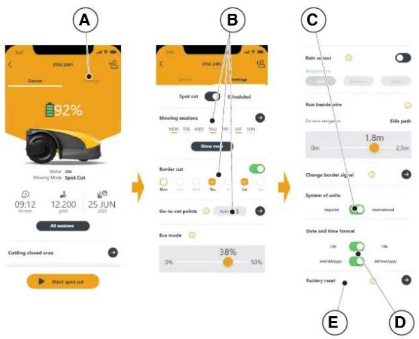
The "Spot Cut / Scheduled" selector (A) allows you to activate or deactivate the programmed work schedule.
The number of weekly hours to schedule are suggested by the app according to the size of the garden.
- If set to "Scheduled" the robot lawn mower works according to the scheduled work program.
- If set to "Spot Cut" the robot lawn mower works in a single work cycle.
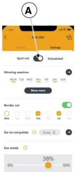
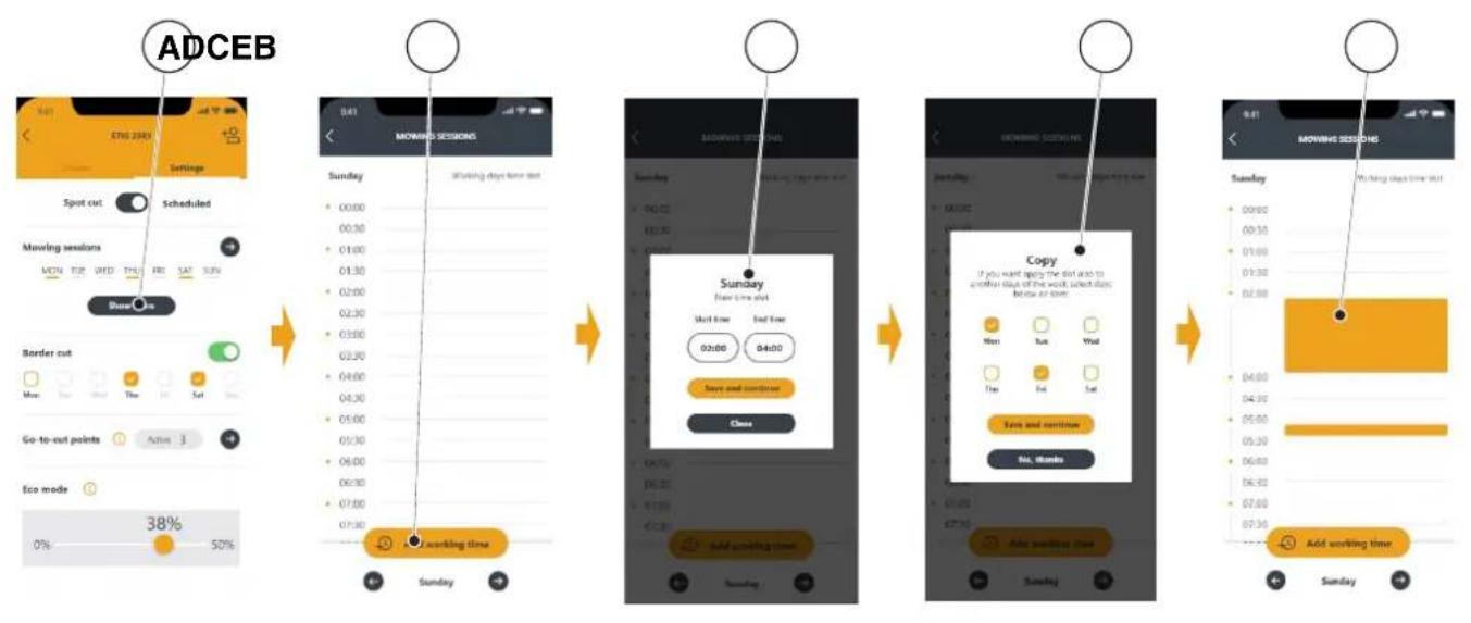
4.7.8. MOWING SESSIONS
The "Mowing sessions" section allows you to program the time and working days of the robot lawn mower. The number of weekly hours to schedule are suggested by the app according to the size of the garden.
- Press the button (A) to access the working hours setting menu and select a day of the week.
- Press the button (B) to add a new work schedule.
- Enter the work start and end times (C) and save.
- The user has the option of applying the same working hours to several days of the week (D).
- The working time will be displayed (E) within the day on which it is scheduled. By pressing on each working time it is possible to copy or delete it.
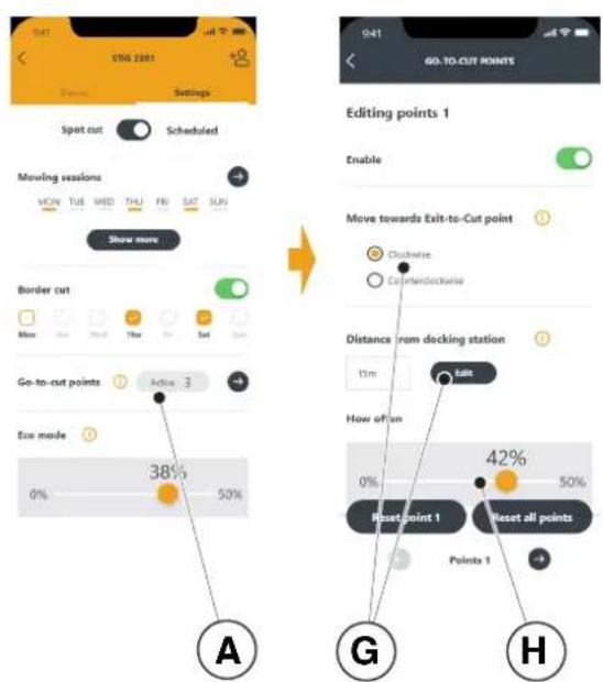
4.7.9. GO-TO CUT POINTS
NOTE: Check the availability of this function on the STIGA.GO App.
The section "Go-To-Cut Points" (A) allows you to set one or more starting points for the robot lawn mower's work in order to improve coverage in the different areas of the garden (see Par. 4.4). The number of settable start points depends on the model of the robot lawn mower.
The work start points are defined using the following parameters:
- Distance from the starting point to the charging base measured along the perimeter cable (G).
- Direction to reach the work point (clockwise or anticlockwise) (G).
Frequency of reaching the work point expressed in% of the total programmed work time (H).
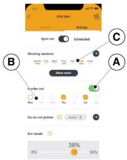
4.7.10. BORDER CUT
The "Border cut" section allows to program the border cutting of the garden on a certain day.
- Press the selector (A) to enable the function.
- Choose the days on which to cut the border (B).
NOTE: The border cut can be activated only for the days of the week in which the robot lawn mower has been programmed to work (C).
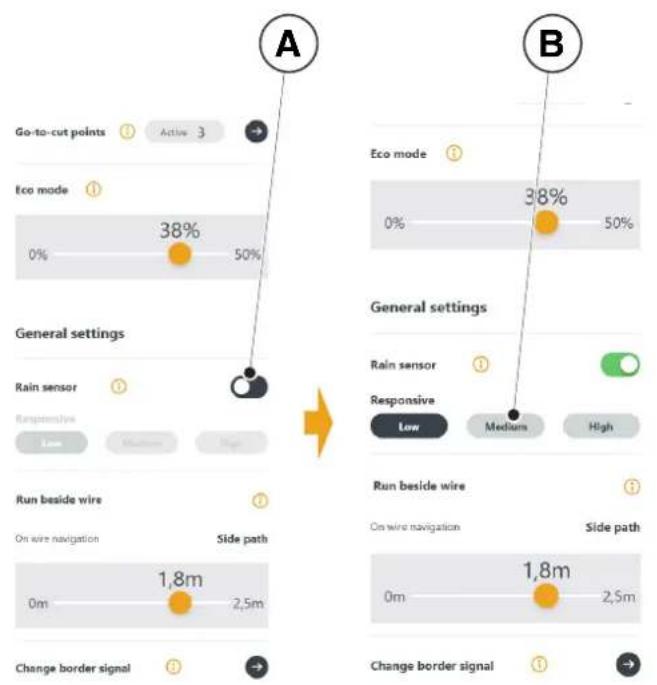
4.7.11. ECO MODE
NOTE: Check the availability of this function on the STIGA.GO App.
The "Eco mode" function (A) allows to set a low power consumption mode reducing, in percentage, the working time of the robot lawn mower compared to the programming performed by the user (B).
NOTE: It is advisable to use this function at times of the year when the grass grows more slowly.

4.7.12. RAIN SENSOR
The "Rain sensor" function allows you to enable or disable the rain sensor on the robot lawn mower.
- Press the selector (A) to enable the function.
- Choose from the three available rain sensor sensitivity levels (B).
4.7.13. USER MANAGEMENT
NOTE: Check the availability of this function on the STIGA.GO App.
The main user who performed the first registration of the product can invite other users to manage the robot lawn mower through the procedure accessible from the button (A).
NOTE: The added users can always be viewed and managed from the menu (A).
NOTE: The invited user must download the App on their mobile device and must register.
4.7.14. DEALER
The "Dealer" section allows to choose the reference service centre.
- Pressing the button (A) the page (B) is accessed from which you can select your reference Dealer from a list. (C).


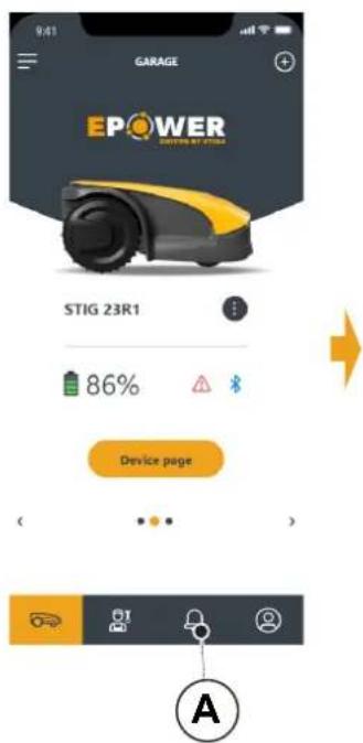
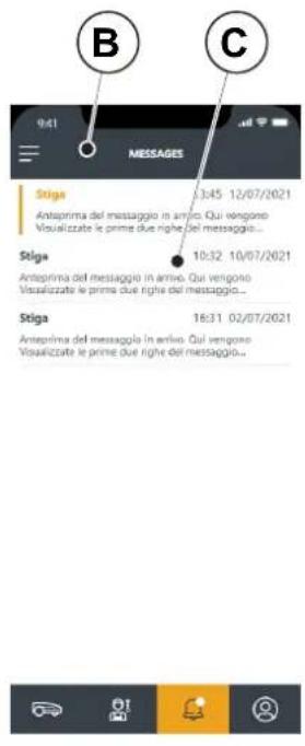
4.7.15. MESSAGES
The "Messages" section displays messages\information.
- By pressing button (A) you access page (B) from which you can view any messages \ information (C) from STIGA intended for the user.
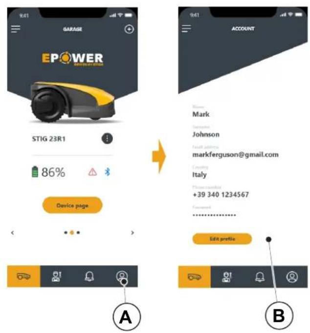
4.7.16.PROFILE
The "Profile" section (A) allows to access the user profile, from which the user can modify the account data and change the password (B).
5. OPERATION
Requirements and obligations:
- Installation completed according to instructions (See Chap.4)
- Programming the robot lawn mower according to the instructions (see Par. 4.7 for automatic operation)
- Powered charging base - Initial grass height in the range of operation of the robot lawn mower: 20-60 mm
- Battery charged (see Par. 5.5) • Properly adjusted cutting height (see Par. 5.6).
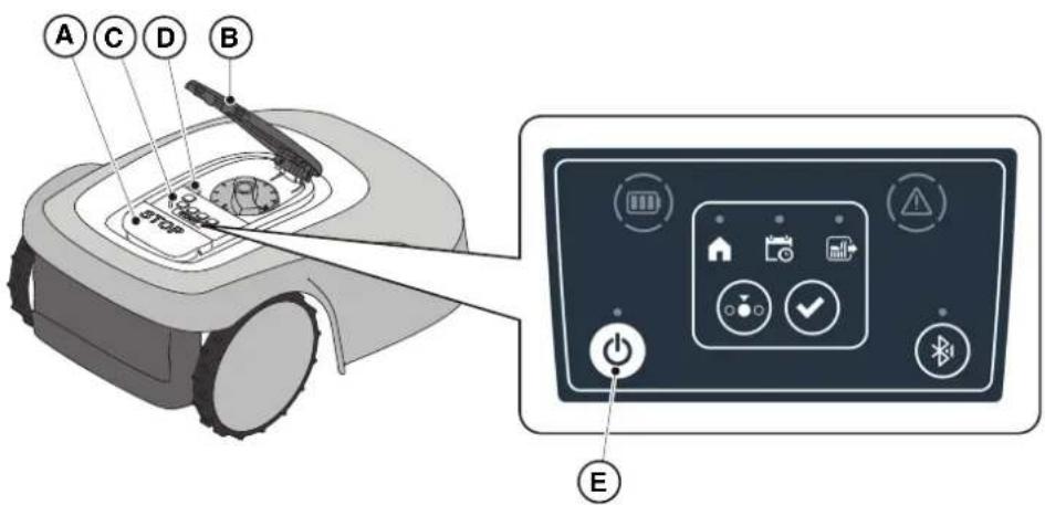
5.1. CHECK OF SAFETY DEVICES FOR STARTING THE ROBOT LAWN MOWER
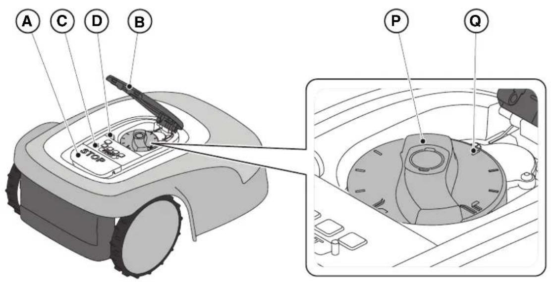
Requirements and obligations:
Procedure:
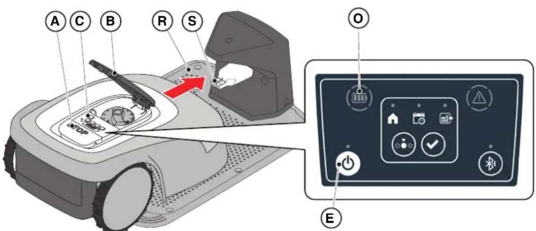
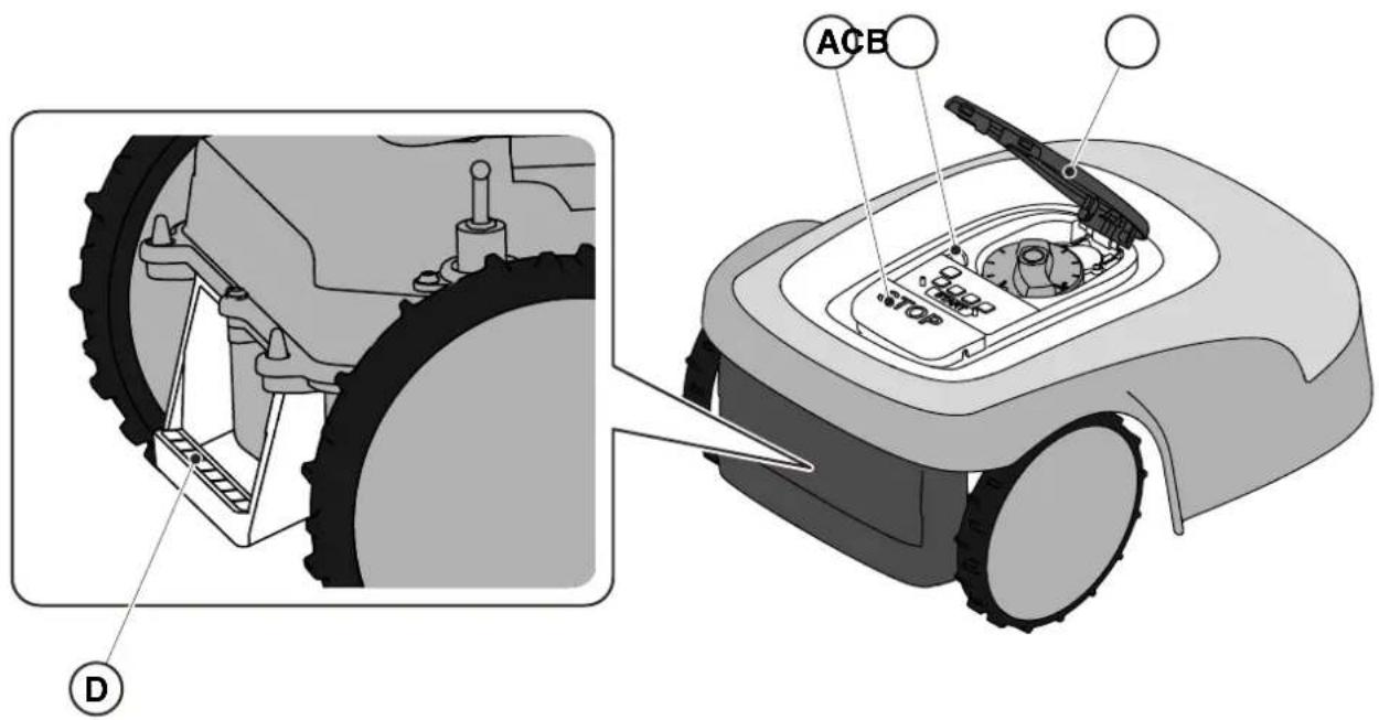
- Check that the floating cover (A) is fitted correctly. If the cover is missing the robot lawn mower doesn't work.
- Check that the safety key (E) is inserted If it is not inserted the robot lawn mower doesn't start.
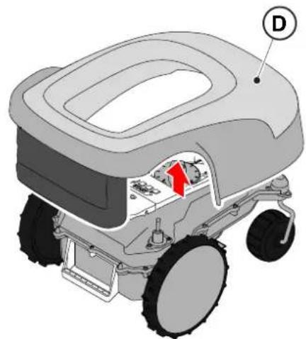
- Check that the stop button "STOP" (B) is not active. If pressed, it stops the robot lawn mower and opens the protective cover (C) of the control console (D).
- Check that the robot lawn mower is positioned on the ground correctly. In case of excessive tilt (≥ 45%) or lift, the tilt sensors (inclinometer) stop the robot lawn mower.
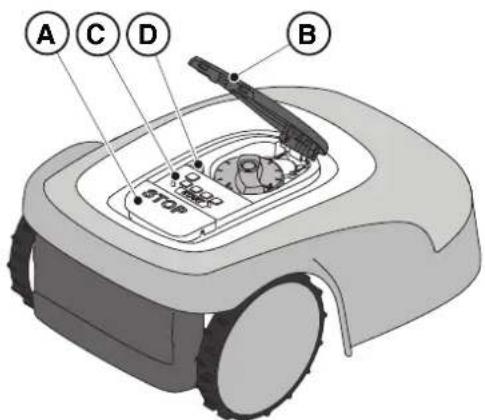
5.2. MANUAL FUNCTIONING OF THE ROBOT LAWN MOWER
The robot lawn mower can be used without performing the programming procedure described in Par. 4.7. In this mode the robot lawn mower carries out a work cycle, returns to the charging base and remains there until the next manual start.
Procedure:
- Place the robot mower on the charging base or within the perimeter of the installation.
- Press the "STOP" button (A) to open the cover (B) and access the control console (C).
- Press the "ON/OFF" button (E) for 3 seconds to switch on the robot lawn mower.
- Press the "SELECT MODE" button (F) until only the icon (L) flashes.
- Press the "CONFIRM" push button (G). The icon (L) lights up with a steady light to confirm the operation.
- Close the cover (B).
- The robot lawn mower will start operating.
NOTE: This mode may not guarantee adequate coverage of the garden, both in terms of time required and in terms of uniformity of the cutting result, especially if the garden has an irregular shape. To achieve the maximum efficiency of the robot lawn mower, it is recommended to carry out programming (see Par. 4.7).
NOTE: If after pressing the "CONFIRM" button (G), the "SELECT MODE" button (F) is pressed, the icons for the selected functions will start fl ashing again, requesting confirmation of the newly selected function. Press the "CONFIRM" button (G). The icons will once again light up with a steady glow.
NOTE: If the cover (B) is opened, either during work or with the robot in the base, the icons relating to the selected functions will flash, to indicate that it is necessary to confirm the operation before closing the cover again. If the cover is closed without pressing the The "CONFIRM" button (G), the robot will not perform any operation until a new command is given by the user.
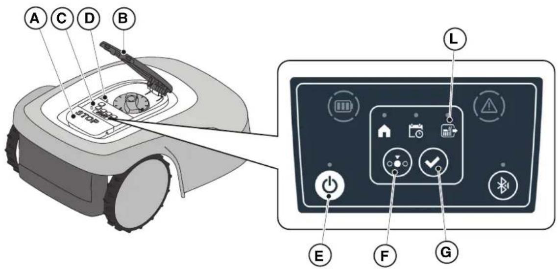
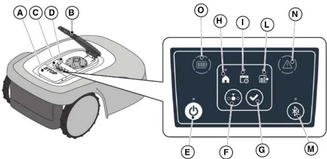
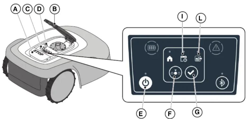
5.3. DESCRIPTION OF THE CONTROLS ON THE ROBOT LAWN MOWER
List of controls, indicators and their function:
- The "STOP" button (A): is used to safely stop the robot mower.
- The "SAFETY KEY" (D): is used for the safety shut-down of the robot lawn mower.
- The "ON/OFF" button (E): is used to turn the robot lawn mower on and off and resetting the alarms.
- The "MODE SELECTION" button (F): is used to select the operating mode of the robot lawn mower and to force it to return to the charging base.
- The "CONFIRM" button (G): is used to confirm the operating mode set.
- The "SCHEDULED PROGRAM" light icon (I): is used to display the scheduled program settings.
- The "SINGLE WORK CYCLE" light icon (.L): is used to display the single work cycle settings.
- The "RETURN TO BASE" light icon (H): is used to display the forced return-to-base setting of the robot lawn mower.
- The "BLUETOOTH" button (H): is used to display the bluetooth status and disconnection.
- The "ALARM" light icon (I): is used to display the alarms status.
- The "BATTERY" light icon (F): is used to display the battery charging.
The "STOP" button (A) is a control that stops the robot lawn mower in safety conditions, whatever its operating condition is.
Procedure:
- Press the "STOP" button (A) while the robot lawn mower is moving or already still.
- When the "STOP" button (A) is pressed, the robot lawn mower stops and the cover (B) opens, allowing access to the other robot controls.
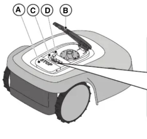
5.3.2. SAFE SHUTDOWN - SAFETY KEY
The safety key (D), by switching off, allows the robot lawn mower to be switched off safely.

OBLIGATION:
Always remove the safety key before any operation of cutting height adjustment, cleaning, transport and maintenance
Procedure:
- Press the button "STOP" (A) to open the cover (B) and access the control console (C).
- Remove the safety key (D) and keep it in a safe place.
- After carrying out the maintenance operations, insert the safety key to be able to switch on the robot lawn mower.
The "ON / OFF" button (E) allows to switch the robot lawn mower on and off manually.
Procedure:
- Press the button "STOP" (A) to open the cover (B) and access the control console (C).
- Press the "ON/OFF" button (E) for 3 seconds to switch on the robot lawn mower or to switch it off.
NOTE: To switch on the robot lawn mower, the safety key (D) must be inserted.
NOTE: Removing the safety key (D) shuts down the robot lawn mower, even if it was not previously switched off using the "ON / OFF" button.
NOTE: In case of active alarms, a double press of the "ON/OFF" button will reset the alarms.
The "MODE SELECTION" button is used to activate or deactivate the set work program via the App and to select the forced return to the charging base. The robot lawn mower operates according to the possible selections described below.
KEYBOARD SELECTIONS AND ROBOT OPERATION
SCHEDULED PROGRAM
The robot lawn mower operates according to the programming set via the app.
RETURN TO BASE + SCHEDULED PROGRAM
The robot lawn mower returns to the charging base. The robot lawn mower will resume working from the following set start time.
SINGLE WORK CYCLE + SCHEDULED PROGRAM
The robot lawn mower performs a single forced work cycle and returns to the charging base when finished. The robot lawn mower will resume working from the following set start time.
SINGLE WORK CYCLE
The robot lawn mower performs a single forced work cycle and returns to the charging base.
The robot lawn mower stays in the base until the user intervenes manually.
RETURN TO BASE + SINGLE WORK CYCLE
The robot lawn mower returns to the charging base. The robot lawn mower stays in the base until the user intervenes manually.


Procedure:
- Press the "STOP" button (A) to open the cover (B) and access the control console (C).
- Press the "MODE SELECT" button (F) until the icons of the functions you wish to activate flash. The icons relating to the selected functions flash.
- Press the "CONFIRM" push button (G). The icons of the selected functions light up steadily to confirm the action.
- Close the cover (B).
- The robot lawn mower will start working according to the set mode.
NOTE: If after pressing the "CONFIRM" button (G), the "SELECT MODE" button (F) is pressed, the icons for the selected functions will start flashing again, requesting to confirm the newly selected function. Press the "CONFIRM" button (G). The icons return to a steady light.
NOTE: If the cover (B) is opened, either during work or with the robot in the base, the icons relating to the selected functions will flash, to indicate that it is necessary to confirm the operation before closing the cover again. If the cover is closed without pressing the "CONFIRM" button (G), the robot will not perform any task until a new command is given by the user.
NOTE: If the robot battery is low, the battery icon fl ashes red to indicate that the selected action cannot be performed.
NOTE: the robot lawn mower starts only after closing the cover (B).
NOTE: The robot lawn mower goes to the charging base with the cutting device switched off.
NOTE: The robot lawn mower can be used in "SINGLE WORK CYCLE" mode even without programming the working hours via the App. This mode may not guarantee adequate coverage of the garden, both in terms of time required and in terms of uniformity of the cutting result, especially if the garden has an irregular shape. To achieve the maximum efficiency of the robot lawn mower, it is recommended to carry out programming (see par. 4.7).
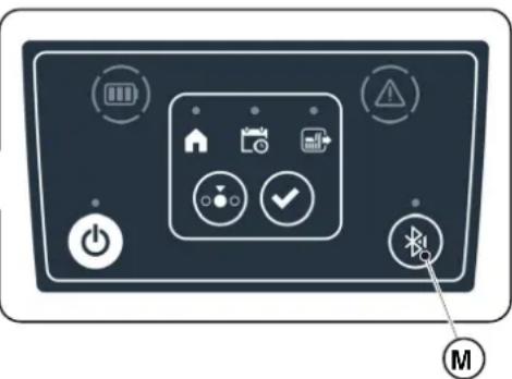
- Flashes if the robot lawn mower is ready to pair.
- It is lit with a steady light if the robot lawn mower is connected to a mobile device.
The robot lawn mower automatically disconnects from the device when the app is closed.
The button (M) is used to disconnect the robot lawn mower in the event that the app of a second user is unintentionally connected to the robot lawn mower.
Procedure:
- Press the button "STOP" (A) to open the cover (B) and access the control console (C).
- To disconnect the robot lawn mower from a mobile device, press and hold the (M) button for 3 seconds.
NOTE: For pairing the device with the robot lawn mower via Bluetooth, see (Par. 4.7.3 Pairing).
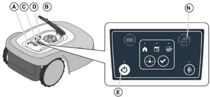
5.3.6. DISPLAY OF ALARM STATES-ALARM ICON
The luminous "ALARM" icon (N) indicates an operating anomaly.
Procedure:
- Press the button "STOP" (A) to open the cover (B) and access the control console (C).
-
Check the alarm status using the light icon (N):
-
Green icon: indicates presence of special operational information;
- Yellow icon: indicates minor abnormalities;
-
Red icon: indicates serious anomalies or malfunctions that may require assistance from the service centre.
-
After resolving the fault, press the "ON/OFF" button (E) twice in rapid succession to reset the alarm. The light icon (N) goes out, and the robot lawn mower can be restarted. If the icon (N) does not go off, remove the safety key (D), wait a few seconds and then switch the robot lawn mower on again using the "ON/OFF" button (E). If the problem persists, contact a service centre.
NOTE: Details of operational information or anomalies can be viewed on the App.
5.3.7. BATTERY CHARGE DISPLAY-BATTERY ICON
The bright "BATTERY" icon (O) displays the battery charging status.
Procedure:
- Press the button "STOP" (A) to open the cover (B) and access the control console (C).
-
Check the battery charging status using the light icon (O):
-
Blue icon: the battery is charged.
- Red icon: the battery is low.
- If the mower robot is charging, the light icon (O) flashes.
NOTE: if the battery icon (O) fl ashes rapidly red when a command is pressed, the operation cannot be carried out and it will be necessary to charge the battery manually (see Par. 5.5).
5.3.8. STARTING THE ROBOT LAWN MOWER
To start up the robot lawn mower, follow the procedure described in Par. 5.3.4 "SCHEDULED PROGRAM SELECTION / SINGLE WORK CYCLE / FORCED RETURN TO CHARGING BASE - MODE SELECTION BUTTON".
5.4. FUNCTIONING OF THE CHARGING BASE
The charging base is provided with a warning light (N) that lights up as follows:
- Warning light off : the charging base is powered off or the robot is on the base;
- Fixed warning light: the perimeter cable is correctly connected to the charging base, and the perimeter signal is correctly transmitted;
- Indicator light flashing slowly: the perimeter cable is not connected or is interrupted (the perimeter cable integrity check is not performed continuously, but only when the robot leaves the charging base or the base is powered);
- Warning light flashing quickly: the perimeter cable is too short (see Par. 4.5.4) or there is a fault in the charging base.
5.5. BATTERY CHARGING
The "BATTERY CHARGING" procedure allows to recharge the robot lawn mower manually. Requirements and obligations:
- Charging base connected to the mains.
Procedure:
- Position the robot lawn mower on the charging base (R).
- Slide the robot lawn mower onto the charging base, until the charging connector (S) is engaged.
- Press the button "STOP" (A) to open the cover (B) and access the control console (C).
- Turn the robot lawn mower on with the "ON/OFF" button (E).
- When the "BATTERY" icon (O) flashes blue, the robot lawn mower is charging.
- Close the cover (B).
- Leave the robot lawn mower to charge for at least the time shown in Par. 4.5.3.
NOTE: Charging the battery before winter storage should be carried out as reported in Par. 6.4.
5.6. CUTTING HEIGHT ADJUSTMENT
The "CUTTING HEIGHT ADJUSTMENT" procedure describes how to adjust the height of the cutting blades.
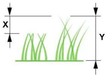
- The length X of grass cut by the robot lawn mower must not exceed 10mm.
- The robot lawn mower's operating range is 20 - 60mm (cutting height).
- The initial height of the grass Y must therefore be 70 mm maximum.
At the first installation or at the beginning of the mowing season, if necessary, prepare the garden with a traditional lawn mower to bring the initial height of the grass to an appropriate value.
NOTE: If you want to cut the grass more than 10mm , adjust the cutting height so that the cut grass part is 10mm . Lower the cutting height further only after the garden has been mowed evenly.
Procedure:
- Press the button "STOP" (A) to open the cover (B) and access the control console (C).
- Remove the safety key (D).
- Use the height adjuster (P) to select the desired cutting height so that the cut grass part is no more than 1 cm.
- Insert the safety key (D).
NOTE: On the knob there is a scale graduated from 1 to 10 (Q) to be used as a reference.
6. MAINTENANCE
6.1. SCHEDULED MAINTENANCE

CAUTION: Only use original spare parts.

CAUTION: Do not modify, tamper with, elude or eliminate the safety devices installed.
For a better operation and longer life, be sure to clean the product regularly and replace worn parts.
Perform the interventions following the frequency indicated in the table.
| FREQUENCY COMPONENT | TYPE OF INTERVENTION REFERENCE | | |
| Weekly Blade Clean and check blade | efficiency | (See Par. 6.2) | |
| If the blade is bent due to impact or if it's worn, replace it. | (See Par. 6.3) | |
| Recharging contacts | Clean and eliminate any oxidising. | (See Par. 6.2) |
| Monthly Robot lawn mower | Carry out cleaning. | (See Par. 6.2) | |
| Charging base and power cables | Check for wear or deterioration and replace if necessary. | (Contact an authorised service centre) |
| At the end of the mowing season or every six months if the robot lawn mower is not used | Battery Perform the | pre-storage charging of the battery. | (See Par. 6.4) |
| Annual or at the end of the cutting season | Robot lawn mower | Carry out the servicing at an authorized service centre. | (See Par. 6.1) |
It is necessary to carry out a maintenance servicing annually at an authorized service centre to keep the robot lawn mower in good working conditions.
The servicing provides for a series of verifications including:
- The internal and external cleaning of the robot lawn mower;
- the general check of the status of the robot lawn mower;
the replacement of worn parts;
- the checking of the battery status;
- the verification of tightening torques;
- the verification and possible replacement of the impact and lifting kinematic mechanisms and their protective bellows;
- the check and, if necessary, replacement of the rubber bellows protecting the blade motor, to maintain the protection specifications against water infiltrations;
- the replacement of the sealing gaskets of the bodies and the battery compartment to maintain the specifications of protection against water infiltrations.
NOTE: any malfunction due to not having carried out the annual servicing will not be recognized under warranty.
6.2.PRODUCT CLEANING

CAUTION: Danger of cutting hands.

CAUTION: Danger of dust in the eyes.
Requirements and obligations:
- Sponge • Dry cloth
- Neutral soap - Gloves
- Brush - Glasses
Water

GLOVES OBLIGATION: Use protective gloves to avoid cutting your hands.

GLASSES OBLIGATION: Use safety glasses to avoid the danger of dust in the eyes.
Procedure:
- Press the "STOP" (A) button to stop the robot lawn mower and open the protective cover (B).
- Remove the safety key (C).
- Remove the floating cover (D) to make the cleaning easier.
- Clean all the external surfaces of the robot lawn mower with a sponge dampened in lukewarm water and neutral soap.

WARNING: Too much water can filter in and damage electrical parts.

WARNING: Do not modify, tamper with, elude or eliminate the safety devices installed.

BAN: Do not use pressurized water jets.

BAN:
To avoid irreversible damage to the electrical and electronic components, do not immerse the robot lawn mower, partially or completely, in water.

BAN:
Do not wash the internal parts of the robot lawn mower to avoid damaging the electrical and electronic components.

BAN:
Do not use solvents or petrol so as not to damage varnished surfaces and plastic parts.
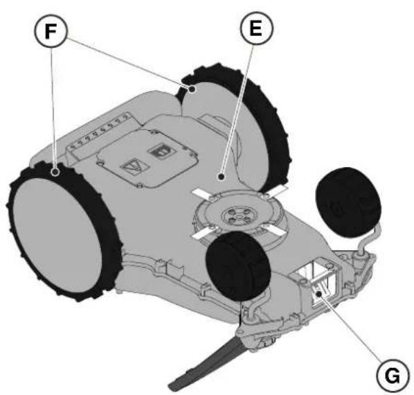
- Remove mud and dirt from the drive wheels (F).
- Clean the underside (E) of the robot lawn mower (cutting blade area, front and rear wheels). Use a suitable brush to remove encrustations and / or debris that could prevent the robot lawn mower from working properly. Complete the cleaning with a damp sponge.
- Clean the battery charging connector (G).
- Clean the charging base (H) and the contact connector (I) from accumulated residues.
6.3. REPLACEMENT OF THE CUTTING BLADES

CAUTION: Danger of cutting hands.
Requirements and obligations:
- Safety key - Key
Cutting blades · Gloves

GLOVES OBLIGATION: Use protective gloves to avoid cutting your hands.
Procedure:
- Press the "STOP" (A) button to stop the robot lawn mower and open the protective cover (B).
- Remove the safety key (C).
- Turn the robot lawn mower upside down, taking care not to damage the floating cover.
- Unscrew the fixing screws (E).
- Replace the cutting blades (D).
- Unscrew the fixing screws (E).

6.4. WINTER BATTERY MAINTENANCE AND STORAGE
Procedure:
- Charge the battery according to the guided procedure in the App, accessible from the "Settings" page.
- Clean the robot lawn mower (see Par. 6.2).
- Check the robot lawn mower is switched off and store in a dry place, protected from icy conditions.
- The battery must be recharged every 6 months and, in any case, before winter storage.
NOTE: The guided procedure registers the successful recharging of the battery in the cloud, and is to be considered completed if the date of the winter pre-storage recharge is updated.
NOTE: Registering the charge through the app procedure is required for the battery warranty to be valid.
NOTE: The battery must be recharged every 6 months and, in any case, before winter storage.
6.5. BATTERY REPLACEMENT
Battery replacement is the sole responsibility of the STIGA TECHNICAL ASSISTANCE STAFF. If the battery needs to be replaced, contact a service centre or your retailer.
7. TROUBLESHOOTING

CAUTION:
Stop the robot lawn mower and bring it back to safety conditions (See Par. 5.3.2).
Below there is the list of any anomalies that may arise during the work phase.
| PROBLEM CAUSES | SOLUTIONS | |
| Abnormal vibrations.The robot lawn mower is noisy. | Damaged cutting disc or blades Replace the damaged components(see Par. 6.3). |
| Cutting device blocked by residues (tapes, ropes, plastic fragments, etc.). | Switch off the robot lawn mower in safety conditions (see Par. 2.3). Unlock the cutting blade. |
| The robot lawn mower was started in the presence of unexpected obstacles (fallen branches, forgotten objects, etc.). | Switch off the robot lawn mower in safety conditions (see Par. 2.3). Remove obstacles and restart the robot lawn mower(see Par. 5.3.9). |
| Electric motor failure Replace the motor, contact the nearest authorized service centre. |
| Grass too tall Increase the cutting height (see Par. 5.6). |
| Make a preliminary cut of the area with a normal lawn mower (see Par. 5.6). |
| The robot lawn mower does not position itself properly inside the charging station. | Incorrect position of the perimeter cable. | Check the connection of the charging station (see Par. 4.5.13). |
| Ground next to the recharging base has collapsed | Restore the correct positioning of the charging base. (See Par. 4.5.3). |
| The mower robot behaves abnormally around perimeter obstacles. | Perimeter cable laid in the wrong way | Reposition the perimeter cable correctly (clockwise) (see Par. 4.5.1). |
| The robot lawn mower works at the wrong times. | Clock set in the wrong way Reset the robot lawn mower clock(see Par. 4.7.6). |
| Working time set incorrectly Reset the working time (see Par. 4.7.8). |
| PROBLEM CAUSES SOLUTIONS | |
| The working area is not mowed completely. | Insufficient working hours. Extend working hours (see Par. 4.7.8). |
| Cutting device with encrustations and / or residues. | Switch off the robot lawn mower in safety conditions (see Par. 2.3). Clean the cutting device. |
| Pivoting cutting blades blocked by encrustations or residues. | Switch off the robot lawn mower in safety conditions (see Par. 2.3). Replace the cutting blades. |
| The working area is too large for the robot lawn mower's capacity. | Reduce the work area (see Technical Data Par. 1.2). |
| Batteries about to exhaust their life cycle. | Replace batteries with original spare parts (see Par. 6.5) |
| Batteries are not charged completely. | Clean and eliminate any oxidation from the contact points (See Par. 6.2). Recharge the batteries. |
| Parts of the garden not completely mowed. | Wrong cut point programming. Correctly program the secondary cut points correctly (see Par. 4.7.9). |
| The charging base light does not turn on when the robot is out of the charging base. | The supply voltage is missing or there is a fault in the charging base. | Check that the power supply unit is plugged in correctly. Check the integrity of the power supply connection cable. |
| The charging base light turns on slowly | The perimeter cable is not connected or is broken | Check the installation and repair the break (see Par. 4.5.2) |
| The charging base light turns on with quick flashing | the perimeter cable is too short or there is a fault in the charging base. | Check that the length of the perimeter cable is greater than indicated in Par. 4.5.1. If necessary, install the resistor (See Par. 4.5.4). If the problem persists, contact a service centre. |
| The warning icon is on on the keyboard | It indicates anomaly / failure conditions. | See the app for more information or contact a service centre. |
7.1. MAIN MESSAGES FROM APP
| PROBLEM CAUSES SOLUTIONS | | |
| “No Signal” appears on the App while the robot lawn mower is inside the perimeter and the LED transmitter in the charging base is on. | The robot lawn mower has a problem in receiving the signal. | Contact an authorized service centre. |
| PROBLEM CAUSES | SOLUTIONS | |
| "Out of perimeter" appears on the app. | Ground slopes too much Delimit the way | area with excessive slope (see Par. 4.3) |
| Perimeter cable laid in the wrong way | Check that the cable is installed correctly (excessive depth, proximity to metal objects, distance between the cable that delimits two elements, etc.). (See Par. 4.5.1). |
| Perimeter cable for delimiting internal areas (flower beds, bushes, etc.) incorrectly laid. | Reposition the perimeter cable correctly (go around the obstacle in the same direction of travel of the perimeter.) (See Par. 4.5.1). |
| Overheated power supply unit. Adopt suitable solutions to reduce power supply unit temperature (air or modify installation area, etc.) (see Par. 4.3) |
| "Lifted Robot" appears on the App | The robot lawn mower is lifted from the ground. | Check that the robot lawn mower is not blocked or obstructed by any objects. Clean and remove any grass residues under the hood that may obstruct the sensors (See Par. 6.2). |
| "Wheel error" appears on the app. | Uneven ground or with obstacles stopping the movement. | Check that the lawn to be mowed is uniform with no holes, stones or other obstacles. If it's not, carry out the necessary environmental decontamination operations (see Par. 4.3). |
| One or both motors working the wheel drive have failed | Replace the motor, contact the nearest authorized service centre. |
| The app displays "Tall Grass" or "Mowing Error". | Blocked or damaged cutting disc. | Stop the robot lawn mower in safety conditions (see Par. 2.3). Release the cutting disc from objects that cause it to block or replace the cutting disc with a new one (see Par. 6.3). |
| Pivoting cutting blades worn or blocked by encrustations or residues. | Switch off the robot lawn mower in safety conditions (see Par. 2.3). Unblock and clean or replace the cutting blades (see Par. 6.3). |
| The robot lawn mower was started in the presence of unexpected obstacles (fallen branches, forgotten objects, etc.). | Switch off the robot lawn mower in safety conditions (see Par. 2.3). Remove the obstacles and restart the robot lawn mower. |
| Electric motor failure Replace the motor, contact the nearest authorized service centre. |
| Grass too tall Increase the cutting height (see Par. 5.6). Make a perimeter cut. |
| The App displays "Tipping". | The robot lawn mower is on a slope that is higher than the allowed limits. | Exclude the area with the slope beyond the allowed limits by delimiting it (see Par. 4.3) |
8. TRANSPORT, STORAGE AND DISPOSAL
8.1. TRANSPORT
Procedure:
NOTE: We recommend using the original packaging for transport over long distances.
- Press the "STOP" (A) button to stop the robot lawn mower and open the protective cover (B).
- Remove the safety key (C).
- Clean the robot lawn mower as indicated in Par. 6.2 "PRODUCT CLEANING".
- Lift the robot lawn mower by the handle (D) and carry it, taking care to keep the cutting blade away from the body.
- Reposition the robot lawn mower in its original packaging.
8.2. STORAGE
The robot lawn mower must be stored in a dry and frost-free place after having completed the cleaning process and the recharging of the battery for winter. (see Chap. 6).
8.3.DISPOSAL

WARNING:
To remove the battery from the robot lawn mower, contact an authorized service centre.
Procedure:
- Dispos of the product packaging in a sustainable way in the appropriate collection containers or at special centres authorized for collection.
- Dispos of the robot lawn mower in accordance with local legal requirements.
- Contact appropriate facilities for recycling and disposal as the robot lawn mower is classified as WEEE (Waste Electrical and Electronic Equipment).
- Dispos of old or used batteries in a sustainable way in collection containers or at authorized collection centres
9. ACCESSORIES
| Art. number | Description Specifications | |
| 1127-0009-01 | Cutting blades 12 pcs | |
| 1127-0011-01 | Docking station cover For additional protection against rain and sunlight | |
| 1127-0010-01 | Cable extension for charger Cable to extend the connection between the power supply and the docking station - L = 5 m | |
| 1127-0012-01 | Installation KIT Small Perimeter cable Ø 2,7 mm - L = 150 m + 200 fixing pegs + 5 cable connectors + 5 docking station cable connectors | |
| 1127-0013-01 | Installation KIT Medium Perimeter cable Ø 2,7 mm - L = 300 m + 400 fixing pegs + 5 cable connectors + 5 docking station cable connectors | |
| 1127-0000-01 | Cable reel 150 m Perimeter cable Ø 2,7 mm - L = 150 m | |
| 1127-0001-01 | Cable reel 300 m Perimeter cable Ø 2,7 mm - L = 300 m | |
| 1127-0002-01 | Cable reel 500 m Perimeter cable Ø 3,4 mm - L = 500 m | |
| 1127-0006-01 | Fixing pegs (100 pcs) Pegs to fix the perimeter cable - 100 pcs | |
| 1127-0008-01 | Docking station fixing pegs 8 pcs | |
| 1127-0004-01 | Cable connectors Joints for the repairing of the perimeter wire-5 pcs | |
| 1127-0005-01 | Docking station cable connectors | Connectors to connect the perimeter wire to the docking station - 5 pcs |
| 122063053/0 | Small garden resistor | Resistor for installations with less than 40 m of perimeter cable |
10. WARRANTY
The warranty conditions are intended for consumers only, i.e. non-professional operators.
The warranty covers all material quality and manufacturing defects recognised during the warranty period by your Dealer or Authorised Service Centre.
The warranty is restricted to the repair or replacement of components recognised as faulty.
It is advisable to send your machine once a year to an authorized service workshop for servicing, assistance and safety device inspection.
The warranty only applies to machines subjected to regular maintenance.
The warranty does not cover damages resulting from:
- Failure to become familiar with the documentation accompanying the machine (Instruction manuals).
Professional use.
- Carelessness, negligence.
- External causes (lightning, impact, presence of foreign bodies inside the machine) or incidents.
Incorrect use or assembly prohibited by the manufacturer
- Poor maintenance.
- Modification to the machine.
- Use of non-genuine spare parts (adaptable parts).
- Use of accessories not supplied or approved by the manufacturer (e.g. cutting devices).
The warranty does not cover:
- Maintenance operations (described in the instruction manual).
- Normal wear of consumables such as cutting devices and wheels.
Normal wear and tear.
- Deterioration in the appearance of the machine due to use.
- Cutting means supports.
- Damage resulting from an installation that does not comply with the user manual.
- Any corrosion or damage to the perimeter cable.
- Damage caused by water infiltration due to the use of a high pressure washing device or by immersion in water, for example when puddles of water form from heavy rain.
- Damage caused by improper storage or improper use of the battery.
- Damage caused by using non-original batteries.
- Any additional cost possibly connected to the repair under warranty, such as moving the machine to the user's premises, bringing the machine to the Dealer, hiring equipment or contracting other companies for any garden maintenance work while the machine is out of service.
The user is protected by his or her own national legislation. The user's rights under the national laws or his or her own country are not in any way restricted by this warranty.
| a) Tipo Modelo Base
b) Mese_Anno di costruzione
c) Matricola
d) Motore | SRSW01
Batteria | SRSW01
e) Month_Year of manufacture
f) Serial Number
d) Motor | SRSW01
e) Approved Body: Not Applicable
f) Type-examination: Not Applicable
d) Battery operated | SRSW01
e) S.I. 2008/1597 - Supply of Machinery (Safety) Regulations 2008
e) S.I. 2017/1206 - The Radio Equipment Regulation 2016
S.I. 2016/1091 - Electromagnetic Compatibility Regulations 2016 |
STIGALTD (UK Importer)
Unit 8, Bluewater Estate Plympton,
Devon, PL7 4JH, England
STIGAS.p.A.
Via del lavoro, 6
31033 Castelfranco Veneto (TV)
Italy
/TIGA
Stig 300
Stig 600
Stig 1200

Status: On
Mowing Mode: I'm mowing
All sessions


Cutting closed area


Go to Jing stnep


4.7.5. ZONE FERMÉE (CLOSED AREA)
4.7.8. SESSIONS DETONTE (MOWING SESSIONS)
m = 311


5. FONCTIONNEMENT
| a) Tipo Modelo Base
b) Mese_Anno di costruzione
c) Matricola
d) Motore | SRSW01
Batteria | SRSW01
e) Month_Year of manufacture
f) Serial Number
d) Motor | SRSW01
Not Applicable
Type-examination: Not Applicable
S.I. 2017/1206 - The Radio Equipment Regulation 2016
S.I. 2016/1091 - Electromagnetic Compatibility Regulations 2016
S.I. 2012/3032 - The Restrictions of the Use of Certain Hazardous Substances in Electrical and Electronic Equipment Regulations 2012 |
STIGALTD (UK Importer)
Unit 8, Bluewater Estate Plympton,
Devon, PL7 4JH, England
STIGAS.p.A.
Via del lavoro, 6
31033 Castelfranco Veneto (TV)
Italy
/TIGA stig
Stig 300
Stig 600
Stig 1200
| Stig 300 Stig 600 Stig 1200 |
| Border Cut | ✓ | ✓ | ✓ |
| Run Beside Wire | X | ✓ | ✓ |
| Go-To Cut Points | 135 | | |
| Eco Mode | X | X | ✓ |
| Rain Sensor | X | ✓ | ✓ |
| Closed Area | X | X | ✓ |

Status On
Mowing Mode I'm mowing

All sessions


All sessions

Cutting closed area
A
Cutting closed area

Go to the online section


m = 311


del


(二)股东

1
1

m = 1 ;


1

1 + u8 = 1.5

m = 311


m = 311


m = 311

1

13/14

m = 311

m = 311

m = 311


一


12 =

31 + u + 4q = 1 + u + uq dH

12 =

31 + u + 4q = 1 + u + uq dH

m = 311

m = 311

12/14

INT


m = 311 ;


00
01
02
03


on


1

1

m = 311


10

1

(一)股东大会届次


(1)

m = 311

。


m = 311 ;


1 + u7 = 701x

m = 311 ;

m = 311

13/14

m = 311


5. BETRIEB
| a) Tipo Modelo Base
b) Mese_Anno di costruzione
c) Matricola
d) Motore | SRSW01
Batteria | SRSW01
e) Month_Year of manufacture
f) Serial Number
d) Motor | SRSW01
e) Approved Body: Not Applicable
f) Type-examination: Not Applicable
d) Battery operated | SRSW01
e) S.I. 2008/1597 - Supply of Machinery (Safety) Regulations 2008
e) S.I. 2017/1206 - The Radio Equipment Regulation 2016
S.I. 2016/1091 - Electromagnetic Compatibility Regulations 2016 |
STIGALTD (UK Importer)
Unit 8, Bluewater Estate Plympton,
Devon, PL7 4JH, England
STIGAS.p.A.
Via del lavoro, 6
31033 Castelfranco Veneto (TV)
Italy
/TIGA
Stig 300
Stig 600
Stig 1200
| Stig 300 Stig 600 Stig 1200 |
| Border Cut | ✓ | ✓ | ✓ |
| Run Beside Wire | X | ✓ | ✓ |
| Go-To Cut Points | 135 | | |
| Eco Mode | X | X | ✓ |
| Rain Sensor | X | ✓ | ✓ |
| Closed Area | X | X | ✓ |

Status On
Mowing Mode I'm mowing
All sessions

Start spot cut
4.7.5. AREA CHIUSA (CLOSED AREA)
STIGALTD (UK Importer)
Unit 8, Bluewater Estate Plympton,
Devon, PL7 4JH, England
STIGAS.p.A.
Via del lavoro, 6
31033 Castelfranco Veneto (TV)
Italy
/TIGA stig
Stig 300
Stig 600
Stig 1200
7.PROBLEEMOPLOSSEN 54
7.1. BELANGRIJKSTE MELDINGEN VAN DE APP 55
GEVAAR \WAARSCHUWING \ LET OP:
PLAATSING MET HARINGEN

| Stig 300 Stig 600 Stig 1200 |
| Border Cut | ✓ | ✓ | ✓ |
| Run Beside Wire | X | ✓ | ✓ |
| Go-To Cut Points | 135 | | |
| Eco Mode | X | X | ✓ |
| Rain Sensor | X | ✓ | ✓ |
| Closed Area | X | X | ✓ |
INDEX INSTELLINGEN VAN HET PRODUCT
4.7.1. PRE-LOGIN 31
4.7.2. REGISTRATIE (SIGN UP) 31
4.7.3. ASSOCIATIE (PAIRING) 32
4.7.4. PAGINA PRODUCT (DEVICE PAGE) 33
4.7.5. GESLOTEN GEBIED (CLOSED AREA) 33
4.7.6. INSTELLINGEN (SETTINGS) 33
4.7.7. ENKELE MAAIBEURT / GEPLAND MAAIEN (SPOT CUT / SCHEDULED) 34
4.7.8. MAAISESSIES (MOWING SESSIONS) 34
4.7.9. GO-TO-CUT POINTS 35
4.7.10. DE RAND BIJSNIJDEN (BORDER CUT) 36
4.7.11. ECO-MODUS 36
4.7.12. REGENSENSOR (RAIN SENSOR) 36
4.7.13. BEHEER GEBRUKER 37
4.7.14. VERKOPERS (DEALER) 37
4.7.15.MELDINGEN(MESSAGES) 38
4.7.16.PROFIEL(PROFILE) 38
4.7.1. PRE-LOGIN

Status On
Mowing Mode I'm mowing

All ≤ 10

Start spot cut


Go to the voting station


4.7.5.AFGESLOTEN GEBIED (CLOSED AREA)
TERUGKEER NAAR BASIS + GEPLAND PROGRAMMA
STIGALTD (UK Importer)
Unit 8, Bluewater Estate Plympton,
Devon, PL7 4JH, England
STIGAS.p.A.
Via del lavoro, 6
31033 Castelfranco Veneto (TV)
Italy
/TIGA stig
Stig 300
Stig 600
Stig 1200
| Stig 300 Stig 600 Stig 1200 |
| Border Cut | ✓ | ✓ | ✓ |
| Run Beside Wire | X | ✓ | ✓ |
| Go-To Cut Points | 1 3 5 | | |
| Eco Mode | X | X | ✓ |
| Rain Sensor | X | ✓ | ✓ |
| Closed Area | X | X | ✓ |

Status On
Mowing Mode: I'm mowing
All


4.7.5. ÁRÉA CERRADA (CLOSED AREA)
| a) Tipo Modelo Base
b) Mese_Anno di costruzione
c) Matricola
d) Motore | SRSW01
Batteria | SRSW01
e) Month_Year of manufacture
f) Serial Number
d) Motor | SRSW01
Not Applicable
Type-examination: Not Applicable
S.I. 2017/1206 - The Radio Equipment Regulation 2016
S.I. 2016/1091 - Electromagnetic Compatibility Regulations 2016
S.I. 2012/3032 - The Restrictions of the Use of Certain Hazardous Substances in Electrical and Electronic Equipment Regulations 2012 |
STIGALTD (UK Importer)
Unit 8, Bluewater Estate Plympton,
Devon, PL7 4JH, England
STIGAS.p.A.
Via del lavoro, 6
31033 Castelfranco Veneto (TV)
Italy
/TIGA stig
Stig 300
Stig 600
Stig 1200
STIGALTD (UK Importer)
Unit 8, Bluewater Estate Plympton,
Devon, PL7 4JH, England
STIGAS.p.A.
Via del lavoro, 6
31033 Castelfranco Veneto (TV)
Italy
/TIGA stig
Stig 300
Stig 600
Stig 1200
NO Instruksjonsbok
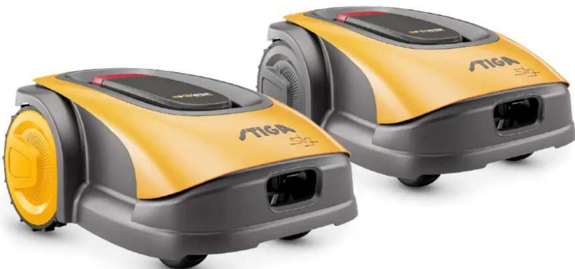
NORSK - OVERSETTALSE AV ORIGINALINSTRUKSJONER
INNHOLD
1. MODELLER OG TEKNISKE OPPLYSNINGER 1
1.1. MODELLER 1
1.2. TEKNISKE OPPLYSNINGER - STIGA STIG 2
2. SIKKERHET 3
2.1. SIKKERHETSINFORMASJON 3
2.2. SIKKERHETSINSTRUKSJONER 5
2.2.1. SIKKER BRUKSPRAKSIS 5
2.2.2. DRIFT 5
2.3. STANS OG AVSKRUING AV ROBOTGRESSKLIPPEREN UNDER SIKRE FORHOLD
3. INTRODUKSJON 8
3.1. GENERELL INTRODUKSJON 8
3.1.1. FORMAL MED HANDBOKEN 8
3.1.2. INSTRUKSJONER FOR LESNING AV INDIKASJONENE PÅ SMARTTELEFON 8
3.2. PRODUKTOVERSIKT 9
3.2.1. GENERELL BESKRIVELSE 9
3.2.2. HOVEDKOMPONENTER 10
3.3.UTPAKKING 11
3.4. SYMBOLER OG SKILT 12
3.5. GENERELLE INSTRUKSJONER FOR LESING AV HANDBOKEN 13
4. INSTALLASJON 14
4.1. GENERELL INSTALLASJONSINFORMASJON 14
4.2. KOMPONENTER FOR INSTALLASJONEN 14
4.3. KONTROLL AV INSTALLASJONSKRAV 15
4.3.1. KONTROLL AV HAGEN: 15
4.3.2. KONTROLLER INSTALLASJONEN AV LADEBASEN OG MATEREN: 15
4.3.3. HOVEDKONTROLLER FOR INSTALLASJON AV KANTLEDNINGEN: 17
4.4. KRITERIER FOR INSTALLASJON AV KANTLEDNINGEN 19
4.4.1. PLASSERING AV KANTLEDNINGEN 19
4.4.2. BEGRENSNING AV HINDRINGENE: 21
4.4.3. PASSASJE MELLOM TRE ULIKE OMRADER I HAGEN 23
4.5. INSTALLASJON AV KOMPONENTENE 23
4.5.1. INSTALLASJON AV KANTLEDNINGEN 24
4.5.2. SKJOTVED KANTLEDNINGEN 25
4.5.3. INSTALLASJON AV LADEBASE 26
4.5.4. INSTALLASJON AV RESISTOR FOR REDUSERTE PARAMETERE 28
4.6. LADING AV ROBOTGRESSKLIPPER ETTER INSTALLASJON 29
4.7. PRODUKTINNSTITINGER 30
5. DRIFT 39
5.1. KONTROLL AV SIKKERHETSENHETENE FOR OPPSTART AV ROBOTGRESSKLIPPEREN 39
5.2. MANUELL DRIFT AV ROBOTGRESSKLIPPEREN 40
5.3. BESKRIVELSE AV KOMMANDOENE SOM FINNES PÅ ROBOTGRESSKLIPPEREN 41
5.3.1. SIKKER STANS - STOPPKNAPP 41
5.3.2. SIKKER AVSKRUING - SIKKERHETSNØKKEL 42
5.3.3. PASKRUING OG AVSKRUING - ON/OFF KNAPP 42
5.3.4. VALG AV PROGRAMMERT KLIPPING / ENKEL KLIPPESYKLUS - KNAPP PLANLAGT PROGRAM 43
5.3.5. VISNING AV BLUETOOTH TILSTAND OG FRAKOBLING - BLUETOOTH KNAPP 45
5.3.6. VISNING AV ALARMTILSTAND - ALARMIKON 45
5.3.7. VISNING AV BATTERIETS LADING - BATTERI-IKON 46
5.3.8 OPPSTART AV ROBOTGRESSKLIPPEREN - STARTKNAPP 46
5.4. DRIFT AV LADEBASE 47
5.5.LADING AV BATTERI 47
5.6.JUSTERING AV KILIPPEHoyDEN 48
6. VEDLIKEHOLD 49
6.1. PLANLAGTVEDLIKEHOLD 49
6.2. RENGJØRING AV PRODUKT 50
6.3. BYTTE AV KLIPPEINNRETNINGENE 52
6.4. VEDLIKEHOLD OM VINTEREN AV BATTERIET OG OPPBEVARING 53
6.5.UTSKIFTNING AV BATTERI 53
7.PROBLEMLØSNING 54
7.1. HOVEDMELDINGER FRA APPEN 55
8. TRANSPORT, OPPBEVARING OG KASSERING 57
8.1. TRANSPORT 57
8.2. OPPBEVARING 57
8.3. KASSERING 57
9. TILBEHØR 58
10.GARANTI 59
10.1.HVA SOM DEKKES AV GARANTIEN 59
11. EU-SAMSVARSERKLAERING 60
1. MODELLER OG TEKNISKE OPPLYSNINGER
1.1. MODELLER
Denne handboken refererer til modellene Stig 300, Stig 600, Stig 1200.
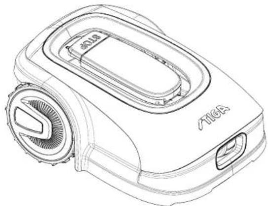

1.2. TEKNISKE OPPLYSNINGER - STIGA STIG
| SPESIFIKASJONER | MÄLE ENHET | STIGA Stig 300 | STIGA Stig 600 | STIGA Stig 1200 |
| Dimensjoner (BxHxD) | [mm] 413 x 252 x 560 413 x 252 x | 560 413 x 252 x 560 | | |
| Robotgresskipperens vekt | [kg] 7.4 7,6 8 | | | |
| Klippehøyde (Min-Maks) | [mm] 20-60 20-60 | 20-60 | | |
| Bladdiameter | [mm] | 180 | 180 | 180 |
| Kuttehastighet | [omdr./min] | 2850+/-50 | 2850+/-50 | 2850+/-50 |
| Fremdriftshastighet | [m/min] | 22 | 22 | 22 |
| Maksimal helling | % | 45 | 45 | 45 |
| Maksimal helling langs omkretsen | % | 20 | 20 | 20 |
| Type elektrisk trekkmotor | - | Brushless | Brushless | Brushless |
| Type klipsystem | - | 4 svingbare klippeblader | 4 svingbare klippeblader | 4 svingbare klippeblader |
| Artikkelnummer for klippeinnretting | - | 322104105/0 | 322104105/0 | 322104105/0 |
| Type elektrisk klippemotor | - | Brushless | Brushless | Brushless |
| Pavist lydeffektnivå | [dB] (A) | 57 | 57 | 57 |
| Usikkerhet om støyutslipp, KWA | [dB] (A) | 1,47 | 1,47 | 1,47 |
| Garantert lydeffektnivå | [dB] (A) | 59 | 59 | 59 |
| Akustisk nivå ved operatoren søre | [dB] (A) | 46,3 | 46,3 | 46,3 |
| Robotgresskipper IP-klassifisering | - | IPX5 | IPX5 | IPX5 |
| IP-klassifisering av ladebasen | - | IPX1 | IPX1 | IPX1 |
| Mater IP-klassifisering | - | IP67 | IP67 | IP67 |
| Omgivelsestemperatur for robotgresskipper [°C] | [°C] | 0 - 50 | 0 - 50 0 - 50 | |
| Omgivelsestemperatur for ladebase [°C] | [°C] | -10 - 50 | -10 - 50 | -10 - 50 |
| Omgivelsestemperatur for materdrift [°C] | [°C] | -10 - 50 | -10 - 50 | -10 - 40 |
| Arbeidskapasitet | [m²] | 300 | 600 | 1200 |
| Strømforsyning | - | Input: 100-240Vac1,2AOutput: 30Vcc 2A | Input: 100-240Vac1,2AOutput: 30Vcc 2A | Input: 100-240Vac1,2AOutput: 30Vcc 2A |
| Batterimodell | - | 25,2 - 25,9 V2 Ah | 25,2 - 25,9 V2,5 Ah | 25,2 - 25,9 V5 Ah |
| Ladetid | [min] | 60 | 80 | 150 |
| Bluetooth | - | 4,2 4,2 | 4,2 | |
2. SIKKERHET
| Stig 300 Stig 600 Stig 1200 |
| Border Cut | ✓ | ✓ | ✓ |
| Run Beside Wire | X | ✓ | ✓ |
| Go-To Cut Points | 135 | | |
| Eco Mode | X | X | ✓ |
| Rain Sensor | X | ✓ | ✓ |
| Closed Area | X | X | ✓ |
INDEKS FOR PRODUKTINNSTILLINGER
4.7.1. FORHANSDINNLOGGING 31
4.7.2. REGISTRERING (SIGN UP) 31
4.7.3.PARING (PAIRING) 32
4.7.4. PRODUKTSIDE (DEVICE PAGE) 33
4.7.5. LUKKET OMRÅDE (CLOSED AREA) 33
4.7.6. INNSTILLINGER (SETTINGS) 33
4.7.7. ENKEL KLIPPING / PLANLAGT KLIPPING (SPOT CUT / SCHEDULED) 34
4.7.8. KILIPPEØKTER (MOWING SESSIONS) 34
4.7.9. GO-TO-CUT POINTS 35
4.7.10. KANTKLIPPING (BORDER CUT) 36
4.7.11. ECO MODE 36
4.7.12. REGNSEROR (RAIN SENSOR) 36
4.7.13. BRUKERSTYRING 37
4.7.14. FORHANDLERE (DEALER) 37
4.7.15.MELDINGER (MESSAGE) 38
4.7.16.PROFIL (PROFILE) 38
4.7.1. FORHÄNDSINNLOGGING
Ved forste gangs innlogging i appen er det mulig:
m = 311


45 12

(1)制片

2018年

1

rate

图1

1


32 10


- 194

W

m = 311

m = 311

2102

del

1.1.1.1

特此公告。


m = 311

m = 311


5. DRIFT
Krav og pabud:
"BLUETOOTH" knappen (M):
6.1. PLANLAGT VEDLIKEHOLD

VARSEL: Bruk kun originale resvedeler.

VARSEL: Ikke tukle med, fjerne, unnvike erer omgå de monterte sikkerhetsanordningene.
EN303447V1.2.0
EN303447V1.2.0
171514280/0
(Supply of Machinery (Safety) Regulations 2008, S.I. 2008 No. 1597, Annex II, part A)
- The Company: ST. S.p.A.-Via del Lavoro, 6-31033 Castelfranco Veneto (TV)-Italy
- Herby declares under its own responsibility that the machine: Robotic lawnmower

- Conforms to UK Regulations:
S.I.2008/1597-Supply of Machinery (Safety) Regulations 2008
e) Approved Body: Not Applicable
f) Type-examination: Not Applicable
S.I. 2017/1206 - The Radio Equipment Regulation 2016
S.J. 2016/1091 - Electromagnetic Compatibility Regulations 2016
S1. 2012/3032 - The Restrictions of the Use of Certain Hazardous Substances in Electrical and Electronic Equipment Regulations 2012
References to Designated by
BIS EN 693251/2012(AC-2014/A11-2014(A13-2017/A1-2019)
2A2019/7/A14/8619
RS ENIEC 63000:2018
BS EN 303 447 V1.2.0
BS EN 50636 107:2015/A1/A2
BS EN 62478:2010
( x - 2x) t - xy^2 = ( x - 2x) f^ t
g) Range of cut: 18 cm
ENLFC63000-2018
EN 60335-1:2012/AC:2014/A11:2014/A13:2017/A1:2019/A2:2019/ EN 55014-1:2017/A11:2020
A14:2019 EN 55014-2:2015
EN IEC 63000:2018 EN 61000-3-2:2019
EN 303 447 V1.2.0 EN 61000-3-3:2013/A1:2019
EN 50636-107:2015/A1/A2 EN 300 328 V2.2
EN 62479:2010 EN 301 489-17 V3.2.4
STIGALTD (UK Importer)
Unit 8, Bluewater Estate Plympton,
Devon, PL7 4JH, England
STIGAS.p.A.
Via del lavoro, 6
31033 Castelfranco Veneto (TV)
Italy
/TIGA stig
Stig 300
Stig 600
Stig 1200
SV Bruksanvisning

SVENSKA - ÖVERSÄTTNING AV ORIGINALINSTRUKTIONERNA
INNEHÄLLSFORTECKNING
1. MODELLER OCH TEKNISKA SPECIFICATIONER 1
1.1. MODELLER 1
1.2. TEKNISKA SPECIFICATIONER - STIGA STIG 2
2. SÄKERHET 3
2.1. SÄKERHETSINFORMATION 3
2.2. SAKERHETSANVISNINGAR 5
2.2.1. SAKRA DRIFTMETODER 5
2.2.2. FUNKTIONSSATTT 5
2.3. STOPPA OCH STÄNGA AV ROBOTGRASKLIPPAREN PÄ ETT SÄKERT SÄTT
3. INTRODUKTION 8
3.1. ALLMÄN INTRODUktion 8
3.1.1. HANDBOKENS SYFTE 8
3.1.2. INSTRUKTIONER FÖR LÄSNING FRÁN SMARTTELEFON 8
3.2. PRODUKTÖVERSIKT 9
3.2.1. ALLMÄN BESKRIVNING 9
3.2.2. HUVUDKOMPONENTER 10
3.3.UPPACKING 11
3.4. SYMBOLER OCH SKYLTAR 12
3.5. ALLMÄNNA INSTRUKTIONER FÖR ATT LÄSA HANDBOKEN 13
4. INSTALLATION 14
4.1. ALLMÄN INFORMATION FÖR INSTALLATIONEN 14
4.2. KOMPONENTER FÖR INSTALLATIONEN 14
4.3. KONTROLL AV INSTALLATIONSKRAVEN 15
4.3.1. KONTROLL AV TRÄDGÄRDEN: 15
4.3.2. KONTROLLER FÖR INSTALLATION AV LADDNINGSBASEN OCH MATAREN: 15
4.3.3. HUVUDKONTROLLER FÖR INSTALLATION AV AVGRÄNSNINGSKABELN: 17
4.4. KRITERIER FÖR INSTALLATION AV AVGÄNSNINGSKABELN 19
4.4.1. PLACERING AV AVGRANSINGSKABELN 19
4.4.2. AVGRANSNING AV HINDER: 21
4.4.3. VAXLA MELLAN OLIKA DELAR AV TRADGARDEN 23
4.5. INSTALLATION AV KOMPONENTER 23
4.5.1. INSTALLATION AV AVGRANNSINGSKABELN 24
4.5.2. SAMMANFOGNING AV OKRETSKABELN 25
4.5.3. INSTALLATION AV LADDNINGSBASEN 26
4.5.4. INSTALLATION AV MOTSTAND FOR SMA OMKRETSAR 28
4.6. LADDNING AV ROBOTGRASKLIPPAREN AFTER INSTALLATION 29
4.7. PRODUKTINSTÄLLNINGAR 30
5. FUNKTIONSSÄTT 39
5.1. KONTROLL AV SÄKERHETSANORDNINGARNA FÖR ATT STARTA ROBOTGRÄSKLIPPAREN......39
5.2. MANUELL FUNKTION AV ROBOTGRÄSKLIPPAREN40
5.3. BESKRIVNING AV REGLAGEN SOM FINNS PÅ ROBOTGRÄSKLIPPPAREN 41
5.3.1. STOPPISAKERHETSLAGE-STOPPKNAPP 41
5.3.2. AVSTÄNGNING I SÄKERHETSLÄGGE - SÄKERHETSNYCKEL 42
5.3.3. PAsTting OCH AVSTANGNING-ON/OFF-KNAPP 42
5.3.4. VAL AV SCHEMALAGT PROGRAM/ENKEL ARBETSCYKEL - KNAPP SCHEMALAGT PROGRAM 43
5.3.5. BLUETOOTH STATUSDISPLAY OCH FRANKOPPLING - BLUETOOTH-KNAPP 45
5.3.6. VISNING AV LARMSTATUS - LARMIKON 45
5.3.7. VISNING AV BATTERILADDNINGEN - BATTERIIKON 46
5.3.8. START AV GRASKLIPPARROBOTEN - STARTKNAPP 46
5.4. ANVÄNDNING AV LADDNINGSBASEN 47
5.5. BATTERILADDNING 47
5.6. REGLERING AV KLIPPHÖJDEN 48
6. UNDERHÄLL 49
6.1. PLAERAT UNDERHÄLL 49
6.2. PRODUKTRENGÖRING 50
6.3.SBYTE AV KLIPPBLAD 52
6.4. UNDERHÄLL OCH LAGRING AV BATTERIET FÖR VINTERN 53
6.5. BATTERIBYTE 53
7. FELSÖKNING 54
7.1. HUVUDMEDDELANDEN FRAN APPEN 55
8. TRANSPORT, LAGRING OCH BORTSKAFFANDE 57
8.1. TRANSPORT 57
8.2. FÖRVARING 57
8.3. BORTSKAFFANDE 57
9. TILLBEHÖR 58
10.GARANTI 59
10.1.GARANTINS TACKING 59
- EG-FÖRSAKRAN OM ÖVERENSSTÄMMELSE 60
1. MODELLER OCH TEKNISKA SPECIFICATIONER
1.1. MODELLER
Den har handboken galler for modellerna Stig 300, Stig 600, Stig 1200.


1.2. TEKNISKA SPECIFICATIONER - STIGA STIG
4.5.2. SAMMANFOGNING AV OMKRETSKABELN.

OBS: Fara for skarsar pahanderna.

| Stig 300 Stig 600 Stig 1200 |
| Border Cut | ✓ | ✓ | ✓ |
| Run Beside Wire | X | ✓ | ✓ |
| Go-To Cut Points | 135 | | |
| Eco Mode | X | X | ✓ |
| Rain Sensor | X | ✓ | ✓ |
| Closed Area | X | X | ✓ |
PRODUKTINSTÄLLNINGSINDEX
4.7.1. FÖRE INLOGGNING 31
4.7.2. REGISTRERING (SIGN UP) 31
4.7.3. SAMMANKOPPLING (PAIRING) 32
4.7.4. PRODUKTSIDA (DEVICE PAGE) 33
4.7.5. STANGT OMRADE (CLOSED AREA) 33
4.7.6. INSTÄLLNINGAR (SETTINGS) 33
4.7.7. ENKEL GRASKLIPPNING/SCHEMALAGD GRASKLIPPNING (SPOT CUT/SCHEDULED) 34
4.7.8. GRASKLIPPSSESSIONER (MOWING SESSIONS) 34
4.7.9. GO-TO-CUT POINTS 35
4.7.10. GRANSSKÄRNING (BORDER CUT) 36
4.7.11. ECO MODE 36
4.7.12. REGNSensor (RAIN SENSOR) 35
4.7.13.ANVANDARHANTERING 37
4.7.14.ATERFORSALJARE (DEALER) 37
4.7.15.MEDDELANDEN(MESSAGES) 38
4.7.16.PROFIL (PROFILE) 38
4.7.1. INLEDNING

Status On
Mowing Mode I'm mowing

All ≤ 10

Start spot cut

Cutting closed area
B

Go to the parking station.
C
D
4.7.5. STÄNGT OMRÄDE (CLOSED AREA)
Knappen "BLUETOOTH" (M):
STIGALTD (UK Importer)
Unit 8, Bluewater Estate Plympton,
Devon, PL7 4JH, England
STIGAS.p.A.
Via del lavoro, 6
31033 Castelfranco Veneto (TV)
Italy
/TIGA stig
Stig 300
Stig 600
Stig 1200
DA Brugsanvisning

DANSK - OVERSÄETTELSE AF DEN ORIGINALE INSTRUKTIONSBOG
INDHOLDSFORTEGNEALSE
1. MODELLER OG TEKNISKE OPLYSNINGER 1
1.1. MODELLER 1
1.2. TEKNISKE DATA - STIGA STIG 2
2. SIKKERHED 3
2.1. OPLYSNINGER OM SIKKERHED 3
2.2. SIKKERHEDSKONTROLLER 5
2.2.1. SIKRE DRIFTSMAESSIGE FREMGANGSMADER 5
2.2.2. FUNKTION 5
2.3. STANDSNING OG SLUKNING AF ROBOTPLAENEKLIPPERNE UNDER SIKRE FORHOLD
3. INDLEDNING 8
3.1. GENERAL INDLEDNING 8
3.1.1. FORMALET MED BRUGERVEJLEDNINGEN 8
3.1.2. INSTRUKTIONER TIL LAESNING FRA SMARTPHONE 8
3.2. PRODUKTOVERSIGT 9
3.2.1. OVERORDNET BESKRIVELSE 9
3.2.2. HOVEDKOMPONENTER 10
3.3. UDPAKNING 11
3.4. SYMBOLER OG SKILTE 12
3.5. GENERELLE ANVISNINGER TIL LAESNING AF INSTRUKTIONSBOGEN 13
4. INSTALLATION 14
4.1. GENERELLE OPLYSNINGER IFM. INSTALLATION 14
4.2. KOMPONENTER TIL INSTALLATIONEN 14
4.3. KONTROL AF FORUDSAETNINGERNE TIL INSTALLATIONEN 15
4.3.1. KONTROL AF HAVEN: 15
4.3.2. KONTROLLER AF LADESTATIONENS OG STROMFORSYNINGSENHEDENS INSTALLATION: 15
4.3.3. OVERORDNEDE KONTROLLER TIL INSTALLATION AF KANTLEDNINGEN: 17
4.4. KRITERIER TIL INSTALLATION AF KANTLEDNINGEN 19
4.4.1. PLACERING AF KANTLEDNINGEN 19
4.4.2. AFGRaENSING AF FORHINDRINGERNE: 21
4.4.3. GENNEMGANGE MELLEM HAVENS FORSKELLIGE OMRÄDER 23
4.5. INSTALLATION AF KOMPONENTERNE 23
4.5.1. INSTALLATION AF KANTLEDNING 24
4.5.2. KANTLEDNINGENS SAMLING 25
4.5.3. INSTALLATION AF LADESTATION 26
4.5.4. INSTALLATION AF MODSTAND TIL MINDRE OMRÄDER 28
4.6. GENOPLADNING AF ROBOTPLANEKLLIPPEREN AFTER INSTALLATIONEN 29
4.7. PRODUKTETS INDSTALLINGER 30
5. FUNKTION
39
5.1. KONTROL AF SIKKERHEDSANORDNINGERNE TIL START AF ROBOTPLANEKLLIPPEREN 39
5.2. MANUEL FUNKTION AF ROBOTPLANEKLLIPPEREN 40
5.3. BESKRIVELSE AF BETJENINGSANORDNINGERNE PÅ ROBOTPLÄENEKLIPPEREN 41
5.3.1. SIKKERHEDSSTANDSNING-TRYKKNAP STOP 41
5.3.2. SIKKER SLUKNING - SIKKERHEDSNOGLE 42
5.3.3. TENDING OG SLUKNING - TRYKKNAP ON/OFF 42
5.3.4. VALG AF PLANLAGT PROGRAM/ENKELT ARBEJDSCYKLUS - TRYKKNAP PLANLAGT PROGRAM .... 43
5.3.5. VISNING AF BLUETOOTH-TILSTANDEN OG FRAKOBLING - TRYKKNAPPN BLUETOOTH 45
5.3.6. VISNING AF ALARMTILSTANDENE - ALARMIKON 45
5.3.7. VISNING AF BATTERIOLADNINGEN-BATTERIIKON 46
5.3.8. START AF ROBOTPLAENEKLIPPEREN -TRYKKNAPPN START 46
5.4. LADESTATIONENS FUNKTION 47
5.5. OPLADNING AF BATTERI 47
5.6.JUSTERING AF SKAEREHOJDE 48
6. VEDLIGEHOLDELS49
6.1.PROGRAMMERETVEDLIGEHOLDELSE 49
6.2. RENGØRING AF PRODUKT 50
6.3.UDSKIFTNING AF SKAREKNIVE 52
6.4. VEDLIGEHOLDELSE AF BATTERIET FOr VINTER OG OPLAGRING 53
6.5.UDSKIFTNING AF BATTERI 53
7. UDBEDRING AF PROBLEMERNE 54
7.1. HOVEDMEDDELELSER FRA APPEN 55
8. TRANSPORT, OPLAGRING OG BORTSKAFFALSE 57
8.1. TRANSPORT 57
8.2. OPLAGRING 57
8.3. BORTSKAFFALSE 57
9. TILBEHØR 58
10.GARANTI 59
10.1.GARANTIDAEKNING 59
11.EF-OVERENSSTEMMELSESERKLAYERING 60
1. MODELLER OG TEKNISKE OPLYSNINGER
1.1. MODELLER
Instruktionsbogen omhandler modellerne Stig 300, Stig 600, Stig 1200.


1.2. TEKNISKE DATA - STIGA STIG
| TEKNISKE OPLYSNINGER | MÄLE
ENHeder | STIGA Stig 300 | STIGA Stig 600 | STIGA Stig 1200 |
| Dimensioner (BxHxD) | [mm] 413 x 252 x 560 413 x 252 x | 560 413 x 252 x 560 | | |
| Robotplæneklipperens vægt | [kg] 7,4 7.6 8 | | | |
| Klippehøjde (Min-Maks) | [mm] 20-60 20-60 | 20-60 | | |
| Knivens diameter | [mm] | 180 | 180 | 180 |
| Klippehastighed | [rpm] | 2850+/-50 | 2850+/-50 | 2850+/-50 |
| Kørehastighed | [m/min] | 22 | 22 | 22 |
| Maksimal hældning | % | 45 | 45 | 45 |
| Maksimal hældning langs omkredsen | % | 20 | 20 | 20 |
| Elektrisk drivmotortype | - | Brushless | Brushless | Brushless |
| Klippesystemets type | - | 4 drejelige skæreknive | 4 drejelige skæreknive | 4 drejelige skæreknive |
| Skæreanordningens kode | - | 322104105/0 | 322104105/0 | 322104105/0 |
| Elektrisk skæremotortype | - | Brushless | Brushless | Brushless |
| Registreret lydeffektniveau | [dB] (A) | 57 | 57 | 57 |
| Usikkerhed om støjemissionerne, KWA | [dB] (A) | 1,47 | 1,47 | 1,47 |
| Garanteret lydeffektniveau | [dB] (A) | 59 | 59 | 59 |
| Lydniveau ved operatorense | [dB] (A) | 46,3 | 46,3 | 46,3 |
| IP-klassificering robotplæneklipper | - | IPX5 | IPX5 | IPX5 |
| IP-klassificering opladningsstation | - | IPX1 | IPX1 | IPX1 |
| IP-klassificering strømforsyningsenhed | - | IP67 | IP67 | IP67 |
| Omgivelsestemperatur under robotplæneklipperens drift [°C] | [°C] | 0 - 50 | 0 - 50 0 - 50 | |
| Omgivelsestemperatur under opladningsstationens drift [°C] | [°C] | -10 - 50 | -10 - 50 | -10 - 50 |
| Omgivelsestemperatur under strømforsyningsenhedens drift [°C] | [°C] | -10 - 50 | -10 - 50 | -10 - 40 |
| Driftskapacitet | [m²] | 300 | 600 | 1200 |
| Strømforsyning | - | Indgang: 100-240Vac 1,2A Output: 30Vcc 2A | Indgang: 100-240Vac 1,2A Output: 30Vcc 2A | Indgang: 100-240Vac 1,2A Output: 30Vcc 2A |
| Batterimodel | - | 25,2 - 25,9 V 2 Ah | 25,2 - 25,9 V 2,5 Ah | 25,2 - 25,9 V 5 Ah |
| Opladningstid | [min] | 60 | 80 | 150 |
| Bluetooth | - | 4,2 4,2 | 4,2 | |
2. SIKKERHED
2.1. OPLYSNINGER OM SIKKERHED
PLACERING MED PLOKKE

| Stig 300 Stig 600 Stig 1200 |
| Border Cut | ✓ | ✓ | ✓ |
| Run Beside Wire | X | ✓ | ✓ |
| Go-To Cut Points | 135 | | |
| Eco Mode | X | X | ✓ |
| Rain Sensor | X | ✓ | ✓ |
| Closed Area | X | X | ✓ |
OVERSIGT OVER PRODUKTETS INDSTALLINGER
4.7.1. PRELOGIN 31
4.7.2. REGISTRERING (SIGN UP) 31
4.7.3. TILKNYTING (PAIRING) 32
4.7.4. PRODUKTSIDE (DEVICE PAGE) 33
4.7.5. LUKKET OMRÅDE (CLOSED AREA) 33
4.7.6.INDSTILLINGER (SETTINGS) 33
4.7.7. ENKELT KLIPNING/PROGRAMMERET TIDSPLAN (SPOT CUT/SCHEDULED) 34
4.7.8. KLIPNINGSSSESSIONER (MOWING SESSIONS) 34
4.7.9. GO-TO-CUT POINTS 35
4.7.10. KLIPNING AF KANT (BORDER CUT) 36
4.7.11. ECO MODE 36
4.7.12. REGNSensor (RAIN SENSOR) 36
4.7.13. BRUGERSTYRING 37
4.7.14. FORHANDLERE (DEALER) 37
4.7.15.MEDDELELSER(MESSAGES) 38
4.7.16.PROFIL (PROFILE) 38
4.7.1. FØR LOGON
For appen abnes forste gang, kan man:

Status On
Mowing Mode I'm mowing
All sessions


4.7.5. LUKKET OMRADE (CLOSED AREA)
BEMERK: Kontrolier tilgengeligheden afijke Funktion pa appen STIGA.GO.
STIGALTD (UK Importer)
Unit 8, Bluewater Estate Plympton,
Devon, PL7 4JH, England
STIGAS.p.A.
Via del lavoro, 6
31033 Castelfranco Veneto (TV)
Italy
/TIGA stig
Stig 300
Stig 600
Stig 1200
FI Käyttoohjeet

SUOMI - ALKUPERAISTEN OHJEIDEN KÄANNÖS
SISÄLLYSLUETTELO
1. MALLIT JA TEKNISET TIEDOT 1
1.1.MALLIT 1
1.2. TEKNISET TIEDOT - STIGA STIG 2
2. TURVALLISUUS 3
2.1. TURVALLISUUTEEN LIITYVAA TIETOA 3
2.2.TURVAOHJEET 5
2.2.1. TURVALLISET TOIMINTATAVAT 5
2.2.2. TOIMINTA 5
2.3. ROBOTTIRUOHONLEIKKURIN PYSÄYTYS JA SAMMUTUS TURVAOLOSUHTEISSA 7
3. JOHDANTO 8
3.1.YLEINEN JOHDANTO 8
3.1.1. OHJEKIRJAN TARKOITUS 8
3.1.2. OHJEET LUMENTAA VARTEN ALYPUHELIMESTA 8
3.2. TUOTTEEN YLEISKATSAUS 9
3.2.1. YLEINEN KUVAUS 9
3.2.2. PAAOSAT 10
3.3. PAKKAUKSESTA PURKAMINEN 11
3.4. SYMBOLIT JA KILVET 12
3.5. YLEISET OHJEET OHJEKIRJAN LUENTAAN 13
4.ASENNUS 14
4.1. ASENNUSTA KOSKEVAA YLEISTIETOA 14
4.2. KOMPONENTIT ASENNUSTA VARTEN 14
4.3. ASENNUKSEEN LIITTYVIEN VAATIMUSTEN TARKASTUS 15
4.3.1. PUUTARHAN TARKASTUS: 15
4.3.2. LATAUSALUSTAN JA VIRTUALÄHTEEN ASENNUS: 15
4.3.3. ENSISIJAISET TARKASTUKSET RAJAKAPELIN ASENNUKSEEN: 17
4.4. RAJAKAAPELIN ASENNUSKRITEERIT 19
4.4.1. RAJAKAAPELIN ASEMOINTI 19
4.4.2. ESTEIDEN RAJAAMINEN: 21
4.4.3. REITIT PUUTARHAN ERI ALUEIDEN VÄLILLÄ 23
4.5. KOMPONENETTIEN ASENNUS 23
4.5.1. RAJAKAPELIN ASEMOINTI 4
4.5.2. RAJAKAPELIN LIITOS 25
4.5.3. LATAUSALUSTAN ASENNUS 26
4.5.4. VASTUKSET ASENNUS PIENIA ALUEITA VARTEN 28
4.6. ROBOTTIRUOHONLEIKKURIN LATAUS ASEENNUKEN JÄLKEEN 29
4.7. TUOTTEEN ASETUKSET 30
5.TOIMINTA 39
5.1. TURVALAITTEIDEN TARKASTUS ROBOTTIRUOHONLEIKKURIN KAYNNISTYSTA VARTEN 39
5.2.ROBOTTIRUOHONLEIKKURIN MANUALINEN TOIMINTA 40
5.3. ROBOTTIRUOHONLEIKKURISSA OLEVEN OHJAUSTEN KUVAUS 41
5.3.1. ROBOTIN TURVALLINEN PYSÄYTYS - STOP-PAINIKE 41
5.3.2. ROBOTIN TURVALLINEN SAMMUTUS - TURVA-AVAIN 42
5.3.3. KAYNNISTYS JA SAMMUTUS - PAINIKE ON/OFF 42
5.3.4. OHJELMOIDUN OHJELMAN / YKSITTAISEN TYOJAKSON VALINTA - OHJELMOIDUN OHJELMAN PAINIKE...43
5.3.5. BLUETOOTH- JA IRTIKYTEYMISMISTILAN VISUALISOINTI - BLUETOOTH-PAINIKE 45
5.3.6.HALYTSTILOJEN VISUALISOINTI-HALYTYSKUVAKE 45
5.3.7. AKUN LATAUKSEN VISUALISOINTI - AKKUKUVAKE 46
5.3.8. ROBOTIRUOHONLEIKKURIN KAYNNISTYS - START-PAINIKE 46
1. MALLIT JA TEKNISET TIEDOT
1.1.MALLIT
1.2. TEKNISET TIEDOT - STIGA STIG
| Stig 300 Stig 600 Stig 1200 |
| Border Cut | ✓ | ✓ | ✓ |
| Run Beside Wire | X | ✓ | ✓ |
| Go-To Cut Points | 135 | | |
| Eco Mode | X | X | ✓ |
| Rain Sensor | X | ✓ | ✓ |
| Closed Area | X | X | ✓ |
TUOTTEEN ASETUSTEN SISÄLLLYSLUETTELO
4.7.1. ESIKIRJAUTUMINEN 31
4.7.2. REKISTERÖINTI (SIGN UP) 31
4.7.3. LAITEPARIN MUODOSTAMINEN (PAIRING) 32
4.7.4. TUOTESIVU (DEVICE PAGE) 33
4.7.5. SULJETTU ALUE (CLOSED AREA) 33
4.7.6.ASETUKSET (SETTING) 33
4.7.7.YKSITTAINEN/OHJELMOITU LEIKKAUS (SPOT CUT/ SCHEDULED) 34
4.7.8. LEIKKAUSSESSIOT (MOWING SESSIONS) 34
4.7.9. GO-TO-CUT POINTS 35
4.7.10. REUNAN LEIKKUU (BORDER CUT) 36
4.7.11. ECO MODE 36
4.7.12. SADEANTURI (RAIN SENSOR) 36
4.7.13.KAYTTAJAN HALLINTA 37
4.7.14.JALLEENMYYYJAT (DEALER) 37
4.7.15.VIESTIT(MESSAGES) 38
4.7.16.PROFIILI (PROFILE) 38
4.7.1. ESIKIRJAUTUMINEN

Status On
Mowing Mode I'm mowing

All ≤ 10

Start spot cut

Cutting closed area
B

Go to e-oging students
C
D
4.7.5. SULJETTU ALUE (CLOSED AREA)

Status On
Moving Mode Spot Cut
All results

4.7.6. ASETUKSET ( SETTINGS)
Painike "BLUETOOTH" (M):
| a) Tipo Modelo Base
b) Mese_Anno di costruzione
c) Matricola
d) Motore | SRSW01
Batteria | SRSW01
e) Month_Year of manufacture
f) Serial Number
d) Motor | SRSW01
Not Applicable
Type-examination: Not Applicable
S.I. 2017/1206 - The Radio Equipment Regulation 2016
S.I. 2016/1091 - Electromagnetic Compatibility Regulations 2016
S.I. 2012/3032 - The Restrictions of the Use of Certain Hazardous Substances in Electrical and Electronic Equipment Regulations 2012 |
| F1 (Pseudomonas aeruginosa serotype) | DC-Overlapping of Ciprofloxacin resistance |
| Decontamination CE de Compostes
Directive: Vitrifex 200842OE, Annapolis B, patris
Eco | EG-Kontortinalisierung
[Neutrophilin-like] 200842OE, Anhang I, Tef
1. Infection
2. Einführung in der Pneumococcal virulisation
3. Erkrankung auf alleveine Verwaltung, das als
Bacteriär für Rohstoffe
4. Antimicrobial und antipneumotieczantie des
Drugs
5. Type D Mollusc
6. Antimicrobial and antibiohmiction des
Drugs
7. Influenza
8. Influenza
9. Influenza
10. Influenza
11. Influenza
12. Influenza
13. Influenza
14. Influenza
15. Influenza
16. Influenza
17. Influenza
18. Influenza
19. Influenza
20. Influenza
21. Influenza
22. Influenza
23. Influenza
24. Influenza
25. Influenza
26. Influenza
27. Influenza
28. Influenza
29. Influenza
30. Influenza
31. Influenza
32. Influenza
33. Influenza
34. Influenza
35. Influenza
36. Influenza
37. Influenza
38. Influenza
39. Influenza
40. Influenza
41. Influenza
42. Influenza
43. Influenza
44. Influenza
45. Influenza
46. Influenza
47. Influenza
48. Influenza
49. Influenza
50. Influenza
51. Influenza
52. Influenza
53. Influenza
54. Influenza
55. Influenza
56. Influenza
57. Influenza
58. Influenza
59. Influenza
60. Influenza
61. Influenza
62. Influenza
63. Influenza
64. Influenza
65. Influenza
66. Influenza
67. Influenza
68. Influenza
69. Influenza
70. Influenza
71. Influenza
72. Influenza
73. Influenza
74. Influenza
75. Influenza
76. Influenza
77. Influenza
78. Influenza
79. Influenza
80. Influenza
81. Influenza
82. Influenza
83. Influenza
84. Influenza
85. Influenza
86. Influenza
87. Influenza
88. Influenza
89. Influenza
90. Influenza
91. Influenza
92. Influenza
93. Influenza
94. Influenza
95. Influenza
96. Influenza
97. Influenza
98. Influenza
99. Influenza
100. Influenza
101. Influenza
102. Influenza
103. Influenza
104. Influenza
105. Influenza
106. Influenza
107. Influenza
108. Influenza
109. Influenza
110. Influenza
111. Influenza
112. Influenza
113. Influenza
114. Influenza
115. Influenza
116. Influenza
117. Influenza
118. Influenza
119. Influenza
120. Influenza
121. Influenza
122. Influenza
123. Influenza
124. Influenza
125. Influenza
126. Influenza
127. Influenza
128. Influenza
129. Influenza
130. Influenza
131. Influenza
132. Influenza
133. Influenza
134. Influenza
135. Influenza
136. Influenza
137. Influenza
138. Influenza
139. Influenza
140. Influenza
141. Influenza
142. Influenza
143. Influenza
144. Influenza
145. Influenza
146. Influenza
147. Influenza
148. Influenza
149. Influenza
150. Influenza
151. Influenza
152. Influenza
153. Influenza
154. Influenza
155. Influenza
156. Influenza
157. Influenza
158. Influenza
159. Influenza
160. Influenza
161. Influenza
162. Influenza
163. Influenza
164. Influenza
165. Influenza
166. Influenza
167. Influenza
168. Influenza
169. Influenza
170. Influenza
171. Influenza
172. Influenza
173. Influenza
174. Influenza
175. Influenza
176. Influenza
177. Influenza
178. Influenza
179. Influenza
180. Influenza
181. Influenza
182. Influenza
183. Influenza
184. Influenza
185. Influenza
186. Influenza
187. Influenza
188. Influenza
189. Influenza
190. Influenza
191. Influenza
192. Influenza
193. Influenza
194. Influenza
195. Influenza
196. Influenza
197. Influenza
198. Influenza
199. Influenza
200. Influenza
201. Influenza
202. Influenza
203. Influenza
204. Influenz
205. Influenz
206. Influenz
207. Influenz
208. Influenz
209. Influenz
210. Influenz
211. Influenz
212. Influenz
213. Influenz
214. Influenz
215. Influenz
216. Influenz
217. Influenz
218. Influenz
219. Influenz
220. Influenz
221. Influenz
222. Influenz
223. Influenz
224. Influenz
225. Influenz
226. Influenz
227. Influenz
228. Influenz
229. Influenz
230. Influenz
231. Influenz
232. Influenz
233. Influenz
234. Influenz
235. Influenz
236. Influenz
237. Influenz
238. Influenz
239. Influenz
240. Influenz
241. Influenz
242. Influenz
243. Influenz
244. Influenz
245. Influenz
246. Influenz
247. Influenz
248. Influenz
249. Influenz
250. Influenz
251. Influenz
252. Influenz
253. Influenz
254. Influenz
255. Influenz
256. Influenz
257. Influenz
258. Influenz
259. Influenz
260. Influenz
261. Influenz
262. Influenz
263. Influenz
264. Influenz
265. Influenz
266. Influenz
267. Influenz
268. Influenz
269. Influenz
270. Influenz
271. Influenz
272. Influenz
273. Influenz
274. Influenz
275. Influenz
276. Influenz
277. Influenz
278. Influenz
279. Influenz
280. Influenz
281. Influenz
282. Influenz
283. Influenz
284. Influenz
285. Influenz
286. Influenz
287. Influenz
288. Influenz
289. Influenz
290. Influenz
291. Influenz
292. Influenz
293. Influenz
294. Influenz
295. Influenz
296. Influenz
297. Influenz
298. Influenz
299. Influenz
300. Influenz
301. Influenz
302. Influenz
303. Influenz
304. Influenz
305. Influenz
306. Influenz
307. Influenz
308. Influenz
309. Influenz
310. Influenz
311. Influenz
312. Influenz
313. Influenz
314. Influenz
315. Influenz
316. Influenz
317. Influenz
318. Influenz
319. Influenz
320. Influenz
321. Influenz
322. Influenz
323. Influenz
324. Influenz
325. Influenz
326. Influenz
327. Influenz
328. Influenz
329. Influenz
330. Influenz
331. Influenz
332. Influenz
333. Influenz
334. Influenz
335. Influenz
336. Influenz
337. Influenz
338. Influenz
339. Influenz
340. Influenz
341. Influenz
342. Influenz
343. Influenz
344. Influenz
345. Influenz
346. Influenz
347. Influenz
348. Influenz
349. Influenz
350. Influenz
351. Influenz
352. Influenz
353. Influenz
354. Influenz
355. Influenz
356. Influenz
357. Influenz
358. Influenz
359. Influenz
360. Influenz
361. Influenz
362. Influenz
363. Influenz
364. Influenz
365. Influenz
366. Influenz
367. Influenz
368. Influenz
369. Influenz
370. Influenz
371. Influenz
372. Influenz
373. Influenz
374. Influenz
375. Influenz
376. Influenz
377. Influenz
378. Influenz
379. Influenz
380. Influenz
381. Influenz
382. Influenz
383. Influenz
384. Influenz
385. Influenz
386. Influenz
387. Influenz
388. Influenz
389. Influenz
390. Influenz
391. Influenz
392. Influenz
393. Influenz
394. Influenz
395. Influenz
396. Influenz
397. Influenz
398. Influenz
399. Influenz
400. Influenz
401. Influenz
402. Influenz
403. Influenz
404. Influenz
405. Influenz
406. Influenz
407. Influenz
408. Influenz
409. Influenz
410. Influenz
411. Influenz
412. Influenz
413. Influenz
414. Influenz
415. Influenz
416. Influenz
417. Influenz
418. Influenz
419. Influenz
420. Influenz
421. Influenz
422. Influenz
423. Influenz
424. Influenz
425. Influenz
426. Influenz
427. Influenz
428. Influenz
429. Influenz
430. Influenz
431. Influenz
432. Influenz
433. Influenz
434. Influenz
435. Influenz
436. Influenz
437. Influenz
438. Influenz
439. Influenz
440. Influenz
441. Influenz
442. Influenz
443. Influenz
444. Influenz
445. Influenz
446. Influenz
447. Influenz
448. Influenz
449. Influenz
450. Influenz
451. Influenz
452. Influenz
453. Influenz
454. Influenz
455. Influenz
456. Influenz
457. Influenz
458. Influenz
459. Influenz
460. Influenz
461. Influenz
462. Influenz
463. Influenz
464. Influenz
465. Influenz
466. Influenz
467. Influenz
468. Influenz
469. Influenz
470. Influenz
471. Influenz
472. Influenz
473. Influenz
474. Influenz
475. Influenz
476. Influenz
477. Influenz
478. Influenz
479. Influenz
480. Influenz
481. Influenz
482. Influenz
483. Influenz
484. Influenz
485. Influenz
486. Influenz
487. Influenz
488. Influenz
489. Influenz
490. Influenz
491. Influenz
492. Influenz
493. Influenz
494. Influenz
495. Influenz
496. Influenz
497. Influenz
498. Influenz
499. Influenz
500. Influenz
501. Influenz
502. Influenz
503. Influenz
504. Influenz
505. Influenz
506. Influenz
507. Influenz
508. Influenz
509. Influenz
510. Influenz
511. Influenz
512. Influenz
513. Influenz
514. Influenz
515. Influenz
516. Influenz
517. Influenz
518. Influenz
519. Influenz
520. Influenz
521. Influenz
522. Influenz
523. Influenz
524. Influenz
525. Influenz
526. Influenz
527. Influenz
528. Influenz
529. Influenz
530. Influenz
531. Influenz
532. Influenz
533. Influenz
534. Influenz
535. Influenz
536. Influenz
537. Influenz
538. Influenz
539. Influenz
540. Influenz
541. Influenz
542. Influenz
543. Influenz
544. Influenz
545. Influenz
546. Influenz
547. Influenz
548. Influenz
549. Influenz
550. Influenz
551. Influenz
552. Influenz
553. Influenz
554. Influenz
555. Influenz
556. Influenz
557. Influenz
558. Influenz
559. Influenz
560. Influenz
561. Influenz
562. Influenz
563. Influenz
564. Influenz
565. Influenz
566. Influenz
567. Influenz
568. Influenz
569. Influenz
570. Influenz
571. Influenz
572. Influenz
573. Influenz
574. Influenz
575. Influenz
576. Influenz
577. Influenz
578. Influenz
579. Influenz
580. Influenz
581. Influenz
582. Influenz
583. Influenz
584. Influenz
585. Influenz
586. Influenz
587. Influenz
588. Influenz
589. Influenz
590. Influenz
591. Influenz
592. Influenz
593. Influenz
594. Influenz
595. Influenz
596. Influenz
597. Influenz
598. Influenz
599. Influenz
600. Influenz
601. Influenz
602. Influenz
603. Influenz
604. Influenz
605. Influenz
606. Influenz
607. Influenz
608. Influenz
609. Influenz
610. Influenz
611. Influenz
612. Influenz
613. Influenz
614. Influenz
615. Influenz
616. Influenz
617. Influenz
618. Influenz
619. Influenz
620. Influenz
621. Influenz
622. Influenz
623. Influenz
624. Influenz
625. Influenz
626. Influenz
627. Influenz
628. Influenz
629. Influenz
630. Influenz
631. Influenz
632. Influenz
633. Influenz
634. Influenz
635. Influenz
636. Influenz
637. Influenz
638. Influenz
639. Influenz
640. Influenz
641. Influenz
642. Influenz
643. Influenz
644. Influenz
645. Influenz
646. Influenz
647. Influenz
648. Inflivenz
649. Inflivenz
650. Inflivenz
651. Inflivenz
652. Inflivenz
653. Inflivenz
654. Inflivenz
655. Inflivenz
656. Inflivenz
657. Inflivenz
658. Inflivenz
659. Inflivenz
660. Inflivenz
661. Inflivenz
662. Inflivenz
663. Inflivenz
664. Inflivenz
665. Inflivenz
666. Inflivenz
667. Inflivenz
668. Inflivenz
669. Inflivenz
670. Inflivenz
671. Inflivenz
672. Inflivenz
673. Inflivenz
674. Inflivenz
675. Inflivenz
676. Inflivenz
677. Inflivenz
678. Inflivenz
679. Inflivenz
680. Inflivenz
681. Inflivenz
682. Inflivenz
683. Inflivenz
684. Inflivenz
685. Inflivenz
686. Inflivenz
687. Inflivenz
688. Inflivenz
689. Inflivenz
690. Inflivenz
691. Inflivenz
692. Inflivenz
693. Inflivenz
694. Inflivenz
695. Inflivenz
696. Inflivenz
697. Inflivenz
698. Inflivenz
699. Inflivenz
700. Inflivenz
701. Inflivenz
702. Inflivenz
703. Inflivenz
704. Inflivenz
705. Inflivenz
706. Inflivenz
707. Inflivenz
708. Inflivenz
709. Inflivenz
710. Inflivenz
711. Inflivenz
712. Inflivenz
713. Inflivenz
714. Inflivenz
715. Inflivenz
716. Inflivenz
717. Inflivenz
718. Inflivenz
719. Inflivenz
720. Inflivenz
721. Inflivenz
722. Inflivenz
723. Inflivenz
724. Inflivenz
725. Inflivenz
726. Inflivenz
727. Inflivenz
728. Inflivenz
729. Inflivenz
730. Inflivenz
731. Inflivenz
732. Inflivenz
733. Inflivenz
734. Inflivenz
735. Inflivenz
736. Inflivenz
737. Inflivenz
738. Inflivenz
739. Inflivenz
740. Inflivenz
741. Inflivenz
742. Inflivenz
743. Inflivenz
744. Inflivenz
745. Inflivenz
746. Inflivenz
747. Inflivenz
748. Inflivenz
749. Inflivenz
750. Inflivenz
751. Inflivenz
752. Inflivenz
753. Inflivenz
754. Inflivenz
755. Inflivenz
756. Inflivenz
757. Inflivenz
758. Inflivenz
759. Inflivenz
760. Inflivenz
761. Inflivenz
762. Inflivenz
763. Inflivenz
764. Inflivenz
765. Inflivenz
766. Inflivenz
767. Inflivenz
768. Inflivenz
769. Inflivenz
770. Inflivenz
771. Inflivenz
772. Inflivenz
773. Inflivenz
774. Inflivenz
775. Inflivenz
776. Inflivenz
777. Inflivenz
778. Inflivenz
779. Inflivenz
780. Inflivenz
781. Inflivenz
782. Inflivenz
783. Inflivenz
784. Inflivenz
785. Inflivenz
786. Inflivenz
787. Inflivenz
788. Inflivenz
789. Inflivenz
790. Inflivenz
791. Inflivenz
792. Inflivenz
793. Inflivenz
794. Inflivenz
795. Inflivenz
796. Inflivenz
797. Inflivenz
798. Inflivenz
799. Inflivenz
800. Inflivenz
801. Inflivenz
802. Inflivenz
803. Inflivenz
804. Inflivenz
805. Inflivenz
806. Inflivenz
807. Inflivenz
808. Inflivenz
809. Inflivenz
810. Inflivenz
811. Inflivenz
812. Inflivenz
813. Inflivenz
814. Inflivenz
815. Inflivenz
816. Inflivenz
817. Inflivenz
818. Inflivenz
819. Inflivenz
820. Inflivenz
821. Inflivenz
822. Inflivenz
823. Inflivenz
824. Inflivenz
825. Inflivenz
826. Inflivenz
827. Inflivenz
828. Inflivenz
829. Inflivenz
830. Inflivenz
831. Inflivenz
832. Inflivenz
833. Inflivenz
834. Inflivenz
835. Inflivenz
836. Inflivenz
837. Inflivenz
838. Inflivenz
839. Inflivenz
840. Inflivenz
841. Inflivenz
842. Inflivenz
843. Inflivenz
844. Inflivenz
845. Inflivenz
846. Inflivenz
847. Inflivenz
848. Inflivenz
849. Inflivenz
850. Inflivenz
851. Inflivenz
852. Inflivenz
853. Inflivenz
854. Inflivenz
855. Inflivenz
856. Inflivenz
857. Inflivenz
858. Inflivenz
859. Inflivenz
860. Inflivenz
861. Inflivenz
862. Inflivenz
863. Inflivenz
864. Inflivenz
865. Inflivenz
866. Inflivenz
867. Inflivenz
868. Inflivenz
869. Inflivenz
870. Inflivenz
871. Inflivenz
872. Inflivenz
873. Inflivenz
874. Inflivenz
875. Inflivenz
876. Inflivenz
877. Inflivenz
878. Inflivenz
879. Inflivenz
880. Inflivenz
881. Inflivenz
882. Inflivenz
883. Inflivenz
884. Inflivenz
885. Inflivenz
886. Inflivenz
887. Inflivenz
888. Inflivenz
889. Inflivenz
890. Inflivenz
891. Inflivenz
892. Inflivenz
893. Inflivenz
894. Inflivenz
895. Inflivenz
896. Inflivenz
897. Inflivenz
898. Inflivenz
899. Inflivenz
900. Inflivenz
901. Inflivenz
902. Inflivenz
903. Inflivenz
904. Inflivenz
905. Inflivenz
906. Inflivenz
907. Inflivenz
908. Inflivenz
909. Inflivenz
910. Inflivenz
911. Inflivenz
912. Inflivenz
913. Inflivenz
914. Inflivenz
915. Inflivenz
916. Inflivenz
917. Inflivenz
918. Inflivenz
919.
920.
921.
922.
923.
924.
925.
926.
927.
928.
929.
930.
931.
932.
933.
934.
935.
936.
937.
938.
939.
940.
941.
942.
943.
944.
945.
946.
947.
948.
949.
950.
951.
952.
953.
954.
955.
956.
957.
958.
959.
960.
961.
962.
963.
964.
965.
966.
967.
968.
969.
970.
971.
972.
973.
974.
975.
976.
977.
978.
979.
980.
981.
982.
983.
984.
985.
986.
987.
988.
989.
990.
991.
992.
993.
994.
995.
996.
997.
998.
999.
1000.
1001.
1002.
1003.
1004.
1005.
1006.
1007.
1008.
1009.
1010.
1011.
1012.
1013.
1014.
1015.
1016.
1017.
1018.
1019.
1020.
1021.
1022.
1023.
1024.
1025.
1026.
1027.
1028.
1029.
1030.
1031.
1032.
1033.
1034.
1035.
1036.
1037.
1038.
1039.
1040.
1041.
1042.
1043.
1044.
1045.
1046.
1047.
1048.
1049.
1050.
1051.
1052.
1053.
1054.
1055.
1056.
1057.
1058.
1059.
1060.
1061.
1062.
1063.
1064.
1065.
1066.
1067.
1068.
1069.
1070.
1071.
1072.
1073.
1074.
1075.
1076.
1077.
1078.
1079.
1080.
1081.
1082.
1083.
1084.
1085.
1086.
1087.
1088.
1089.
1090.
1091.
1092.
1093.
1094.
1095.
1096.
1097.
1098.
1099.
1100.
1101.
1102.
1103.
1104.
1105.
1106.
1107.
1108.
1109.
1110.
1111.
1112.
1113.
1114.
1115.
1116.
1117.
1118.
1119.
1120.
1121.
1122.
1123.
1124.
1125.
1126.
1127.
1128.
1129.
1130.
1131.
1132.
1133.
1134.
1135.
1136.
1137.
1138.
1139.
1140.
1141.
1142.
1143.
1144.
1145.
1146.
1147.
1148.
1149.
1150.
1151.
1152.
1153.
1154.
1155.
1156.
1157.
1158.
1159.
1160.
1161.
1162.
1163.
1164.
1165.
1166.
1167.
1168.
1169.
1170.
1171.
1172.
1173.
1174.
1175.
1176.
1177.
1178.
1179.
1180.
1181.
1182.
1183.
1184.
1185.
1186.
1187.
1188.
1189.
1190.
1191.
1192.
1193.
1194.
1195.
1196.
1197.
1198.
1199.
1200.
1201.
1202.
1203.
1204.
1205.
1206.
1207.
1208.
1209.
1210.
1211.
1212.
1213.
1214.
1215.
1216.
1217.
1218.
1219.
1220.
1221.
1222.
1223.
1224.
1225.
1226.
1227.
1228.
1229.
1230.
1231.
1232.
1233.
1234.
1235.
1236.
1237.
1238.
1239.
1240.
1241.
1242.
1243.
1244.
1245.
1246.
1247.
1248.
1249.
1250.
1251.
1252.
1253.
1254.
1255.
1256.
1257.
1258.
1259.
1260.
1261.
1262.
1263.
1264.
1265.
1266.
1267.
1268.
1269.
1270.
1271.
1272.
1273.
1274.
1275.
1276.
1277.
1278.
1279.
1280.
1281.
1282.
1283.
1284.
1285.
1286.
1287.
1288.
1289.
1290.
1291.
1292.
1293.
1294.
1295.
1296.
1297.
1298.
1299.
1300.
1301.
1302.
1303.
1304.
1305.
1306.
1307.
1308.
1309.
1310.
1311.
1312.
1313.
1314.
1315.
1316.
1317.
1318.
1319.
1320.
1321.
1322.
1323.
1324.
1325.
1326.
1327.
1328.
1329.
1330.
1331.
1332.
1333.
1334.
1335.
1336.
1337.
1338.
1339.
1340.
1341.
1342.
1343.
1344.
1345.
1346.
1347.
1348.
1349.
1350.
1351.
1352.
1353.
1354.
1355.
1356.
1357.
1358.
1359.
1360.
1361.
1362.
1363.
1364.
1365.
1366.
1367.
1368.
1369.
1370.
1371.
1372.
1373.
1374.
1375.
1376.
1377.
1378.
1379.
1380.
1381.
1382.
1383.
1384.
1385.
1386.
1387.
1388.
1389.
1390.
1391.
1392.
1393.
1394.
1395.
1396.
1397.
1398.
1399.
1400.
1401.
1402.
1403.
1404.
1405.
1406.
1407.
1408.
1409.
1410.
1411.
1412.
1413.
1414.
1415.
1416.
1417.
1418.
1419.
1420.
1421.
1422.
1423.
1424.
1425.
1426.
1427.
1428.
1429.
1430.
1431.
1432.
1433.
1434.
1435.
1436.
1437.
1438.
1439.
1440.
1441.
1442.
1443.
1444.
1445.
1446.
1447.
1448.
1449.
1450.
1451.
1452.
1453.
1454.
1455.
1456.
1457.
1458.
1459.
1460.
1461.
1462.
1463.
1464.
1465.
1466.
1467.
1468.
1469.
1470.
1471.
1472.
1473.
1474.
1475.
1476.
1477.
1478.
1479.
1480.
1481.
1482.
1483.
1484.
1485.
1486.
1487.
1488.
1489.
1490.
1491.
1492.
1493.
1494.
1495.
1496.
1497.
1498.
1499.
1500.
1501.
1502.
1503.
1504.
1505.
1506.
1507.
1508.
1509.
1510.
1511.
1512.
1513.
1514.
1515.
1516.
1517.
1518.
1519.
1520.
1521.
1522.
1523.
1524.
1525.
1526.
1527.
1528.
1529.
1530.
1531.
1532.
1533.
1534.
1535.
1536.
1537.
1538.
1539.
1540.
1541.
1542.
1543.
1544.
1545.
1546.
1547.
1548.
1549.
1550.
1551.
1552.
1553.
1554.
1555.
1556.
1557.
1558.
1559.
1560.
1561.
1562.
1563.
1564.
1565.
1566.
1567.
1568.
1569.
1570.
1571.
1572.
1573.
1574.
1575.
1576.
1577.
1578.
1579.
1580.
1581.
1582.
1583.
1584.
1585.
1586.
1587.
1588.
1589.
1590.
1591.
1592.
1593.
1594.
1595.
1596.
1597.
1598.
1599.
1600.
1601.
1602.
1603.
1604.
1605.
1606.
1607.
1608.
1609.
1610.
1611.
1612.
1613.
1614.
1615.
1616.
1617.
1618.
1619.
1620.
1621.
1622.
1623.
1624.
1625.
1626.
1627.
1628.
1629.
1630.
1631.
1632.
1633.
1634.
1635.
1636.
1637.
1638.
1639.
1640.
1641.
1642.
1643.
1644.
1645.
1646.
1647.
1648.
1649.
1650.
1651.
1652.
1653.
1654.
1655.
1656.
1657.
1658.
1659.
1660.
1661.
1662.
1663.
1664.
1665.
1666.
1667.
1668.
1669.
1670.
1671.
1672.
1673.
1674.
1675.
1676.
1677.
1678.
1679.
1680.
1681.
1682.
1683.
1684.
1685.
1686.
1687.
1688.
1689.
1690.
1691.
1692.
1693.
1694.
1695.
1696.
1697.
1698.
1699.
1700.
1701.
1702.
1703.
1704.
1705.
1706.
1707.
1708.
1709.
1710.
1711.
1712.
1713.
1714.
1715.
1716.
1717.
1718.
1719.
1720.
1721.
1722.
1723.
1724.
1725.
1726.
1727.
1728.
1729.
1730.
1731.
1732.
1733.
1734.
1735.
1736.
1737.
1738.
1739.
1740.
1741.
1742.
1743.
1744.
1745.
1746.
1747.
1748.
1749.
1750.
1751.
1752.
1753.
1754.
1755.
1756.
1757.
1758.
1759.
1760.
1761.
1762.
1763.
1764.
1765.
1766.
1767.
1768.
1769.
1770.
1771.
1772.
1773.
1774.
1775.
1776.
1777.
1778.
1779.
1780.
1781.
1782.
1783.
1784.
1785.
1786.
1787.
1788.
1789.
1790.
1791.
1792.
1793.
1794.
1795.
1796.
1797.
1798.
1799.
1800.
1801.
802、803、804、805、806、807、808、809、810、811、812、813、814、815、816、817、818、819、820、821、822、823、824、825、826、827、828、829、830、831、832、833、834、835、836、837、838、839、840、841、842、843、844、845、846、847、848、849、850、851、852、853、854、855、856、857、858、859、860、861、862、863、864、865、866、867、868、869、870、871、872、873、874、875、876、877、878、879、880、881、882、883、884、885、886、887、888、889、890、891、892、893、894、895、896、897、898、899、900、901、902、903、904、905、906、907、908、909、910、911、912、913、914、915、916、917、918、919、920、921、922、923、924、925、926、927、928、929、930、931、932、933、934、935、936、937、938、939、940、941、942、943、944、945、946、947、948、949、950、951、952、953、954、955、956、957、958、959、960、961、962、963、964、965、966、967、968、969、970、971、972、973、974、975、976、977、978、979、980、981、982、983、984、985、986、987、988、989、990、991、992、993、994、995、996、997、998、999、900、901、902、903、904、905、906、907、908、909、910、911、912、913、914、915、916、917、918、919、920、921、922、923、 |
| 12. (volat) des hominoids/dicarien |
| 23. (negativistic) des hominoids |
| 24. (non-verbals) des hominoids |
| 25. (non-verbals) des hominoids |
| 26. (non-verbals) des hominoids |
| 27. (non-verbals) des hominoids |
| 28. (non-verbals) des hominoids |
| 29. (non-verbals) des hominoids |
| 30. (non-verbals) des hominoids |
| 31. (non-verbals) des hominoids |
| 32. (non-verbals) des hominoids |
| 33. (non-verbals) des hominoids |
| 34. (non-verbals) des hominoids |
| 35. (non-verbals) des hominoids |
| 36. (non-verbals) des hominoids |
| 37. (non-verbals) des hominoids |
| 38. (non-verbals) des hominoids |
| 39. (non-verbals) des hominoids |
| 40. (non-verbals) des hominoids |
| 41. (non-verbals) des hominoids |
| 42. (non-verbals) des hominoids |
| 43. (non-verbals) des hominoids |
| 44. (non-verbals) des hominoids |
| 45. (non-verbals) des hominoids |
| 46. (non-verbals) des hominoids |
| 47. (non-verbals) des hominoids |
| 48. (non-verbals) des hominoids |
| 49. (non-verbals) des hominoids |
| 50. (non-verbals) des hominoids |
| 51. (non-verbals) des hominoids |
| 52. (non-verbals) des hominoids |
| 53. (non-verbals) des hominoids |
| 54. (non-verbals) des hominoids |
| 55. (non-verbals) des hominoids |
| 56. (non-verbals) des hominoids |
| 57. (non-verbals) des hominoids |
| 58. (non-verbals) des hominoids |
| 59. (non-verbals) des hominoids |
| 60. (non-verbals) des hominoids |
| 61. (non-verbals) des hominoids |
| 62. (non-verbals) des hominoids |
| 63. (non-verbals) des hominoids |
| 64. (non-verbals) des hominoids |
| 65. (non-verbals) des hominoids |
| 66. (non-verbals) des hominoids |
| 67. (non-verbals) des hominoids |
| 68. (non-verbals) des hominoids |
| 69. (non-verbals) des hominoids |
| 70. (non-verbals) des hominoids |
| 71. (non-verbals) des hominoids |
| 72. (non-verbals) des hominoids |
| 73. (non-verbals) des hominoids |
| 74. (non-verbals) des hominoids |
| 75. (non-verbals) des hominoids |
| 76. (non-verbals) des hominoids |
| 77. (non-verbals) des hominoids |
| 78. (non-verbals) des hominoids |
| 79. (non-verbals) des hominoids |
| 80. (non-verbals) des hominoids |
| 81. (non-verbals) des hominoids |
| 82. (non-verbals) des hominoids |
| 83. (non-verbals) des hominoids |
| 84. (non-verbals) des hominoids |
| 85. (non-verbals) des hominoids |
| 86. (non-verbals) des hominoids |
| 87. (non-verbals) des hominoids |
| 88. (non-verbals) des hominoids |
| 89. (non-verbals) des hominoids |
| 90. (non-verbals) des hominoids |
| 91. (non-verbals) des hominoids |
| 92. (non-verbals) des hominoids |
| 93. (non-verbals) des hominoids |
| 94. (non-verbals) des hominoids |
| 95. (non-verbals) des hominoids |
| 96. (non-verbals) des hominoids |
| 97. (non-verbals) des hominoids |
| 98. (non-verbals) des hominoids |
| 99. (non-verbals) des hominoids |
| 100. (non-verbals) des hominoids |
| 101. (non-verbals) des hominoids |
| 102. (non-verbals) des hominoids |
| 103. (non-verbals) des hominoids |
| 104. (non-verbals) des hominoids |
| 105. (non-verbals) des hominoids |
| 106. (non-verbals) des hominoids |
| 107. (non-verbals) des hominoids |
| 108. (non-verbals) des hominoids |
| 109. (non-verbals) des hominoids |
| 110. (non-verbals) des hominoids |
| 111. (non-verbals) des hominoids |
| 112. (non-verbals) des hominoids |
| 113. (non-verbals) des hominoids |
| 114. (non-verbals) des hominoids |
| 115. (non-verbals) des hominoids |
| 116. (non-verbals) des hominoids |
| 117. (non-verbals) des hominoids |
| 118. (non-verbals) des hominoids |
| 119. (non-verbals) des hominoids |
| 120. (non-verbals) des hominoids |
| 121. (non-verbals) des hominoids |
| 122. (non-verbals) des hominoids |
| 123. (non-verbals) des hominoids |
| 124. (non-verbals) des hominoids |
| 125. (non-verbals) des hominoids |
| 126. (non-verbals) des hominoids |
| 127. (non-verbals) des hominoids |
| 128. (non-verbals) des hominoids |
| 129. (non-verbals) des hominoids |
| 130. (non-verbals) des hominoids |
| 131. (non-verbals) des hominoids |
| 132. (non-verbals) des hominoids |
| 133. (non-verbals) des hominoids |
| 134. (non-verbals) des hominoids |
| 135. (non-verbals) des hominoids |
| 136. (non-verbals) des hominoids |
| 137. (non-verbals) des hominoids |
| 138. (non-verbals) des hominoids |
| 139. (non-verbals) des hominoids |
| 140. (non-verbals) des hominoids |
| 141. (non-verbals) des hominoids |
| 142. (non-verbals) des hominoids |
| 143. (non-verbals) des hominoids |
| 144. (non-verbals) des hominoids |
| 145. (non-verbals) des hominoids |
| 146. (non-verbals) des hominoids |
| 147. (non-verbals) des hominoids |
| 148. (non-verbals) des hominoids |
| 149. (non-verbals) des hominoids |
| 150. (non-verbals) des hominoids |
| 151. (non-verbals) des hominoids |
| 152. (non-verbals) des hominoids |
| 153. (non-verbals) des hominoids |
| 154. (non-verbals) des hominoids |
| 155. (non-verbals) des hominoids |
| 156. (non-verbals) des hominoids |
| 157. (non-verbals) des hominoids |
| 158. (non-verbals) des hominoids |
| 159. (non-verbals) des hominoids |
| 160. (non-verbals) des hominoids |
| 161. (non-verbals) des hominoids |
| 162. (non-verbals) des hominoids |
| 163. (non-verbals) des hominoids |
| 164. (non-verbals) des hominoids |
| 165. (non-verbals) des hominoids |
| 166. (non-verbals) des hominoids |
| 167. (non-verbals) des hominoids |
| 168. (non-verbals) des hominoids |
| 169. (non-verbals) des hominoids |
| 170. (non-verbals) des hominoids |
| 171. (non-verbals) des hominoids |
| 172. (non-verbals) des hominoids |
| 173. (non-verbals) des hominoids |
| 174. (non-verbals) des hominoids |
| 175. (non-verbals) des hominoids |
| 176. (non-verbals) des hominoids |
| 177. (non-verbals) des hominoids |
| 178. (non-verbals) des hominoids |
| 179. (non-verbals) des hominoids |
| 180. (non-verbals) des hominoids |
| 181. (non-verbals) des hominoids |
| 182. (non-verbals) des hominoids |
| 183. (non-verbals) des hominoids |
| 184. (non-verbals) des hominoids |
| 185. (non-verbals) des hominoids |
| 186. (non-verbals) des hominoids |
| 187. (non-verbals) des hominoids |
| 188. (non-verbals) des hominoids |
| 189. (non-verbals) des hominoids |
| 190. (non-verbals) des hominoids |
| 191. (non-verbals) des hominoids |
| 192. (non-verbals) des hominoids |
| 193. (non-verbals) des hominoids |
| 194. (non-verbals) des hominoids |
| 195. (non-verbals) des hominoids |
| 196. (non-verbals) des hominoids |
| 197. (non-verbals) des hominoids |
| 198. (non-verbals) des hominoids |
| 199. (non-verbals) des hominoids |
| 200. (non-verbals) des hominoids |
| 201. (non-verbals) des hominoids |
| 202. (non-verbals) des hominoids |
| 203. (non-verbals) des hominoids |
| 204. (non-verbals) des hominoids |
| 205. (non-verbals) des hominoids |
| 206. (non-verbals) des hominoids |
| 207. (non-verbals) des hominoids |
| 208. (non-verbals) des hominoids |
| 209. (non-verbals) des hominoids |
| 210. (non-verbals) des hominoids |
| 211. (non-verbals) des hominoids |
| 212. (non-verbals) des hominoids |
| 213. (non-verbals) des hominoids |
| 214. (non-verbals) des hominoids |
| 215. (non-verbals) des hominoids |
| 216. (non-verbals) des hominoids |
| 217. (non-verbals) des hominoids |
| 218. (non-verbals) des hominoids |
| 219. (non-verbals) des hominoids |
| 220. (non-verbals) des hominoids |
| 221. (non-verbals) des hominoids |
| 222. (non-verbals) des hominoids |
| 223. (non-verbals) des hominoids |
| 224. (non-verbals) des hominoids |
| 225. (non-verbals) des hominoids |
| 226. (non-verbals) des hominoids |
| 227. (non-verbals) des hominoids |
| 228. (non-verbals) des hominoids |
| 229. (non-verbals) des hominoids |
| 230. (non-verbals) des hominoids |
| 231. (non-verbals) des hominoids |
| 232. (non-verbals) des hominoids |
| 233. (non-verbals) des hominoids |
| 234. (non-verbals) des hominoids |
| 235. (non-verbals) des hominoids |
| 236. (non-verbals) des hominoids |
| 237. (non-verbals) des hominoids |
| 238. (non-verbals) des hominoids |
| 239. (non-verbals) des hominoids |
| 240. (non-verbals) des hominoids |
| 241. (non-verbals) des hominoids |
| 242. (non-verbals) des hominoids |
| 243. (non-verbals) des hominoids |
| 244. (non-verbals) des hominoids |
| 245. (non-verbals) des hominoids |
| 246. (non-verbals) des hominoids |
| 247. (non-verbals) des hominoids |
| 248. (non-verbals) des hominoids |
| 249. (non-verbals) des hominoids |
| 250. (non-verbals) des hominoids |
| 251. (non-verbals) des hominoids |
| 252. (non-verbals) des hominoids |
| 253. (non-verbals) des hominoids |
| 254. (non-verbals) des hominoids |
| 255. (non-verbals) des hominoids |
| 256. (non-verbals) des hominoids |
| 257. (non-verbals) des hominoids |
| 258. (non-verbals) des hominoids |
| 259. (non-verbals) des hominoids |
| 260. (non-verbals) des hominoids |
| 261. (non-verbals) des hominoids |
| 262. (non-verbals) des hominoids |
| 263. (non-verbals) des hominoids |
| 264. (non-verbals) des hominoids |
| 265. (non-verbals) des hominoids |
| 266. (non-verbals) des hominoids |
| 267. (non-verbals) des hominoids |
| 268. (non-verbals) des hominoids |
| 269. (non-verbals) des hominoids |
| 270. (non-verbals) des hominoids |
| 271. (non-verbals) des hominoids |
| 272. (non-verbals) des hominoids |
| 273. (non-verbals) des hominoids |
| 274. (non-verbals) des hominoids |
| 275. (non-verbals) des hominoids |
| 276. (non-verbals) des hominoids |
| 277. (non-verbals) des hominoids |
| 278. (non-verbals) des hominoids |
| 279. (non-verbals) des hominoids |
| 280. (non-verbals) des hominoids |
| 281. (non-verbals) des hominoids |
| 282. (non-verbals) des hominoids |
| 283. (non-verbals) des hominoids |
| 284. (non-verbals) des hominoids |
| 285. (non-verbals) des hominoids |
| 286. (non-verbals) des hominoids |
| 287. (non-verbals) des hominoids |
| 288. (non-verbals) des hominoids |
| 289. (non-verbals) des hominoids |
| 290. (non-verbals) des hominoids |
| 291. (non-verbals) des hominoids |
| 292. (non-verbals) des hominoids |
| 293. (non-verbals) des hominoids |
| 294. (non-verbals) des hominoids |
| 295. (non-verbals) des hominoids |
| 296. (non-verbals) des hominoids |
| 297. (non-verbals) des hominoids |
| 298. (non-verbals) des hominoids |
| 299. (non-verbals) des hominoids |
| 300. (non-verbals) des hominoids |
| 301. (non-verbals) des hominoids |
| 302. (non-verbals) des hominoids |
| 303. (non-verbals) des hominoids |
| 304. (non-verbals) des hominoids |
| 305. (non-verbals) des hominoids |
| 306. (non-verbals) des hominoids |
| 307. (non-verbals) des hominoids |
| 308. (non-verbals) des hominoids |
| 309. (non-verbals) des hominoids |
| 310. (non-verbals) des hominoids |
| 311. (non-verbals) des hominoids |
| 312. (non-verbals) des hominoids |
| 313. (non-verbals) des hominoids |
| 314. (non-verbals) des hominoids |
| 315. (non-verbals) des hominoids |
| 316. (non-verbals) des hominoids |
| 317. (non-verbals) des hominoids |
| 318. (non-verbals) des hominoids |
| 319. (non-verbals) des hominoids |
| 320. (non-verbals) des hominoids |
| 321. (non-verbals) des hominoids |
| 322. (non-verbals) des hominoids |
| 323. (non-verbals) des hominoids |
| 324. (non-verbals) des hominoids |
| 325. (non-verbals) des hominoids |
| 326. (non-verbals) des hominoids |
| 327. (non-verbals) des hominoids |
| 328. (non-verbals) des hominoids |
| 329. (non-verbals) des hominoids |
| 330. (non-verbals) des hominoids |
| 331. (non-verbals) des hominoids |
| 332. (non-verbals) des hominoids |
| 333. (non-verbals) des hominoids |
| 334. (non-verbals) des hominoids |
| 335. (non-verbals) des hominoids |
| 336. (non-verbals) des hominoids |
| 337. (non-verbals) des hominoids |
| 338. (non-verbals) des hominoids |
| 339. (non-verbals) des hominoids |
| 340. (non-verbals) des hominoids |
| 341. (non-verbals) des hominoids |
| 342. (non-verbals) des hominoids |
| 343. (non-verbals) des hominoids |
| 344. (non-verbals) des hominoids |
| 345. (non-verbals) des hominoids |
| 346. (non-verbals) des hominoids |
| 347. (non-verbals) des hominoids |
| 348. (non-verbals) des hominoids |
| 349. (non-verbals) des hominoids |
| 350. (non-verbals) des hominoids |
| 351. (non-verbals) des hominoids |
| 352. (non-verbals) des hominoids |
| 353. (non-verbals) des hominoids |
| 354. (non-verbals) des hominoids |
| 355. (non-verbals) des hominoids |
| 356. (non-verbals) des hominoids |
| 357. (non-verbals) des hominoids |
| 358. (non-verbals) des hominoids |
| 359. (non-verbals) des hominoids |
| 360. (non-verbals) des hominoids |
| 361. (non-verbals) des hominoids |
| 362. (non-verbals) des hominoids |
| 363. (non-verbals) des hominoids |
| 364. (non-verbals) des hominoids |
| 365. (non-verbals) des hominoids |
| 366. (non-verbals) des hominoids |
| 367. (non-verbals) des hominoids |
| 368. (non-verbals) des hominoids |
| 369. (non-verbals) des hominoids |
| 370. (non-verbals) des hominoids |
| 371. (non-verbals) des hominoids |
| 372. (non-verbals) des hominoids |
| 373. (non-verbals) des hominoids |
| 374. (non-verbals) des hominoids |
| 375. (non-verbals) des hominoids |
| 376. (non-verbals) des hominoids |
| 377. (non-verbals) des hominoids |
| 378. (non-verbals) des hominoids |
| 379. (non-verbals) des hominoids |
| 380. (non-verbals) des hominoids |
| 381. (non-verbals) des hominoids |
| 382. (non-verbals) des hominoids |
| 383. (non-verbals) des hominoids |
| 384. (non-verbals) des hominoids |
| 385. (non-verbals) des hominoids |
| 386. (non-verbals) des hominoids |
| 387. (non-verbals) des hominoids |
| 388. (non-verbals) des hominoids |
| 389. (non-verbals) des hominoids |
| 390. (non-verbals) des hominoids |
| 391. (non-verbals) des hominoids |
| 392. (non-verbals) des hominoids |
| 393. (non-verbals) des hominoids |
| 394. (non-verbals) des hominoids |
| 395. (non-verbals) des hominoids |
| 396. (non-verbals) des hominoids |
| 397. (non-verbals) des hominoids |
| 398. (non-verbals) des hominoids |
| 399. (non-verbals) des hominoids |
| 400. (non-verbals) des hominoids |
| 401. (non-verbals) des hominoids |
| 402. (non-verbals) des hominoids |
| 403. (non-verbals) des hominoids |
| 404. (non-verbals) des hominoids |
| 405. (non-verbals) des hominoids |
| 406. (non-verbals) des hominoids |
| 407. (non-verbals) des hominoids |
| 408. (non-verbals) des hominoids |
| 409. (non-verbals) des hominoids |
| 410. (non-verbals) des hominoids |
| 411. (non-verbals) des hominoids |
| 412. (non-verbals) des hominoids |
| 413. (non-verbals) des hominoids |
| 414. (non-verbals) des hominoids |
| 415. (non-verbals) des hominoids |
| 416. (non-verbals) des hominoids |
| 417. (non-verbals) des hominoids |
| 418. (non-verbals) des hominoids |
| 419. (non-verbals) des hominoids |
| 420. (non-verbals) des hominoids |
| 421. (non-verbals) des hominoids |
| 422. (non-verbals) des hominoids |
| 423. (non-verbals) des hominoids |
| 424. (non-verbals) des hominoids |
| 425. (non-verbals) des hominoids |
| 426. (non-verbals) des hominoids |
| 427. (non-verbals) des hominoids |
| 428. (non-verbals) des hominoids |
| 429. (non-verbals) des hominoids |
| 430. (non-verbals) des hominoids |
| 431. (non-verbals) des hominoids |
| 432. (non-verbals) des hominoids |
| 433. (non-verbals) des hominoids |
| 434. (non-verbals) des hominoids |
| 435. (non-verbals) des hominoids |
| 436. (non-verbals) des hominoids |
| 437. (non-verbals) des hominoids |
| 438. (non-verbals) des hominoids |
| 439. (non-verbals) des hominoids |
| 440. (non-verbals) des hominoids |
| 441. (non-verbals) des hominoids |
| 442. (non-verbals) des hominoids |
| 443. (non-verbals) des hominoids |
| 444. (non-verbals) des hominoids |
| 445. (non-verbals) des hominoids |
| 446. (non-verbals) des hominoids |
| 447. (non-verbals) des hominoids |
| 448. (non-verbals) des hominoids |
| 449. (non-verbals) des hominoids |
| 450. (non-verbals) des hominoids |
| 451. (non-verbals) des hominoids |
| 452. (non-verbals) des hominoids |
| 453. (non-verbals) des hominoids |
| 454. (non-verbals) des hominoids |
| 455. (non-verbals) des hominoids |
| 456. (non-verbals) des hominoids |
| 457. (non-verbals) des hominoids |
| 458. (non-verbals) des hominoids |
| 459. (non-verbals) des hominoids |
| 460. (non-verbals) des hominoids |
| 461. (non-verbals) des hominoids |
| 462. (non-verbals) des hominoids |
| 463. (non-verbals) des hominoids |
| 464. (non-verbals) des hominoids |
| 465. (non-verbals) des hominoids |
| 466. (non-verbals) des hominoids |
| 467. (non-verbals) des hominoids |
| 468. (non-verbals) des hominoids |
| 469. (non-verbals) des hominoids |
| 470. (non-verbals) des hominoids |
| 471. (non-verbals) des hominoids |
| 472. (non-verbals) des hominoids |
| 473. (non-verbals) des hominoids |
| 474. (non-verbals) des hominoids |
| 475. (non-verbals) des hominoids |
| 476. (non-verbals) des hominoids |
| 477. (non-verbals) des hominoids |
| 478. (non-verbals) des hominoids |
| 479. (non-verbals) des hominoids |
| 480. (non-verbals) des hominoids |
| 481. (non-verbals) des hominoids |
| 482. (non-verbals) des hominoids |
| 483. (non-verbals) des hominoids |
| 484. (non-verbals) des hominoids |
| 485. (non-verbals) des hominoids |
| 486. (non-verbals) des hominoids |
| 487. (non-verbals) des hominoids |
| 488. (non-verbals) des hominoids |
| 489. (non-verbals) des hominoids |
| 490. (non-verbals) des hominoids |
| 491. (non-verbals) des hominoids |
| 492. (non-verbals) des hominoids |
| 493. (non-verbals) des hominoids |
| 494. (non-verbals) des hominoids |
| 495. (non-verbals) des hominoids |
| 496. (non-verbals) des hominoids |
| 497. (non-verbals) des hominoids |
| 498. (non-verbals) des hominoids |
| 499. (non-verbals) des hominoids |
| 500. (non-verbals) des hominoids |
| 501. (non-verbals) des hominoids |
| 502. (non-verbals) des hominoids |
| 503. (non-verbals) des hominoids |
| 504. (non-verbals) des hominoids |
| 505. (non-verbals) des hominoids |
| 506. (non-verbals) des hominoids |
| 507. (non-verbals) des hominoids |
| 508. (non-verbals) des hominoids |
| 509. (non-verbals) des hominoids |
| 510. (non-verbals) des hominoids |
| 511. (non-verbals) des hominoids |
| 512. (non-verbals) des hominoids |
| 513. (non-verbals) des hominoids |
| 514. (non-verbals) des hominoids |
| 515. (non-verbals) des hominoids |
| 516. (non-verbals) des hominoids |
| 517. (non-verbals) des hominoids |
| 518. (non-verbals) des hominoids |
| 519. (non-verbals) des hominoids |
| 520. (non-verbals) des hominoids |
| 521. (non-verbals) des hominoids |
| 522. (non-verbals) des hominoids |
| 523. (non-verbals) des hominoids |
| 524. (non-verbals) des hominoids |
| 525. (non-verbals) des hominoids |
| 526. (non-verbals) des hominoids |
| 527. (non-verbals) des hominoids |
| 528. (non-verbals) des hominoids |
| 529. (non-verbals) des hominoids |
| 530. (non-verbals) des hominoids |
| 531. (non-verbals) des hominoids |
| 532. (non-verbals) des hominoids |
| 533. (non-verbals) des hominoids |
| 534. (non-verbals) des hominoids |
| 535. (non-verbals) des hominoids |
| 536. (non-verbals) des hominoids |
| 537. (non-verbals) des hominoids |
| 538. (non-verbals) des hominoids |
| 539. (non-verbals) des hominoids |
| 540. (non-verbals) des hominoids |
| 541. (non-verbals) des hominoids |
| 542. (non-verbals) des hominoids |
| 543. (non-verbals) des hominoids |
| 544. (non-verbals) des hominoids |
| 545. (non-verbals) des hominoids |
| 546. (non-verbals) des hominoids |
| 547. (non-verbals) des hominoids |
| 548. (non-verbals) des hominoids |
| 549. (non-verbals) des hominoids |
| 550. (non-verbals) des hominoids |
| 551. (non-verbals) des hominoids |
| 552. (non-verbals) des hominoids |
| 553. (non-verbals) des hominoids |
| 554. (non-verbals) des hominoids |
| 555. (non-verbals) des hominoids |
| 556. (non-verbals) des hominoids |
| 557. (non-verbals) des hominoids |
| 558. (non-verbals) des hominoids |
| 559. (non-verbals) des hominoids |
| 560. (non-verbals) des hominoids |
| 561. (non-verbals) des hominoids |
| 562. (non-verbals) des hominoids |
| 563. (non-verbals) des hominoids |
| 564. (non-verbals) des hominoids |
| 565. (non-verbals) des hominoids |
| 566. (non-verbals) des hominoids |
| 567. (non-verbals) des hominoids |
| 568. (non-verbals) des hominoids |
| 569. (non-verbals) des hominoids |
| 570. (non-verbals) des hominoids |
| 571. (non-verbals) des hominoids |
| 572. (non-verbals) des hominoids |
| 573. (non-verbals) des hominoids |
| 574. (non-verbals) des hominoids |
| 575. (non-verbals) des hominoids |
| 576. (non-verbals) des hominoids |
| 577. (non-verbals) des hominoids |
| 578. (non-verbals) des hominoids |
| 579. (non-verbals) des hominoids |
| 580. (non-verbals) des hominoids |
| 581. (non-verbals) des hominoids |
| 582. (non-verbals) des hominoids |
| 583. (non-verbals) des hominoids |
| 584. (non-verbals) des hominoids |
| 585. (non-verbals) des hominoids |
| 586. (non-verbals) des hominoids |
| 587. (non-verbals) des hominoids |
| 588. (non-verbals) des hominoids |
| 589. (non-verbals) des hominoids |
| 590. (non-verbals) des hominoids |
| 591. (non-verbals) des hominoids |
| 592. (non-verbals) des hominoids |
| 593. (non-verbals) des hominoids |
| 594. (non-verbals) des hominoids |
| 595. (non-verbals) des hominoids |
| 596. (non-verbals) des hominoids |
| 597. (non-verbals) des hominoids |
| 598. (non-verbals) des hominoids |
| 599. (non-verbals) des hominoids |
| 600. (non-verbals) des hominoids |
| 601. (non-verbals) des hominoids |
| 602. (non-verbals) des hominoids |
| 603. (non-verbals) des hominoids |
| 604. (non-verbals) des hominoids |
| 605. (non-verbals) des hominoids |
| 606. (non-verbals) des hominoids |
| 607. (non-verbals) des hominoids |
| 608. (non-verbals) des hominoids |
| 609. (non-verbals) des hominoids |
| 610. (non-verbals) des hominoids |
| 611. (non-verbals) des hominoids |
| 612. (non-verbals) des hominoids |
| 613. (non-verbals) des hominoids |
| 614. (non-verbals) des hominoids |
| 615. (non-verbals) des hominoids |
| 616. (non-verbals) des hominoids |
| 617. (non-verbals) des hominoids |
| 618. (non-verbals) des hominoids |
| 619. (non-verbals) des hominoids |
| 620. (non-verbals) des hominoids |
| 621. (non-verbals) des hominoids |
| 622. (non-verbals) des hominoids |
| 623. (non-verbals) des hominoids |
| 624. (non-verbals) des hominoids |
| 625. (non-verbals) des hominoids |
| 626. (non-verbals) des hominoids |
| 627. (non-verbals) des hominoids |
| 628. (non-verbals) des hominoids |
| 629. (non-verbals) des hominoids |
| 630. (non-verbals) des hominoids |
| 631. (non-verbals) des hominoids |
| 632. (non-verbals) des hominoids |
| 633. (non-verbals) des hominoids |
| 634. (non-verbals) des hominoids |
| 635. (non-verbals) des hominoids |
| 636. (non-verbals) des hominoids |
| 637. (non-verbals) des hominoids |
| 638. (non-verbals) des hominoids |
| 639. (non-verbals) des hominoids |
| 640. (non-verbals) des hominoids |
| 641. (non-verbals) des hominoids |
| 642. (non-verbals) des hominoids |
| 643. (non-verbals) des hominoids |
| 644. (non-verbals) des hominoids |
| 645. (non-verbals) des hominoids |
| 646. (non-verbals) des hominoids |
| 647. (non-verbals) des hominoids |
| 648. (non-verbals) des hominoids |
| 649. (non-verbals) des hominoids |
| 650. (non-verbals) des hominoids |
| 651. (non-verbals) des hominoids |
| 652. (non-verbals) des hominoids |
| 653. (non-verbals) des hominoids |
| 654. (non-verbals) des hominoids |
| 655. (non-verbals) des hominoids |
| 656. (non-verbals) des hominoids |
| 657. (non-verbals) des hominoids |
| 658. (non-verbals) des hominoids |
| 659. (non-verbals) des hominoids |
| 660. (non-verbals) des hominoids |
| 661. (non-verbals) des hominoids |
| 662. (non-verbals) des hominoids |
| 663. (non-verbals) des hominoids |
| 664. (non-verbals) des hominoids |
| 665. (non-verbals) des hominoids |
| 666. (non-verbals) des hominoids |
| 667. (non-verbals) des hominoids |
| 668. (non-verbals) des hominoids |
| 669. (non-verbals) des hominoids |
| 670. (non-verbals) des hominoids |
| 671. (non-verbals) des hominoids |
| 672. (non-verbals) des hominoids |
| 673. (non-verbals) des hominoids |
| 674. (non-verbals) des hominoids |
| 675. (non-verbals) des hominoids |
| 676. (non-verbals) des hominoids |
| 677. (non-verbals) des hominoids |
| 678. (non-verbals) des hominoids |
| 679. (non-verbals) des hominoids |
| 680. (non-verbals) des hominoids |
| 681. (non-verbals) des hominoids |
| 682. (non-verbals) des hominoids |
| 683. (non-verbals) des hominoids |
| 684. (non-verbals) des hominoids |
| 685. (non-verbals) des hominoids |
| 686. (non-verbals) des hominoids |
| 687. (non-verbals) des hominoids |
| 688. (non-verbals) des hominoids |
| 689. (non-verbals) des hominoids |
| 690. (non-verbals) des hominoids |
| 691. (non-verbals) des hominoids |
| 692. (non-verbals) des hominoids |
| 693. (non-verbals) des hominoids |
| 694. (non-verbals) des hominoids |
| 695. (non-verbals) des hominoids |
| 696. (non-verbals) des hominoids |
| 697. (non-verbals) des hominoids |
| 698. (non-verbals) des hominoids |
| 699. (non-verbals) des hominoids |
| 700. (non-verbals) des hominoids |
| 701. (non-verbals) des hominoids |
| 702. (non-verbals) des hominoids |
| 703. (non-verbals) des hominoids |
| 704. (non-verbals) des hominoids |
| 705. (non-verbals) des hominoids |
| 706. (non-verbals) des hominoids |
| 707. (non-verbals) des hominoids |
| 708. (non-verbals) des hominoids |
| 709. (non-verbals) des hominoids |
| 710. (non-verbals) des hominoids |
| 711. (non-verbals) des hominoids |
| 712. (non-verbals) des hominoids |
| 713. (non-verbals) des hominoids |
| 714. (non-verbals) des hominoids |
| 715. (non-verbals) des hominoids |
| 716. (non-verbals) des hominoids |
| 717. (non-verbals) des hominoids |
| 718. (non-verbals) des hominoids |
| 719. (non-verbals) des hominoids |
| 720. (non-verbals) des hominoids |
| 721. (non-verbals) des hominoids |
| 722. (non-verbals) des hominoids |
| 723. (non-verbals) des hominoids |
| 724. (non-verbals) des hominoids |
| 725. (non-verbals) des hominoids |
| 726. (non-verbals) des hominoids |
| 727. (non-verbals) des hominoids |
| 728. (non-verbals) des hominoids |
| 729. (non-verbals) des hominoids |
| 730. (non-verbals) des hominoids |
| 731. (non-verbals) des hominoids |
| 732. (non-verbals) des hominoids |
| 733. (non-verbals) des hominoids |
| 734. (non-verbals) des hominoids |
| 735. (non-verbals) des hominoids |
| 736. (non-verbals) des hominoids |
| 737. (non-verbals) des hominoids |
| 738. (non-verbals) des hominoids |
| 739. (non-verbals) des hominoids |
| 740. (non-verbals) des hominoids |
| 741. (non-verbals) des hominoids |
| 742. (non-verbals) des hominoids |
| 743. (non-verbals) des hominoids |
| 744. (non-verbals) des hominoids |
| 745. (non-verbals) des hominoids |
| 746. (non-verbals) des hominoids |
| 747. (non-verbals) des hominoids |
| 748. (non-verbals) des hominoids |
| 749. (non-verbals) des hominoids |
| 750. (non-verbals) des hominoids |
| 751. (non-verbals) des hominoids |
| 752. (non-verbals) des hominoids |
| 753. (non-verbals) des hominoids |
| 754. (non-verbals) des hominoids |
| 755. (non-verbals) des hominoids |
| 756. (non-verbals) des hominoids |
| 757. (non-verbals) des hominoids |
| 758. (non-verbals) des hominoids |
| 759. (non-verbals) des hominoids |
| 760. (non-verbals) des hominoids |
| 761. (non-verbals) des hominoids |
| 762. (non-verbals) des hominoids |
| 763. (non-verbals) des hominoids |
| 764. (non-verbals) des hominoids |
| 765. (non-verbals) des hominoids |
| 766. (non-verbals) des hominoids |
| 767. (non-verbals) des hominoids |
| 768. (non-verbals) des hominoids |
| 769. (non-verbals) des hominoids |
| 770. (non-verbals) des hominoids |
| 771. (non-verbals) des hominoids |
| 772. (non-verbals) des hominoids |
| 773. (non-verbals) des hominoids |
| 774. (non-verbals) des hominoids |
| 775. (non-verbals) des hominoids |
| 776. (non-verbals) des hominoids |
| 777. (non-verbals) des hominoids |
| 778. (non-verbals) des hominoids |
| 779. (non-verbals) des hominoids |
| 780. (non-verbals) des hominoids |
| 781. (non-verbals) des hominoids |
| 782. (non-verbals) des hominoids |
| 783. (non-verbals) des hominoids |
| 784. (non-verbals) des hominoids |
| 785. (non-verbals) des hominoids |
| 786. (non-verbals) des hominoids |
| 787. (non-verbals) des hominoids |
| 788. (non-verbals) des hominoids |
| 789. (non-verbals) des hominoids |
| 790. (non-verbals) des hominoids |
| 791. (non-verbals) des hominoids |
| 792. (non-verbals) des hominoids |
| 793. (non-verbals) des hominoids |
| 794. (non-verbals) des hominoids |
| 795. (non-verbals) des hominoids |
| 796. (non-verbals) des hominoids |
| 797. (non-verbals) des hominoids |
| 798. (non-verbals) des hominoids |
| 799. (non-verbals) des hominoids |
| 800. (non-verbals) des hominoids |
| 801. (non-verbals) des hominoids |
| 802. (non-verbals) des hominoids |
| 803. (non-verbals) des hominoids |
| 804. (non-verbals) des hominoids |
| 805. (non-verbals) des hominoids |
| 806. (non-verbals) des hominoids |
| 807. (non-verbals) des hominoids |
| 808. (non-verbals) des hominoids |
| 809. (non-verbals) des hominoids |
| 810. (non-verbals) des hominoids |
| 811. (non-verbals) des hominoids |
| 812. (non-verbals) des hominoids |
| 813. (non-verbals) des hominoids |
| 814. (non-verbals) des hominoids |
| 815. (non-verbals) des hominoids |
| 816. (non-verbals) des hominoids |
| 817. (non-verbals) des hominoids |
| 818. (non-verbals) des hominoids |
| 819. (non-verbals) des hominoids |
| 820. (non-verbals) des hominoids |
| 821. (non-verbals) des hominoids |
| 822. (non-verbals) des hominoids |
| 823. (non-verbals) des hominoids |
| 824. (non-verbals) des hominoids |
| 825. (non-verbals) des hominoids |
| 826. (non-verbals) des hominoids |
| 827. (non-verbals) des hominoids |
| 828. (non-verbals) des hominoids |
| 829. (non-verbals) des hominoids |
| 830. (non-verbals) des hominoids |
| 831. (non-verbals) des hominoids |
| 832. (non-verbals) des hominoids |
| 833. (non-verbals) des hominoids |
| 834. (non-verbals) des hominoids |
| 835. (non-verbals) des hominoids |
| 836. (non-verbals) des hominoids |
| 837. (non-verbals) des hominoids |
| 838. (non-verbals) des hominoids |
| 839. (non-verbals) des hominoids |
| 840. (non-verbals) des hominoids |
| 841. (non-verbals) des hominoids |
| 842. (non-verbals) des hominoids |
| 843. (non-verbals) des hominoids |
| 844. (non-verbals) des hominoids |
| 845. (non-verbals) des hominoids |
| 846. (non-verbals) des hominoids |
| 847. (non-verbals) des hominoids |
| 848. (non-verbals) des hominoids |
| 849. (non-verbals) des hominoids |
| 850. (non-verbals) des hominoids |
| 851. (non-verbals) des hominoids |
| 852. (non-verbals) des hominoids |
| 853. (non-verbals) des hominoids |
| 854. (non-verbals) des hominoids |
| 855. (non-verbals) des hominoids |
| 856. (non-verbals) des hominoids |
| 857. (non-verbals) des hominoids |
| 858. (non-verbals) des hominoids |
| 859. (non-verbals) des hominoids |
| 860. (non-verbals) des hominoids |
| 861. (non-verbals) des hominoids |
| 862. (non-verbals) des homonides |
/TIGA
STIGALTD (UK Importer)
Unit 8, Bluewater Estate Plympton,
Devon, PL7 4JH, England
STIGAS.p.A.
Via del lavoro, 6
31033 Castelfranco Veneto (TV)
Italy
/TIGA stig
Stig 300
Stig 600
Stig 1200
CS Návod k použití

ČESKY - PREKLAD PUVODNIHO NAVODU K POUZIVÁNÍ
OBSAH
1. MODELY A TECHNICKÉ PARAMETRY 1
1.1 MODELY 1
1.2. TECHNICKÉ PARAMETRY - STIGA STIG 2
2. BEZPECNOST 3
2.1. INFORMACE OHLEDNE BEZPECNOSTI 3
2.2.BEZPECNOSTNI POKNY 5
2.2.1. BEZPECNÉ PROVOZNI POSTUPY 5
2.2.2. CINNOST 5
2.3. BEZPECNE ZASTAVENI A VYPNUTI ROBOTICKE SEKACKY 7
3. UVOD 8
3.1.VSEOBECNYUVOD 8
3.1.1. UCEL NAVODU 8
3.1.2. POKNY PRO CTENI ZE SMARTPHONU 8
3.2. PREHLED PRODUKTU 9
3.2.1. VSEOBECNYPOPIS 9
3.2.2. HLAVNI SOUCASTI 10
3.3. ROZBALENI 11
3.4. SYMBOL A STITKY 12
3.5.VSEOBECNE POKNY PRO CTENI NAVODU 13
4. INSTALLACE 14
4.1.VSEOBECNE POKNY PRO INSTALACI. 14
4.2.SOUCAsti PRO INSTALACI 14
4.3. KONTROLA POZADAVKU PRO INSTALACI 15
4.3.1. KONTROLA ZAHRADY: 15
4.3.2. KONTROLY K INSTALLACI NABIJECI ZAKLADNY A NAPAJECHO ZDROJE: 15
4.3.3. HLAVNI KONTROLY PRO INSTALACI OHRANICUJICHO VODICE: 17
4.4. KRITÉRIA PRO INSTALLACI OHRANICUJÍCÍHO VODICE 19
4.4.1. UMISTENI OHRANICUJICIHO VODICE 19
4.4.2. OHRANICENI PREKAZEK: 21
4.4.3. PRUCHODY MEZI JEDNOTLIVYM PROSTORY ZAHRADY 23
4.5. INSTALLACE KOMPONENTU 23
4.5.1. INSTALLACE OHRANICUJICHO VODICE 24
4.5.2. SPOJ OHRANIICUJICHO VODICE 25
4.5.3. INSTALLACE NABIJECI ZAKLADNY 26
4.5.4. INSTALACE REZISTORU PRO MALÉ OBVODY 28
4.6. DOBIJENI ROBOTICKÉ SEKAÇKY PO INSTALACI 29
4.7. NASTAVENI PRODUKTU 30
5. CINNOST
5.1. KONTROLA BEZPECNOSTNICH ZARIZENI PRO ZAHAJENI ROBOTICKE SEKACKY 39
5.2. MANUALNE OVLADANA CINNOST ROBOTICKE SEKACHKY 40
5.3. POPIS OVLADACICH PRVKU, KTERÉ SE NACHAZEJI NA ROBOTICKÉ SEKAČCE 41
5.3.1. BEZPECNÉ ZASTAVENI - TLACITKO STOP 41
5.3.2. BEZPECNE VYPNUTI - BEZPECNOSTNI KLIC 42
5.3.3. ZAPNUTI A VYPNUTI -TLACITKO ZAP/VYP. 42
5.3.4. VOLBA NAPLÁNOVANÉHO PROGRAMU / SAMOSTATnéHO PRACOVNIHO CYKLU - TLACITKO
NAPLÁNOVANÉHO PROGRAMU 43
5.3.5.ZOBRAZENI STAVU BLUETOOTH A ODPAROVANI-TLACITKO BLUETOOTH 45
5.3.6.ZOBRAZENI STAVU ALARMU-IKONA ALARMU 45
5.3.7.ZOBRAZENI NABITI AKUMULATORU -IKONA AKUMULATORU 46
5.3.8.UVEDENI ROBOTICKE SEKACHKY DO CINNOSTI-TLACITKO ZAHAJENI 46
5.4. CINNOST NABIJECI ZAKLADNY 47
5.5.NABIJENI AKUMULATORU 47
5.6. NASTAVENI VYŠKY SEKÁNÍ 48
6. UDRZBA 49
6.1. PLÁNOVÁNÁ UDRŽBA 49
6.2. CISTENI VYROBku 50
6.3.VYMENA SEKACICH NOZU 52
6.4. ZIMNI UDRZBA AKUMULATORU A JEHO USKLDNENI 53
6.5.VYMENA AKUMULATORU 53
7. RESENI PROBLEM 54
7.1. HLAVNI HLASENIZ APLIKACE 55
8. PREPRAVA, USKLADNÉNÍ A LIKVIDACE 57
8.1. PREPRAVA 57
8.2. SKLADOVÁNÍ 57
8.3. LIKVIDACE 57
9. PRISLUSENSTVI 58
10.ZARUKA 59
10.1.ZARUCNI PODMINKY 59
11. ES PROHLÁŠENÍ O SHODE 60
1. MODELY A TECHNICKÉ PARAMETRY
1.1. MODELY
3.2. PReHLED O PRODUKTU
3.2.1. OBECNY POPIS
INDEX NASTAVENI PRODUKTU
4.7.1. PRED PRIHLASENIM 31
4.7.2. REGISTRACE (SIGN UP) 31
4.7.3. PAROVANI (PAIRING) 32
4.7.4. STRANA VYROBku (DEVICE PAGE) 33
4.7.5. UZAVRENY PROSTOR (CLOSED AREA) 33
4.7.6. NASTAVENI (SETTINGS) 33
4.7.7. SAMOSTATNÉ SEKÁNI/ NAPLÁNOVANE SEKÁNI (SPOT CUT / SCHEDULED) 34
4.7.8.RELACE SEKANI (MOWING SESSIONS) 34
4.7.9. PReJIT NA MISTA SEKANI (GO-TO-CUT POINTS) 35
4.7.10. SEKÁNÍ OKRAJE (BORDER CUT) 36
4.7.11. USPORNY REZIM (ECO MODE) 36
4.7.12. DESTOVY SENZOR (RAIN SENSOR) 36
4.7.13. SPRÁVA UžIVATELE 37
4.7.14.PRODEJCI (DEALER) 37
4.7.15. HLAseni (MESSAGE) 38
4.7.16.PROFIL (PROFILE) 38
4.7.1. PREDBEZNÉ PRIHLASENÍ

Status: On
Mowing Mode: I'm mowing
All ≤ 10


Cutting closed area
Go to the stang


is doing stings


4.7.5. UZAVRENÁ OBLAST (CLOSED AREA)
STIGALTD (UK Importer)
Unit 8, Bluewater Estate Plympton,
Devon, PL7 4JH, England
STIGAS.p.A.
Via del lavoro, 6
31033 Castelfranco Veneto (TV)
Italy
/TIGA stig
Stig 300
Stig 600
Stig 1200
| Stig 300 Stig 600 Stig 1200 |
| Border Cut | ✓ | ✓ | ✓ |
| Run Beside Wire | X | ✓ | ✓ |
| Go-To Cut Points | 135 | | |
| Eco Mode | X | X | ✓ |
| Rain Sensor | X | ✓ | ✓ |
| Closed Area | X | X | ✓ |
SPIS USTAWIEN PRODUKTU
4.7.1. PRELOGIN 31
4.7.2. REJESTRACJA (SIGN UP) 31
4.7.3. KOJARZENIE (PAIRING) 32
4.7.4. STRONA PRODUKTU (DEVICE PAGE) 33
4.7.5. OBSZAR ZAMKNIETY (CLOSED AREA) 33
4.7.6. USTAWIENIA (SETTINGS) 33
4.7.7. KOSZENIE POJEDYCZE / ZAPROGRAMOWANE (SPOT CUT / SCHEDULED) 34
4.7.8. SESJE KOSZENIA (MOWING SESSIONS) 34
4.7.9. GO-TO-CUT POINTS 35
4.7.10.CIECIE OBRZEZA (BORDER CUT) 36
4.7.11. ECO MODE 36
4.7.12.CZUJNIK DESZCZU (RAIN SENSOR) 36
4.7.13.ZARZADZANIE UZYTKOWNIKAMI 37
4.7.14.SPRZEDAWCY (DEALER) 37
4.7.15.WIADOMOSCI(MESSAGES) 38
4.7.16.PROFIL (PROFILE) 38
4.7.1. WSTEPNE LOGOWANIE

Status On
Mowing Mode I'm mowing
All ≤ 10


4.7.5. OBSZAR ZAMKNIETY (CLOSED AREA)

Bites On
Blowing Mole Spot Cut
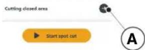
4.7.6. USTAWIENIA (SETTINGS)
(Supply of Machinery (Safety) Regulations 2008, S.I. 2008 No. 1597, Annex II, part A)
- The Company: ST.S.p.A.-Via del Lavoro, 6-31033 Castelfranco Veneto (TV)-Italy 2.Herby declares under its own responsibility that the machine: Robotic lawnmower

- Conforms to UK Regulations:
S.I. 2008/1597 - Supply of Machinery (Safety) Regulations 2008
e) Approved Body: Not Applicable f) Type-examination: Not Applicable
S.I.2017/1206- The Radio Equipment Regulation 2016
S.I.2016/1091-Electromagnetic Compatibility Regulation
( xt^2 - 5x^2) t + xy^2 = ( x) f^
S.I. 2012/3032 - The Restrictions of the Use of Certain Hazardous Substances in Electrical and Electronic Equipment Regulations 2012
m - 1 0 ;
EN60335-1:2012/AC:2014/A11:2014/A13:2017/A1:2019/ BS EN 55014-1:2017/A11:2020
2018/A14:2019 BS EN 55014-2:2015
ENIEC63000:2018 BS EN 61000-3-2:2019
EN308447V12.0 BS EN 61000-3-3:2013/A1:2019
EN50636-107:2015/A1/A2 BS EN 300 328 V2.2.2
EN 62479:2010 BS EN 301 489-17 V3.2.4
Range of cut: 18 cm
18 cm
ST.S.p.A.
Via del Lavoro, 6
31033 Castelfranco Veneto (TV)-Italia
CEO Stiga Group

1775142900
| F1 (Pseudomonas aeruginosa) |
| Declarant: De Cerebraria |
| Directive Vertriebs 2008/42DE, Ameio e. gaitelo
Erlaizão |
| 3. Diederich am das praesige neoplasiaque que a
immeiorta, Rodoferrostradiaca
e Type I Modo de Doze
Lipid em Desenvolvimento |
| 3.1: Olenal de doceologia
de Kolo
Mensur de Salud
Ceramica de Companhao
de Minas Gerais
Ceramica de Conferencia
de Camero CD de Tpo
Remarca de latorce
Companhao de percepcao da
distraccao
Ceramica CD de Tpo
Remarca de latorce
Remarca de doceologia
de Camero CD de Tpo
Remarca de latorce
Remarca de doceologia
Remarca de doceologia
Remarca de doceologia
Remarca de doceologia
Remarca de doceologia
Remarca de doceologia
Remarca de doceologia
Remarca de doceologia
Remarca de doceologia
Remarca de doceologia
Remarca de doceologia
Remarca de doceologia
Remarca de doceologia
RemarCA de doceologia
Remarca de doceologia
Remarca de doceologia
Remarca de doceologia
Remarca de doceologia
Remarca de doceologia
Remarca de doceologia
Remarca de doceologia
Remarca de doceologia
Remarca de doceologia
Remarca de doceologia
Remarca de doceologia
Remarca de doceologna
Remarca de doceologia
Remarca de doceologia
Remarca de doceologia
Remarca de doceologia
Remarca de doceologia
Remarca de doceologia
Remarca de doceologia
Remarca de doceologia
Remarca de doceologia
Remarca de doceologia
Remarca de doceologia
Remarca de doceologia
Remarcas de doceologia
Remarca de doceologia
Remarca de doceologia
Remarca de doceologia
Remarca de doceologia
Remarca de doceologia
Remarca de doceologia
Remarca de doceologia
Remarca de doceologia
Remarca de doceologia
Remarca de doceologia
Remarca de doceologia
Remarca de doceologica
Remarca de doceologia
Remarca de doceologia
Remarca de doceologia
Remarca de doceologia
Remarca de doceologia
Remarca de doceologia
Remarca de doceologia
Remarca de doceologia
Remarca de doceologia
Remarca de doceologia
Remarca de doceologia
Remarca de doceologia
Remarcar de doceologia
Remarca de doceologia
Remarca de doceologia
Remarca de doceologia
Remarca de doceologia
Remarca de doceologia
Remarca de doceologia
Remarca de doceologia
Remarca de doceologia
Remarca de doceologia
Remarca de doceologia
Remarca de doceologia
Remarca de doceologiag
Remarca de doceologia
Remarca de doceologia
Remarca de doceologia
Remarca de doceologia
Remarca de doceologia
Remarca de doceologia
Remarca de doceologia
Remarca de doceologia
Remarca de doceologia
Remarca de doceologia
Remarca de doceologia
Remarca de doceologia
Remarra de doceologia
Remarca de doceologia
Remarca de doceologia
Remarca de doceologia
Remarca de doceologia
Remarca de doceologia
Remarca de doceologia
Remarca de doceologia
Remarca de doceologia
Remarca de doceologia
Remarca de doceologia
Remarca de doceologia
Remarca de doceologicag
Remarca de doceologia
Remarca de doceologia
Remarca de doceologia
Remarca de doceologia
Remarca de doceologia
Remarca de doceologia
Remarca de doceologia
Remarca de doceologia
Remarca de doceologia
Remarca de doceologia
Remarca de doceologia
Remarca de doceologia
Remerca de doceologia
Remerca de doceologia
Remerca de doceologia
Remerca de doceologia
Remerca de doceologia
Remerca de doceologia
Remerca de doceologia
Remerca de doceologia
Remerca de doceologia
Remerca de doceologia
Remerca de doceologia
Remerca de doceologia
Remerca de dozceologia
Remerca de doceologia
Remerca de doceologia
Remerca de doceologia
Remerca de doceologia
Remerca de doceologia
Remerca de doceologia
Remerca de doceologia
Remerca de doceologia
Remerca de doceologia
Remerca de doceologia
Remerca de doceologia
Remerca de doceologia
Roper de doceologia
Remerca de doceologia
Remerca de doceologia
Remerca de doceologia
Remerca de doceologia
Remerca de doceologia
Remerca de doceologia
Remerca de doceologia
Remerca de doceologia
Remerca de doceologia
Remerca de doceologia
Remerca de doceologia
Remerca de doceologica
Remerca de doceologia
Remerca de doceologia
Remerca de doceologia
Remerca de doceologia
Remerca de doceologia
Remerca de doceologia
Remerca de doceologia
Remerca de doceologia
Remerca de doceologia
Remerca de doceologia
Remerca de doceologia
Remerca de doceologia
RemerCA de doce
RemerCA de doce
RemerCA de doce
RemerCA de doce
RemerCA de doce
RemerCA de doce
RemerCA de doce
RemerCA de doce
RemerCA de doce
RemerCA de doce
RemerCA de doce
RemerCA de doce
RemerCA de doce
RemerCA de doce
RemerCA de doce
Roper de doceologia
Remerca de doceologia
Remerca de doceologia
Remerca de doceologia
Remerca de doceologia
Remerca de doceologia
Remerca de doceologia
Remerca de doceologia
Remerca de doceologia
Remerca de doceologia
Remerca de doceologia
Remerca de doceologia
Remercade doceologia
Remerca de doceologia
Remerca de doceologia
Remerca de doceologia
Remerca de doceologia
Remerca de doceologia
Remerca de doceologia
Remerca de doceologia
Remerca de doceologia
Remerca de doceologia
Remerca de doceologia
Remerca de doceologia
Remerca de doceologia | EC-Interferonα-α-α-α-α-α-α-α-α-α-α-α-α-α-α-α-α-α-α-α-α-α-α-α-α-α-α-α-α-α-α-α-α-α-α-α-α-α-α-α-α-α-α-α-α-α-α-α-α-α-α-
EC-Interferonα-α-α-α-α-α-α-α-α-α-α-α-α-α-α-α-α-α-α-α-α-α-α-α-α-α-α-α-α-α-α-α-α-α-α-α-α-α-α-α-α-α-α-α-α-α-α-à-α-α-α-α-α-α-α-α-α-α-α-α-α-α-α-α-α-α-α-α-α-α-α-α-α-α-α-α-α-α-α-α-α-α-α-α-α-α-α-α-α-α-α-α-α-α-α-α-α-à-α-α
EC-Interferonα-α-α-α-α-α-α-α-α-α-α-α-α-α-α-α-α-α-α-α-α-α-α-α-α-α-α-α-α-α-α-α-α-α-α-α-α-α-α-α-α-α-α-α-α-α-α-β-α-α
EC-Interferonα-α-α-α-α-α-α-α-α-α-α-α-α-α-α-α-α-α-α-α-α-α-α-α-α-α-α-α-α-α-α-α-α-α-α-α-α-α-α-α-α-α-α-α-α
EC-Interferonα-α-α-α-α-α-α-α-α-α-α-α-α-α-α-α-α-α-α-α-α-α-α-α-α-α-α-α-α-α-α-α-α-α-α-α-α-α-α-α-α-α-α-α-α-
EC-Interferonα-α-δ-δ-δ-δ-δ-δ-δ-δ-δ-δ-δ-δ-δ-δ-δ-δ-δ-δ-δ-δ-δ-δ-δ-δ-δ-δ-δ-δ-δ-δ-δ-δ-δ-δ-δ-δ-δ-δ-δ-δ-δ-δ-δ-δ-δ-δ-δ-δ-δ-δ- δ-δ-δ-δ-δ-δ-δ-δ-δ-δ-δ-δ-δ-δ-δ-δ-δ-δ-δ-δ-δ-δ-δ-δ-δ-δ-δ-δ-δ-δ-δ-δ-δ-δ-δ-δ-δ-δ-δ-δ-δ-δ-δ-δ-δ-δ-δ-δ-δ-δ- |
| EC-Interferonα-α-α-α-α-α-α-α-α-α-α-α-α-α-α-α-α-α-α-α-α-α-α-α-α-α-α-α-α-α-α-α-α-α-α-α-α-α-α-α-α-α-α-α-α-α-α
EC-Interferonα-α-δ-δ-δ-δ-δ-δ-δ-δ-δ-δ-δ-δ-δ-δ-δ-δ-δ-δ-δ-δ-δ-δ-δ-δ-δ-δ-δ-δ-δ-δ-δ-δ-δ-δ-δ-δ-δ-δ-δ-δ-δ-δ-δ-δ-δ- δ-δ-δ-δ- | |
| EC-Interferonα-α-α-α-α-α-α-α-α-α-α-α-α-α-α-α-α-α-α-α-α-α-α-α-α-α-α-α-α-α-α-α-α-α-α-α-α-α-α-α-α-α- α
EC-Interferonα-α-δ-δ-δ-δ-δ-δ-δ-δ-δ-δ-δ-δ-δ-δ-δ-δ-δ-δ-δ-δ-δ-δ-δ-δ-δ-δ-δ-δ-δ-δ-δ-δ-δ-δ-δ-δ-δ-δ-δ-δ-δ-δ-δ-δ-δ - | |
| EC-Interferonα-α-α-α-α-α-α-α-α-α-α-α-α-α-α-α-α-α-α-α-α-α-α-α-α-α-α-α-α-α-α-α-α-α-α-α-α-α-α-α-α-α-α-α-α-α
EC-Interferonα-δ-δ-δ-δ-δ-δ-δ-δ-δ-δ-δ-δ-δ-δ-δ-δ-δ-δ-δ-δ-δ-δ-δ-δ-δ-δ-δ-δ-δ-δ-δ-δ-δ-δ-δ-δ-δ-δ-δ-δ-δ-δ-δ-δ-δ-δ-δ-δ-δ
EC-Interferonα-α-δ-δ-δ-δ-δ-δ-δ-δ-δ-δ-δ-δ-δ-δ-δ-δ-δ-δ-δ-δ-δ-δ-δ-δ-δ-δ-δ-δ-δ-δ-δ-δ-δ-δ-δ-δ-δ-δ-δ-δ-δ-δ-δ-δ-δ
EC-Interferonα-α
EC-Interferonα
EC-Interferonα
EC-Interferonα
EC-Interferonα
EC-Interferonα
EC-Interferonα
EC-Interferonα
EC-Interferonα
EC-Interferonα
EC-Interferonα
EC-Interferonα
EC-Interferonα
EC-Interferonα
EC-Interferonα
EC-Interferonα | |
| RU/undiciplinienkurskundeprachung |
| Durchschnittliche Schuldsätze |
| Die konsumentäre und leistungs- und immaterielle Verlustvorträge (2006-2012) je gewährt auf das Plan der Gesamtgesellschaft | DEutschland: COBURNSTAMME AG, Münster, Deutschland: 334242C, Rumänien, Europa: A. |
| 2. Prüfungssystem für früherer Zeitwert | 1. Schutz: |
| 3. Anzahlung der gesetzlichen Gewinnen und Verluste | 2. Partikelkonsumenten aus dem Geschäftsjahr 2013 bis 2015, bestand 1, die zu-
determineden Zeitwert von 2013 bis 2015 erfasst sind |
| 4. Zahlungsmittel in der kurzfristigen Zeitwerte | 3. Derivate: Aktiva, Options, Options, Options, Options, Options, Options, Options, Options, Options, Options, Options, Options, Options, Options, Options, Options, Options, Options, Options, Options, Options, Options, Options, Options, Options, Options, Options, Options, Options, Options, Options, Options, Options, Options, Options, Options, Options, Options, Options, Options, Options, Options, Options, Options, Options, Options, Options, Options, Options, Options,Options, Options, Options, Options, Options, Options, Options, Options, Options, Options, Options, Options, Options, Options, Options, Options, Options, Options, Options, Options, Options, Options, Options, Options, Options, Options, Options, Options, Options, Options, Options, Options, Options, Options, Options, Options, Options, Options, Options, Options, Options, Options, Options, Options, Options, Options, Options, Options, Options, Options, |
| 5. Gruppengeschäfte | 4. Derivate: Aktiva, Options, Options, Options, Options, Options, Options, Options, Options, Options, Options, Options, Options, Options, Options, Options, Options, Options, Options, Options, Options, Options, Options, Options, Options, Options, Options, Options, Options, Options, Options, Options, Options, Options, Options, Options, Options, Options, Options, Options, Options, Options, Options, Options, Options, Options, Options,Options, Options, Options,Options, Options, Options, Options, Options, Options, Options, Options, Options, Options, Options, Options, Options, Options, Options, Options, Options, Options, Options, Options, Options, Options, Options, Options, Options, Options, Options, Options, Options, Options, Options, Options, Options, Options, Options, Options, Options, Options, Options, Options, Options, Options, Options, Options, Options, Options, Options,Options, Options, Options, |
| 6. Finanzschulden | 5. Derivate: Aktiva, Options, Options, Options, Options, Options, Options, Options, Options, Options, Options, Options, Options, Options, Options, Options, Options, Options, Options, Options, Options, Options, Options, Options, Options, Options, Options, Options, Options, Options, Options, Options, Options, Options, Options, Options, Options, Options, Options, Options, Options, Options, Options, Options, Options, Options, Options, |
| 7. Finanzschulden | 6. Derivate: Aktiva, Options, Options, Options, Options, Options, Options, Options, Options, Options, Options, Options, Options, Options, Options, Options, Options, Options, Options, Options, Options, Options, Options, Options, Options, Options, Options, Options, Options, Options, Options, Options, Options, Options, Options, Options, Options, Options, Options, Options, Options, Options, Options, Options, Options, Options, Options, . |
/TIGA
STIGALTD (UK Importer)
Unit 8, Bluewater Estate Plympton,
Devon, PL7 4JH, England
STIGAS.p.A.
Via del lavoro, 6
31033 Castelfranco Veneto (TV)
Italy
/TIGA stig
Stig 300
Stig 600
Stig 1200
ELHELYEZÉS A RÖGZÍTÓ SZÖGEKKEL

| Stig 300 Stig 600 Stig 1200 |
| Border Cut | ✓ | ✓ | ✓ |
| Run Beside Wire | X | ✓ | ✓ |
| Go-To Cut Points | 135 | | |
| Eco Mode | X | X | ✓ |
| Rain Sensor | X | ✓ | ✓ |
| Closed Area | X | X | ✓ |
A TERMÉK BEÁLLITÁSAINAK TARTALOMJEGYZÉKE
4.7.1. PRELOGIN 31
4.7.2. REGISZTRACIO (SIGN UP) 31
4.7.3. PAROSITAS (PAIRING) 32
4.7.4.ATERMEKABLAKA (DEVICEPAGE) 33
4.7.5.ZART TERULET (CLOSED AREA) 33
4.7.6. BEÁLLITÁSOK (SETTINGS) 33
4.7.7. EGYSZERI FUNYIRAS/UTEMEZETT FUNYIRAS (SPOT CUT/SCHEDULED) 34
4.7.8. FUNYIRASI MUNKAMENETEK (MOWING SESSIONS) 34
4.7.9. GO-TO-CUT POINTS 35
4.7.10.A GYEP SZELENEK NYIRASA (BORDER CUT) 36
4.7.11. ECO MODE 36
4.7.12. ESOERZEKELO (RAIN SENSOR) 36
4.7.13.FELHASNZALOK KEZELESE 37
4.7.14. MARKAKERESKEDOK (DEALER) 37
4.7.15. ÜZENETEK (MESSAGE) 38
4.7.16.PROFIL (PROFILE) 38
4.7.1.PRELOGIN

Status On
Mowing Mode I'm mowing
All sectors


4.7.5.ZART TERULET (CLOSED AREA)
MEGJEGYZES: Ellenorizze a funkció megletét a STIGA.GO applícáioban.
m = 311

51

m

附件1:

特此公告。

rate

图

总经


m = 311 ;

1

m = 311


12 1

det

15

08


010

det

in

特此公告。

图1

nighhe


(二)


m = 311


m = 311 ;


m = 311

1

1

m = 311

m = 311

1

m = 311

2 : x^ ( x) = 10的1.2

1

m = 311

m = 311

1


m = 311


13/14

13/14

1

UNT

m = 311

m = 311 ;


13/14

m = 311

m = 311 ;


图

3.1


m = 311

7


2 : x^ ( x) = y^ ( x) : 2 : x^ ( x) = y^ ( x) : y = 10( x)


m = 311

.

D.

13/14

m = 311 ;


31 + u + 4q = 1 + u + uq dH

13/14

m = 311

12 =


5. MUKÖDÉS
MEGJEGYZES: A robotfyniroCsakafedel (B)lezarasa utan indithato el.
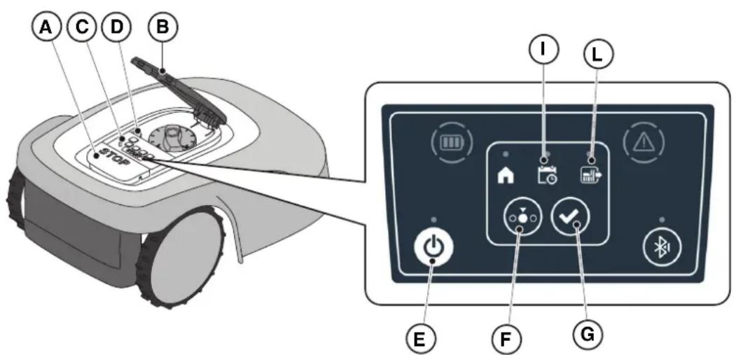
A "BLUETOOTH" gomb (M):
S.I. 2008/1597 - Supply of Machinery (Safety) Regulations 2008
e) Approved Body: Not Applicable
f) Type-examination: Not Applicable
S.J.2017/1206- The Radio Equipment Regulation 2016
S.1.2016/1091-Electromagnetic Compatibility Regulations 2016
S.I. 2012/3032 - The Restrictions of the Use of Certain Hazardous Substances in Electrical and Electronic Equipment
Regulations 2012
STIGALTD (UK Importer)
Unit 8, Bluewater Estate Plympton,
Devon, PL7 4JH, England
STIGAS.p.A.
Via del lavoro, 6
31033 Castelfranco Veneto (TV)
Italy
/TIGA stig
Stig 300
Stig 600
Stig 1200
ET Kasutusjuhend
EESTI KEEL - ALGUPÄRASE KASUTUSJUHENDI TÖLGE
SISUKORD
1. MUDELID JA TEHNILISED ANDMED 1
1.1. MUDELID 1
1.2. TEHNILISED ANDMED - STIGA STIG 2
2. OHUTUS 3
2.1. OHUTUSALANE TEAVE 3
2.2. OHUTUSEESKIRJAD 5
2.2.1. TURVALISED TOÖVÖTTED 5
2.2.2. TÖÖPÖHIMÖTE 5
2.3. ROBOTNIIDUKI SEISKAMINE JA VÄLJALÜLITAMINE OHUTUSTINGIMUSTES 7
3. SISSEJUHATUS 8
3.1. ULDINE SISSEJUHATUS 8
3.1.1.JUHENDI EESMARK. 8
3.1.2. JUHISED LUGEMISEKS NUTITELEFONIST 8
3.2. TOOTEULEVAADE 9
3.2.1. ULDINE KIRJELDUS 9
3.2.2. POHIKOMPONENDID 10
3.3.PAKENDISTVALJAVOTMINE 11
3.4.SUMBOLID JA ANDMEPLAADID 12
3.5.JUHENDI LUGEMISE ULDISED JUHISED 13
4. PAIGALDAMINE 14
4.1. ULDTEAVE PAIGALDAMISE KOHTA 14
4.2. PAIGALDAMISEKS VAJALIKUD KOMPONENDID 14
4.3. PAIGALDAMISNOUETE KONTROLLIMINE 15
4.3.1. AIA KONTROLLIMINE: 15
4.3.2. KONTROLLID LAADIMISJAAMA JA TOITESEADME PAIGALDAMISEKS: 15
4.3.3. PÖHIKONTROLLID PIIREKAABLI PAIGALDAMISEKS: 17
4.4. PIIRDEKAABLI PAIGALDAMISE KRITEERIUMID 19
4.4.1. PIIRDEKAABLI KOHALE ASETAMINE 19
4.4.2. TAKISTUSTE PIIRITLEMINE: 21
4.4.3. ULEMINEKUD AIA ERI ALADE VAHEL 23
4.5. KOMPONENTIDE PAIGALDAMINE 23
4.5.1. PIIRDEKAABLI PAIGALDAMINE 24
4.5.2. PIIRDEKAABLI JATKAMINE 25
4.5.3. LAADIMISJAAMA PAIGALDAMINE 26
4.5.4. RESISTORI PAIGALDAMINE VAIKESTE PERIMEETRITE JAOKS 28
4.6. ROBOTNIIDUKI LAADIMINE PÄRAST PAIGALDAMIST 29
4.7. TOOTE SEADISTUSED 30
5. TÖÖPÖHIMÖTE
5.1. TURVASEADISTE KONTROLLIMINE ROBOTNIIDUKI KÄIVITAMISEKS 39
5.2. ROBOTNIIDUKI MANUALNE TÖTAMINE 40
5.3. ROBOTNIIDUKI JUHTSEADMETE KIRJELDUS 41
5.3.1. OHUTU SEISKAMINE - STOPP NUPP 41
5.3.2. KUSTUTAMINE OHUTUSTINGIMUSTES - TURVAVOTI 42
5.3.3. SISSE- JA VÄLJALÜLITAMINE - NUPP ON/OFF 42
5.3.4. KAVANDATUD PROGRAMMI / UKSIKU TOOTSKI VALIMINE - KAVANDATUD PROGRAMMI NUPP .... 43
5.3.5. BLUETOOTHI OLEKU KUVAMINE JA LAHTI UHENDAMINE - NUPP BLUETOOTH 45
5.3.6. ALARMIOLEKUTE KUVAMINE - ALARMIIKOON 45
5.3.7. AKU LAETUSE OLEKU KUVAMINE - AKU IKOON 46
5.3.8. ROBOTNIIDUKI KAIVITAMINE - NUPP START 46
5.4. LAADIMISJAAMA TÖOTAMINE 47
5.5.AKU LAADIMINE 47
5.6. NIITMISKÖRGUSE REGULEERIMINE 48
6. HOOLDUS 49
6.1. KORRALINE HOOLDUS 49
6.2. TOOTE PUHASTAMINE 50
6.3. LOIKETERADE VAHETAMINE 52
6.4. AKU TALVEKS HOOLDAMINE JA HOIULE PANEMINE3
6.5.AKU VAHETAMINE 53
7.PROBLEEMIDE LAHENDAMINE 54
7.1. PEAMISED API TEATED 55
8. TRANSPORT, LADUSTAMINE JA KÖRVALDAMINE 57
8.1. TRANSPORT 57
8.2. HOIDMINE 57
8.3. KORVALDAMINE 57
9. LISASEADMED 58
10.GARANTII 59
10.1.GARANTII KATE 59
11.EU VASTAVUSDEKLARATSIOON 60
1. MUDELID JA TEHNILISED ANDMED
1.1.MUDELID
4.7. TOOTE SEADISTUSED

Status: On
Mowing Mode: I'm mowing
All ≤ 10


4.7.5. SULETUD ALA (CLOSED AREA)
MÄRKUS: Kontrollige, kas see funktsoon on saadaval äpis STIGA.GO.
4.7.6. SEADISTUSED ( SETTINGS)