
LZH200GBA2 - Air-conditioner LG - Free user manual and instructions
Find the device manual for free LZH200GBA2 LG in PDF.
User questions about LZH200GBA2 LG
0 question about this device. Answer the ones you know or ask your own.
Ask a new question about this device
Download the instructions for your Air-conditioner in PDF format for free! Find your manual LZH200GBA2 - LG and take your electronic device back in hand. On this page are published all the documents necessary for the use of your device. LZH200GBA2 by LG.
USER MANUAL LZH200GBA2 LG
Please read this manual carefully before operating your set and retain it for future reference.
TYPE : VENTILATOR
Ventilator Owner's Manual
TABLE OF CONTENTS
Safety Precautions....3
Prior to Operation 6
Introduction ......7
Operating Instructions (Accessory) ....10
Electrical Safety 14
Characteristics ......15
Maintenance and Service .....17
Check Item prior to notify a failure 22
FOR YOUR RECORDS
Write the model and serial numbers here:
Model #
Serial #
You can find them on a label on the side of each unit.
Dealer's Name
Date Purchased
■Staple your receipt to this page in the event you need it to prove date of purchase or for warranty issues.

READ THIS MANUAL
Inside you will find many helpful hints on how to use and maintain your ventilator properly. Just a little preventive care on your part can save you a great deal of time and money over the life of your Ventilator.
You'll find many answers to common problems in the chart of check item prior to notify a failure. If you review our chart of
Check item prior to notify a failure, you may not need to call for service at all.

PRECAUTION
- Contact the authorized service technician for repair or maintenance of this unit.
- Contact the installer for installation of this unit.
- The ventilator is not intended for use by young children or invalids without supervision.
- Young children should be supervised to ensure that they do not play with the ventilator.
- When the power cord is to be replaced, replacement work shall be performed by authorized personnel only using only genuine replacement parts.
- Installation work must be performed in accordance with the National Electric Code by qualified and authorized personnel only.

text_image
authorized personnel only.Safety Precautions
To prevent injury to the user or other people and property damage, the following instructions must be followed.
■Incorrect operation due to ignoring instruction will cause harm or damage. The seriousness is classified by the following indications.

WARNING
This symbol indicates the possibility of death or serious injury.

CAUTION
This symbol indicates the possibility of injury or damage.
■Meanings of symbols used in this manual are as shown below.


Be sure not to do.
Be sure to follow the instruction.

WARNING
■Installation
Do not use a defective or underrated circuit breaker. Use this appliance on a dedicated circuit.
- There is risk of fire or electric shock.
For electrical work, contact the dealer, seller, a qualified electrician, or an Authorized Service Center.
- Do not disassemble or repair the product. There is risk of fire or electric shock.
Always ground the product.
- There is risk of fire or electric shock.
Install the panel and the cover of control box securely.
Always install a dedicated circuit and breaker.
Use the correctly rated breaker or fuse.
- There is risk of fire or electric shock.
- Improper wiring or installation may cause fire or electric shock
- There is risk of fire or electric shock.
Do not modify or extend the power cable.
Do not install, remove, or re-install the unit by yourself (customer).
Be cautious when unpacking and installing the product.
- There is risk of fire or electric shock.
• There is risk of fire, electric shock, explosion, or injury.
- Sharp edges could cause injury. Be especially careful of the case edges and the fins on the condenser and evaporator.
For installation, always contact the dealer or an Authorized Service Center.
Do not install the product on a defective installation stand.
Do not let the ventilator run for a long time when the humidity is very high and a door or a window is left open.
• There is risk of fire, electric shock, explosion, or injury.
- It may cause injury, accident, or damage to the product.
- Moisture may condense and wet or damage furniture.
For re-installation of the installed product, always contact the dealer or an Authorized Service Center.
- There is risk of fire, electric shock, explosion or injury.
Do not open the maintenance cover of the main body during operation.
- Otherwise, it may cause electrical shock.
Use the outdoor air suction hole with the net installed to ensure that birds could not come in.
- Remove estrange things like the bird's nest. Otherwise, it may cause scarcity of indoor oxygen.
Install the air intake where polluted air can not be directly sucked in.
- It may cause various accidents, including suffocation, due to the suction of harmful gasses(CO, etc.)
Install the product a place that can support its weight.
- Otherwise, it may cause accident due to falling of the product.
Operation
Take care to ensure that power cable could not be pulled out or damaged during operation.
- There is risk of fire or electric shock.
Do not touch(operate) the product with wet hands.
- There is risk of fire or electrical shock.
Do not store or use flammable gas or combustibles near the product.
- There is risk of fire or failure of product.
Stop operation and close the window in storm or hurricane. If possible, remove the product from the window before the hurricane arrives.
- There is risk of property damage, failure of product, or electric shock.
Do not place anything on the power cable.
- There is risk of fire or electric shock.
Do not place a heater or other appliances near the power cable.
- There is risk of fire and electric shock.
When flammable gas leaks, turn off the gas and open a window for ventilation before turn the product on.
- Do not use the telephone or turn switches on or off. There is risk of explosion or fire
When the product is soaked (flooded or submerged), contact an Authorized Service Center.
- There is risk of fire or electric shock.
Do not plug or unplug the power supply plug during operation.
- There is risk of fire or electric shock.
Do not allow water to run into electric parts.
- It may cause There is risk of fire, failure of the product, or electric shock.
If strange sounds, or small or smoke comes from product. Turn the breaker off
- There is risk of electric shock or fire.
Be cautious that water could not enter the product.
- There is risk of fire, electric shock, or product damage.
Turn the breaker off when cleaning or maintaining the product.
- There is risk of electric shock.
When the product is not be used for a long time, disconnect the power supply plug or turn off the breaker.
- There is risk of product damage or failure, or unintended operation.
Avoid fire equipment
- There is risk of fire.
Don't touch a dedicated circuit or breaker with wet hands.
- There is risk of electric shock.
Use a firm stool or ladder when cleaning or maintaining the roduct.
- Be careful and avoid personal injury.

CAUTION
Installation
Use two or more people to lift and transport the product.
- Avoid personal injury.
Do not install the product where it will be exposed to sea wind (salt spray) directly.
- It may cause corrosion on the product. Corrosion, particularly on the condenser and evaporator fins, could cause product malfunction or inefficient operation.
Operation
Do not expose the skin directly to cool air for long periods of time. (Don't sit in the draft.)
• This could harm to your health.
Do not use the product for special purposes, such as preserving foods, works of art, etc. It is a consumer ventilator, not a precision refrigeration system.
- There is risk of damage or loss of property.
Use a soft cloth to clean. Do not use harsh detergents, solvents, etc.
- There is risk of fire, electric shock, or damage to the plastic parts of the product.
Do not step on or put anything on the product. (outdoor units)
- There is risk of personal injury and failure of product.
Use a firm stool or ladder when cleaning or maintaining the product.
- Be careful and avoid personal injury.
Prior to Operation
Preparing for operation
- Contact an installation specialist for installation.
- Plug in the power plug properly.
- Use a dedicated circuit.
- Do not use an extension cord.
- Do not start/stop operation by plugging/unplugging the power cord.
- If the cord/plug is damaged, replace it with only an authorized replacement part.
Usage
- Being exposed to direct airflow for an extended period of time could be hazardous to your health. Do not expose occupants, pets, or plants to direct airflow for extended periods of time.
- Due to the possibility of oxygen deficiency, ventilate the room when used together with stoves or other heating devices.
- Do not use this ventilator for non-specified special purposes (e.g. preserving precision devices, food, pets, plants, and art objects). Such usage could damage the items.
Cleaning and maintenance
- Do not touch the metal parts of the unit when removing the filter. Injuries can occur when handling sharp metal edges.
- Do not use water to clean inside the ventilator. Exposure to water can destroy the insulation, leading to possible electric shock.
- When cleaning the unit, first make sure that the power and breaker are turned off. The fan rotates at a very high speed during operation. There is a possibility of injury if the unit's power is accidentally triggered on while cleaning inner parts of the unit.
Service
For repair and maintenance, contact your authorized service dealer.
Introduction
Symbols used in this Manual

This symbol alerts you to the risk of electric shock.

This symbol alerts you to hazards that could cause harm to the ventilator.
NOTICE
This symbol indicates special notes.
Features

WARNING: This appliance should be installed in accordance with national wiring regulations. This guide acts as a guide to help to explain product features.
Models: LZ-H015GBA2
text_image
Technical diagram of a mechanical device with numbered components for identification- Blower for Supply Air
A blower for sucking outside air.
-
Control Box
-
Blower for Exhaust Air
A blower for draining polluted air outside.
-
Maintenance cover
-
Total Heat Exchanger
Exchanges temperature and moisture between air supply air and exhaust air.
- Air Filter
Prevents clogging of the Total heat exchanger due to dust.
*The figure of Total Heat Exchanger can be different by the product model.
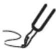
Models: LZ-H025GBA2 / LZ-H035GBA2
text_image
Technical diagram of a mechanical ventilation system with numbered components- Blower for Supply Air
A blower for sucking outside air.
-
Control Box
-
Blower for Exhaust Air
A blower for draining polluted air outside.
-
Maintenance cover
-
Total Heat Exchanger
Exchanges temperature and moisture between air supply air and exhaust air.
- Air Filter
Prevents clogging of the Total heat exchanger due to dust.
*The figure of Total heat Exchanger can be different by the Product Model.
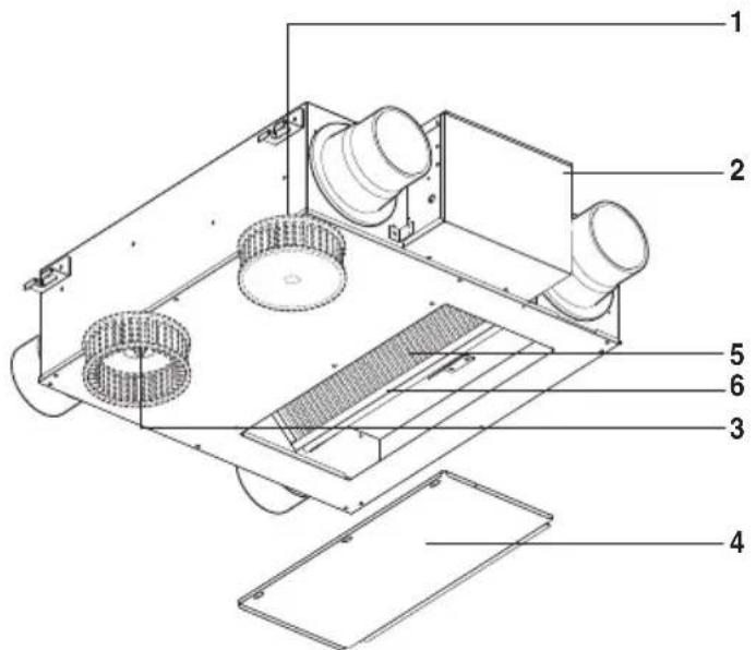
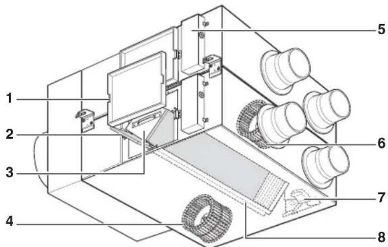
Models: LZ-H050GBA2
text_image
Technical diagram of a vehicle chassis with numbered components for identification-
Maintenance Cover
-
Air Filter
It prevents dust from clogging in Total Heat Exchanger.
- Total Heat Exchanger
It changes temperature and humidity between Supplying Air and exhausted air.
- Blower for Exhaust Air
It is a fan for discharging the contaminated air to outdoor.
-
Control box
-
Blower for Supply Air
It is a fan for inhaling exterior air into an indoor space.
- Damper plate(board)
It converts exchanging mode between total heat ventilation and general ventilation.
- Total Heat Exchanger holder
It is used in guiding for the installation of Total Heat Exchanger.
*The figure of Total heat Exchanger can be different by the Product Model.
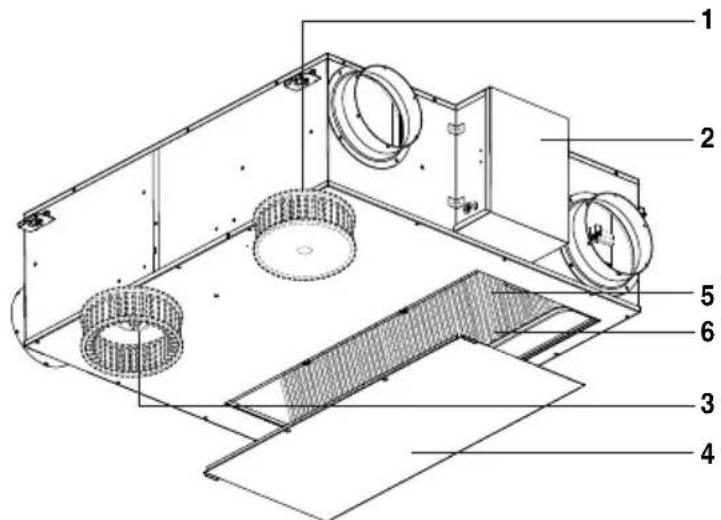
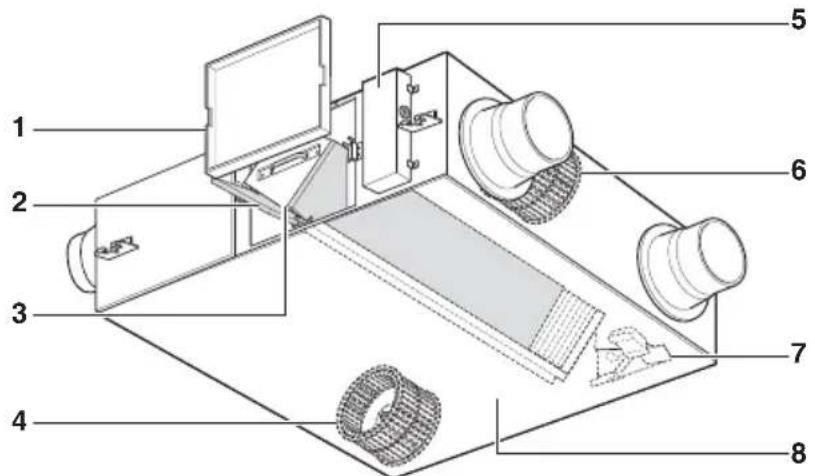
Models: LZ-H080GBA2 / LZ-H100GBA2
text_image
Technical diagram of a vehicle chassis with numbered components for identification- Maintenance Cover
- Air Filter
It prevents dust from clogging in Total Heat Exchanger.
- Total Heat Exchanger
It changes temperature and humidity between Supplying Air and exhausted air.
- Blower for Exhaust Air
It is a fan for discharging the contaminated air to outdoor.
- Control box
- Blower for Supply Air
It is a fan for inhaling exterior air into an indoor space.
- Damper plate(board)
It converts exchanging mode between total heat ventilation and general ventilation.
- Total Heat Exchanger holder
It is used in guiding for the installation of Total Heat Exchanger.
*The form of Total Heat Exchanger varies according to models.
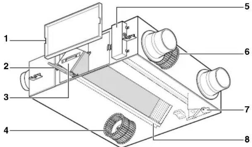
Models: LZ-H150GBA2 / LZ-H200GBA2
text_image
Technical diagram of a mechanical device with numbered components for identification- Maintenance Cover
- Air Filter
It prevents dust from clogging in Total Heat Exchanger.
- Total Heat Exchanger
It changes temperature and humidity between Supplying Air and exhausted air.
- Blower for Exhaust Air
It is a fan for discharging the contaminated air to outdoor.
- Control box
- Blower for Supply Air
It is a fan for inhaling exterior air into an indoor space.
- Damper plate(board)
It converts exchanging mode between total heat ventilation and general ventilation.
- Total Heat Exchanger holder
It is used in guiding for the installation of Total Heat Exchanger.
*The form of Total Heat Exchanger varies according to models.
Operating Instructions (Accessory)
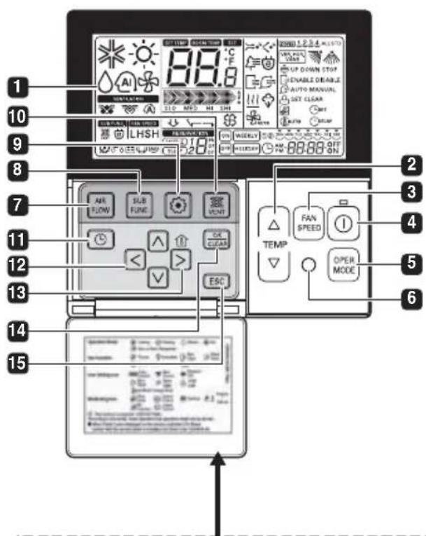
LCD Remote Controller (PQRCVSL0 / PQRCVSL0QW)
text_image
1 2 3 4 5 6 7 8 9 10 11 12 13 14 15 AIR FLOW SUB FLOW VOLT OK CLEAR ESC TEMP FAN SPEED OPER MODEPlease attach the inform label inside of the door. Please choose proper language depend on your country.
1 OPERATION INDICATION SCREEN
2 SET TEMPERATURE BUTTON
3 FAN SPEED BUTTON
4 ON/OFF BUTTON
5 OPERATION MODE SELECTION BUTTON
6 WIRELESS REMOTE CONTROLLER RECEIVER
• Some products don't receive the wireless signals.
7 AIR FLOW BUTTON
8 SUBFUNCTION BUTTON
9 FUNCTION SETTING BUTTON
10 VENTILATION BUTTON
11 RESERVATION
12 UP, DOWN, LEFT, RIGHT BUTTON
- To check the indoor temperature, press ⏻ button.
13 ROOM TEMPERATURE BUTTON
14 SETTING/CANCEL BUTTON
15 EXIT BUTTON
*Some functions may not be operated and displayed depending on the product type.
Method to Operate and Select Air Volume – Interlinked Operation with Ventilation.
It is used when air conditioner is interlinked with ventilation product.
It is a function that cools and refreshes indoor air using the ventilation product at the same time operating the air conditioning function.
text_image
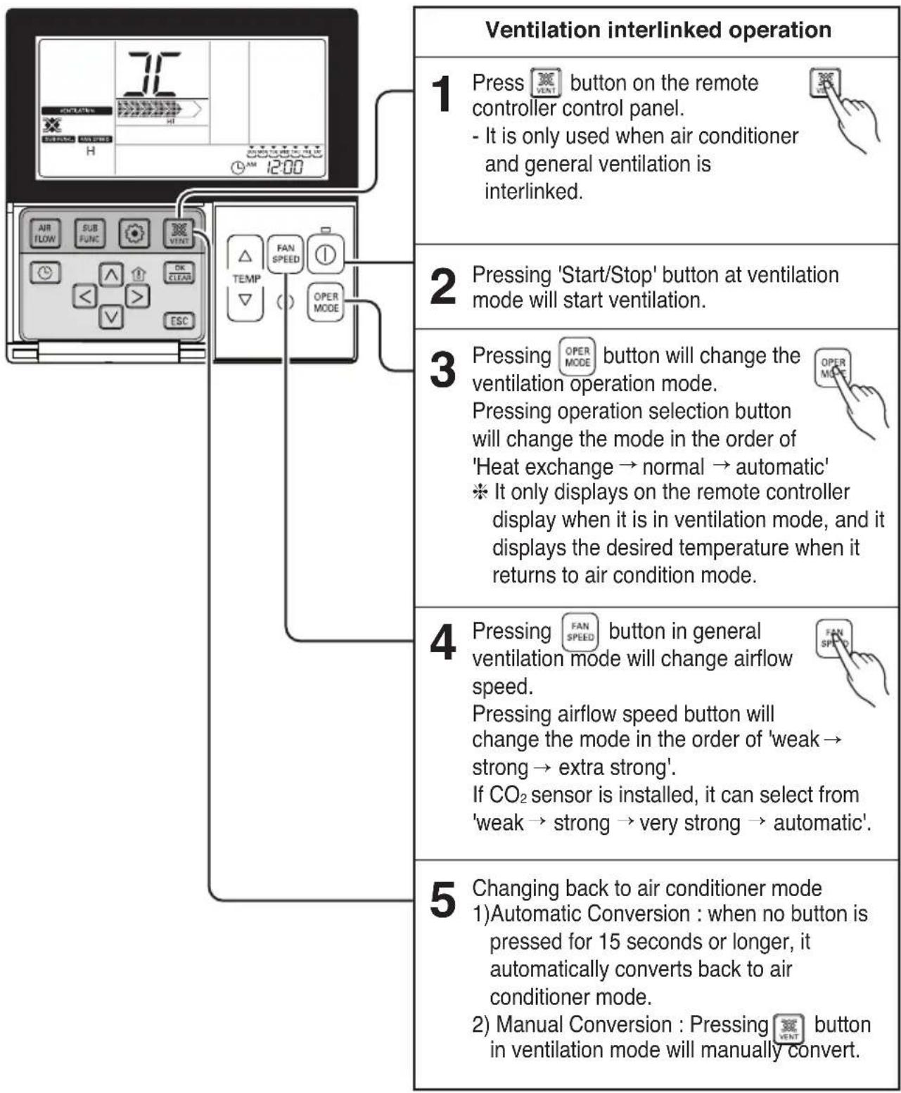
Ventilation interlinked operation 1 Press button on the remote controller control panel. - It is only used when air conditioner and general ventilation is interlinked. 2 Pressing 'Start/Stop' button at ventilation mode will start ventilation. 3 Pressing button will change the ventilation operation mode. Pressing operation selection button will change the mode in the order of 'Heat exchange → normal → automatic' * It only displays on the remote controller display when it is in ventilation mode, and it displays the desired temperature when it returns to air condition mode. 4 Pressing button in general ventilation mode will change airflow speed. Pressing airflow speed button will change the mode in the order of 'weak → strong → extra strong'. If CO₂ sensor is installed, it can select from 'weak → strong → very strong → automatic'. 5 Changing back to air conditioner mode 1) Automatic Conversion : when no button is pressed for 15 seconds or longer, it automatically converts back to air conditioner mode. 2) Manual Conversion : Pressing button in ventilation mode will manually convert.Method to Operate and Select Air Volume – Ventilation Single Operation
It is a function to cool and refresh the indoor air using general ventilation product..
text_image
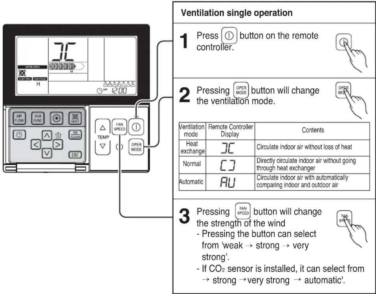
Ventilation single operation 1 Press ① button on the remote controller. 2 Pressing OPER MODE button will change the ventilation mode. Ventilation mode Remote Controller Display Contents Heat exchange □C Circulate indoor air without loss of heat Normal □J Directly circulate indoor air without going through heat exchanger Automatic AU Circulate indoor air with automatically comparing indoor and outdoor air 3 Pressing FAN SPEED button will change the strength of the wind - Pressing the button can select from 'weak → strong → very strong'. - If CO₂ sensor is installed, it can select from → strong → very strong → automatic.Fast/Energy saving ventilation mode
It is a function to operate ventilation function more efficiently through the ventilation additional functions, fast / power saving settings.
text_image
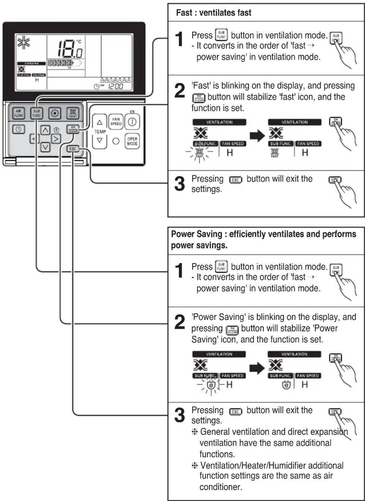
Fast : ventilates fast 1 Press SUB button in ventilation mode. - It converts in the order of 'fast → power saving' in ventilation mode. 2 'Fast' is blinking on the display, and pressing button will stabilize 'fast' icon, and the function is set. 3 Pressing button will exit the settings. Power Saving : efficiently ventilates and performs power savings. 1 Press SUB button in ventilation mode. - It converts in the order of 'fast → power saving' in ventilation mode. 2 'Power Saving' is blinking on the display, and pressing button will stabilize 'Power Saving' icon, and the function is set. 3 Pressing button will exit the settings. * General ventilation and direct expansion ventilation have the same additional functions. * Ventilation/Heater/Humidifier additional function settings are the same as air conditioner.Electrical Safety

WARNING: This appliance must be properly grounded.
To minimize the risk of electric shock, you must alway plug into a grounded outlet.
Preferred method
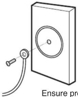
text_image
Ensure proEnsure proper ground exists before use

WARNING: Do not cut or remove the grounding prong from the power wire.

WARNING: Attaching the adapter ground terminal to the wall receptacle cover screw does not ground the appliance unless the cover screw is metal and not insulated, and the wall receptacle is grounded through the house wiring.

WARNING: If you have any doubt whether the ventilator is properly grounded, have the wall receptacle and circuit checked by a qualified electrician.
Characteristics
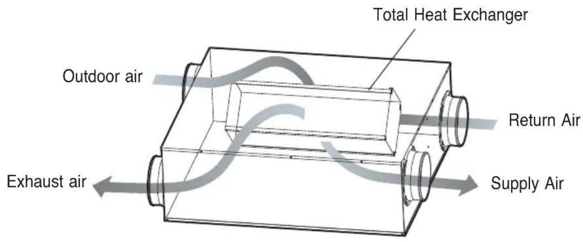
Ventilation via Total Heat Exchanger
Exhausts indoor air via the Total Heat Exchanger outdoor.
- The outdoor air heat exchanged is supplied to indoor. Operate the ventilator in the Ventilation via Total heat exchanger in summer/winter when cool/heat operation is done.
text_image
Total Heat Exchanger Outdoor air Return Air Exhaust air Supply AirVentilation via Total Heat Exchanger
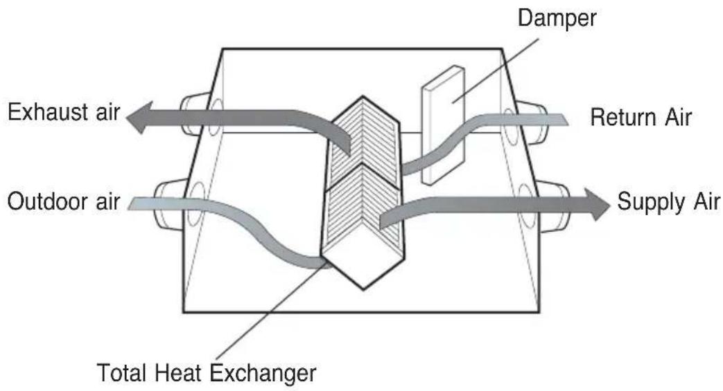
Exhausts indoor air via the Total Heat Exchanger outdoor.
- The outdoor air heat exchanged is supplied to indoor. Operate the ventilator in the Ventilation via Total heat exchanger in summer/winter when cool/heat operation is done.
text_image
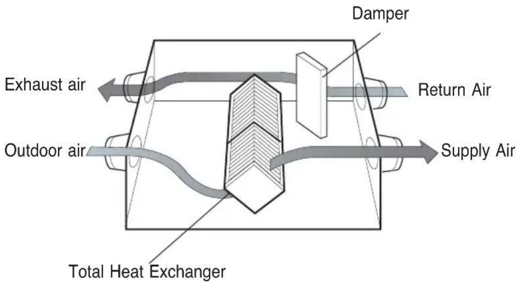
Damper Return Air Exhaust air Outdoor air Supply Air Total Heat ExchangerNormal Ventilation
Exhausts the polluted indoor-air directly without via the Total Heat Exchanger.
- Operate the ventilator in the Normal Ventilation in spring/autumn when the Total heat exchanger is not required.
text_image
Damper Return Air Exhaust air Outdoor air Supply Air Total Heat Exchanger
CAUTION: In case of high outdoor pollution degree like yellow sand please pause the ventilator.
Maintenance and Service
Handling and Cleaning
To prevent function of the ventilator deteriorating, clean dust adhered to the air filter and total heat exchanger regularly.
Cleaning Cycle
- Air filter: More than once every 6 months.
- Total heat exchanger: More than once every 2 years (Cleaning cycle may increase according to pollution degree.)
Method to take each part out
Model: LZ-H015GBA2 / LZ-H025GBA2 / LZ-H035GBA2
1. Remove the maintenance cover.
Put the hands inside of the ceiling from the maintenance cover, and pull the maintenance cover up. (Looser the hinge and detach the maintenance cover.)
2. Take the air filter out.
Take the air filter with each contained to the left/right downside of the Total heat exchanger. *If it adheres to the ceiling in reverse, it is equal to the left/right topside of the Total heat exchanger.

CAUTION: Take care to ensure that you could not damage when taking the air filter out since there is a sharp part on it.
text_image
g- Maintenance cover3. Take the Total heat exchanger out.
Catch the handle and then take the Total heat exchanger out from the main body. (2 units)

WARNING: Turn the breaker off when cleaning the product.

CAUTION: Gloves should be worn when doing the maintenance work.
text_image
Total Heat ExchangerModel: LZ-H050GBA2 / LZ-H080GBA2 / LZ-H100GBA2
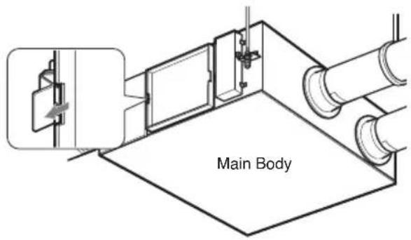
1. Remove the maintenance cover.
Put the hands inside of the ceiling from the maintenance cover, and pull the maintenance cover up. (Looser the hinge and detach the maintenance cover.)
text_image
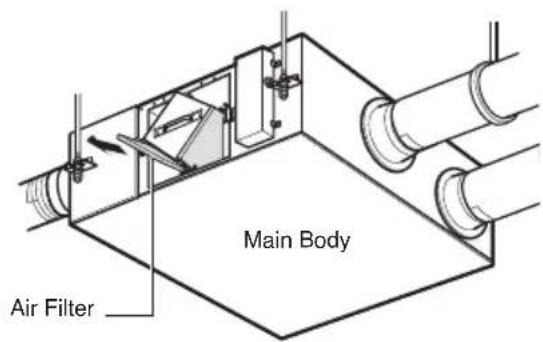
Main Body2. Take the air filter out.
Take the air filter with each contained to the left/right downside of the Total heat exchanger.
*If it adheres to the ceiling in reverse, it is equal to the left/right topside of the Total heat exchanger.

CAUTION: Take care to ensure that you could not damage when taking the air filter out since there is a sharp part on it.
text_image
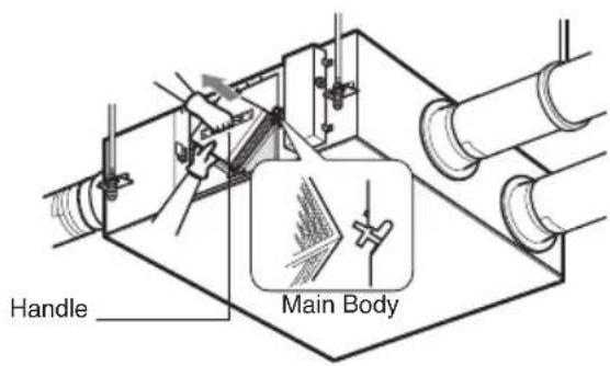
Main Body Air Filter3. Take the Total heat exchanger out.
Catch the handle and then take the Total heat exchanger out from the main body. (2 units)

WARNING: Turn the breaker off when cleaning the product.

CAUTION: Gloves should be worn when doing the maintenance work.
text_image
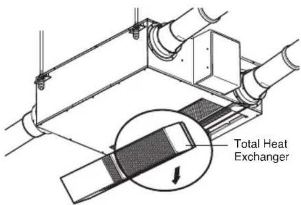
Handle Main BodyModel: LZ-H150GBA2 / LZ-H200GBA2
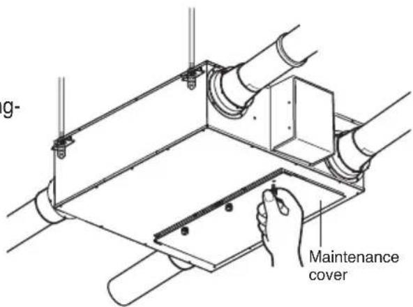
1. Remove the maintenance cover.
Put the hands inside of the ceiling from the maintenance cover, and pull the maintenance cover up. (Looser the hinge and detach the maintenance cover.)
2. Take the air filter out.
Take the air filter with each contained to the left/right downside of the Total heat exchanger. *If it adheres to the ceiling in reverse, it is equal to the left/right topside of the Total heat exchanger.

CAUTION: Take care to ensure that you could not damage when taking the air filter out since there is a sharp part on it.
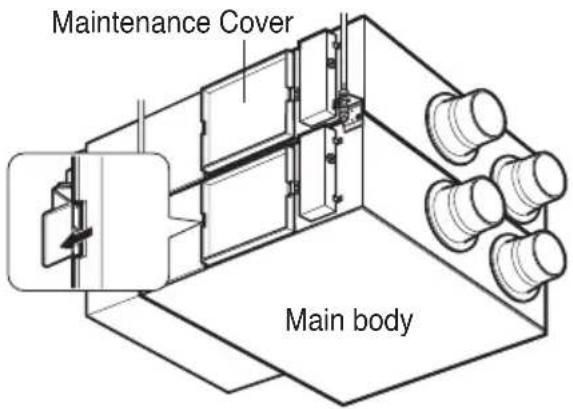
text_image
Maintenance Cover Main body3. Take the Total heat exchanger out.
Catch the handle and then take the Total heat exchanger out from the main body. (2 units)

WARNING: Turn the breaker off when cleaning the product.

CAUTION: Gloves should be worn when doing the maintenance work.
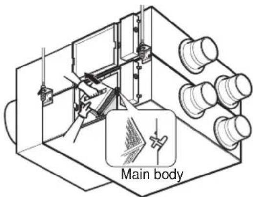
text_image
Main bodyMethod to Clean and Replace Each Part
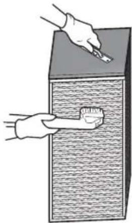
1. Cleaning of Air Filter
Clean once every 6 months.
- Clean dirt from the air filter using a vacuum cleaner or washing with water. (if dirt is conspicuous, wash with a neutral detergent in lukewarm water)
• After washing with water, dry well in the shade. (Do not expose the air filter to direct sunlight or heat from a fire when drying it)
- If the air filter is damaged, purchase it from the service center or professional agent.
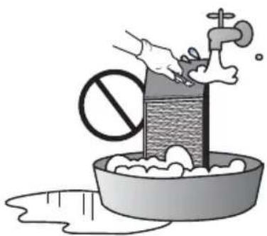
2. Cleaning of Total Heat Exchanger
Suck dusts adhered to the surface of the Total heat exchanger with a cleaner.
- Use the cleaner that attached to brush at its nozzle, and use a soft brush.
- Do not use a hard nozzle on the cleaner. (Otherwise, surface of the Total heat exchanger may be damaged.)
- Never wash the Total heat exchanger with water.
- Replacement expenses are for a consideration after 2 years from the purchasing date.
- Expenses are for a consideration when you will contact the service center even within 2 years from the purchasing date.
- For service, always contact the dealer or an Authorized Service Center.

text_image
Air Filter Cleaner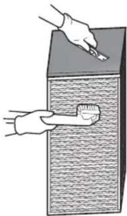
natural_image
Illustration of two hands cleaning a textured surface with a brush (no text or symbols)
natural_image
Illustration of a hand washing clothes in a basin with a magnifying glass above the sink (no text or symbols)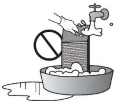
natural_image
Illustration of a hand washing a water-filled basin with a prohibition symbol, no text or labels presentTotal Heat ExchngerAir Filter
Assembly and Check after Maintenance
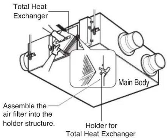
1. Assembly of Total heat exchanger
Securely put the corner parts (4 or 6 parts) of the Total heat exchanger into the holder for assembly and slide them into the inside of the main body.
text_image
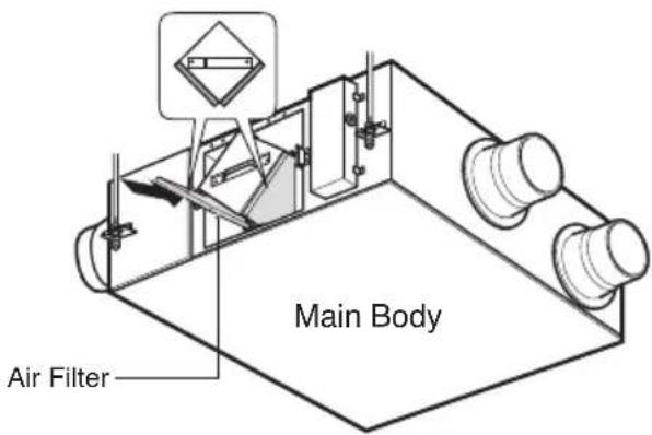
Total Heat Exchanger Main Body Assemble the air filter into the holder structure. Holder for Total Heat Exchanger2. Assembly of air filter
Assemble the air filter into the holder structure of the Total heat exchanger.
• Take care to ensure that surface of the Total heat exchanger could not be damaged.
• Dusts adhered to the Total heat exchanger may cause deterioration of Air volume.
text_image
Main Body Air Filter3. Assembly of maintenance cover
Fix the cover to the right hinge and fix it to the left side. (A nameplate is adhered toward the reading direction).

WARNING: Turn the breaker off when cleaning the product.

CAUTION: Gloves should be worn when doing the maintenance work.
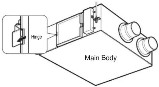
text_image
Hinge Main BodyCheck Item prior to notify a failure
| Symptom | Check Item | Counter-measure |
| The Product doesn't work | Is power not supplied? | Supply Power |
| The Product doesn't work through you press the 'ON' switch | Is Air Filter, Total heat exchanger clogged severely? | Follow cleaning and changing method. |
| Is the Indoor temperature less than -10°C or more than 45°C? | It's standby mode for protecting Total Heat Exchanger. | |
| Even though you change the fan speed, the operation mode doesn't change and it changes to 'Auto or Low' | Is the Indoor temperature less than -10°C or more than 45°C? | It's operation mode to protect Total Heat Exchanger. |
Operating Instructions (Accessory) ......10
natural_image
Simple line drawing of people enjoying a meal at a table with sun and palm trees in the background (no text or symbols)text_image
Technical diagram of an air duct system with numbered components for identificationtext_image
Technical diagram of a vehicle chassis with numbered components for identificationtext_image
Technical diagram of a vehicle chassis with numbered components for identificationtext_image
Technical diagram of a mechanical device with numbered components for identificationtext_image
2F H AIR FLOW SUB FUNC VENT OK CLEAR ESC TEMP FAN SPEED OPER MODE 1AM 1200natural_image
Illustration of two hands cleaning a textured wall with a brush (no text or symbols)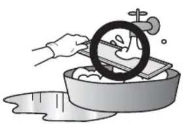
natural_image
Illustration of a hand washing clothes in a basin with a circular pipe and faucet (no text or symbols)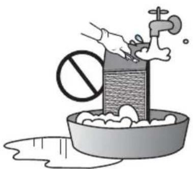
natural_image
Illustration of a hand washing a basin with a prohibition symbol and a faucet, no text or symbols present.natural_image
Simple line drawing of people enjoying a picnic at a table with sun and palm trees in the background (no text or symbols)text_image
Technical diagram of an air duct system with numbered components for identificationtext_image
Technical diagram of a mechanical or electrical enclosure with numbered components labeled 1 through 6.text_image
Technical diagram of a vehicle chassis with numbered components for identificationtext_image
Technical diagram of a mechanical device with numbered components for identificationtext_image
Technical diagram of a mechanical device with numbered components for identificationtext_image
ATIATION H AIR FLOW SUB FUNC VENT ▲ FAN SPEED TEMP ( ) OPER MODE 1200text_image
71 AIR LATER SUB FLOW FAN SPEED H 12:00 AIR FLOW SUB FUNC VENT ▲ FAN SPEED I OK CLEAR TEMP ▼ ( ) OPER MODE ESCnatural_image
Illustration of two hands cleaning a textured wall with a brush (no text or symbols)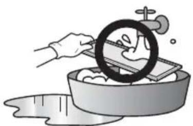
natural_image
Illustration of a hand washing clothes in a basin with a magnifying glass above the sink (no text or symbols)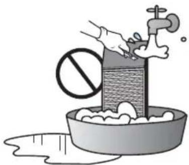
natural_image
Illustration of a hand washing a water pump with a prohibition symbol, next to a bowl of water and a pipe (no text or symbols)natural_image
Simple line drawing of people relaxing at a table with sun and palm trees in the background (no text or symbols)text_image
Technical diagram of a mechanical device with numbered components for identificationtext_image
Technical diagram of a mechanical or electrical enclosure with numbered components labeled 1 through 6.text_image
Technical diagram of a mechanical device with numbered components for identificationtext_image
Technical diagram of a mechanical device with numbered components for identificationtext_image
Technical diagram of a mechanical device with numbered components for identificationtext_image
HVILATES H 12:00 AIR FLOW SUB FUNC VENT OK CLEAR TEMP FAN SPEED OPER MODEnatural_image
Illustration of two hands cleaning a textured wall with a brush (no text or symbols)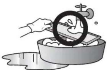
natural_image
Illustration of a hand washing clothes in a basin with a circular object above (no text or symbols)
natural_image
Illustration of a hand washing a faucet into a basin with a prohibition symbol (no text or labels)LESEN SIE DIESES HANDBUCH
natural_image
Illustration of people enjoying a meal at a table with sun and palm trees in the background (no text or symbols)Sicherheitshinweise
text_image
Technical diagram of a mechanical device with numbered components for identificationtext_image
Technical diagram of a mechanical ventilation system with numbered componentstext_image
Technical diagram of a mechanical device with numbered components for identificationtext_image
Technical diagram of a mechanical device with numbered components for identificationtext_image
Technical diagram of a mechanical device with numbered components for identificationtext_image
1 2 3 4 5 6 7 8 9 10 11 12 13 14 15 AIR FLOW SUB FUNC VENT OR CLEAR ESC TEMP FAN SPEED OPER MODEtext_image
12 SUB LABEL H N1 AIR FLOW SUB FUNC VENT VOLT OK CLEAR < > ESC FAN SPEED TEMP ( ) OPER MODE 12:00text_image
INTUATE SUPPORT C: CAN SUEL H AIR FLOW SUB FUNC VENT ▲ FAN SPEED ① TEMP ( ) OPER MODE ESC 1200natural_image
Illustration of a hand washing clothes in a basin with a circular object on top (no text or symbols)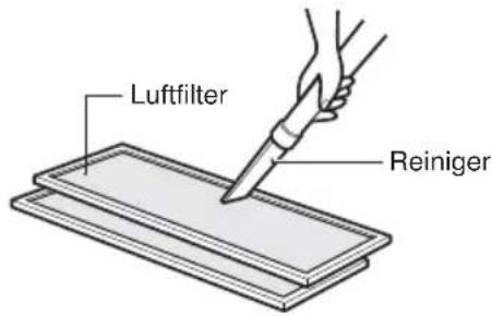
text_image
Luftfilter Reiniger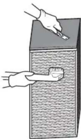
natural_image
Illustration of two hands cleaning a textured wall with a brush (no text or symbols)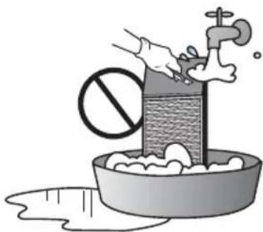
natural_image
Illustration of a hand washing a faucet with a prohibition symbol above it, next to a bowl of water and splashing liquid (no text or symbols)natural_image
Simple line drawing of people relaxing on a picnic table with sun and palm trees in the background (no text or symbols)text_image
Technical diagram of a mechanical device with numbered components for identificationtext_image
Technical diagram of a mechanical or electrical enclosure with numbered components labeled 1 through 6.text_image
Technical diagram of a vehicle chassis with numbered components for identificationtext_image
Technical diagram of a mechanical device with numbered components for identificationtext_image
Technical diagram of a vehicle chassis with numbered components for identificationtext_image
1 2 3 4 5 6 7 8 9 10 11 12 13 14 15 AIR FLOW SUB FUNC VOLT EX CLEAN ESC TEMP FAN SPEED OPER MODEtext_image
HV LOTH SUB FLOW H 12:00 AIR FLOW SUB FUNC VENT ▲ FAN SPEED ① TEMP ( ) OPER MODE OK CLEAR ▲ < > V ESCVentilation interlinked operation
natural_image
Illustration of a hand using a brush to clean or paint over a textured wall (no text or symbols)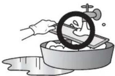
natural_image
Illustration of a hand washing dishes in a basin with a circular object above (no text or symbols)Φίλτρο αέρα
natural_image
Illustration of a hand washing a water pump with a prohibition symbol, next to a bowl of water and a splashing drop (no text or symbols)natural_image
Simple line drawing of people enjoying a picnic at a table with sun and palm trees (no text or symbols)text_image
Technical diagram of an air duct system with numbered components for identificationtext_image
Technical diagram of a mechanical ventilation system with numbered componentstext_image
Technical diagram of a vehicle chassis with numbered components for identificationtext_image
Technical diagram of a mechanical device with numbered components for identificationtext_image
Technical diagram of a mechanical device with numbered components for identificationnatural_image
Illustration of a hand using a brush to clean or store wood, with no visible text or symbols
natural_image
Illustration of a hand washing clothes in a basin with a magnifying glass (no text or symbols)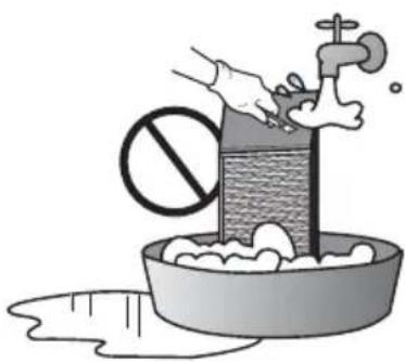
natural_image
Illustration of a hand washing a basin with a water pump and a prohibition symbol (no text or labels)3. Assembly of maintenance cover
Fix the cover to the right hinge and fix it to the left side. (A nameplate is adhered toward the reading direction).

text_image
Technical diagram of an air duct system with numbered components for identificationtext_image
Technical diagram of a mechanical ventilation system with numbered componentstext_image
Technical diagram of a vehicle chassis with numbered components for identificationtext_image
Technical diagram of a mechanical device with numbered components for identificationtext_image
Technical diagram of a mechanical device with numbered components for identificationtext_image
HV HV LATOR PER SHARE MAXIMUM H 12:00 AIR FLOW SUB FUNC VENT OK CLEAR ▲ ▼ ▲ FAN SPEED TEMP ( ) OPER MODEVentilation interlinked operation
text_image
7F CONTINUING EXCLUDING ANY ORDER H 12:00 AIR FLOW SUB FUNC VENT Δ OK CLEAR ▲ ▼ ESC FAN SPEED TEMP ( ) OPER MODEnatural_image
Diagram of a mechanical device with a circular component and a connecting rod, labeled 'Zorg voor' (no other text or symbols)- For service, always contact the dealer or an Authorized Service Center.
natural_image
Illustration of two hands cleaning a textured wall with a brush (no text or symbols)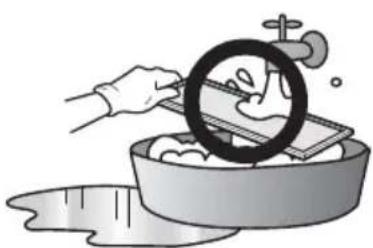
natural_image
Illustration of a hand washing dishes in a basin with a magnifying glass overlay (no text or symbols)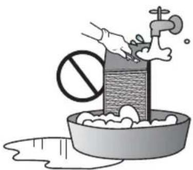
natural_image
Illustration of a hand washing a water dispenser with a prohibition symbol, next to a bowl of water and splashing liquid (no text or symbols)Totale Warmte-uitwisselaarLuchtfi
text_image
ego personneltext_image
Technical diagram of an air duct system with numbered components for identificationtext_image
Technical diagram of a mechanical ventilation system with numbered componentstext_image
Technical diagram of a vehicle chassis with numbered components for identificationtext_image
Technical diagram of a mechanical device with numbered components for identificationtext_image
Technical diagram of a mechanical device with numbered components for identificationtext_image
1 2 3 4 5 6 7 8 9 10 11 12 13 14 15 AIR FLOW SUB FLOW VEGET OK CLEAR ESC TEMP FAN SPEED OPER MODEtext_image
7T SELECT OPEN H 12:00 AIR FLOW SUB FUNC VENT Δ FAN SPEED OK CLEAR Δ TEMP ( ) OPER MODE ESCnatural_image
Illustration of a hand using a brush to clean or store wood, with no visible text or symbols
natural_image
Illustration of a hand washing clothes in a basin with a magnifying glass (no text or symbols)
natural_image
Illustration of a hand washing a basin with a water pump and a prohibition symbol (no text or labels)natural_image
Simple line drawing of people enjoying a picnic at a table with sun and palm trees in the background (no text or symbols)Măsuri de siguranță
- There is risk of fire or electric shock.
- There is risk of fire or electric shock.
- There is risk of fire or electric shock.
text_image
Technical diagram of a mechanical device with numbered components for identificationtext_image
Technical diagram of a mechanical ventilation system with numbered componentstext_image
Technical diagram of a vehicle chassis with numbered components for identificationtext_image
Technical diagram of a vehicle chassis with numbered components for identificationtext_image
Technical diagram of a mechanical device with numbered components for identificationtext_image
20°FLA H HV 12:00 AIR FLOW SUB FUNC VENT OK CLEAR Δ FAN SPEED TEMP ( ) OPER MODEtext_image
VENTILATION SUB FLOW H 12:00 AR FLOW SUB FUNC VENT OK CLEAR ▲ ▼ ESC FAN SPEED TEMP ( ) OPER MODEtext_image
U- Maintenance covertext_image
Total Heat ExchangerModele : LZ-H050GBA2 / LZ-H080GBA2 / LZ-H100GBA2
natural_image
Illustration of a hand using a brush to clean or store wood, with no visible text or symbols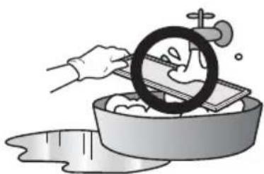
natural_image
Illustration of a hand washing clothes in a basin with a circular object on top (no text or symbols)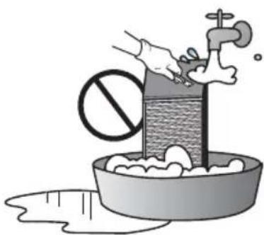
natural_image
Illustration of a hand washing a basin with a water stopper and a prohibition symbol (no text or labels)text_image
Technical diagram of an air duct system with numbered components for identificationtext_image
Technical diagram of a mechanical ventilation system with numbered componentstext_image
Technical diagram of a vehicle chassis with numbered components for identificationtext_image
Technical diagram of a mechanical device with numbered components for identificationtext_image
Technical diagram of a mechanical device with numbered components for identificationtext_image
AIR FLOW SUB FUNC VENT AIR FLOW SUB FUNC VENT OK CLEAR ▲ ▼ ▲ ▼ FAN SPEED TEMP ( ) OPER MODEtext_image
11 WIMPLETENS VOUTLINE FAN WIFE H 1 AM 12:00 AIR FLOW SUB FUNC VENT Δ FAN SPEED TEMP ( ) OPER MODEnatural_image
Diagram of a device with a circular component and a connecting rod, labeled 'Assegure-' (no other text or symbols)text_image
Corpo principaltext_image
Tampa de manutenção Corpo principal3. Retire o dissipador de calor Total
text_image
Corpo principalnatural_image
Illustration of hands using a tool to clean or brush a textured surface (no text or symbols)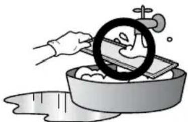
natural_image
Illustration of a hand washing clothes in a basin with a circular object on top (no text or symbols)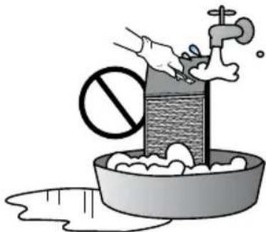
natural_image
Illustration of a hand washing a bathtub with a water pump and a prohibition symbol (no text or labels)Dissipador de Calor TotalFiltro de
text_image
Dobradica Corpo principalnatural_image
Simple line drawing of people enjoying a meal at a table with sun, palm tree, and cups (no text or symbols)text_image
Technical diagram of an air duct system with numbered components for identificationtext_image
Technical diagram of a mechanical ventilation system with numbered componentstext_image
Technical diagram of a vehicle chassis with numbered components for identificationtext_image
Technical diagram of a vehicle chassis with numbered components for identificationtext_image
Technical diagram of a mechanical device with numbered components for identificationnatural_image
Diagram of a mechanical device with a circular component and a connecting rod, labeled 'A használ' (no other text or symbols)natural_image
Illustration of two hands cleaning a textured surface with a brush (no text or symbols)
natural_image
Illustration of a hand washing clothes in a basin with a magnifying glass (no text or symbols)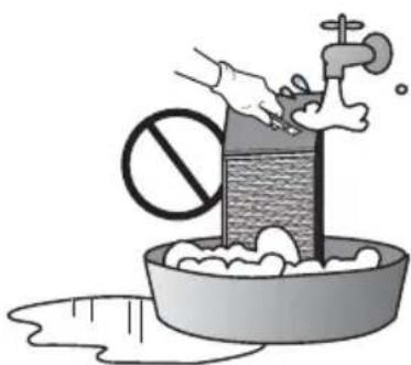
natural_image
Illustration of a hand washing a water bottle with a prohibition symbol, next to a bowl of soap and a faucet (no text or symbols)natural_image
Illustration of two people sitting on a table with circular objects and cups, no text or symbols presentМерки за безопасност
text_image
Technical diagram of an air duct system with numbered components for identificationtext_image
Technical diagram of a vehicle chassis with numbered components for identificationtext_image
Technical diagram of a mechanical device with numbered components for identificationtext_image
Technical diagram of a mechanical device with numbered components for identificationnatural_image
Illustration of a hand washing dishes with a magnifying glass (no text or symbols)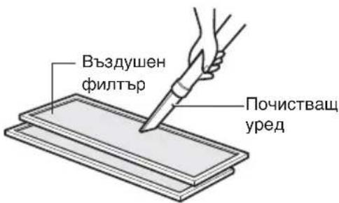
natural_image
Illustration of two hands cleaning a textured wall with a brush (no text or symbols)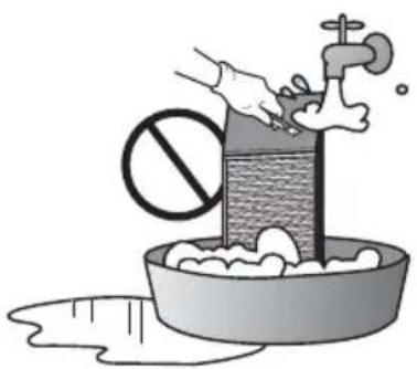
natural_image
Illustration of a hand washing a basin with a water-filled sink and a faucet, no text or symbols present.natural_image
Simple line drawing of a family enjoying a picnic at a table with sun, palm tree, and cups (no text or symbols)text_image
Technical diagram of a mechanical ventilation system with numbered components for identificationtext_image
Technical diagram of a mechanical ventilation system with numbered componentstext_image
Technical diagram of a vehicle chassis with numbered components for identificationtext_image
Technical diagram of a mechanical device with numbered components for identificationtext_image
Technical diagram of a mechanical device with numbered components for identification12 DUGME ZA NAGORE, NADOLE, ULEVO, UDESNO
- Da biste proverili sobnu temperaturu, pritisnite dugme ⬤.
13 DUGME ZA SOBNU TEMPER-ATURU
14 DUGME ZA PODEŠAVANJE/OTKAZIVANJE
15 DUGME ZA IZLAZ
text_image
20° PLATE H AIR FLOW SUB FUNC VENT Δ FAN SPEED OK CLEAR Δ TEMP ( ) OPER MODE ESC 12:00| Povezani rad sa ventilatorom | |
| 1 | Pritisnite dugme [IMAGE] na kontrolnog ploči daljinskog upravljača. 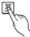 - Koristi se samo kada su klima uređaj i opšta ventilacija povezani. - Koristi se samo kada su klima uređaj i opšta ventilacija povezani. |
| 2 | Pritiskom na dugme „Start/Stop“ u režimu ventilacije uključuje se ventilacija. |
| 3 | Pritiskom na dugme [OPER MODE] menja se režim ventilacije. 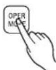 Pritiskom na dugme za izbor režima rada, režim se menja ovako : „Heat exchange → normal → automatic“※ Prikazuje se na displeju daljinskog upravljača kada je u režimu ventilacije, a prikazuje željenu temperaturu kada se vrati u režim klima uređaja. Pritiskom na dugme za izbor režima rada, režim se menja ovako : „Heat exchange → normal → automatic“※ Prikazuje se na displeju daljinskog upravljača kada je u režimu ventilacije, a prikazuje željenu temperaturu kada se vrati u režim klima uređaja. |
| 4 | Pritiskom na dugme [FAN SPEED] u opštem režimu ventilacije menja se brzina 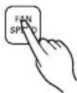 strujanja vazduha.Pritiskom na dugme za brzinu strujanja vazduha, menja se režim ovako: “weak → strong → extra strong”.Ako je instaliran senzor za CO2, može se birati između „slab → jak → veoma jak → automatski“. strujanja vazduha.Pritiskom na dugme za brzinu strujanja vazduha, menja se režim ovako: “weak → strong → extra strong”.Ako je instaliran senzor za CO2, može se birati između „slab → jak → veoma jak → automatski“. |
| 5 | Vraćanje na režim klima uređaja1)Automatsko vraćanje : Ako ne pritisnete nijedno dugme u roku od 15 sekundi ili duže, on se automatski vraća u režim klima uređaja.2) Ručno vraćanje : Pritiskom na dugme [RENT] u režimu ventilacije, ručno vraćate u taj režim. |
Način rada i odabir količine vazduha – jedan rad ventilacije.
text_image
Iaolja. UPITERATION SUB FLOW H III 1200 AR FLOW SUB FUNC VENT OK CLEAR ▲ ▼ ▲ FAN SPEED TEMP ( ) OPER MODEJedan rad ventilacije
natural_image
Diagram of a pre-upotre device with a circular component and cable, labeled 'Pre upotre' (no other text or symbols)OPREZ: Take care to ensure that you could not damage when taking the air filter out since there is a sharp part on it.
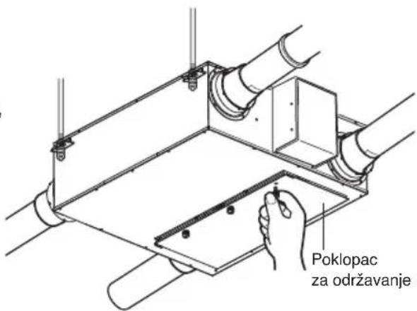
text_image
Poklopac za održavanje3. Izvadite izmenjivač ukupne toplote.
natural_image
Illustration of two hands cleaning a textured wall with a brush (no text or symbols)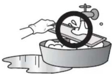
natural_image
Illustration of a hand washing clothes in a basin with a magnifying glass (no text or symbols)
natural_image
Illustration of a hand washing a basin with a water pump and a prohibition symbol (no text or labels)natural_image
Simple line drawing of a family enjoying a picnic at a table with sun, palm tree, and food items (no text or symbols)Mjere opreza
text_image
Technical diagram of a mechanical device with numbered components for identificationtext_image
Technical diagram of a mechanical ventilation system with numbered componentstext_image
Technical diagram of a vehicle chassis with numbered components for identification-
Poklopac prilikom održavanja
-
Filtar zraka
Sprječava prašinom izazvano začepljenje izmjenjivača ukupne topline.
text_image
Technical diagram of a mechanical device with numbered components for identification- Poklopac prilikom održavanja
- Filtar zraka
Sprječava prašinom izazvano začepljenje izmjenjivača ukupne topline.
text_image
Technical diagram of a device with numbered components, likely an electronic or mechanical assembly.- Poklopac prilikom održavanja
- Filtar zraka
Sprječava prašinom izazvano začepljenje izmjenjivača ukupne topline.
text_image
1 2 3 4 5 6 7 8 9 10 11 12 13 14 15 AIR FLOW SUB FLOW VENT EX OK CLEAR ESC TEMP FAN SPEED OPER MODEtext_image
20° PLATE H AIR FLOW SUB FUNC VENT Δ FAN SPEED OK CLEAR Δ TEMP ( ) OPER MODE ESC 12:00text_image
UNITIATION H HV HV HV HV HV HV HV HV HV HV HV HV HV HV HV HV HV HV HV HV HV HV HV HV HV HV HV HV HV HV HV HV HV HV HV HV HV HV HV HV HV HV HV HV HV HV HV HV HV HV VENT VENT VENT VENT VENT VENT VENT VENT VENT VENT VENT VENT VENT VENT VENT VENT VENT VENT VENT VENT VENT VENT VENT VENT VENT VENT VENT VENT VENT VENT VENT VENT VENT VENTSamo prozračivanje
natural_image
Illustration of a hand using a tool to clean or mark a textured surface, with another hand pointing at it (no text or symbols present)
natural_image
Illustration of a hand washing clothes in a basin with a magnifying glass (no text or symbols)
natural_image
Illustration of a hand washing a water bottle with a prohibition symbol, next to a bowl of soap and a faucet (no text or symbols)natural_image
Simple line drawing of people enjoying a picnic at a table with drinks and sun (no text or symbols)Säkerhetsinformation
text_image
Technical diagram of an air duct system with numbered components for identificationtext_image
Technical diagram of a mechanical ventilation system with numbered componentstext_image
Technical diagram of a vehicle chassis with numbered components for identificationtext_image
Technical diagram of a vehicle chassis with numbered components for identificationtext_image
Technical diagram of a mechanical device with numbered components for identificationtext_image
1 2 3 4 5 6 7 8 9 10 11 12 13 14 15 AIR FLOW SUB FUNC VENT EX CLEAR ESC TEMP FAN SPEED OPER MODEtext_image
71 MIN LATES H AIR FLOW SUB FUNC VENT ▲ ▲ ▲ ▲ FAN SPEED TEMP ( ) OPER MODE 1200natural_image
Illustration of a hand using a brush to clean or store wood, with no visible text or symbols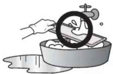
natural_image
Illustration of a hand washing dishes with a magnifying glass, no text or symbols present
natural_image
Illustration of a hand washing a basin with a water tap and a prohibition symbol (no text or labels)natural_image
Simple line drawing of a family enjoying a picnic at a table with sun and palm trees (no text or symbols)Sikkerhetsforskrifter
text_image
Technical diagram of an air duct system with numbered components for identificationtext_image
Technical diagram of a mechanical ventilation system with numbered componentstext_image
Technical diagram of a vehicle chassis with numbered components for identification-
Vedlikeholdsdeksel
-
Luftfilter
text_image
Technical diagram of a vehicle chassis with numbered components for identification- Vedlikeholdsdeksel
- Luftfilter
text_image
Technical diagram of a device with numbered parts labeled 1 through 8, showing internal components like monitors, gears, and a motor.- Vedlikeholdsdeksel
- Luftfilter
text_image
1 2 3 4 5 6 7 8 9 10 11 12 13 14 15 AIR FLOW SUB FLOW VENT OK CLEAR ESC TEMP FAN SPEED OPER MODEtext_image
UNITIATION H H 1200 AIR FLOW SUB FUNC VENT OK CLEAR TEMP FAN SPEED OPER MODEnatural_image
Diagram of a mechanical device with a circular component and a connecting rod, labeled 'Påse at pr' (no other text or symbols)natural_image
Illustration of a hand using a tool to clean or mark a textured surface, with another hand pointing at it (no text or symbols present)
natural_image
Illustration of a hand washing clothes in a basin with a magnifying glass (no text or symbols)
natural_image
Illustration of a hand washing a basin with a water tap and a prohibition symbol (no text or labels)Total varmevekslerLuftfilter
natural_image
Simple line drawing of people enjoying a meal at a table with sun and palm trees in the background (no text or symbols)Turvaohjeet
text_image
Technical diagram of a mechanical device with numbered components for identification- Tuloilman puhallin
text_image
Technical diagram of a mechanical ventilation system with numbered components- Tuloilman puhallin
text_image
Technical diagram of a vehicle chassis with numbered components for identificationtext_image
Technical diagram of a mechanical device with numbered components for identificationtext_image
Technical diagram of a mechanical device with numbered components for identificationnatural_image
Diagram of a Varmista etta device with a circular component and connecting rod (no text or symbols on the diagram itself)natural_image
Illustration of a hand using a brush to clean or store wood, with no visible text or symbols
natural_image
Illustration of a hand washing clothes in a basin with a circular object above (no text or symbols)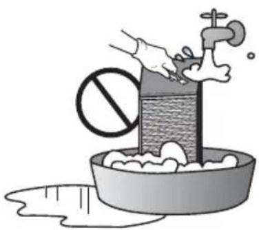
natural_image
Illustration of a hand washing a basin with a water pump and a prohibition symbol (no text or labels)natural_image
Simple line drawing of a family enjoying a picnic at a table with sun and palm trees (no text or symbols)text_image
Technical diagram of a mechanical device with numbered components for identificationtext_image
Technical diagram of a mechanical ventilation system with numbered components for identificationtext_image
Technical diagram of a vehicle chassis with numbered components for identificationtext_image
Technical diagram of a mechanical device with numbered components for identificationtext_image
Technical diagram of a mechanical device with numbered components for identificationtext_image
1 2 3 4 5 6 7 8 9 10 11 12 13 14 15 AIR FLOW SUB FLOW VENT OK CLEAN ESC TEMP FAN SPEED OPER MODEtext_image
Luftfilter Renser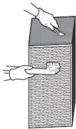
natural_image
Illustration of a hand using a brush to clean or store wood, with no visible text or symbols
natural_image
Illustration of a hand washing clothes in a basin with a magnifying glass (no text or symbols)
natural_image
Illustration of a hand washing a basin with a water tap and a prohibition symbol (no text or labels)Samlet varmevekslerLuftfilter