PHET 15 C2 - Electric stapler PARKSIDE - Free user manual and instructions
Find the device manual for free PHET 15 C2 PARKSIDE in PDF.

User questions about PHET 15 C2 PARKSIDE
0 question about this device. Answer the ones you know or ask your own.
Ask a new question about this device
Download the instructions for your Electric stapler in PDF format for free! Find your manual PHET 15 C2 - PARKSIDE and take your electronic device back in hand. On this page are published all the documents necessary for the use of your device. PHET 15 C2 by PARKSIDE.
USER MANUAL PHET 15 C2 PARKSIDE
natural_image
Abstract arrangement of five gray rectangular shapes on white background (no text or symbols)
natural_image
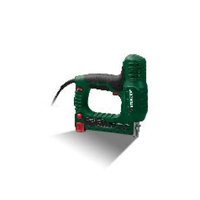
Exterior view of a black Parkside electric drill kit (no signage or text on body)ELEKTROTACKER UND -NAGLER/ELECTRIC TACKER AND NAILER/AGRAFEUSE-CLOUEUSE ÉLECTRIQUE PHET 15 C2
DE AT CH
ELEKTROTACKER UND -NAGLER
ELEKTRYCZNY ZSZYWACZ I GWOŹDZIARKA
Translation of the original instructions
NL BE
ELEKTRISCHE TACKER VOOR NIETEN EN SPIJKERS
natural_image
Abstract black-and-white graphic with a checkmark above a textured surface (no text or symbols)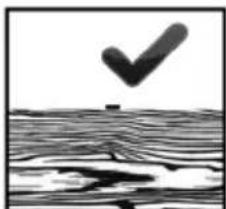
natural_image
Abstract black-and-white graphic with a checkmark above a wavy surface (no text or symbols)natural_image
Simple black-and-white diagram showing a cross symbol above a rectangular frame over a wavy surface (no text or labels)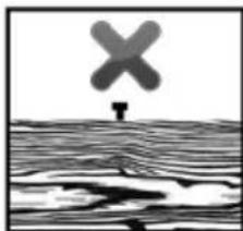
natural_image
Black-and-white illustration of a cross symbol above a wavy surface, no text or symbols presentIntended use Page 18
Parts description......Page 19
Scope of delivery ......Page 19
Technical data......Page 19
General power tools safety warnings......Page 20
Tacker safety warnings ......Page 21
Supplementary notes......Page 22
Original accessories/auxiliary equipment......Page 22
Initial use ......Page 22
Adding staples....Page 22
Adding nails Page 22
Functions......Page 23
Stapling and nailing......Page 23
Clearing jammed staples or nails......Page 23
Choosing the correct length of nails and staples ......Page 23
Cleaning and care......Page 24
Maintenance ......Page 24
Repair......Page 24
Storage Page 24
Disposal Page 24
Warranty and service Page 25
Warranty Page 25
Warranty claim procedure......Page 25
Service Page 26
EU declaration of conformity ......Page 27
| List of pictograms used | |||
  | Please read the instructions for use. The instructions for use contain additional information. |  | Protect the product from moisture. |
 | Read the instruction manual. Alternating current/voltage | ||
 | Wear eye protection. | Follow the warnings and safety notes! | |
 | Wear hearing protection. Risk of el |  shock! shock! | |
 | For use in dry indoor locations only. |  | Switch off the product and disconnect it from the mains before making any adjustments, performing maintenance, cleaning and when the product is not in use. |
 | Protection class II (double insulation) |  | CE mark indicates conformity with relevant EU directives applicable for this product. |
 | Safety information Instructions for use | ||
Electric tacker and nailer
- Introduction

We congratulate you on the purchase of your new product. You have chosen a high quality product. The instructions for use are part of the product. They contain important information concerning safety, use and disposal. Before using the product, please familiarise yourself with all of the safety information and instructions for use. Only use the product as described and for the specified applications. If you pass the product on to anyone else, please ensure that you also pass on all the documentation with it.
Intendeduse
This product is intended for fastening paperboard, sheets of paper, leather, insulation, fabric and similar materials onto soft wood (real wood), plywood boards having similar hardness as soft-wood and low density fiberboard. It is only intended for private household use. Any other use or modification of the product shall be considered improper use and may result in serious accident hazards. The manufacturer is not liable for any damages caused by improper use. Not intended for commercial use. This product is not intended for securing electrical cables.
Partsdescription
1 Switch lock
2 Trigger
3 Push rod
3a Release button
4 Magazine
5 Fillindicator
(staples)
6 Safety contact
7 Fillindicator (staples and nails)
- Scope of delivery
1 Electric tacker and nailer
400 Staples, 10mm
100 Nails, 14mm
1 Operating instructions
- Technicaldata
Electric tacker
and nailer: PHET 15 C2
Modelnumber:HG12187
Rated input voltage: 230–240V\~, 50Hz
Rated current: 4A
Speed: max. 20min -1
Magazine capacity: 100 staples or 50 nails
Protection class: II/□(double insulation)
Wire staples:
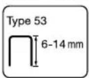
Staple width: 11.4mm
Staple length: 6–14mm
Nails:
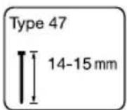
Nail length: 14–15 mm
Noise emission value:
The measured values for sound comply with EN 60745. The A-weighted single-event noise level, standardised to 1s, is typically:
Sound pressure level ( L_p ): 85.3 dB
Sound power level ( L_WA ): 96.3dB
Uncertainty ( L_pA , L_WA ): 3 dB

Wear hearing protection!
Vibration values determined in accordance with EN 60745:
Vibration emission value a_h = 3.159 m/s^2
Uncertainty K = 1.5 m/s ^4
Note: The vibration level specified in these instructions has been measured in accordance with a standardized measuring procedure specified in EN 60745 and can be used for equipment comparisons. The specified vibration emission value can also be used to make an initial exposure estimate.
WARNING!
The vibration level varies in accordance with the use of the power tool and may be higher than the value specified in these instructions in some cases. Regular use of the electric tool in such a way may cause the users to underestimate the vibration. Try to keep the vibration loads as low as possible. Measures to reduce the vibration load are, e.g. wearing gloves and limiting the working time. All states of operation must be taken into account (e.g. time when the power tool is switched off and time where the power tool is switched on but running without load).
Note: For an accurate estimate of the vibration load during a specific working period, the periods during which the appliance is switched off or is running but not actually being used must also be taken into consideration. This can significantly reduce the vibration load over the total working period.
● General power tools safety warnings

WARNING!

Read all safety directions and instructions. Failure to follow the warnings and instructions may result in electric shock, fire and/or serious injury.
Save all warnings and instructions for future reference.
The term “power tool” in the warnings refers to your mains-operated (corded) power tool or battery-operated (cordless) power tool.
Work area safety
a) Keep work area clean and well lit. Cluttered or dark areas invite accidents.
b) Do not operate power tools in explosive atmospheres, such as in the presence of flammable liquids, gases or dust. Power tools create sparks which may ignite the dust or fumes.
c) Keep children and bystanders away while operating a power tool.
Distractions can cause you to lose control.
Electrical safety
a) Power tool plugs must match the outlet. Never modify the plug in any way. Do not use any adapter plugs with earthed (grounded) power tools. Unmodified plugs and matching outlets will reduce risk of electric shock.
b) Avoid body contact with earthed or grounded surfaces, such as pipes, radiators, ranges and refrigerators.
There is an increased risk of electric shock if your body is earthed or grounded.
c) Do not expose power tools to rain or wet conditions. Water entering a power tool will increase the risk of electric shock.
d) Do not abuse the cord. Never use the cord for carrying, pulling or unplugging the power tool. Keep cord away from heat, oil, sharp edges or moving parts. Damaged or entangled cords increase the risk of electric shock.
e) When operating a power tool outdoors, use an extension cord suitable for outdoor use. Use of a cord suitable for outdoor use reduces the risk of electric shock.
f) If operating a power tool in a damp location is unavoidable, use a residual current device (RCD) protected supply. Use of an RCD reduces the risk of electric shock.
Personal safety
a) Stay alert, watch what you are doing and use common sense when operating a power tool. Do not use a power tool while you are tired or under the influence of drugs, alcohol or medication. A moment of inattention while operating power tools may result in serious personal injury.
b) Use personal protective equipment. Always wear eye protection.
Protective equipment such as dust mask, non-skid safety shoes, hard hat, or hearing protection used for appropriate conditions will reduce personal injuries.
c) Prevent unintentional starting. Ensure the switch is in the off-position before connecting to power source and/or battery pack, picking up or carrying the tool. Carrying power tools with your finger on the switch or energising power tools that have the switch on invites accidents.
d)R remove any adjusting key or wrench before turning the power tool on.
A wrench or a key left attached to a rotating part of the power tool may result in personal injury.
e) Do not overreach. Keep proper footing and balance at all times.
This enables better control of the power tool in unexpected situations.
f) Dress properly. Do not wear loose clothing or jewellery. Keep your hair, clothing and gloves away from moving parts. Loose clothes, jewellery or long hair can be caught in moving parts.
g) If devices are provided for the connection of dust extraction and collection facilities, ensure these are connected and properly used. Use of dust collection can reduce dust-related hazards.
Power tool use and care
a) Do not force the power tool. Use the correct power tool for your application. The correct power tool will do the job better and safer at the rate for which it was designed.
b) Do not use the power tool if the switch does not turn it on and off. Any power tool that cannot be controlled with the switch is dangerous and must be repaired.
c) Disconnect the plug from the power source and/or the battery pack from the power tool before making any adjustments changing accessories, or storing power tools. Such preventive safety measures reduce the risk of starting the power tool accidentally.
d) Store idle power tools out of the reach of children. Do not allow persons unfamiliar with the power tool or these instructions to operate the power tool. Power tools are dangerous in the hands of untrained users.
e) Maintain power tools. Check for misalignment or binding of moving parts, breakage of parts and any other condition that may affect the power tool's operation. If damaged, have the power tool repaired before use. Many accidents are caused by poorly maintained power tools.
f) Keep cutting tools sharp and clean. Properly maintained cutting tools with sharp cutting edges are less likely to bind and are easier to control.
g) Use the power tool, accessories and tool bits etc. in accordance with these instructions, taking into account the working conditions and the work to be performed. Use of the power tool for operations different from those intended could result in a hazardous situation.
Service
a) Have your power tool serviced by a qualified repair person using only identical replacement parts. This will ensure that the safety of the power tool is maintained.
• Tacker safety warnings
- Always assume that the tool contains fasteners. Careless handling of the tacker can result in unexpected firing of fasteners and personal injury.
- Do not point the tool towards yourself or anyone nearby. Unexpected triggering will discharge the fastener causing an injury.
-
Do not actuate the tool unless the tool is placed firmly against the workpiece. If the tool is not in contact with the workpiece, the fastener may be deflected away from your target.
-
Disconnect the tool from the power source when the fastener jams in the tool. While removing a jammed fastener, the tacker may be accidentally activated if it is plugged in.
- Use caution while removing a jamme fastener. The mechanism may be under compression and the fastener may be forcefully discharged while attempting to free a jammed condition.
- Do not use this tacker for fastening electrical cables. It is not designed for electric cable installation and may damage the insulation of electric cables thereby causing electric shock or fire hazards.
●Supplementarynotes
WARNING! RISK OF INJURY!
■ Never aim the appliance towards yourself or other people or animals.
- Ensure that no other people or animals are on the other side of the workpiece or in the immediate vicinity.

PROTECT YOUR EYES!
■ Wear safety goggles. This also applies to people who are carrying out support and holding work during operation.
- Secure the workpiece! A workpiece securely held by a clamping device or vice is much safer than one held in your hand.
■ Always guide the power cord away to the rear of the appliance.
●Originalaccessories/auxiliary equipment
■ Only use the accessories and additional equipment which are specified in the operating instructions and compatible with the appliance.
-Initialuse
WARNING!
Always activate switch lock 1 to lock the trigger 2 and disconnect the product from the mains before starting any works on the product.
- Addingstaples
□ Turn the product over.
☐ Squeeze the release button 3a (see Fig. B).
☐ Then pull out the push rod 3 from magazine 4 (see Fig. B).
☐ Add staples to the magazine 4 (see Fig. C).
After adding staples, slide the push rod 3 back to the magazine 4 till it is closed. Release button 3a must click and lock in place with the magazine 4 properly (see Fig. C).
Note: Use the window on the fill indicator 5 or 7 to check if the magazine 4 is empty. You can use both fill indicators to check whether there are still staples in the magazine.
- Addingnails
☐ Turn the product over.
☐ Squeeze the release button 3a (see Fig. B).
☐ Then pull out the push rod 3 from magazine 4 (see Fig. B).
☐ Follow icon shown on push rod 3 and add nails to the magazine 4 (see Fig. D).
After adding nails, slide the push rod 3 back to the magazine 4 till it is closed. Release button 3a must click and lock in place with the magazine 4 properly (see Fig. D).
Note: Use the window on the fill indicator 7 to check if the magazine 4 is empty.
●Functions
• Stapling and nailing
☐ Press down switch lock 1 completely from right to left to unlock position 🔒.
☐ Press the safety contact 6 into the work piece (see Fig. E).
☐ Squeeze the switch trigger ② whilst holding the product against the work piece to drive a staple/nail into it.
Note: Hold product firmly and press on work surface before firing to ensure complete penetration of the staple/nail.
●Clearingjammed staples or nails
WARNING!
Always activate switch lock 1 to lock the trigger 2 and disconnect the product from the mains before starting any works on the product.
Open the magazine 4 and pull out the push rod 3.
☐ Remove the jammed staple or nail from the magazine 4.
- Choosing the correct length of nails and staples
☐ Consider 2 factors to choose the correct length for staples and nails: - the thickness of the material to be fastened - the composition and hardness of the base material.
Typical examples
| Base material | Material to be fastened/thickness | Staples Nails | |
| Plywood ≤ 1mm 6–8 | mm | 8–10mm | |
| Fibre board | 1–3mm | 8–10mm | 12–14mm |
| Softwood (e.g. pine) | ≤ 3mm | 8–10mm | 10–12mm |
| 3–5mm | 10–14mm | 12–15mm | |

natural_image
Black-and-white illustration of a checkmark above a textured surface (no text or symbols)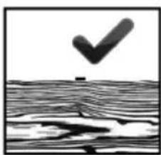
natural_image
Black and white illustration of a checkmark above a textured surface (no text or symbols)The crown of the staple or head of the nail should be flushed with the top of the material being fastened as shown.
natural_image
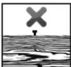
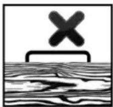
Simple black-and-white diagram showing a cross symbol above a wooden plank (no text or labels)
natural_image
Black-and-white illustration of a person standing on water with a large 'X' symbol above, no text or symbols present.If the crown of the staple or head of the nail is not flush with the top of the material being fastened, it means it is too long. In this case, use the next shorter staple or nail for optimal results.
- Cleaning and care
WARNING!
Always activate switch lock 1 to lock the trigger 2 and disconnect the product from the mains before starting any works on the product.
- Do not use chemical, alkaline, abrasive or other aggressive detergents or disinfectants to clean this product as they might be harmful to its surfaces.
■ Never allow fluids to get into the product.
■ The product must always be kept clean, dry and free from oil or grease.
■ Remove debris from it after each use and before storage.
■ Regular and proper cleaning will help ensure safe use and prolong the life of the product.
If the power cord needs to be replaced, this must be carried out by the manufacturer or an official representative in order to avoid safety hazards.
☐ Use a soft brush for areas that are hard to reach.
□ Clean the product with a dry cloth.
- Maintenance
WARNING!
Always activate switch lock 1 to lock the trigger 2 and disconnect the product from the mains before starting any works on the product.
■ The product is maintenance-free.
■ Before and after each use, check the product for wear and damage.
Repair
This product does not contain any parts that can be repaired by the user. Contact an authorised service centre or a similarly qualified person to have it checked and repaired.
Storage
■ Clean the product as described above.
■ Remove staples or nails from magazine 4 and activate switch lock 1 to lock the trigger 2 before storage.
■ Store the product, nails and staples in a dry, frost-free and well-ventilated place.
■ Always store the product in a place that is inaccessible to children.
●Disposal
The packaging is made entirely of recyclable materials, which you may dispose of at local recycling facilities.
Observe the marking of the packaging materials for waste separation, which are marked with abbreviations (a) and numbers (b) with following meaning: 1–7: plastics/20–22: paper and fibreboard/80–98: composite materials.
Contact your local refuse disposal authority for more details of how to dispose of your worn-out product.
To help protect the environment, please dispose of the product properly when it has reached the end of its useful life and not in the household waste. Information on collection points and their opening hours can be obtained from your local authority.
The product incl. accessories, manual and packaging materials are recyclable and are subject to extended producer responsibility. Dispose them separately, following the illustrated Info-tri (sorting information), for better waste treatment.
● Warranty and service
Warranty
The product has been manufactured to strict quality guidelines and meticulously examined before delivery. In the event of material or manufacturing defects you have legal rights against the retailer of this product. Your legal rights are not limited in any way by our warranty detailed below.
The warranty for this product is 3 years from the date of purchase. The warranty period begins on the date of purchase. Keep the original sales receipt in a safe location as this document is required as proof of purchase.
Any damage or defects already present at the time of purchase must be reported without delay after unpacking the product.
Should the product show any fault in materials or manufacture within 3 years from the date of purchase, we will repair or replace it – at our choice – free of charge to you. The warranty period is not extended as a result of a claim being granted. This also applies to replaced and repaired parts. This warranty becomes void if the product has been damaged, or used or maintained improperly.
The warranty covers material or manufacturing defects. This warranty does not cover product parts subject to normal wear and tear, thus considered consumables (e.g. batteries, rechargeable batteries, tubes, cartridges), nor damage to fragile parts, e.g. switches or glass parts.
- Warranty claim procedure
So that your request can be processed quickly, please observe the following instructions:
For all inquiries, please have the receipt and item number (IAN 465696_2404) ready as proof of purchase.
o The article number can be taken from the identification label on the product, engraving on the product, the front cover of your manual (at the bottom left), or the sticker on the back or bottom of the product.
o If malfunctions or other defects arise, first contact the service department indicated below by phone or email.
o You can then send a product recorded as defective to the communicated service address postage-free, making sure to enclose proof of purchase (receipt) and information on the details of the defect and when it occurred.
0

text_image
PDF ONLINE parkside-diy.comYou can download and view this and numerous other manuals at parkside-diy.com. This QR code takes you
directly to parkside-diy.com. Choose your country and use the search screen to search for the operating instructions. Entering the item number (IAN) 465696_2404 takes you to the operating instructions for your item.
Service
WARNING!
■ Have your product repaired at the service centre or an electrician, using only original manufacturer parts. This will maintain the safety of this product.
GB Service Great Britain
Tel.: 0800 0569216
E-Mail: owim@lidl.co.uk
IE Service Ireland
Tel.:1800200736
E-Mail: owim@lidl.ie
CE
• EU declaration of conformity
EU DECLARATION OF CONFORMITY (No. 465696_2404)
| IAN: | 465696_2404 |
| Product identification: | "PARKSIDE" Electric tacker and nailer |
| Model Number: | HG12187 |
The object of the declaration described above is in conformity with the relevant Union harmonisation legislation:
| Directive 2006/42/EC |
| Directive 2014/30/EU |
| Directive 2011/65/EU and all related amendments |
References to the relevant harmonised standards used or references to the other technical specifications in relation to which conformity is declared:
| N° / Parts |
| Directive 2006/42/EC |
| EN 60745-1:2009/A11:2010 |
| EN 60745-2-16:2010 |
| Directive 2014/30/EU |
| EN IEC 55014-1:2021 |
| EN IEC 55014-2:2021 |
| EN IEC 61000-3-2:2019/A1:2021 |
| EN 61000-3-3:2013/A2:2021 |
The object of the declaration described above is in conformity with Directive 2011/65/EU of the European Parliament and of the Council of 8 June 2011 on the restriction of the use of certain hazardous substances in electrical and electronic equipment:
| N° / Parts |
| Directive 2011/65/EU |
| EN IEC 63000:2018 |
Keeper of the technical documentation: OWIM GmbH & Co.KG
Signed for and on behalf of:
This declaration of conformity is issued under the sole responsibility of the manufacturer.
Translation of the original declaration of conformity
| Neckarsulm | 15.08.2024 | ||
| Place | Date | ppa. Stefan HaenselAuthorised Signatory | ppa. Jens BuchheimAuthorised Signatory |
natural_image
Abstract black-and-white graphic with a checkmark above a wavy line, no text or symbols present.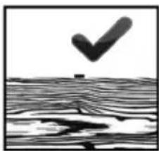
natural_image
Abstract black-and-white graphic with a downward arrow and wavy lines, no text or symbols present.natural_image
Simple black-and-white diagram showing a cross above a rectangular structure with wavy bottom lines (no text or symbols)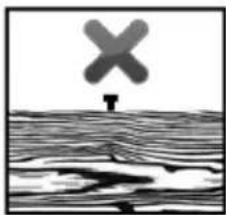
natural_image
Black-and-white illustration of a cross symbol above a wavy surface, no text or symbols presentWAARSCHUWING! GEVAAR VOOR LETSEL!
natural_image
Abstract black-and-white graphic with a checkmark above a textured surface (no text or symbols)
natural_image
Abstract black-and-white graphic with a downward arrow and wavy lines, no text or symbols present.natural_image
Simple black-and-white diagram showing a cross symbol above a rectangular frame, with no text or labels present.
natural_image
Black-and-white illustration of a person standing on a wavy surface with a large 'X' symbol above (no text or symbols present)natural_image
Black-and-white illustration of a checkmark above a wavy surface (no text or symbols)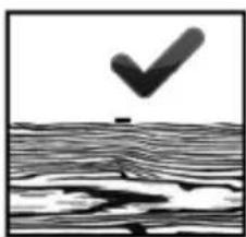
natural_image
Abstract black-and-white graphic with a downward arrow and wavy lines, no text or symbols present.natural_image
Simple line drawing of a cross-shaped object above a textured surface (no text or symbols)
natural_image
Black-and-white illustration of a cross symbol above a wavy surface, no text or symbols presentnatural_image
Black-and-white illustration of a checkmark above a wavy surface (no text or symbols)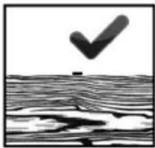
natural_image
Black and white abstract image with a downward arrow above a textured surface (no text or symbols)natural_image
Simple black-and-white diagram showing a cross symbol above a rectangular frame, with no text or labels present.
natural_image
Abstract black-and-white illustration of a cross symbol emerging from a wavy surface, with no text or symbols present.natural_image
Abstract black-and-white graphic with a checkmark above a wavy line pattern (no text or symbols)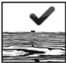
natural_image
Abstract black-and-white graphic with a downward arrow and wavy texture, no text or symbols present.natural_image
Simple black-and-white diagram showing a cross symbol above a wooden surface with wavy lines below (no text or labels)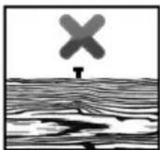
natural_image
Abstract grayscale illustration of a cross symbol above a wavy surface, no text or symbols presentnatural_image
Two identical black-and-white diagrams showing a checkmark above a textured surface, with no text or symbols present.natural_image
Two identical diagrams showing a cross symbol above a wavy surface and a small object below, both without any text or labels.Reparation ......Side 106
Opbevaring....Side 106
Bortskaffelse....Side 107
natural_image
Black checkmark above a wavy surface, no text or symbols present
natural_image
Abstract black-and-white graphic with a downward arrow and wavy texture, no text or symbols present.natural_image
Simple black-and-white diagram showing a cross symbol above a wavy line, no text or labels present.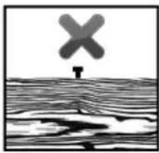
natural_image
Black-and-white illustration of a cross symbol above a wavy surface, no text or symbols presentacustica ( L_pA ): 85,3dB
natural_image
Black-and-white illustration of a checkmark above a textured surface (no text or symbols)
natural_image
Abstract black-and-white graphic with a downward arrow and wavy lines, no text or symbols present.natural_image
Simple black-and-white diagram showing a cross above a wooden surface with wavy lines (no text or symbols)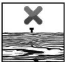
natural_image
Black-and-white illustration of a person standing on water with a large 'X' symbol above, no text or symbols present.natural_image
Black checkmark over a wavy surface, no text or symbols present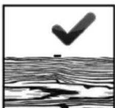
natural_image
Abstract black-and-white graphic with a checkmark above a wavy surface (no text or symbols)natural_image
Simple line drawing of a cross-shaped object above a wavy surface (no text or symbols)