CTH 26L H Class - Vacuum Cleaner FESTOOL - Free user manual and instructions
Find the device manual for free CTH 26L H Class FESTOOL in PDF.
| Brand | Festool |
| Model | CTH 26L H Class |
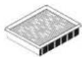
| Product type | H class mobile vacuum cleaner |
| Dust category | H (harmful dust, asbestos) |
| Tank volume | 26 litres |
| Power consumption | 350 - 1000 W |
| Max. connection to appliance socket (EU) | 2400 W |
| Max. volumetric flow | 234 m³/h |
| Max. depression | 24,000 Pa |
| Filter surface | 6,318 cm² |
| Suction hose length | 3.5 m, antistatic |
| Power cable length | 7.5 m |
| Sound level | 71 dB(A) |
| Protection rating | IP X4 |
| Dimensions (L x W x H) | 630 x 365 x 540 mm |
| Weight | 13.9 kg |
| Main functions | Dry and wet vacuuming, power regulation, automatic socket, flow monitoring, parking brake |
| Maintenance and cleaning | Replacement of filter bag and main filter, cleaning of tank |
| Safety | Thermal protection, automatic shutdown at maximum liquid level, antistatic system |
| Spare parts and repairability | Filter bags (SC-FIS-CT26/48), safety filter bags (FIS-CTH26/48), main filter, modules (pneumatic, socket); repair by Festool authorized service center, annual technical inspection recommended |
| General information | Compliant with EN 60335-2-69 for carcinogenic dust, asbestos and water; industrial use |
Frequently Asked Questions - CTH 26L H Class FESTOOL
User questions about CTH 26L H Class FESTOOL
0 question about this device. Answer the ones you know or ask your own.
Ask a new question about this device
Download the instructions for your Vacuum Cleaner in PDF format for free! Find your manual CTH 26L H Class - FESTOOL and take your electronic device back in hand. On this page are published all the documents necessary for the use of your device. CTH 26L H Class by FESTOOL.
USER MANUAL CTH 26L H Class FESTOOL
natural_image
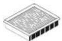
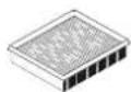
Two industrial vacuum cleaner units shown from front and side views (no visible text or symbols)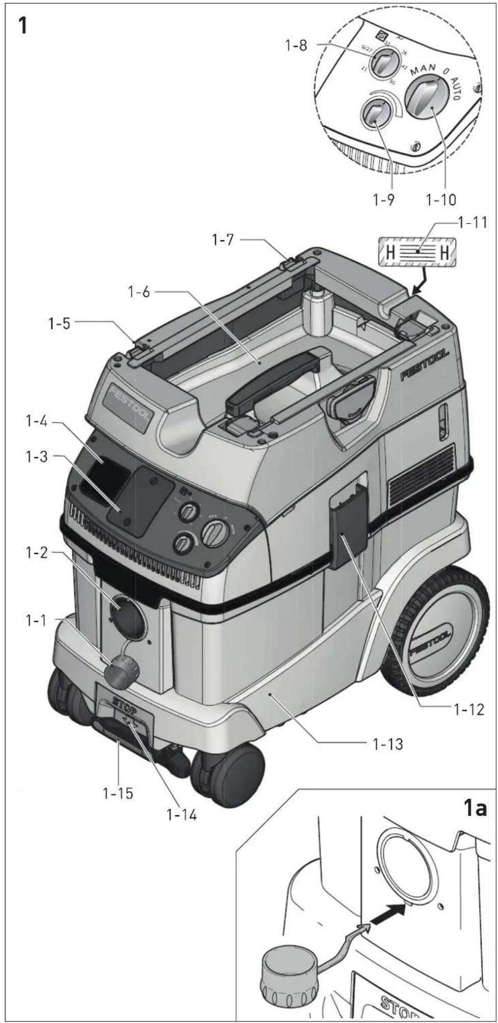
natural_image
Technical line drawing of a mobile phone driver with rear-mounted sensors and cable (no text or symbols)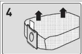
natural_image
Diagram of a rectangular container with two upward arrows indicating direction (no text or symbols)
natural_image
Diagram of a mechanical device with directional arrows indicating motion or movement (no text or symbols)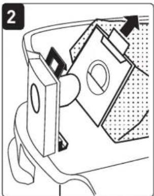
natural_image
Mechanical assembly diagram showing a component being inserted into a housing (no text or symbols visible)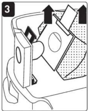
natural_image
Diagram of a mechanical device with directional arrows indicating movement or force (no text or symbols present)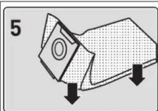
natural_image
Diagram of a mechanical component with downward arrows indicating force or movement (no text or symbols)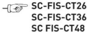
natural_image
Mechanical assembly diagram showing a component with arrows indicating motion or force direction (no text or symbols present)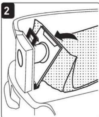
natural_image
Technical diagram of a mechanical component with directional arrows indicating movement (no text or symbols)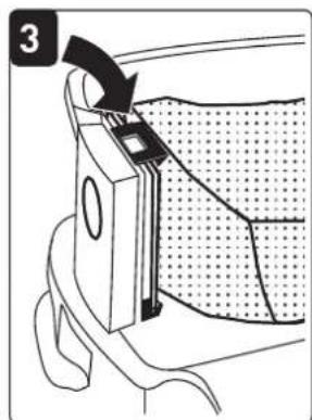
natural_image
Diagram of a mechanical component with a curved arrow indicating rotation, no text or symbols present

natural_image
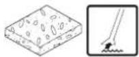
Line drawing of a car interior with luggage and a textured surface (no text or symbols)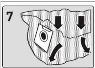
natural_image
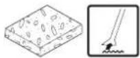
Diagram showing a hand holding a tool near a water surface, with no visible text or symbols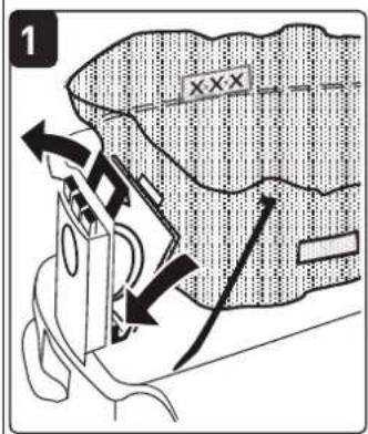
natural_image
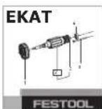
Illustration of a micrometer needle inserted into a grid notebook (no text or symbols visible)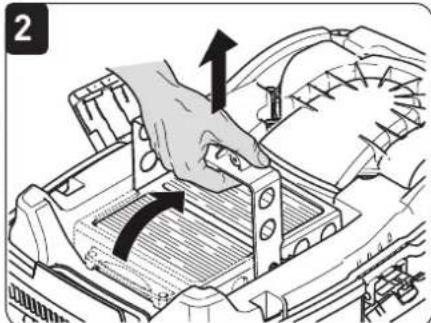
natural_image
Diagram of a hand pressing down on a vehicle engine compartment with directional arrows indicating motion (no text or symbols)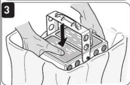
natural_image
Illustration of hands assembling a mechanical component with a black arrow indicating force direction (no text or symbols)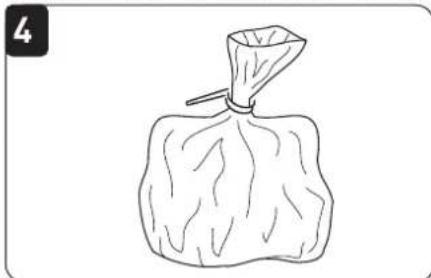
natural_image
Simple line drawing of a bag with visible roots and a handle (no text or symbols)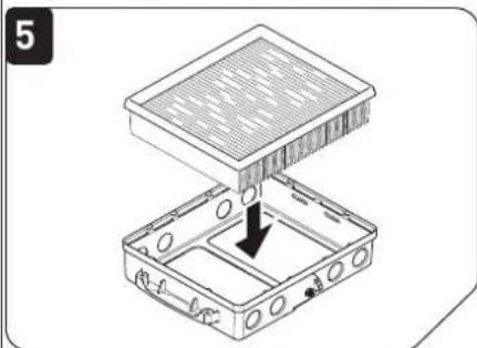
natural_image
Diagram of a mechanical assembly with a grid-like structure and an arrow indicating a force or movement (no text or symbols present)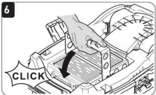
natural_image
Illustration of a mechanical component with a tool inserted, showing internal structure and motion direction (no text or symbols)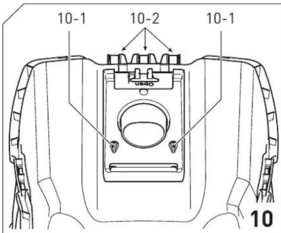
| AbsaugmobilMobile dust extractorsAspirateurs | Seriennummer *Serial number *N° de série *(T-Nr.) |
| CTH 26 E/a | 202403, 202404 |
| CTH 48 E/a | 202405 |
EG-Konformitätserklärung. Wir erklären in alleiniger Verantwortung, dass dieses Produkt allen einschlägigen Bestimmungen der folgenden Richtlinien einschließlich ihrer Änderungen entspricht und mit den folgenden Normen übereinstimmt:
GB EC-Declaration of Conformity. We declare under our sole responsibility that this product is in conformity with all relevant provisions of the following directives including their amendments and complies with the following standards:
CE-Déclaration de conformité communautaire. Nous déclarons sous notre propre responsabilité que ce produit est conforme aux normes ou documents de normalisation suivants:
E CE-Declaración de conformidad. Declaramos bajo nuestra exclusiva responsabilidad que este producto corresponde a las siguientes normas o documentos normalizados:
CE-Dichiarazione di conformità. Dichiariamo sotto la nostra esclusiva responsabilità che il presente prodotto e conforme alle norme e ai documenti normativi seguenti:
NL EG-conformiteitsverklaring. Wij verklaren op eigen verantwoordelijkheid dat dit produkt voldoet aan de volgende normen of normatieve documenten:
⑤ EG-konformitetsförklaring. Vi förklarar i eget ansvar, att denna produkt stämmer överens med följande normer och normativa dokument:
FIN EY-standardinmukaisuusvakuutus. Vakuutamme yksinvastuullisina, etta tuote on seuraavien standardien ja normatiivisten ohjeiden mukainen:
DK EF-konformitetserklæring Vi erklærer at have alene ansvaret for, at dette produkt er i overensstemmelse med de følgende normer eller normative dokumenter:
CE-Konformitetserklæring Vi erklærer på eget ansvar at dette produktet er i overensstemmelse med følgende normer eller normative dokumenter:
Head of Research, Development and Technical Documentation

Ralf Brandt
Head of Standardization & Approbation
natural_image
Technical illustration of a cylindrical mechanical component with threaded ends and directional arrows indicating motion (no text or symbols)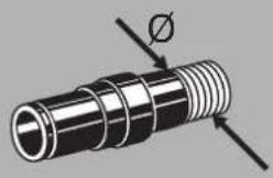
natural_image
Mechanical component diagram showing a threaded shaft with a hole and directional arrows (no text or labels)42 mm 100 27,8
50 mm 141 39,2
Volumenstrom mindestens
[m 3/h]
[l/s]
| CTH 26 E CTH 48 E | ||
| FIS-CTH (3 x) (L, M, H[2]) | 497541 497542 | |
| HF-CT H 498995 498995 | ||
| NF-CT 496169 496169 | ||
1 Safety instructions.... 14
2 Symbols.... 14
3 Technical data.... 15
4 Intended use....16
5 Machine features....16
6 Operation....16
7 Settings....17
8 Working.... 18
9 Service and maintenance.....19
10 Accessories.... 20
11 Environment.... 21
1 Safety instructions
1.1 General safety instructions
WARNING! Read all safety warnings, instructions, illustrations and specifications provided with this tool. Failure to follow all instructions listed below may result in electric shock, fire and/or serious injury.
Save all warnings and instructions for future reference.
- This appliance must not be used by persons (including children) with reduced physical, sensory or mental capabilities, or lack of experience and knowledge. Children need to be supervised to ensure they do not play with the appliance.
- WARNING: This device contains hazardous dust. Only specialists using suitable protective equipment in accordance with these operating instructions may perform emptying and maintenance tasks, including emptying the dust collection container. Never operate the device without the complete filtration system.
- Always use suitable protective equipment!
- If intact following a visual inspection, work in a dry environment according to instructions!
– Risk of explosion and fire: Do not absorb:
- Sparks or hot dust;
- Combustible or explosive materials (e.g. magnesium, aluminium, petrol, diluting agents – with the exception of wood);
- Aggressive materials (e.g. acid, alkaline solutions, solvents);
-
Chemically reactive materials, which lead to the generation of heat, acids/ bases, gases, etc. (e.g. reactive 2-component materials, aluminium and water).
-
Observe all national safety regulations as well as the material manufacturer's specifications!
- Always use the socket on the machine for the purpose specified!
- Do not pull the plug from the socket by the cable.
- Check the plug and the cable regularly and should either become damaged, in order to avoid a hazard, have them replaced by an authorised after-sales service workshop.
- Do not lift or transport using a crane hook or lifting gear!
1.2 Extracting asbestos dust

After the extractor is used to extract asbestos dust in a sealed-off area, it can no longer be used in the white area. Exceptions are only permitted if the asbestos dust extractor has been completely decontaminated by an approved specialist. This must be recorded in writing and signed by the approved specialist.
Fixed filters may only be replaced in suitable areas (e.g. decontamination stations) by an approved specialist.

The applicable national regulations (for example TRGS 519) may contain further provisions that regulate or restrict the application areas of the mobile dust extractor and which must be observed when extracting dust containing asbestos particles.
2 Symbols

Warning of general danger

Risk of electric shock

Read the Operating Instructions/Notes!

Wear a dust mask.

Do not throw in the household waste.
3 Technical data
| Mobile dust extractors | ||
| Power consumption 350 - 1000 W | ||
| Maximum appliance socket connected load EU | CH, DK | 2400 W |
| 1100 W | ||
| GB 240 V/ 110 V | 1800 W/ 500 W | |
| Max. suction capacity (air), turbine [3] | 234 m3/h (3900 l/min) | |
| Max. vacuum, turbine1 | 24000 Pa | |
| Filter surface area 6318 cm2 | ||
| Suction hose D 27 / 32 mm x 3,5 m AS | ||
| Length of the net cable 7,5 m | ||
| Sound pressure level as per EN 60704-2-1 / Uncertainty K 71 dB(A) / 3 dB | ||
| Protection category IP X4 | ||
| Container capacity CTH 26 E/a 26 l | ||
| CTH 48 E/a 48 l | ||
| Dimensions L x W x H CTH 26 E/a 630 x 365 x 540 mm | ||
| CTH 48 E/a 740 x 406 x 1005 mm | ||
| Weight CTH 26 E/a 13,9 kg | ||
CTH 48 E/a 18,8 kg
 | Volume flow at least[m3/h] [l/s] | ||
| 21 mm 25 | 6,9 | ||
| 27 mm/ IAS | 41 | 11,4 | |
| 32 mm 58 | 16,1 | ||
| 36 mm 73 | 20,3 | ||
| 42 mm 100 | 27,8 | ||
| 50 mm 141 | 39,2 | ||
FIS-CTH (3 x) (L, M, H ^[4] )
497541 497542
HF-CT H 498995 498995
NF-CT 496169 496169
4 Intended use
The mobile dust extractor is suitable for the absorption and suction of dust which is hazardous to health with limit values corresponding to dust class 'H' in accordance with EN 60335-2-69, including wood and paint dust.
The mobile dust extractor is suitable for the absorption and suction of dust with carcinogenic and pathogenic particles, as well as asbestos dust.
The mobile dust extractor is designed to absorb water.
The mobile dust extractor is, in accordance with EN 60335-1 and EN 60335-2-69, suitable for increased demands for commercial use.

The user is liable for improper or non-in-tended use.
5 Machine features
The specified illustrations appear at the beginning of the Operating Instructions.
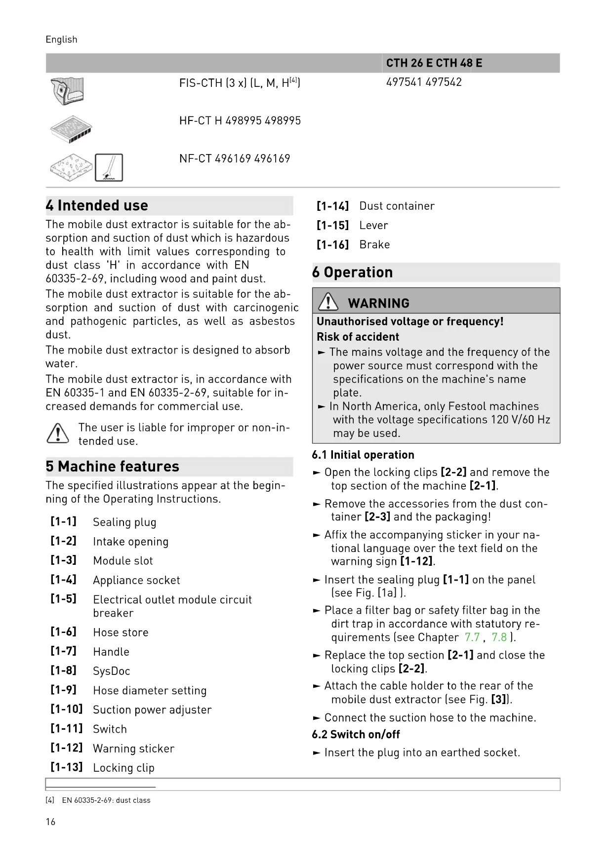
[1-1] Sealing plug
[1-2] Intake opening
[1-3] Module slot
[1-4] Appliance socket
[1-5] Electrical outlet module circuit breaker
[1-6] Hose store
[1-7] Handle
[1-8] SysDoc
[1-9] Hose diameter setting
[1-10] Suction power adjuster
[1-11] Switch
[1-12] Warning sticker
[1-13] Locking clip
[1-14] Dust container
[1-15] Lever
[1-16] Brake
6 Operation

WARNING
Unauthorised voltage or frequency! Risk of accident
The mains voltage and the frequency of the power source must correspond with the specifications on the machine's name plate.
▶ In North America, only Festool machines with the voltage specifications 120 V/60 Hz may be used.
6.1 Initial operation
▶ Open the locking clips [2-2] and remove the top section of the machine [2-1].
▶ Remove the accessories from the dust container [2-3] and the packaging!
- Affix the accompanying sticker in your national language over the text field on the warning sign [1-12].
▶ Insert the sealing plug [1-1] on the panel (see Fig. [1a]).
▶ Place a filter bag or safety filter bag in the dirt trap in accordance with statutory requirements (see Chapter 7.7, 7.8).
▶ Replace the top section [2-1] and close the locking clips [2-2].
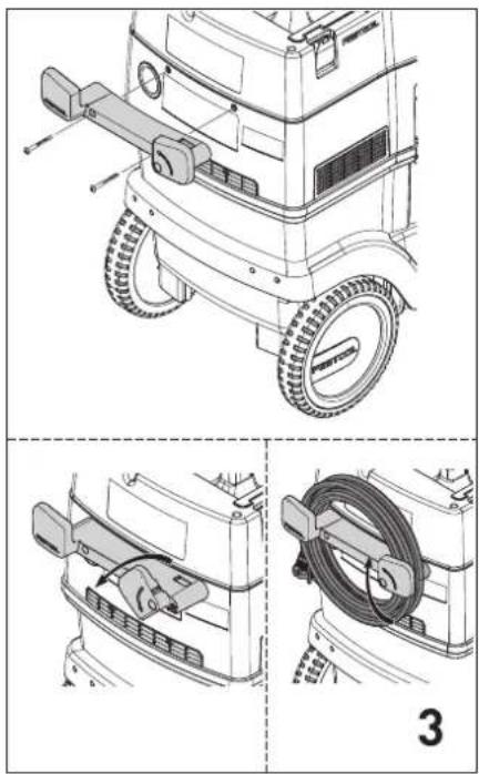
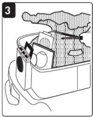
- Attach the cable holder to the rear of the mobile dust extractor (see Fig. [3]).
▶ Connect the suction hose to the machine.
6.2 Switch on/off
▶ Insert the plug into an earthed socket.

WARNING
Risk of injury from tools starting up unexpectedly
Before setting the switch to the "AUTO" or "MAN" position, make sure that the connected tool is switched off.
The switch [1-11] serves as an on/off switch.
Switch position "0"
Appliance socket [1-4] is disconnected from the power, mobile dust extractor is switched off.
"MAN" switch position
Appliance socket [1-4] is connected to the power, the mobile dust extractor starts.
"Auto" switch position
Appliance socket [1-4] is connected to the power, the mobile dust extractor starts when the connected tool is switched on.
7 Settings
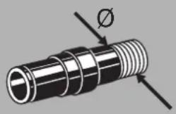
7.1 Adjusting the hose diameter
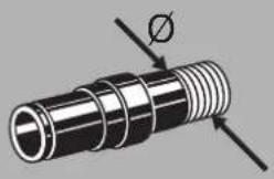
▶ Adjust the hose diameter adjuster [1-9] to match the diameter of the connected hose.

The monitoring devices will measure the air speed in the extractor hose correctly as a result (see chapter Volumetric flow monitoring).
7.2 Connecting electric power tools

WARNING
Risk of injury
▶ Observe the maximum appliance socket connected load (see chapter "Technical data")
▶ Switch off the electric power tool.
- Connect the electric power tool to the appliance socket [1-5].
7.3 Connecting pneumatic tools

WARNING
Risk of injury
▶ Switch off the air tool.
If the compressed air module [1-3] (496141) is installed, the automatic switch-on function of the mobile dust extractor also works in combination with pneumatic tools.
We also recommend installing the VE service unit (495886). The service unit filters and lubri-
cates the compressed air and enables an adjustment of the air pressure. An IAS adapter (454757) is available to connect Festool pneumatic tools to the IAS system.
The operating pressure of the tool must be 6 bar for the automatic switch-on unit to function correctly.
7.4 Adjusting the suction power
▶ Use the rotary knob.
7.5 Applying the brake
Folding out the black brake lever [1-15] prevents the mobile dust extractor from rolling. To achieve this, lift the front end of the mobile dust extractor slightly and push the black brake lever downwards until it latches into place. Push the green lever again to release.
7.6 Temperature cut-out
A temperature cut-out switches the mobile dust extractor off when it reaches a critical temperature to prevent overheating.
- A temperature cut-out switches the mobile dust extractor off when it reaches a critical temperature to prevent overheating. - Switch off the mobile dust extractor, allow to cool for about 5 minutes then switch on again.

Not possible to switch on: contact Festool service workshop.
7.7 Changing the filter bag (SC-FIS-CT26/48)
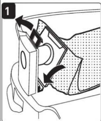
Removing the filter bag [4]
▶ Open the locking clips [2-2] and remove the top section of the machine[2-1].
▶ Remove the filter bag.
▶ Dispose of the used filter bag in accordance with statutory regulations.
▶ Clean the dust container [2-3].
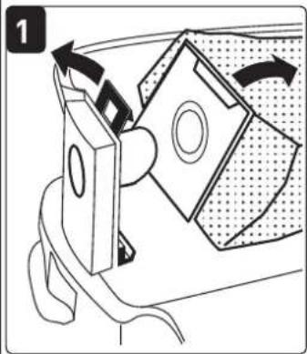
Inserting the filter bag [5]
▶ Insert a new filter bag (SC-FIS-CT26/48) in the inlet port of the dust container and interlock it. Important: be aware that the locking engages.
![FESTOOL CTH 26L H Class - Inserting the filter bag [5] - 1](/content/2026/03/535986/images/f7c6476c7e676a9b2fca4aed093f9035294ba9685801ceee129b5acf9a51de42.jpg)
Make sure that the filter bag is not pinched between the top and bottom sections.
▶ Replace the top section [2-1] and close the locking clips [2-2].
7.8 Changing the safety filter bag (FIS-CTH 26/48)

Always use the safety filter bag for absorbing Class H dust.
Removing the safety filter bag [6]
▶ Close off the extractor opening [1-2] using the sealing plug [1-1].
▶ Open the locking clips [2-2] and remove the top section of the machine[2-1].
▶ Knock the material of the plastic bag upwards and close the lateral openings with the adhesive tabs.
- Close the plastic bag around the filter bag using the cable ties supplied.
▶ Remove the safety filter bag
▶ Dispose of the used safety filter bag in accordance with statutory regulations.
▶ Clean the dust container [2-3].
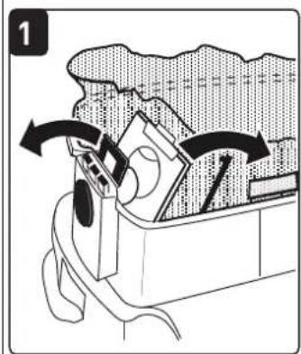
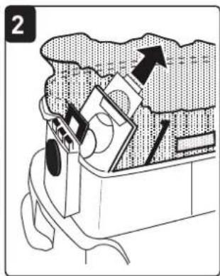
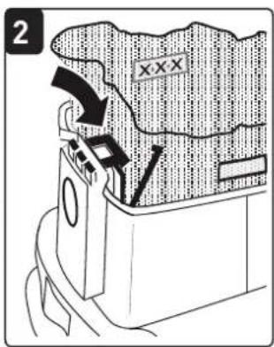
Inserting the safety filter bag [7]
▶ Insert a new safety filter bag (FIS-CTH 26/48) on the inlet nozzle of the container and lock in position. Important: Ensure the lock is snapped in.
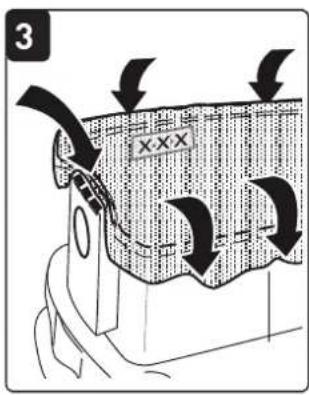
- Place the plastic bag over the edge of the container. The lateral openings on the safety filter bag must be positioned inside the dirt trap.
![FESTOOL CTH 26L H Class - Inserting the safety filter bag [7] - 1](/content/2026/03/535986/images/92d3c47433a91c3522ec8ba51ab8dc34bf6e66a9eabf48c7b25a75bf3f23ff12.jpg)
Ensure the contacts are [10-2]free.
![FESTOOL CTH 26L H Class - Inserting the safety filter bag [7] - 2](/content/2026/03/535986/images/b87a1d398ac779b73a1ed5554d9731cd6764be8a609f7227989411d8e6cab94c.jpg)
Make sure that the filter bag is not pinched between the top and bottom sections.
- Replace the top section [2-1] and close the locking clips [2-2].
7.9 Volumetric flow monitoring
An acoustic warning signal sounds if the air speed in the suction hose falls below 20 m/s.
| Possible causes Solution | |
| Value set on the suction power adjust-er [1-9] is too low. | Set the suction power adjuster to a higher value (see Chapter 7.4). |
| Rotary knob [1-8] not set to the correct hose diameter. | Set the knob to the correct hose diameter (see Chap-ter 7.1). |
| Suction hose blocked or kinked. Remove blockage or kink. | |
| Filter bag full. Insert a new filter bag (see Chapter 7.7). | |
| Dirty main filter. Changing the main filter (see Chapter 9.1). | |
| Monitoring electronics malfunction. Send to a Festool service workshop for repair. | |
| Wet extraction. Functional reliability not affected, no actions required. | |
8 Working
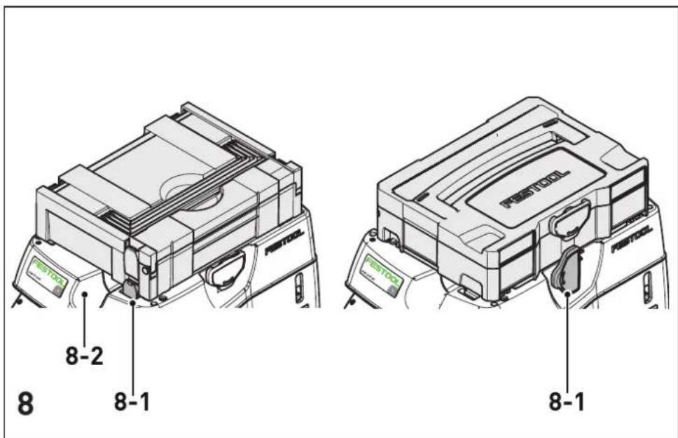
8.1 Handling
Hose store: after finishing work, you can feed the suction hose through the recess [8-2] and place it in the hose store.
SysDoc Systainer attachment system: a Systainer can be attached to the storage area via the four slides ore the T-Loc [8-1].
8.2 Extracting dry materials
| Hazardous dustDamage to the respiratory passage► Always use a safety filter bag and an appropriate main filter when extracting hazardous materials.► Do not use the machine if the volumetric flow monitoring function is inactive. |
When extracting large quantities of oak or beech wood dust or dust that exceeds the permitted limit values, only extract from a single machine (electric or air tool).
Observe the following when extracting dust generated by operating electric power tools:
If the exhaust air is discharged back into the room, the air renewal rate L within the room must be sufficient. The volume of air discharged back into the room must not exceed 50% of the fresh air volume flow (room volume V_R x air renewal rate L_w ). Observe all the relevant regional regulations.
Remember: A moist main filter clogs more quickly when extracting dry materials. Therefore, dry the main filter before extracting dust or replace the damp filter with a dry one.
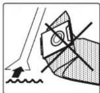
8.3 Extracting fluids

WARNING
Hazardous dust
Damage to the respiratory passage
▶ Hazardous dust must never be taken in during wet extraction.
Before the absorption of liquids remove the filter bag or safety filter bag (see Chapter 7.7, 7.8). The use of a special wet filter is recommended.
The dust extractor stops automatically when the maximum level is reached.

CAUTION
Escaping foam and fluids
▶ Switch off the machine immediately and empty the dirt trap.
8.4 The antistatic system
Friction inside the extraction hose causes static electricity to develop during extraction. Operating personnel may receive unpleasant electric shocks while working. The mobile dust extractor is fitted with an antistatic system as standard to discharge any static electricity that may develop. However, always use the enclosed antistatic extraction hose.
8.5 After finishing work

Pull the plug from the socket when the machine is not in use and prior to maintenance and cleaning work.
▶ Switch off the mobile dust extractor and pull out the mains plug.
▶ Wind up the mains power cable.
▶ Empty the dirt trap.
▶ Close off the extractor opening [1-2] using the sealing plug [1-1].


WARNING
Hazardous dust
Damage to the respiratory passage
- Wipe down the mobile dust extractor and clean all accessories thoroughly using the extractor (inside and out) before removing from the working area.
▶ Parts that you were not able to clean thoroughly must be sealed in an airtight plastic bag prior to transportation.
▶ Wear a dust mask!

The machine shall be stored indoors only.
▶ Place the mobile dust extractor in a dry room inaccessible to unauthorised users.
Observe for dust reduced transport:
▶ Observe for dust reduced transport:
▶ Ensure a secure fixation during transport.

Only transport the appliance with closed sealing plug.
9 Service and maintenance


WARNING
Risk of injury, electric shock
▶ Always disconnect the mains plug from the socket before performing maintenance work on the machine!
▶ All maintenance and repair work which requires the motor housing to be opened must only be carried out by an authorised service workshop.

Customer service and repair only through manufacturer or service workshops: Please find the nearest address at: www.festool.com/service
Use only original Festool spare parts! Order No. at: www.festool.com/service
Damaged safety devices and components must be repaired or replaced in a recognised special-
English
ist workshop, unless otherwise indicated in the operating manual.
Observe the following instructions:
- The manufacturer or an instructed person must perform a dust test at least once a year to determine whether the filter is damaged, the machine is sealed properly and the monitoring features are functioning correctly.
- In addition the machine filtration efficiency should be tested at least annually, or more frequently as may be specified by national requirements. The test method can be used to verify the machine's filter efficiency are specified in EN 60335-2-69 AA.22.201.2.. If the test fails, it shall be repeated with a new essential filter.
- Anything that cannot be cleaned must be discarded in impermeable bags. Observe applicable disposal regulations!
- For user servicing, the machine must be dismantled, cleaned and serviced, as far as is reasonably practicable, without causing risk to the maintenance staff and others. Suitable precautions include, decontamination before dismantling, provision from local filtered exhaust ventilation where the machine is dismantled, cleaning of the maintenance area and suitable personal protection.

Information for sending dust extractors to repair workshops
Observe the following instructions, which are designed to protect personnel in repair workshops and during transportation:
- Clean the machine thoroughly (inside and out).
▶ Remove the filter/disposal bag. - Pack the machine in suitable airtight plastic bag.
▶ Attach a list of the hazardous substances that the machine has extracted on the outside of the airtight packaging.
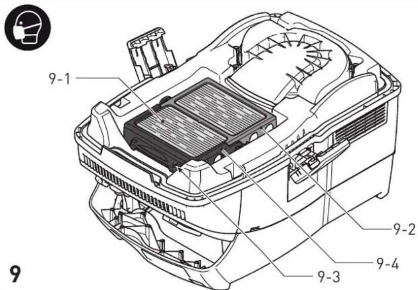
9.1 Changing the filter element


WARNING
Dust raised during changing filter bag and main filter
▶ Wear a dust mask!
▶ If you are disposing of asbestos, wear disposable clothing.

WARNING
Risk of injury
▶ Do not reuse the essential filter element after removal out of the machine.
NOTE
Motor damage
▶ Never operate the extractor without a filter element fitted as the motor may become damaged.
▶ Open the locking clips [2-2] and remove the top section of the machine [2-1].
▶ Turn the top section of the machine so that the main filter [9-1] is facing upwards (Fig. [9]).
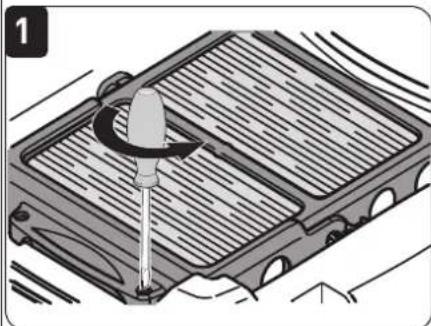
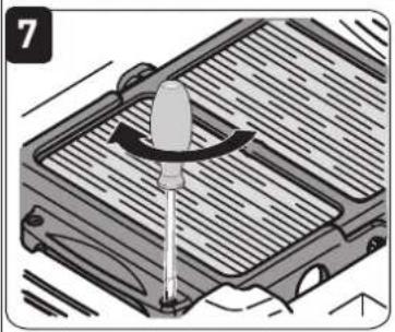
- Remove the two safety bolts [9-3] on the lever [9-4] using a screwdriver.
▶ Fold over the lever [9-4] and remove the retainer [9-2] with the main filter.
- Insert the retainer with the main filter in the safety bag supplied.
▶ Remove the main filter from the retainer.
▶ Remove the retainer from the safety bag.
▶ Close and dispose of the safety bag in accordance with statutory regulations.
▶ Clean any dust deposits from the area behind the main filter.
▶ Insert a new main filter in the frame.
- Insert the retainer [9-2] with the main filter and fold over the lever [9-4] until it engages in position.
▶ Tighten the safety screws[9-3].
▶ Replace the top section [2-1] and close the locking clips [2-2].
9.2 Emptying the dust container
The dust container [2-3] can be emptied once the top section has been removed.
▶ After extracting fluids, clean the fill level sensors [10-1] regularly with a soft cloth and inspect for damage.
10 Accessories
The order numbers for the accessories and filters can be found in the Festool catalogue or on the Internet at "www.festool.com".
10.1 Modules
The following modules for upgrading the mobile dust extractor are available in the accessories programme. Modules must be fitted to the
module slot [1-3] by an authorised service workshop:
- Compressed air module,
- Socket module with permanent power supply,
- Socket module with automatic switch-on unit (not suitable for GB 110 V version),
- Energy box module (EAA) for using the automatic switch-on unit on the EAA.
You can find more detailed information on the modules at "www.festool.com".
11 Environment

Do not dispose of the tool in the household waste! Recycle tools, accessories and packaging. Observe applicable national regulations.
EU only: In accordance with European Directive 2002/96/EC on waste electrical and electronic equipment and implementation in national law, used power tools must be collected separately and handed in for environmentally friendly recycling.
Information on REACH: www.festool.com/reach
Sommaire
natural_image
Mechanical component diagram showing a threaded shaft with a flanged end and a central hole (no text or symbols)21 mm 25
6,9
27 mm/ IAS
Débit au minimum
[m ³/h]
[l/s]
41
11,4
natural_image
Mechanical component diagram showing a threaded shaft with two arrows indicating direction (no text or symbols)32 mm 58 16,1
36 mm 73 20,3
42 mm 100 27,8
50 mm 141 39,2
Débit au minimum
[m ^3 /h] [l/s]
CTH 26 E CTH 48 E

FIS-CTH (3 x) (L, M, H ^[6] ) 497541 497542
HF-CT H 498995 498995
NF-CT 496169 496169
natural_image
Technical illustration of a cylindrical mechanical component with threaded sections and an angular symbol (no text or labels)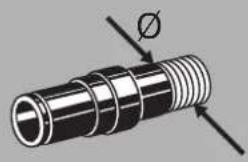
natural_image
Mechanical component diagram showing a threaded shaft with flanged end and central bore (no text or symbols)42 mm 100 27,8
50 mm 141 39,2
Volumestroom minstens
[m 3/h]
[L/s]
CTH 26 E CTH 48 E

FIS-CTH (3 x) (L, M, H[12])
497541 497542
HF-CT H 498995 498995
NF-CT 496169 496169
[1-2] Aanzuigopening
[1-3] Moduleslot
[1-4] Toestelcontactdoos
[1-5] Slangdepot
[1-6] Handgreep
[1-7] SysDoc
[1-8] Instelling slang diameter
[1-9] Zuigkrachtregeling
[1-10] Apparaatschakelaar
natural_image
Mechanical component diagram showing a cylindrical shaft with threaded end and two directional arrows indicating motion (no text or symbols)Luftmængde mindst
[m 3/h]
[l/s]
21 mm 25 6,9
27 mm/ IAS 41 11,4
32 mm 58 16,1
36 mm 73 20,3
42 mm 100 27,8
50 mm 141 39,2
FIS-CTH (3 x) (L, M, H ^[18] )
497541 497542

HF-CT H 498995 498995
NF-CT 496169 496169
[1-10] Apparatbryter
[1-11] Varselskilt klistremerke
[1-12] Låseklemme
[1-13] Smussbeholder
[1-15] Brems
6 Igangsetting

ADVARSEL
Sette inn filterpose [5]
- Sett i en ny filterpose (SC-FIS-CT26/48) (bilde [4]). Viktig: Trykk filterposemuffen kraftig på åpningen.
![FESTOOL CTH 26L H Class - Sette inn filterpose [5] - 1](/content/2026/03/535986/images/956420263d1b4feb9f72cd80d018ee46bc951da2ac1413ad506138cdc773c52a.jpg)
natural_image
Technical illustration of a cylindrical mechanical component with threaded end and flange, showing internal threading (no text or symbols)| 21 mm 25 6,9 | ||
| 27 mm/ IAS | 41 11,4 | |
| 32 mm 58 16,1 | ||
| 36 mm 73 20,3 | ||
| 42 mm 100 | 27,8 | |
| 50 mm 141 | 39,2 |
![FESTOOL CTH 26L H Class - Sette inn filterpose [5] - 2](/content/2026/03/535986/images/31886a83e14086f2012d0063c686d0c887e2f69ff1cc95ef2b15394da4975ea9.jpg)
FIS-CTH (3 x) (L, M, H ^[26] )
497541 497542
![FESTOOL CTH 26L H Class - Sette inn filterpose [5] - 3](/content/2026/03/535986/images/eac49fec77f567a8be74b76794dd6ce6a6d165e2394f742e5bd9b41f92892f02.jpg)
HF-CT H 498995 498995
![FESTOOL CTH 26L H Class - Sette inn filterpose [5] - 4](/content/2026/03/535986/images/ca59b10763b180c1eecbd2da2b060fb5ec26caa98d8ad9c8577e6fa24dd95446.jpg)
NF-CT 496169 496169