
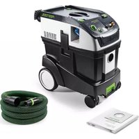
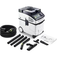
Cleantec CTL 36 AC PLANEX - Vacuum Cleaner FESTOOL - Free user manual and instructions
Find the device manual for free Cleantec CTL 36 AC PLANEX FESTOOL in PDF.

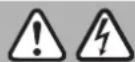
| Product type | Mobile vacuum cleaner |
| Brand | Festool |
| Model | Cleantec CTL 36 AC PLANEX |
| Dimensions (L x W x H) | 587 x 372 x 606 mm |
| Weight | 15.1 kg |
| Tank volume | 36 l |
| Power consumption | 350 - 1200 W |
| Max. connection value (EU) | 2400 W |
| Max. volume flow | 130 m³/h (vacuum) / 234 m³/h (central) |
| Max. vacuum pressure | 240 hPa |
| Power cable length | 7.5 m |
| Sound pressure level | 71 dB(A) (uncertainty 3 dB) |
| Hand-arm vibration | < 2.5 m/s² |
| Protection rating | IP X4 |
| Dust category | L (low hazard, limit value > 1 mg/m³) |
| Main functions | Dry and wet dust extraction, AUTO-CLEAN, power regulation, wired/wireless tool connection, Bluetooth remote control |
| Maintenance and cleaning | Automatic filter cleaning (ACTIVATION via AC button), manual cleaning, regular check of sensors and filter |
| Safety | Thermal fuse, automatic shutdown in case of foam/liquid leakage, parking brake, continuous monitoring required |
| Spare parts and repairability | Original Festool spare parts, repairs by authorized workshop, order reference on www.festool.com |
| General information | Integrated Bluetooth®, tool data chip, compatible with Festool App, SYS-Dock for Systainer |
Frequently Asked Questions - Cleantec CTL 36 AC PLANEX FESTOOL
User questions about Cleantec CTL 36 AC PLANEX FESTOOL
0 question about this device. Answer the ones you know or ask your own.
Ask a new question about this device
Download the instructions for your Vacuum Cleaner in PDF format for free! Find your manual Cleantec CTL 36 AC PLANEX - FESTOOL and take your electronic device back in hand. On this page are published all the documents necessary for the use of your device. Cleantec CTL 36 AC PLANEX by FESTOOL.
USER MANUAL Cleantec CTL 36 AC PLANEX FESTOOL
natural_image
Row of industrial vacuum cleaner machines with green and black buttons, no visible text or symbols1
6
8
natural_image
Line drawing of a small wheeled vehicle with wheels and a handle (no text or symbols)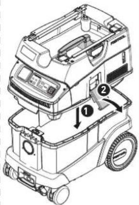
natural_image
Technical line drawing of a vehicle rear view showing front, side, and side views with no visible text or symbols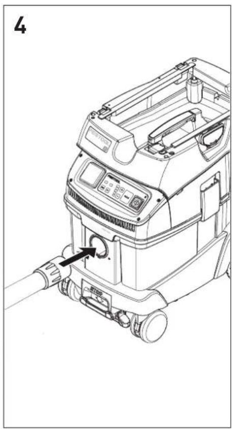
natural_image
Line drawing of a mechanical device with a hand operating a valve (no text or symbols present)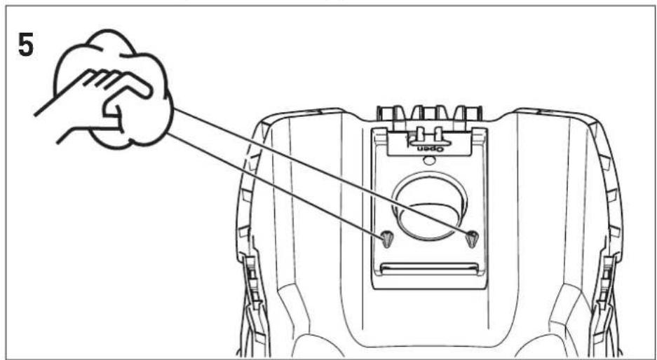
natural_image
Diagram of a mechanical component with two upward arrows indicating motion or force, no text or symbols present
natural_image
Mechanical assembly diagram showing a clamping mechanism with no visible text or symbols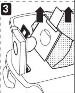
natural_image
Diagram of a mechanical device with directional arrows indicating movement or force (no text or symbols present)
natural_image
Diagram of a mechanical component with downward arrows indicating force or movement (no text or symbols)
SC FIS-CT26
SC FIS-CT36
SC FIS-CT48
natural_image
Diagram of a mechanical component with directional arrows indicating movement (no text or symbols)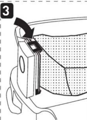
natural_image
Diagram of a mechanical component with a directional arrow indicating movement, no text or symbols present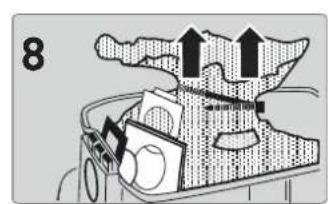

natural_image
Diagram of a mechanical device with gears and components, no visible text or symbols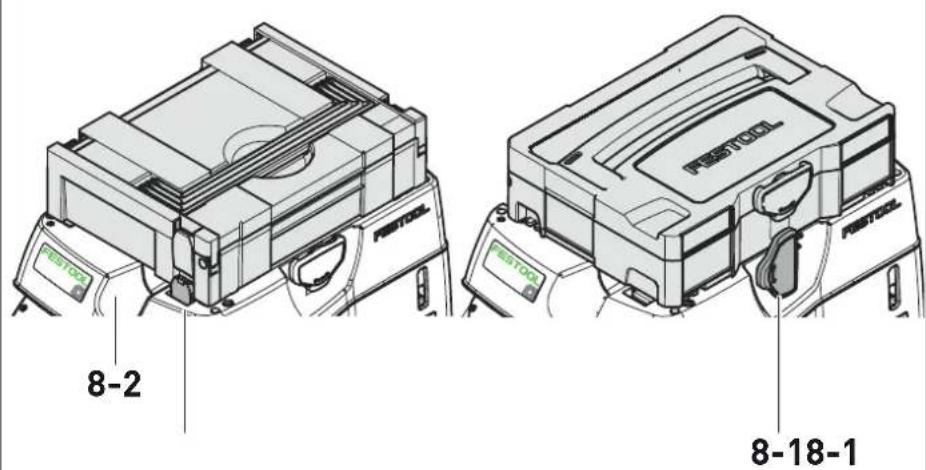

ENS-CT26
ENS-CT36
ENS-CT48
natural_image
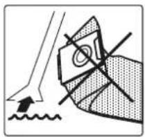
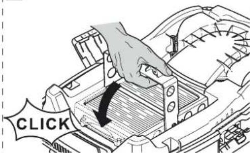
Diagram showing a hand holding a triangular object with crosshair and shaded area, no text or symbols present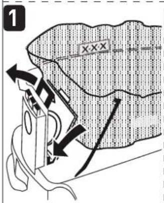
10
natural_image
Technical line drawing of an internal appliance with visible internal components and a hand pointing to a detail (no text or symbols)
CT
HF-CT 26/36/48
CT AC
HF-CT 26/36/48 HP
1
natural_image
Diagram of a hand pressing down on a mechanical component with arrows indicating motion (no text or symbols)2
natural_image
Illustration of hands assembling a mechanical component with a bag nearby (no text or symbols)3
natural_image
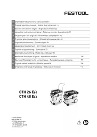
Technical line drawing of a mechanical assembly with a grid-like structure and an arrow indicating a downward motion (no text or symbols present)4
en: EU Declaration of Conformity. We declare under sole responsibility that this product complies with all the relevant requirements in the following EU Directives, and following standards or normative documents were applied:
S.I. 2008/1597 Supply of Machinery [Safety] Regulations 2008
S.I. 2017/1206 Radio Equipment Regulations 2017
S.I. 2016/1091 Electromagnetic Compatibility Regulations 2016
S.I. 2021/422 Restriction of the Use of Certain Hazardous Substances in Electrical and Electronic Equipment Regulations 2012
BS EN 60335-1:2012 + AC:2014 + A11:2014 + A13:2017 + A15:2021,
BS EN 60335-2-69:2012,
BS EN 300 328 V2.2.2,
BS EN 301 489-1 V.1.9.2,
BS EN 301 489-17 V3.2.4,
BS EN 303 446-1 V1.2.1,
BS EN 55032:2015 + A11:2020,
BS EN 55014-1:2017 + A11:2020,
BS EN 55014-2:1997 + A1:2001 + A2:2008 + AC:1997,
BS EN 61000-3-2:2014,
BS EN 61000-3-3:2013,
BS EN 62233:2008 + AC:2008,
BS EN 62311:2008,
BS EN IEC 63000:2018
Head of Research & Development Products

Tim Weber
Head of Product Compliance
Inhaltsverzeichnis
1 Safety warnings....18
2 Symbols....19
3 Parts of the machine....19
4 Technical data.... 20
5 Intended use....21
6 Commissioning....21
7 Connecting a device.... 21
8 Settings....22
9 Working.... 23
10 Service and maintenance....24
11 Accessories.... 24
12 Environment....24
13 General information....24
1 Safety warnings


WARNING! Read all safety warnings and instructions. Failure to follow the safety warnings and instructions may result in electric shock, fire and/or serious injury.
Save all safety warnings and instructions for future reference.
- This machine is not intended for use by persons (including children) with reduced physical, sensory or mental capabilities, or lack of experience and knowledge. Children should be supervised to ensure that they do not play with the appliance.
- This machine must not be used by people who might have a particularly adverse reaction to an electric shock (e.g. people with cardiac pacemakers), because the possibility of the machine building up a static charge cannot be excluded.
- Ensure you are on a firm base. The effects of a shock moment, e.g. due to antistatic discharge, may lead to accidents.
- This machine must only be operated under constant supervision. To prevent potential hazards, never let it run unsupervised.
- WARNING Operators shall be adequately instructed on the use of these machines.

- WARNING The machine may contain hazardous dust. Only have the machine maintained and emptied, and only have the filter replaced by an authorised specialist using suitable protective equipment.
- Always operate with the filter system installed!
- Always use suitable protective equipment!
- If intact following a visual inspection, work in a dry environment according to instructions!
-
Risk of explosion and fire! Do not extract:
-
Sparks, glowing particles or hot dust;
- combustible or explosive materials (e.g. magnesium, aluminium, petrol, diluting agents);
- aggressive materials (e.g. acid, alkaline solutions, solvents);
- chemically reactive materials which lead to the generation of heat, acids/bases, gases, etc. (e.g. reactive two-component materials, aluminium and water).
- Observe all national safety regulations as well as the material manufacturer's specifications!
- WARNING Only use the socket outlet on the machine for purposes specified in the instructions.
- Check the plug, the electrical outlet module, the cable and the filter regularly in order to prevent a hazard. Damaged electrical components must be replaced by an authorised service workshop only.
- The mains plug must always be disconnected from the socket before performing cleaning or maintenance tasks, when replacing consumables or when converting the machine.
- CAUTION Clean the water level limiting device regularly and examine it for signs of damage.
- WARNING If foam or liquid escapes from the machine, switch off immediately.
- Use only the original Festool suction hose.
- Pay attention to the work environment and watch out for your own safety and the safety of others when transporting or working with the machine.
In this way, you can for example prevent tripping hazards caused by the suction hose or mains cable.
- Only carry the machine using the handle provided.
- Do not lift or transport using a crane hook or lifting gear.
- Keep packaging film away from children.
There is a risk of suffocation.
2 Symbols

Warning of general danger

Warning of electric shock

Read the operating manual and safety warnings.

Wear a dust mask.

Tip or advice

Handling instruction

WARNING! The machine may contain hazardous dust!

Dust class L (low risk) suitable for separation of dust with an exposure limit value greater than 1 mg/m^3

Do not dispose of it with domestic waste.

CE conformity marking

UKCA marking: Confirms the conformity of the product with UK regulations.

Machine contains a chip which stores data. See section 13.3
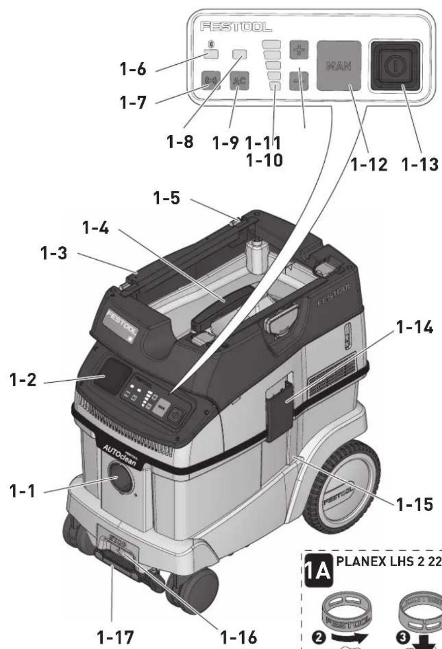
3 Parts of the machine
[1-1] Intake opening
[1-2] Electrical outlet module
[1-3] Hose holder
English
| [1-4] | Handle | [1-12] | MAN button |
| [1-5] | SYS dock | [1-13] | Switch |
| [1-6] | Connection display | [1-14] | Locking clip |
| [1-7] | Connection button | [1-15] | Dirt trap |
| [1-8] | AC indicator (variants with AUTOCLEAN only) | [1-16] | Release button (brake) |
| [1-17] | Brake | ||
| [1-9] | AC button (variants with AUTOCLEAN only) | The specified illustrations appear at the beginning of the operating manual. | |
| [1-10] | Suction power adjustment status indicator | Accessories shown or described are not always included in the scope of delivery. | |
| [1-11] | Buttons for suction power adjustment | ||
4 Technical data
| Mobile dust extractors CT 26-48 EI | ||
| CT 26-48 EI AC | ||
| Power consumption 350 - 1200 W | ||
| Max. electrical outlet module connected load EU | CH, DK | 2400 W |
| 1100 W | ||
| GB 230 V/110 V | 1800 W/ 230 W | |
| KR | 2300 W | |
| Max. volume flow (air), extractor/turbine 130 m3/h / 234 m3/h | ||
| Max. vacuum, turbine 240 hPa | ||
| Suction hose (depending on mobile dust extractor version) D27/32x3.5m-AS/CTR | ||
| D36x3.5-AS/KS/B/LHS 225 | ||
| D36/32x3.5m-AS/R | ||
| Mains power cable length 7,5 m | ||
| Sound pressure level as per EN 60335-2-69/uncertainty K 71 dB(A)/ 3 dB | ||
| Hand-arm vibrations in accordance with EN 60335-2-69 < 2,5 m/s2 | ||
| Protection class IP X4 | ||
| Frequency 2402 Mhz - 2480 Mhz | ||
| Effective isotropic radiated power (EIRP) < 10 dBm | ||
| Container capacity CT 26 26 l | ||
| CT 36 36 l | ||
| CT 48 48 l | ||
| Dimensions L x W x H CT 26 | 587 x 372 x 539 mm | |
| CT 36 | 587 x 372 x 606 mm | |
| CT 48 | 593 x 405 x 687 mm | |
| Weight | CT 26 | 14,6 kg |
| CT 36 | 15,1 kg | |
| CT 48 | 17,0 kg | |
5 Intended use
Mobile dust extractor suitable for
- extracting dust up to 1mg / m^3 according to dust class L,
- extracting water,
- for increased loads during commercial use, according to IEC/EN 60335-2-69.

The user is liable for improper or non-in-tended use.
6 Commissioning

WARNING
Unauthorised voltage or frequency!
Risk of accidents
▶ Observe the specifications on the machine's name plate.
▶ Observe country-specific regulations.
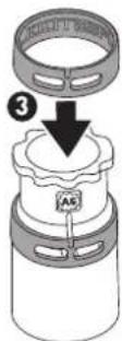
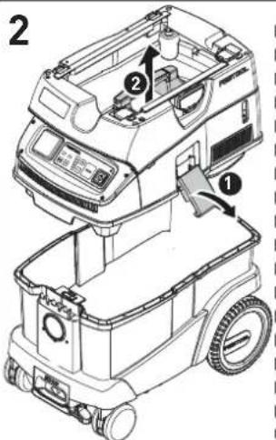
6.1 Initial commissioning
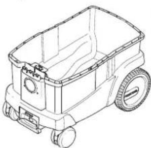
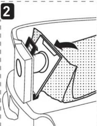
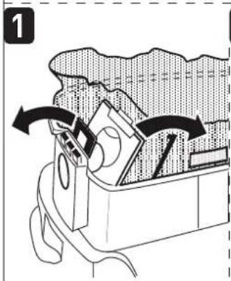
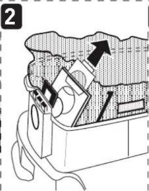
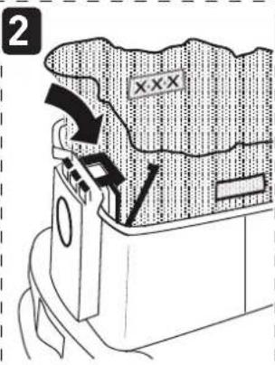
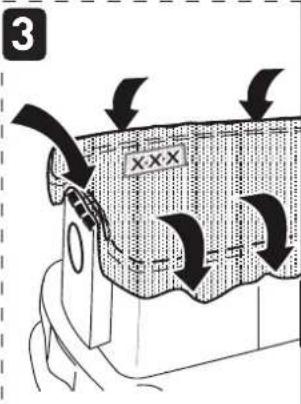
▶ Insert the filter/disposal bag [2].
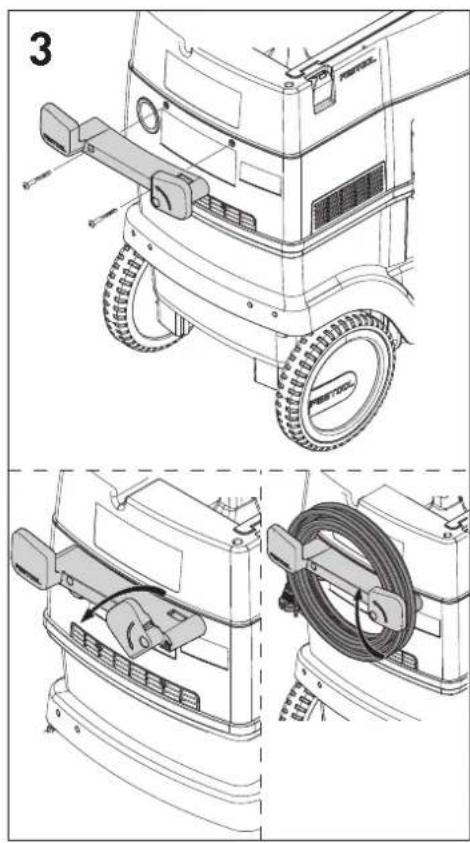
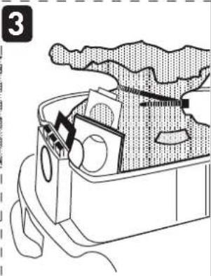
▶ Fit the cord holder [3].
▶ Connect the suction hose [4].
6.2 Connecting a mobile dust extractor

WARNING
Risk of injury from power tools starting up unexpectedly
▶ Before switching on, ensure that the connected power tool is switched off.
WARNING
Risk of injury from electric current
- Insert the mains plug into an earthed mains socket.
▶ Do not reach into the electrical outlet module on the mobile dust extractor.
While the mobile dust extractor is connected to the mains socket, an electric current is running through electrical outlet module on the mobile dust extractor at all times.
Connecting the mobile dust extractor to a mains socket
The mobile dust extractor is switched off.
▶ Connect the power cable to a mains socket.
☑ The electrical outlet module [1-2] is live.
Switching the mobile dust extractor to standby mode
▶ Press the on/off switch [1-13].
☑ The electrical outlet module [1-2] is live.
i The green LED [1-10] indicates standby mode.
Starting the mobile dust extractor automatically
The mobile dust extractor is in standby mode.
▶ To start the mobile dust extractor automatically: Switch on the connected power tool.
Starting the mobile dust extractor manually
The mobile dust extractor is in standby mode.
▶ Press the MAN button [1-12].

Pull the mains plug from the mains socket when you are not using the mobile dust extractor and before perform-
ing any cleaning and maintenance work.
7 Connecting a device

WARNING
Risk of injury from the mobile dust extractor starting up unexpectedly
▶ Before performing any work with the mobile dust extractor, check which remote control and which power tool are connected to the mobile dust extractor.
▶ The remote control must only be attached to the suction hose.
▶ A battery-powered power tool must always be connected to the mobile dust extractor via the suction hose. After finishing work, the connection to the mobile dust extractor must be disconnected.
7.1 Connecting a power tool

WARNING
Risk of injury
▶ Observe the maximum electrical outlet module connected load (see "Technical data" section).
▶ Switch off the power tool.
Connecting a mains-powered power tool to the mobile dust extractor
- Connect the power tool to the electrical outlet module [1-2].
☑ The power tool is connected to the mobile dust extractor via the power cable.
Connecting a battery-powered power tool to the mobile dust extractor
▶ In standby mode, press the connection button [1-7].
English
The connection display [1-6] flashes slowly. For a period of 60 seconds, the mobile dust extractor is ready for connection.
▶ Turn on the battery-powered power tool.
The mobile dust extractor starts up and the battery-powered power tool is connected until the mobile dust extractor is manually switched off or the mains plug is disconnected. The cordless tool must then be connected again.
Connecting a new battery-powered power tool overwrites the previous connection.
7.2 Connecting the CT-F I remote control
Connecting the remote control and the mobile dust extractor
To be able to connect a remote control to a mobile dust extractor, the remote control must be reset (see "Resetting the remote control"). A remote control that has not been connected previously can be connected directly.
A connection that has been established between the remote control and the mobile dust extractor will persist even after the mobile dust extractor has been manually switched off or the mains plug has been disconnected.
▶ Hold down the connection button [1-7] on the mobile dust extractor for three seconds in standby mode.
The connection display [1-6] flashes rapidly.
For a period of 60 seconds, the mobile dust extractor is ready for connection.
▶ Press the MAN button on the remote control.
The remote control is permanently stored in the mobile dust extractor.
Switching on/off
Once the remote control is connected to the mobile dust extractor, the mobile dust extractor can be switched on and off with the remote control.
▶ Press the MAN button on the remote control to switch the device on and off.
Resetting on the remote control
Resetting deletes the connection between a remote control and the mobile dust extractor.
▶ Hold down the connection button and the MAN button for ten seconds.
☑ The LED indicator lights up purple if the reset has taken place.
7.3 Festool app\*
The mobile dust extractor can be configured with the Festool app.
▶ Hold down the connection button [1-7] on the mobile dust extractor for three seconds in standby mode.
The connection display [1-6] flashes rapidly.
For a period of 60 seconds, the mobile dust extractor is ready for connection.
▶ Follow the instructions provided in the Festool app.
* Not available in all countries.
8 Settings
8.1 Adjusting the suction power
▶ Press the plus or minus button [1-11] while extracting.
8.2 Connecting sleeve
The bypass function of the connecting sleeve prevents strong suction from sanding machines and floor nozzles on smooth surfaces.
Open
▶ Turn the adjusting ring to the "OPEN" position.
Close
▶ Turn the adjusting ring to the "CLOSE" position.
8.3 Applying the brake
Folding out the black brake lever [1-17] prevents the mobile dust extractor from rolling. To achieve this, lift the front end of the mobile dust extractor slightly and push the black brake lever downwards until it latches into place. Press the release button [1-16] to release it.
8.4 Temperature cut-out
A temperature cut-out switches the mobile dust extractor off when it reaches a critical temperature to prevent overheating. The bottom LED indicates a fault.
LED lights up red Excessive temperature
▶ Switch off the mobile dust extractor, let it cool down.
▶ Switch on the mobile dust extractor again after approx. five minutes.
9 Working
9.1 Handling
Hose holder: After finishing work, you can feed the suction hose through the opening [8-2] and place it in the hose holder.
SYS-Dock Systainer storage area: A Systainer can be fastened to the storage area with the four slides or the T-Loc lock [8-1].
9.2 AUTOCLEAN – cleaning the main filter (variants with AUTOCLEAN only)

Only in conjunction with a disposable bag (to comply with dust class "L"). Not
for use during wet extraction.
Switching automatic cleaning on and off
▶ In standby mode, press the AC button [1-9] to switch AUTOCLEAN on or off.
The AC function can be configured using the Festool App*.
Manual cleaning
▶ Press the AC button [1-9] while extracting.
Full manual cleaning
▶ While extracting, cover the end of the nozzle or suction hose with your hand or CT-VS closing slide for three seconds.
▶ Press and hold the AC button [1-9] for at least three seconds.
Do not clean the main filter too often within a short period of time.
Within 1 minute maximum:
1x full manual dedusting
3x manual dedusting
* Not available in all countries.
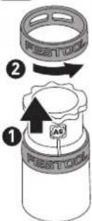
9.3 Special features of the CTL 36 E AC-LHS
To use the mobile dust extractor in combination with the PLANEX:
▶ Use kink-resistant suction hose D 36 mm x 3.5 m-AS.
▶ Use a special suction sleeve for connecting the PLANEX.
▶ Use closing slide CT-VS between the intake opening [1-1] and suction hose.
▶ Attach the tool holder.
▶ Always use with a disposal bag!
Bypass function
In tasks that require a low extraction setting (e.g. on soft surfaces).
▶ Activate bypass function on special extraction sleeve [1A].
9.4 Extracting dry materials

CAUTION
Hazardous dust
Damage to the respiratory passage
▶ Always use a filter or disposal bag.

When extracting dust that exceeds the limit value, only extract from one dust e (power or compressed-air tool).
Observe the following when extracting dust generated by operating electric power tools: If the exhaust air is discharged back into the room, the air renewal rate L within the room must be sufficient. The volume of air discharged back into the room must not exceed 50% of the fresh air volume flow (room volume V_R x air renewal rate L_W ). In addition, observe the national regulations.
Observe the following: A moist main filter clogs more quickly when extracting dry materials. Therefore, dry the main filter before extracting dust or replace the damp filter with a dry one.
9.5 Extracting wet materials/liquids

Remove the filter/disposal bag. Use a special wet filter (NF-CT).
The dust extraction stops automatically when the maximum fill level is reached.
The bottom LED [1-10] flashes red.
It must be ensured that the machine (main filter, suction hose, container, etc.) is sufficiently dried after extracting wet materials.

CAUTION
Hazardous dust
Damage to the respiratory passage
▶ After extracting wet materials, remove the wet filter and replace it with the main filter for dry materials.

CAUTION
Escaping foam and liquids
▶ Switch off and empty the machine immediately.
9.6 After finishing work
- Variants with AUTOCLEAN only: Clean the main filter automatically or manually (see section 9.2)
▶ Switch off the mobile dust extractor and pull out the mains plug.
English
▶ Wind up the mains power cable.
▶ Empty the dirt trap.
- Place the mobile dust extractor in a dry room inaccessible to unauthorised users.

Only store this machine indoors.
10 Service and maintenance

WARNING
Risk of injury, electric shock
▶ Always pull the mains plug from the socket before performing any servicing and maintenance work.
▶ All maintenance and repair work which requires the housing to be opened should always be carried out by an authorised service workshop.
Customer service and repairs must only be carried out by the manufacturer or service workshops. You must only use original Festool spare parts.
Further information: www.festool.co.uk/service
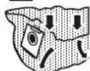
▶ Regularly clean the fill level sensors [5] and empty the dirt trap.
Observe the following information:
- Dust-related inspection (e.g. for filter damage, tightness of the machine and function of the control devices) by the manufacturer or an instructed person at least once a year.
- Dispose of components that cannot be cleaned. Use impermeable bags to do so. Observe the applicable disposal provisions.
- Provided maintenance personnel or other persons in the vicinity are not endangered, the user must dismantle and clean the machine prior to performing maintenance work. Appropriate precautionary measures include decontaminating the machine prior to disassembly, making provisions for locally filtered forced ventilation at the location of machine disassembly, cleaning the maintenance area and appropriate personal protective equipment.
10.1 Filter bag / disposal bag / main filter
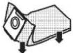
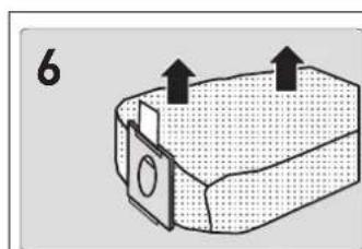
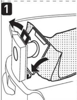
▶ Remove the filter bag [6].
▶ Insert the filter bag [7].
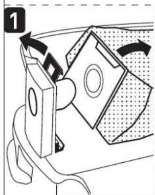
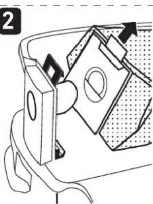
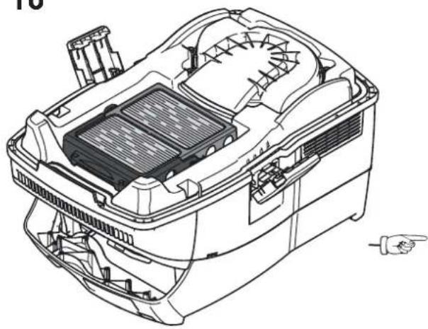
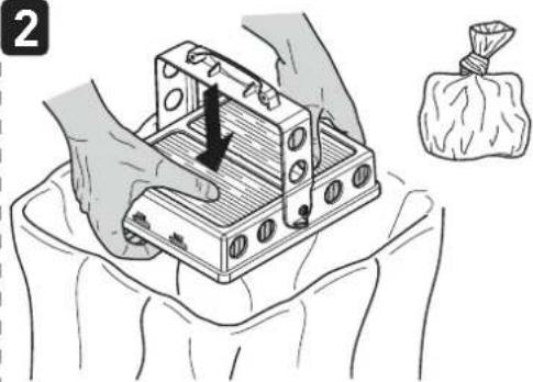
▶ Remove the disposal bag [8].
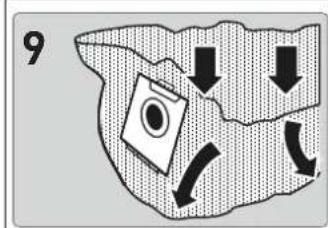
▶ Insert the disposal bag [9].
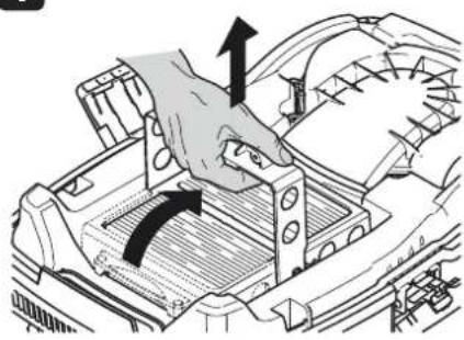
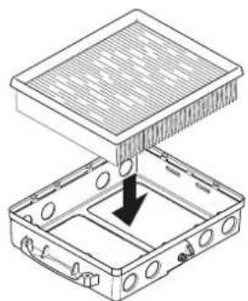
▶ Change the main filter [10].
Dispose of the used filter in accordance with statutory regulations.
The order numbers for accessories, filters and consumables can be found in the Festool catalogue or on the internet at www.festool.com.
11 Accessories
Refer to the Festool catalogue for the order numbers of accessories and filters or find them online at "www.festool.com".
11.1 Modules
The following modules for extending the mobile dust extractor are available in the range of accessories, and can be connected to the electrical outlet module [1-2] :
- SD I-CT26-48 (socket module)
- DL I-CT26-48 (compressed-air module)
For more information about the modules, visit "www.festool.com".
12 Environment

Do not dispose of the device in the household waste! Recycle devices, accessories and packaging. Observe applicable national regulations.
In accordance with the European Directive on waste electrical and electronic equipment and implementation in national law, used electrical devices must be collected separately and handed in for environmentally friendly recycling.
Information on the collection points can be viewed at www.festool.com/environment.
Information on critical materials:
www.festool.co.uk/reach
13 General information
Imported into the UK by
Festool UK Ltd
1 Anglo Saxon Way
Bury St Edmunds
IP30 9XH
Great Britain
13.1 Bluetooth®
The Bluetooth ^® word mark and the logos are registered trademarks of Bluetooth SIG, Inc.; they are used by TTS Tooltechnic Systems AG & Co. KG, and therefore by Festool, under licence.
13.2 Licence information
Licence information on any open source licences used in the product can be found in the
Festool app* at Information > Power tool open source licenses.
* Not available in all countries.
13.3 Information on data privacy
The power tool contains a chip which automatically stores machine and operating data. The data saved cannot be traced back directly to an individual.
The data can be read in a contactless manner using special devices and shall only be used by Festool for fault diagnosis, repair and warranty processing and for quality improvement or enhancement of the power tool. The data shall not be used in any other way without the express consent of the customer.
Sommaire
13.2 Informations relatives aux licences
- Tim Weber
- Inhaltsverzeichnis
- Safety warnings
- Symbols
- Parts of the machine
- Intended use
- Commissioning
- WARNING
- Unauthorised voltage or frequency!
- Risk of accidents
- Initial commissioning
- Connecting a mobile dust extractor
- Risk of injury from power tools starting up unexpectedly
- Risk of injury from electric current
- Connecting the mobile dust extractor to a mains socket
- Switching the mobile dust extractor to standby mode
- Starting the mobile dust extractor automatically
- Starting the mobile dust extractor manually
- Connecting a device
- Risk of injury from the mobile dust extractor starting up unexpectedly
- Connecting a power tool
- Risk of injury
- Connecting a mains-powered power tool to the mobile dust extractor
- Connecting a battery-powered power tool to the mobile dust extractor
- English
- Connecting the CT-F I remote control
- Connecting the remote control and the mobile dust extractor
- Switching on/off
- Resetting on the remote control
- Festool app\*
- Settings
- Adjusting the suction power
- Connecting sleeve
- Open
- Close
- Applying the brake
- Temperature cut-out
- LED lights up red Excessive temperature
- Working
- Handling
- AUTOCLEAN – cleaning the main filter (variants with AUTOCLEAN only)
- Switching automatic cleaning on and off
- Manual cleaning
- Full manual cleaning
- Within 1 minute maximum:
- Special features of the CTL 36 E AC-LHS
- Bypass function
- Extracting dry materials
- Hazardous dust
- Extracting wet materials/liquids
- Damage to the respiratory passage
- Escaping foam and liquids
- After finishing work
- Service and maintenance
- Risk of injury, electric shock
- Customer service and repairs must only be carried out by the manufacturer or service workshops. You must only use original Festool spare parts.
- Observe the following information:
- Filter bag / disposal bag / main filter
- Accessories
- Modules
- Environment
- Information on critical materials:
- General information
- Imported into the UK by
- Bluetooth®
- Licence information
- Information on data privacy
- Sommaire
- Informations relatives aux licences
Brand : FESTOOL
Model : Cleantec CTL 36 AC PLANEX
Category : Vacuum Cleaner