D25417 - Hammer DEWALT - Free user manual and instructions
Find the device manual for free D25417 DEWALT in PDF.
| Product type | Rotary hammer |
| Brand | DEWALT |
| Model | D25417 |
| Voltage | 230 V AC |
| Power consumption | 1000 W |
| Frequency | 50 Hz |
| No-load speed | 0–820 min⁻¹ |
| No-load impact rate | 0–4700 bpm |
| Single impact energy (EPTA 05/2009) | 4.2 J |
| Max. drilling capacity in steel | 13 mm |
| Max. drilling capacity in wood | 32 mm |
| Max. drilling capacity in concrete | 32 mm |
| Core drilling capacity in soft brick | 100 mm |
| Tool holder | SDS Plus |
| Chisel positions | 12 |
| Ring diameter | 60 mm |
| Weight | 4.3 kg |
| Sound pressure level (LPA) | 86 dB(A) |
| Sound power level (LWA) | 97 dB(A) |
| Vibration – drilling in concrete (ah) | 8.2 m/s² |
| Vibration – chiseling (ah) | 7.1 m/s² |
| Anti-rotation system | Yes |
| Torque limiter clutch | Yes |
| Double insulation | Yes |
| Side handle | Yes, included |
| Depth stop | Yes, included |
| Keyless chuck | Yes (for D25417) |
| Package contents | Drill, side handle, depth adjustment rod, carrying case, keyless chuck, instruction manual |
| Maintenance | Clean ventilation slots with compressed air; no additional lubrication |
| Repairability | Auto-stop motor brushes; spare parts available at authorized centers |
| Safety | Wear hearing and eye protection; use auxiliary handle; disconnect before adjustment |
Frequently Asked Questions - D25417 DEWALT
User questions about D25417 DEWALT
0 question about this device. Answer the ones you know or ask your own.
Ask a new question about this device
Download the instructions for your Hammer in PDF format for free! Find your manual D25417 - DEWALT and take your electronic device back in hand. On this page are published all the documents necessary for the use of your device. D25417 by DEWALT.
USER MANUAL D25417 DEWALT
D25413, D25417, D25430
Tillykke!
2006/42/EF,EN60745-1:2009+A11:2010,EN60745-2-6:2010.
D25413, D25417, D25430
D25413, D25417, D25430
Congratulations!
You have chosen a DEWALT tool. Years of experience, thorough product development and innovation make DEWALT one of the most reliable partners for professional power tool users.
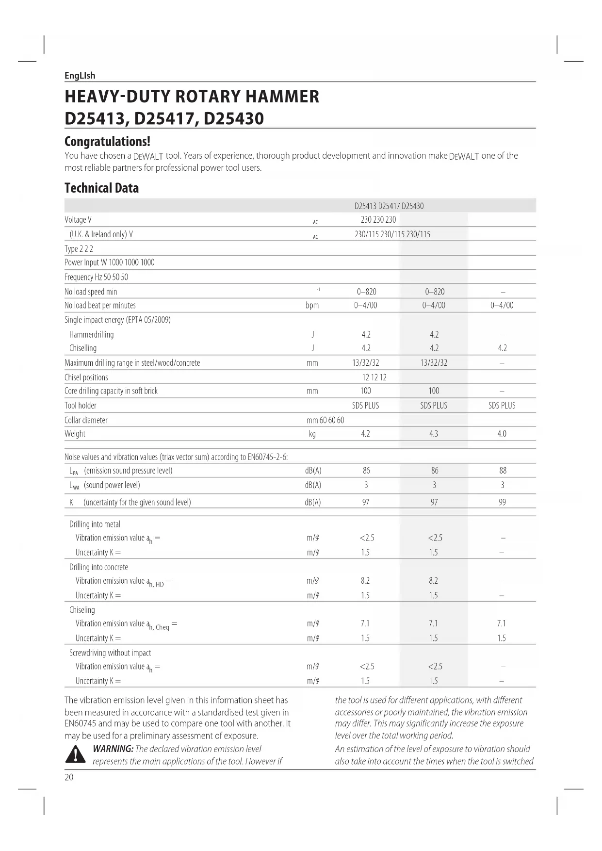
Technical Data
| D25413 D25417 D25430 | ||||
| Voltage V | AC | 230 230 230 | ||
| (U.K. & Ireland only) V | AC | 230/115 230/115 230/115 | ||
| Type 2 2 2 | ||||
| Power Input W 1000 1000 1000 | ||||
| Frequency Hz 50 50 50 | ||||
| No load speed min | -1 | 0-820 | 0-820 | - |
| No load beat per minutes | bpm | 0-4700 | 0-4700 | 0-4700 |
| Single impact energy (EPTA 05/2009) | ||||
| Hammerdrilling | J | 4.2 | 4.2 | - |
| Chiselling | J | 4.2 | 4.2 | 4.2 |
| Maximum drilling range in steel/wood/concrete | mm | 13/32/32 | 13/32/32 | - |
| Chisel positions | 12 12 12 | |||
| Core drilling capacity in soft brick | mm | 100 | 100 | - |
| Tool holder | SDS PLUS | SDS PLUS | SDS PLUS | |
| Collar diameter | mm 60 60 60 | |||
| Weight | kg | 4.2 | 4.3 | 4.0 |
| Noise values and vibration values (triax vector sum) according to EN60745-2-6: | ||||
| \( L_{PA} \)(emission sound pressure level) | dB(A) | 86 | 86 | 88 |
| \( L_{WA} \)(sound power level) | dB(A) | 3 | 3 | 3 |
| K(uncertainty for the given sound level) | dB(A) | 97 | 97 | 99 |
| Drilling into metal | ||||
| Vibration emission value \( a_h = \) | m/3 | <2.5 | <2.5 | - |
| Uncertainty K= | m/3 | 1.5 | 1.5 | - |
| Drilling into concrete | ||||
| Vibration emission value \( a_h, _{H D} = \) | m/3 | 8.2 | 8.2 | - |
| Uncertainty K= | m/3 | 1.5 | 1.5 | - |
| Chiseling | ||||
| Vibration emission value \( a_h, _{Cheq} = \) | m/3 | 7.1 | 7.1 | 7.1 |
| Uncertainty K= | m/3 | 1.5 | 1.5 | 1.5 |
| Screwdriving without impact | ||||
| Vibration emission value \( a_h = \) | m/3 | <2.5 | <2.5 | - |
| Uncertainty K= | m/3 | 1.5 | 1.5 | - |
The vibration emission level given in this information sheet has been measured in accordance with a standardised test given in EN60745 and may be used to compare one tool with another. It may be used for a preliminary assessment of exposure.

WARNING: The declared vibration emission level represents the main applications of the tool. However if
the tool is used for different applications, with different accessories or poorly maintained, the vibration emission may differ. This may significantly increase the exposure level over the total working period.
An estimation of the level of exposure to vibration should also take into account the times when the tool is switched
off or when it is running but not actually doing the job. This may significantly reduce the exposure level over the total working period.
Identify additional safety measures to protect the operator from the effects of vibration such as: maintain the tool and the accessories, keep the hands warm, organisation of work patterns.
EC-Declaration of Conformity
Machinery Directive

Heavy-Duty Rotary Hammer D25413, D25417
DFWALT declares that these products described under
Technical Data are in compliance with:
2006/42/EC, EN60745-1:2009+A11:2010, EN60745-2-6:2010.
These products also comply with Directive 2014/30/EU and
2011/65/EU. For more information, please contact DEWALT at the following address or refer to the back of the manual.
D25430
DEFWALT declares that these products described under
Technical Data are in compliance with:
2000/14/EC Electrical concrete breaker (hand held)
m < / = 15kg Annex VIII, TUV Rheinland LGA Products GmbH
(0197), D-90431 Nurnberg, Germany, Notified Body ID No.: 0197
Level of acoustic power according to 2000/14/EC
(Article 12,Annex III,No.10; m < / = 15~kg
L_WA (measured sound power level) dB 99
LwA (guaranteed sound power level) dB 105
The undersigned is responsible for compilation of the technical file and makes this declaration on behalf of DEWALT.

Markus Rompe
Director Engineering
D-65510, Idstein, Germany
12.08.16

WARNING: To reduce the risk of injury, read the
instruction manual.
Definitions: Safety Guidelines
The definitions below describe the level of severity for each signal word. Please read the manual and pay attention to these symbols.
DANGER: Indicates an imminently hazardous
on which, if not avoided, will result in death or
serious injury.
WARNING: Indicates a potentially hazardous situation when, if not avoided, could result in death or serious injury.
CAUTION: Indicates a potentially hazardous situation.
WRITER, if not avoided, may result in minor or moderate injury.
NOTICE: Indicates a practice not related to personal injury which, if not avoided, may result in property damage.
Diabetes risk of electric shock.
Notes risk of fire.
General Power Tool SafetyWarnings
WARNING: Read all safety warnings and all
Instructions. Failure to follow the warnings and
instructions may result in electric shock, fire and/or serious injury.
SAVE ALL WARNING AND INSTRUCTIONS FOR FUTURE REFERENCE
The term "power tool" in the warnings refers to your mains-operated (corded) power tool or battery-operated (cordless) power tool.
1) Work area safety
a) Keep work area clean and well lit. Cluttered or dark areas invite accidents.
b) Do not operate power tools in explosive atmospheres, such as in the presence of flammable liquids, gases or dust. Power tools create sparks which may ignite the dust or fumes.
c) Keep children and bystanders away while operating a power tool. Distractions can cause you to lose control.
2) Electrical safety
a) Power tool plugs must match the outlet. Never modify the plug in any way. Do not use any adapter plugs with earthed (grounded) power tools.
Unmodified plugs and matching outlets will reduce risk of electric shock.
b) Avoid body contact with earthed or grounded surfaces such as pipes, radiators, ranges and refrigerators. There is an increased risk of electric shock if your body is earthed or grounded.
c) Do not expose power tools to rain or wet conditions.
Water entering a power tool will increase the risk of electric shock.
d) Do not abuse the cord. Never use the cord for carrying, pulling or unplugging the power tool. Keep cord away from heat, oil, sharp edges or moving parts. Damaged or entangled cords increase the risk of electric shock.
e) When operating a power tool outdoors, use an extension cord suitable for outdoor use. Use of a cord suitable for outdoor use reduces the risk of electric shock.
EngLlsh
f) If operating a power tool in a damp location is unavoidable, use a residual current device (RCD) protected supply. Use of an RCD reduces the risk of electric shock.
3) Personal safety
a) Stay alert, watch what you are doing and use common sense when operating a power tool. Do not use a power tool while you are tired or under the influence of drugs, alcohol or medication. A moment of inattention while operating power tools may result in serious personal injury.
b) Use personal protective equipment. Always wear eye protection. Protective equipment such as dust mask, non-skid safety shoes, hard hat, or hearing protection used for appropriate conditions will reduce personal injuries.
c) Prevent unintentional starting. Ensure the switch is in the off position before connecting to power source and/or battery pack, picking up or carrying the tool. Carrying power tools with your finger on the switch or energising power tools that have the switch on invites accidents.
d) Remove any adjusting key or wrench before turning the power tool on. A wrench or a key left attached to a rotating part of the power tool may result in personal injury.
e) Do not overreach. Keep proper footing and balance at all times. This enables better control of the power tool in unexpected situations.
f) Dress properly. Do not wear loose clothing or jewellery. Keep your hair, clothing and gloves away from moving parts. Loose clothes, jewellery or long hair can be caught in moving parts.
g) If devices are provided for the connection of dust extraction and collection facilities, ensure these are connected and properly used. Use of dust collection can reduce dust-related hazards.
4) Power tool use and care
a) Do not force the power tool. Use the correct power tool for your application. The correct power tool will do the job better and safer at the rate for which it was designed.
b) Do not use the power tool if the switch does not turn it on and off. Any power tool that cannot be controlled with the switch is dangerous and must be repaired.
c) Disconnect the plug from the power source and/or the battery pack from the power tool before making any adjustments, changing accessories, or storing power tools. Such preventive safety measures reduce the risk of starting the power tool accidentally.
d) Store idle power tools out of the reach of children and do not allow persons unfamiliar with the power tool or these instructions to operate the power tool. Power tools are dangerous in the hands of untrained users
e) Maintain power tools. Check for misalignment or binding of moving parts, breakage of parts and any
other condition that may affect the power tool's operation. If damaged, have the power tool repaired before use. Many accidents are caused by poorly maintained power tools.
f) Keep cutting tools sharp and clean. Properly maintained cutting tools with sharp cutting edges are less likely to bind and are easier to control.
g) Use the power tool, accessories and tool bits etc., in accordance with these instructions taking into account the working conditions and the work to be performed. Use of the power tool for operations different from those intended could result in a hazardous situation.
5) Service
a) Have your power tool serviced by a qualified repair person using only identical replacement parts. This will ensure that the safety of the power tool is maintained.
Additional Specific Safety Rules for Rotary Hammers
- Wear ear protectors. Exposure to noise can cause hearing loss.
- Use auxiliary handles supplied with the tool. Loss of control can cause personal injury.
- Hold power tool by insulated gripping surfaces, when performing an operation where the cutting accessory or the fastener may contact hidden wiring or its own cord. Cutting accessory contacting a "live" wire may make exposed metal parts of the power tool "live" and could give the operator an electric shock.
- Use clamps or other practical way to secure and support the workpiece to a stable platform. Holding the work by hand or against your body is unstable and may lead to loss of control.
- Wear safety goggles or other eye protection. Hammering operations cause chips to fly. Flying particles can cause permanent eye damage. Wear a dust mask or respirator for applications that generate dust. Ear protection may be required for most applications.
- Keep a firm grip on the tool at all times. Do not attempt to operate this tool without holding it with both hands. It is recommended that the side handle be used at all times. Operating this tool with one hand will result in loss of control. Breaking through or encountering hard materials such as re-bar may be hazardous as well. Tighten the side handle securely before use.
- Do not operate this tool for long periods of time. Vibration caused by hammer action may be harmful to your hands and arms. Use gloves to provide extra cushion and limit exposure by taking frequent rest periods.
- Do not recondition bits yourself. Chisel reconditioning should be done by an authorized specialist. Improperly reconditioned chisels could cause injury.
- Wear gloves when operating tool or changing bits.
- Accessible metal parts on the tool and bits may get extremely
hot during operation. Small bits of broken material may damage bare hands.
- Never lay the tool down until the bit has come to a complete stop. Moving bits could cause injury.
- Do not strike jammed bits with a hammer to dislodge them. Fragments of metal or material chips could dislodge and cause injury.
- Slightly worn chisels can be resharpened by grinding.
- Keep the power cord away from the rotating bit. Do not wrap the cord around any part of your body. An electric cord wrapped around a spinning bit may cause personal injury and loss of control.
WARNING: We recommend the use of a residual current with a residual current rating of 30mA or less.
Residual Risks
The following risks are inherent to the use of rotary hammers:
- injuries caused by touching the rotating parts or hot parts of the tool.
In spite of the application of the relevant safety regulations and the implementation of safety devices, certain residual risks cannot be avoided. These are:
Impairment of hearing.
- Risk of squeezing fingers when changing the accessory.
- Health hazards caused by breathing dust developed when working in concrete and/or masonry.
Electrical Safety
The electric motor has been designed for one voltage only. Always check that the power supply corresponds to the voltage on the rating plate.

Your DEWALT tool is double insulated in accordance with EN60745; therefore no earth wire is required.
WARNING: 115 V units have to be operated via a fail-safe switching transformer with an earth screen between the primary and secondary winding.
If the supply cord is damaged, it must be replaced by a specially prepared cord available through the DEWALT service organisation.
Mains Plug Replacement (U.K. & Ireland Only)
If a new mains plug needs to be fitted:
- Safely dispose of the old plug.
- Connect the brown lead to the live terminal in the plug.
- Connect the blue lead to the neutral terminal.
WARNING: No connection is to be made to the terminal.
Follow the fitting instructions supplied with good quality plugs. Recommended fuse: 13 A.
Using an Extension Cable
An extension cord should not be used unless absolutely necessary. Use an approved extension cable suitable for the power input of your charger (see Technical Data). The
minimum conductor size is 1.5mm^2 the maximum length is 30m
When using a cable reel, always unwind the cable completely.
Package Contents
The package contains:
1 Rotary hammer (D25413, D25417 only) or
1 Chipping hammer (D25430)
1 Side handle
1 Depth adjustment rod (D25413, D25417 only)
1 Kitbox
1 Keyless chuck (D25417 only)
1 Instruction manual
- Check for damage to the tool, parts or accessories which may have occurred during transport.
- Take the time to thoroughly read and understand this manual prior to operation.
Markings on Tool
The following pictograms are shown on the tool:

Read instruction manual before use.

Wear ear protection.

Wear eye protection.
Date Code Position
The date code which also includes the year of manufacture, is printed into the housing.
Example:
2019 XX XX
Year of Manufacture
Description (Fig. A-D, F)
WARNING: Never modify the power tool or any part of it.
Age or personal injury could result.
1 Variable speed switch
2 Main handle
3 Forward/reverse slider
4 Mode selector
5 Safety lock
6 Side handle
7 Tool holder/locking sleeve
8 Shocks
9 LED Indicator (D25417 only)
10 Depth adjustment rod (D25413, D25417 only)
11 Depth stop clamp
12 Locking collar
13 Chuck (D25417 only)
ENGLISH
14 Dust cover
15 Lock on button (D25430 only)
Intended Use
D25413, D25417
These heavy-duty rotary hammers have been designed for professional drilling and hammerdrilling, screwdriving and light chipping.
D25430
This chipping hammer has been designed for professional chipping, chiselling and demolition applications.
DO NOT use under wet conditions or in the presence of flammable liquids or gases.
These hammerdrills are professional power tools.
DO NOT let children come into contact with the tool.
Supervision is required when inexperienced operators use this tool.
- Young children and the infirm. This appliance is not intended for use by young children or infirm persons without supervision.
- This product is not intended for use by persons (including children) suffering from diminished physical, sensory or mental abilities; lack of experience, knowledge or skills unless they are supervised by a person responsible for their safety. Children should never be left alone with this product.
Active Vibration Control (Fig. A)
The active vibration control neutralises rebound vibration from the hammer mechanism. Lowering hand and arm vibration allows for more comfortable use for longer periods of time and extends the life of the unit.
For best vibration control, hold the tool with one hand on the main handle 2 and the other hand on the side handle 6. Apply just enough pressure so the hammer is approximately mid-stroke.
The hammer only needs enough pressure to engage the active vibrator control. Applying too much pressure will not make the tool drill or chip faster and active vibration control will not engage.
Torque Limiting Clutch
WARNING: The user must always maintain a firm grip on the wall when in operation.
The torque limiting clutch reduces the maximum torque reaction transmitted to the operator in case of jamming of a drill bit. This feature also prevents the gearing and electric motor from stalling.
NOTICE: Always turn the tool off before changing torque control settings or damage to tool may result.
Anti Rotation System (Fig. B)
D25417
The anti rotation system offers increased user comfort and safety through an on-board, anti-rotation technology capable of detecting if the user loses control of the hammer. When a jam is detected, the torque and speed are stopped instantly. This feature prevents self rotation of the tool reducing the
occurrence of wrist injuries. The red LED indicator 9 lights up if the anti-rotational device is activated.
Under exposure of certain electromagnetic phenomena (fast transients) it can happen that the machine will reduce speed down to zero RPM. This will be shown by flashing of the LED indicator 9. To undo this mode the machine needs to be switched off and on one time. After cycling the variable speed switch 1 the machine is back in normal operating mode.
ASSEMBLY AND ADJUSTMENTS
WARNING: To reduce the risk of serious personal injury, turn tool off and disconnect tool from power source before making any adjustments or removing/ installing attachments or accessories. Be sure the trigger switch is in the OFF position. An accidental start-up can cause injury.
Selecting the Operating Mode (Fig. C)
D25413, D25417
The tool can be used in the following operating modes:

Rotary drilling: for screwdriving and for drilling into steel, wood and plastics.

Hammerdrilling: for concrete and masonry drilling operations.

Hammering only: for light chipping, chiselling and demolition applications. In this mode the tool can also be used as a lever to free a jammed drill bit
D25430
The tool can be used in the following operating modes:

Hammering only: for light chipping, chiselling and demolition applications. In this mode the tool can also be used as a lever to free a jammed drill bit.
- To select the operating mode, press the safety lock 5 and rotate the mode selector switch 4 until it points to the symbol of the required mode.
- Release the safety lock and check that the mode selector switch is locked in place.
WARNING: Do not select the operating mode when the team running.
Indexing the Chisel Position (Fig. C)
The chisel can be indexed and locked into 12 different positions.
- Rotate the mode selector switch 4 until it points to the hammerdrill mode symbol. Refer to Selecting the Operating Mode in Assembly and Adjustments.
- Rotate the chisel in the desired position.
- Set the mode selector switch 4 to the hammering only position.
- Twist the chisel until it locks in position.
Inserting and Removing SDS PLUS Accessories (Fig. D)
This tool uses SDS PLUS accessories (refer to the inset in Figure D for a cross-section of an SDS PLUS bit shank). We recommend using professional accessories only.
- Clean and grease the bit shank.
- Insert the bit shank into the tool holder/locking sleeve 7.
- Push the bit down and turn it slightly until it fits into the slots.
- Pull on the bit to check if it is properly locked. The hammering function requires the bit to be able to move axially several centimetres when locked in the tool holder.
- To remove a bit, pull back the tool holder/locking sleeve 7 and pull out the bit.
WARNING: Always wear gloves when you change accessories. The exposed metal parts on the tool and accessory may become extremely hot during operation.
Fitting the Side Handle (Fig. A)
The side handle 6 can be fitted to suit both RH- and LH-users.
WARNING: Do not use the tool without the side handle properly assembled.
- Loosen the side handle.
- For RH-users: slide the side handle clamp over the collar behind the tool holder, handle at the left. For LH-users: slide the side handle clamp over the collar behind the tool holder, handle at the right.
- Rotate the side handle to the desired position and tighten the handle.
Setting the Drilling Depth (Fig. D)
D25413, D25417 only
- Insert the required drill bit as described above.
- Press the depth stop clamp 11 and keep it depressed.
- Fit the depth adjustment rod 10 through the hole in the depth stop clamp.
- Adjust the drilling depth as shown.
- Release the depth stop clamp.
Forward/reverse Slider (Fig. E)
- Push the forward/reverse slider 3 to the LH-side for forward (RH) rotation. See arrows on tool.
- Push the forward/reverse slider 3 to the RH-side for reverse (LH) rotation.
WARNING: Always wait until the motor has come to complete standstill before changing the direction of rotation.
Fitting a Chuck Adapter and Chuck Sold Separately
Screw a chuck onto the threaded end of the chuck adapter.
-
Insert the connected chuck and adapter in the tool as though it were a standard SDS PLUS bit.
-
To remove the chuck, proceed as for removing a standard SDS PLUS bit.
WARNING: Never use standard chucks in the sandcrushing mode.
Consult your dealer for further information on the appropriate accessories.
Replacing the Tool Holder with the Chuck (Fig. F)
D25417 only
- Turn the locking collar 12 into the unlocking position and pull the tool holder/locking sleeve 7 off.
- Push the chuck 13 onto the spindle and turn the locking collar into the locking position.
- To replace the chuck with the tool holder, first remove the chuck the same way as the tool holder was removed. Then place the tool holder the same way as the chuck was placed.
WARNING: Never use standard chucks in the serdrilling mode.
Replacing the Dust Cover (Fig. A, D)
The dust cover 14 prevents dust ingress into the mechanism. Replace a worn dust cover immediately.
- Pull back the tool holder locking sleeve 7 and pull the dust cover 14 off.
- Fit the new dust cover.
- Release the tool holder locking sleeve.
OPERATION
Instructions for Use
WARNING: Always observe the safety instructions and applicable regulations.
WARNING: To reduce the risk of serious personal injury, turn tool off and disconnect tool from power source before making any adjustments or removing/ installing attachments or accessories. Be sure the trigger switch is in the OFF position. An accidental start-up can cause injury.
WARNING: be aware of the location of pipework and wiring.
- Apply only a gentle pressure to the tool (approx. 5kg ). Excessive force does not speed up drilling but decreases tool performance and may shorten tool life.
- Do not drill or drive too deep to prevent damage to the dust cover.
- Always hold the tool firmly with both hands and ensure a secure stance (Fig. G). Always operate the tool with the side handle properly mounted.
Proper Hand Position (Fig. G)
WARNING: To reduce the risk of serious personal injury, AYs use proper hand position as shown.
ENGLISH
WARNING: To reduce the risk of serious personal injury, ALWAYS hold securely in anticipation of a sudden reaction.
Proper hand position requires one hand on the side handle 6, with the other hand on the main handle 2.
Overload Clutch
If the drill bit becomes jammed or caught, the drive to the drill spindle is interrupted by the overload clutch. Because of the forces that occur as a result, always hold the machine securely with both hands and take a firm stance.
Switching On and Off (Fig. A)
- To run the tool, press the variable speed switch 1. The pressure exerted on the variable speed switch determines the tool speed.
- To stop the tool, release the switch.
- To lock the tool in the off position, move the forward/reverse slider 3 to the central position.
Hammerdrilling (Fig. A)
Drilling with a Solid Bit
- Set the mode selector switch 4 to the hammerdrilling position. Refer to Selecting the Operating Mode in Assembly and Adjustments.
- Insert the appropriate drill bit. NOTE: For best results use high quality carbide-tipped bits.
- Adjust the side handle 6 as required.
- If necessary, set the drilling depth.
- Mark the spot where the hole is to be drilled.
- Place the drill bit on the spot and switch on the tool.
- Always switch off the tool when work is finished and before unplugging.
Drilling with a Core Bit (Fig. A, C)
- Set the mode selector 4 to the hammerdrilling position. Refer to Selecting the Operating Mode in Assembly and Adjustments.
- Adjust the side handle 6 as required.
- Insert the appropriate core bit.
- Assemble the centredrill into the core bit.
- Place the centredrill on the spot and press the variable speed switch 1. Drill until the core penetrates into the concrete approx. 1 cm.
- Stop drilling and remove the centredrill. Place the core bit back into the hole and continue drilling.
- When drilling through a structure thicker than the depth of the core bit, break away the round cylinder of concrete or core inside the bit at regular intervals. To avoid unwanted breaking away of concrete around the hole, first drill a hole the diameter of the center drill completely through the structure. Then drill the cored hole halfway from each side.
- Always switch off the tool when work is finished and before unplugging.
Rotary Drilling (Fig. C)
D25413, D25417 only
- Set the mode selector switch 4 to the rotary drilling position. Refer to Selecting the Operating Mode in Assembly and Adjustments.
- Fit the chuck adapter/chuck assembly.
- Proceed as described for hammerdrilling.
WARNING: Never use standard chucks in the Hammerdrilling mode.
Screwdriving (Fig. A, C)
D25413, D25417 only
- Set the mode selector switch 4 to the rotary drilling position. Refer to Selecting the Operating Mode in Assembly and Adjustments.
- Select the direction of rotation.
- Insert the special SDS PLUS screwdriving adaptor for use with hexagonal screwdriver bits.
- Insert the appropriate screwdriver bit. When driving slotted head screws always use bits with a finder sleeve.
- Gently press the variable speed switch 1 to prevent damage to the screw head. In reverse (LH) rotation the tool speed is automatically reduced for easy screw removal.
- When the screw is flush with the workpiece, release the variable speed switch to prevent the screw head from penetrating into the workpiece.
Chipping and Chiselling (Fig. A, C)
- Set the mode selector switch 4 to the hammering only position. Refer to Selecting the Operating Mode in Assembly and Adjustments.
- Insert the appropriate chisel and rotate it by hand to lock it into one of 12 positions.
- Adjust the side handle 6 as required.
- Switch on the tool and start working.
- Always switch off the tool when work is finished and before unplugging.
WARNING: Do not use this tool to mix or pump easily combustible or explosive fluids (benzine, alcohol, etc.).
- Do not mix or stir flammable liquids labelled accordingly.
MAINTENANCE
Your DEWALT power tool has been designed to operate over a long period of time with a minimum of maintenance. Continuous satisfactory operation depends upon proper tool care and regular cleaning.
WARNING: To reduce the risk of serious personal injury, turn tool off and disconnect tool from power source before making any adjustments or removing/ installing attachments or accessories. Be sure the trigger switch is in the OFF position. An accidental start-up can cause injury.
Motor Brushes
DEWALT uses an advanced brush system which automatically stops the drill when the brushes wear out. This prevents serious damage to the motor. New brush assemblies are available at authorised DEWALT service centers. Always use identical replacement parts.

Lubrication
Your power tool requires no additional lubrication.

Cleaning
WARNING: Blow dirt and dust out of the main housing with dry air as often as dirt is seen collecting in and around the air vents. Wear approved eye protection and approved dust mask when performing this procedure.
WARNING: Never use solvents or other harsh chemicals for cleaning the non-metallic parts of the tool. These chemicals may weaken the materials used in these parts. Use a cloth dampened only with water and mild soap. Never let any liquid get inside the tool; never immerse any part of the tool into a liquid.
Optional Accessories
WARNING: Since accessories, other than those offered by DFWALT, have not been tested with this product, use of such accessories with this tool could be hazardous. To reduce the risk of injury, only DFWALT recommended accessories should be used with this product.
Consult your dealer for further information on the appropriate accessories.
Protecting the Environment
Separate collection. Products and batteries marked with this symbol must not be disposed of with normal household waste.
- Products and batteries contain materials that can be recovered or recycled reducing the demand for raw materials. Please recycle electrical products and batteries according to local provisions. Further information is available at www.2helpU.com.
MARTILLO ROTATORIO PARA TRABAJOS PESADOS
D25413, D25417, D25430
jEnhorabuena!
D25413, D25417, D25430
Felicitations!
(Isolation double) -utils
Martelage-perforage (Fig. A)
D25413, D25417, D25430
Congratulations!
AUYERTENZA: are attn
D25413, D25417, D25430
Director Engineering
DFWALT, Richard-Slinger-Strase 11,
BEWAAR ALLE WAARSCHUWINGEN EN INSTRUCTIES ALS TOEKOMSTIG REFERENTIEMATERIALAAL
D25413, D25417, D25430
Gratuler!
Glidebryter forover/revers (Fig. E)
- Skyy glidebryteren forover/revers 3 til venstre for forover (hoyrehendte) rotasjon. Se piler pa verktoyet.
- Skyv glidebryteren forover/revers 3 til hoyre for revers (venstrehendte) rotasjon.
D25413, D25417, D25430
Gratuler!
Director de Engenharia
D25413, D25417, D25430
Onnittelut!
D25413, D25417, D25430
Gratulerar!
D25413, D25417, D25430
Tebrikler!
Evdeicic enavw oTo epyaaleio
Enavw oTo epyaIeio emuaviovtai Ta npakatw EIKOVoypauata:

AiaβaTe To Exyepidio oynyiv npiv ano T xprn.

Opate npootateutika yia ta autia.

Φopáte προτateutika γia ta ματια.
Oeesh Kwδikou Hερομηνiac
O kwokoc nepounvia o onoic nepiaaabei enionc to etoc kataokeuc, eivai twnueoc enaw oto nepiBna.
Papadiyua:
2019 XX XX
EtoCkataaKeunc
IIepiypaqn (Eik. [Fig.] A-D, F)
PNEIADONOH: Mny Tponooinae note to
pkiokepyaleio n onoiobnote turma tou. Mnpeiva
pokaiBlaabn npooanikoc tpaumiaoic.
1 Diakottnpouthetaianctaxutntac
2 Kupiaaαβn
3Zupóevocpuθmuotncμnpoc/omiaov
4 Emoyac tponou aeitoupyiac
5 Kαειδωμα ασραλεια
6πεupiknλβn
7 Ynio8oxynepyaaieivw/koλapo aopalionc
A uopTioep
9 Evdekikniuxvia LED (D25417 mvo)
10 Paβδoc puθμionc βαθouc (D25413, D25417 μóvo)
11 Szpiyktnapoc otton Baoouc
12 Koλapo aφρλiΩηc
13 Took (D25417 ovo)
14 KaLua npoTaia cno kOvN
15 Koupi aopalionc oevepyoinmuyn kataotaon (D25430 0vo)
PpooepoEvn Xpnon
D25413,D25417
Ouynanc ano0anc neipotpopikc opupec oxediaatnkv yia
enayyemaatikec epapuoyec diatponnc xphonc apupoputnavou,
biwmuoc kai eaappie cepyaaoic anokomnic.
D25430
H opupa oac anoienioc exei oxediataei yia enayyepaikec epapouyc aoanlenioc, ouiueuongkai dojikov epyaoiv thpuonc.
Na MH xpoaioioieiata oe ouvOKeC uypaoiac n otav unapoxuv eupkcta uypa n aepia.
Ta opupotpuimava evai enayveIaiknAekptikaepyaleia.
MHN aqivete ta naia va epxovtae enapn m To epyaieio. Anateiata eniBleyn otav to epyaieio auto xnpoiopoietai ano un Emuipouc xepiotec.
To npoiov auto dev npoopietyai xphon ano atoa (nepiaabavouevw naibw) nov exouv meiwvec oawatikec, ai0htnpiakec n vnuatikc icavotntec, n Elambdaen epiipac kai/n ywwoc kai deiotntwv, ektoc av ta atopaaut aetiBenovtai ano atoiouneuvoyia tvv aoopaia touc Ta naia dev npenei va evouv note mova touc e auto to npoiov.
Evpyoc xepioooc dovnoc (Eik. A)
O evpyoc xieipiaooc dovnoc eoudebetepwvei th doynon avannoanc ao to uxavioa opupac. H elattwn on tnc doynanc oTO xepai kai to paxiva entpenei thn iaovet npoh yia meyalutepa xovikdaiaotnata kai ekteivei th diapkeia cng tou epyaleiou.
Tia kautepo eleyxo tnc dovnoc, kpatate to epyaieo me to eva xepi otyn kupia labn 2 kal to aaaa xepi otny nleupikn labn 6. Expapucetetoon nion wote n opupa va bpioketai kata pooeyion oto mio tcixoc tnc.
H opupa xpeiaetai eaxiotaieon yia va evpyoointheta i evpyoc xepiaoc tnc dovnoc. H epapouyn uepboiknc pieanc dev ta kavei to epyaiova aeoupyei nio ypnyopa kata tn diatponn kalto pokavioqa, evw enianc dev th a evpyoointheta o evpyoc xepiaoc tnc dovnoc.