802 D3 Prestige Edition - Speaker BOWERS & WILKINS - Free user manual and instructions
Find the device manual for free 802 D3 Prestige Edition BOWERS & WILKINS in PDF.
User questions about 802 D3 Prestige Edition BOWERS & WILKINS
0 question about this device. Answer the ones you know or ask your own.
Ask a new question about this device
Download the instructions for your Speaker in PDF format for free! Find your manual 802 D3 Prestige Edition - BOWERS & WILKINS and take your electronic device back in hand. On this page are published all the documents necessary for the use of your device. 802 D3 Prestige Edition by BOWERS & WILKINS.
USER MANUAL 802 D3 Prestige Edition BOWERS & WILKINS
Welcome and thank you for choosing
Bowers & Wilkins. Our founder, John Bowers,
believed that imaginative design, innovative engineering and advanced technology were keys that could unlock the enjoyment of audio in the home. His belief is one that we continue to share and inspires every product we design.
The 800 Series Diamond is the world's most advanced range of loudspeakers. Each model benefits from thoughtful installation, so we would suggest that you take some time to read this manual before you begin the installation process. Continue to page 5
2 Pairs of link wires
2 Midrange end caps
1 Hex key
1 Metal bar
The 800 D3, 802 D3 and 803 D3 are very heavy and we strongly suggest that they are unpacked in the room in which they are to be used by two people working together. It is also a sensible precaution to remove jewellery to negate the risk of scratching the speakers' surface finish.
The table above illustrates the component parts that are packed with the 800 D3, 802 D3 and 803 D3. In the unlikely event that anything is missing please contact the retailer from whom you purchased the speakers.
The heavier bass/mirorange grilles attach magnetically and are packed in a separate compartment to prevent movement in transit.
Tweeter diaphragms are very delicate and easily damaged. In the 800 Series Diamond we include a steel grille mesh that can protect the tweeer from many forms of damage. However, you should still exercise care when handling and cleaning your loudspeakers.
Environmental Information
This product complies with international directives, including but not limited to:
i. the Restriction of Hazardous Substances (RoHS) in electrical and electronic equipment.
ii. the Registration, Evaluation, Authorisation and restriction of Chemicals (REACH)
iii. the disposal of Waste Electrical and Electronic Equipment (WEEE).
Consult your local waste disposal authority for guidance on how properly to recycle or dispose of this product.
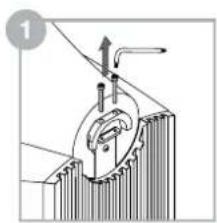
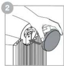
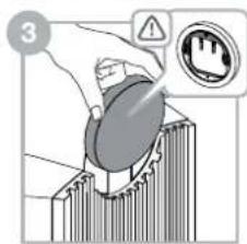
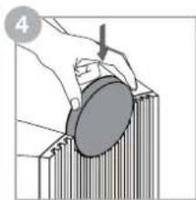
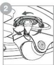
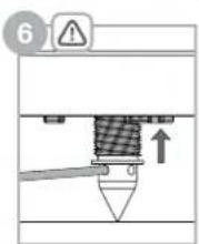
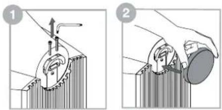
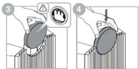
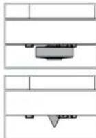
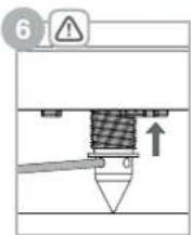
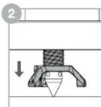
For safe transit the midrange head unit is secured by two M4 bolts to the cabinet. These bolts should be removed and the end cap fitted before use, see above illustration.
Note: Care should be taken not to damage the head finish when unscrewing the transit bolts.
Using the hex key provided unscrew both of the bolts at the rear of the head unit; keep these safe for future transit. Once the bolts have been removed offer the end cap to the rear of the head unit positioning it slightly higher than its resting position. You will notice two pegs on the inside of the end cap; ensure these are aligned to the holes where the bolts were previously removed. The end cap can now be pushed into position.
2. Positioning
Speaker Installation
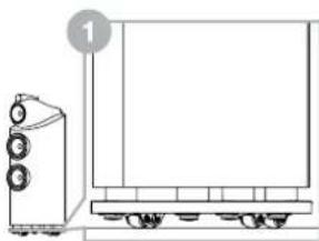
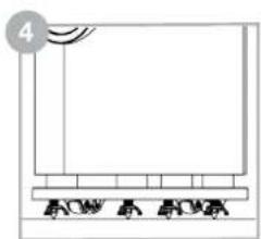
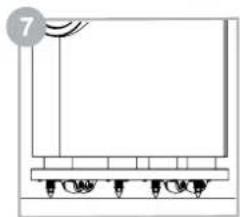
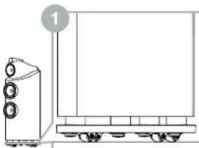
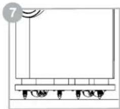
800 D3, 802 D3 and 803 D3 are intended to be floor mounted only and are supplied on wheels to aid with positioning. It is important to ensure that they stand firmly on the floor using the spike feet supplied whenever possible.
Note: If you are installing the product on very thick carpet such that the wheels prevent the speaker from resting solely on the spikes, you may wish to remove the wheels from the bottom of the plinth, using a 5mm hex (Allen) key. Due to the weight of the speakers, removal of the wheels should only be undertaken by two people - one to tilt the speaker sideways and hold it while the other removes the wheels.
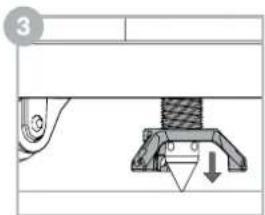
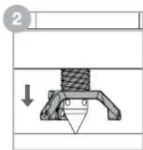
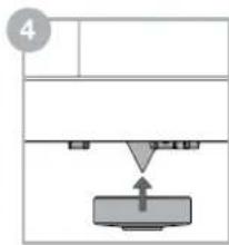
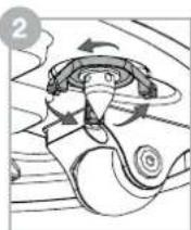
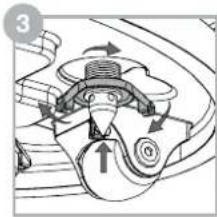
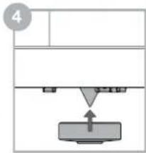
Once the speakers are in the correct position the spikes, inbuilt in the plinth, can be released. Placing your fingers in the gap between the plinth and the floor locate the four spike cups. If your speaker is positioned on a hard floor leave the spike cups in place to protect the flooring. If your speaker is on carpet remove the four spike cups, which are held magnetically, and retain them for future use. This will reveal the spike ready for it to be lowered into position.
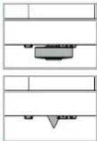
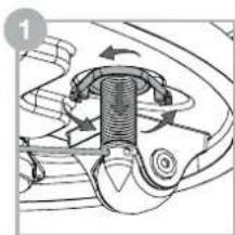
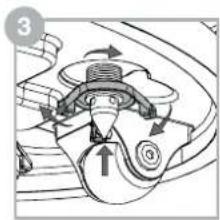
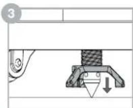
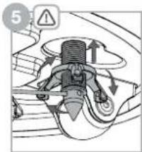
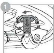
Directly above each spike/spike cup you will feel a three pronged locking nut. Using your fingers, spin the locking nut, as directed above in step 2, to lower the spike/spike cup towards the floor. If the locking nut is too tight to turn, insert the supplied metal bar into the hole at the end of one of the prongs and turn; releasing the locking nut (see above illustration).
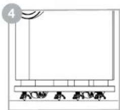
As the spike/spike cup meets the floor continue to turn the locking nut lifting the speaker off its wheels. Repeat this process with all four spikes/spike cups and adjust the height to ensure the speaker rests firmly without rocking.
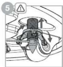
To lock the spikes/spike cups in place insert the metal bar into one of the four holes in the spikes. Using the metal bar to stop the spike turning, rotate the locking nut, as directed above in step 5. Once the locking nut is released, remove the metal bar and continue to spin the locking nut returning it to its locked position in the plinth. To ensure the locking nut is tightly locked in place reinsert the metal bar into one of the four holes on the spike. With the metal bar holding the spike in position, use your fingers to turn the locking nut until it can no longer rotate. Repeat this for each spike.
If the speaker needs to be repositioned the spikes must be returned back into the plinth before the product is moved. To do this insert the metal bar into one of the four holes on the spike. With the metal bar holding the spike in position, use your fingers to turn the locking nut, as directed above in step 2, releasing it. Then continue to spin the locking nut until it can no longer rotate; this will ensure the locking nut and spike are engaged. Now turn the locking nut, as directed above in step 3, and the spike will start ascending back into the plinth. Once the spike has been returned to the plinth replace the spike cup (if removed) and the speaker can now be repositioned.
3. Connecting
Speaker Positioning
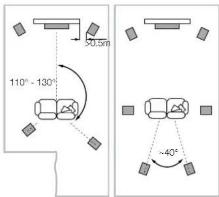
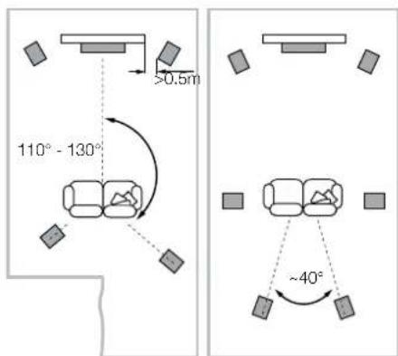
In either stereo or home theatre installations, try to ensure that the immediate surroundings of each speaker are similar in acoustic character. For example, if one speaker is adjacent to bare walls while the other is adjacent to soft furnishings and curtains, both the overall sound quality and the stereo image are likely to be compromised.
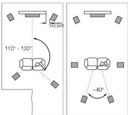
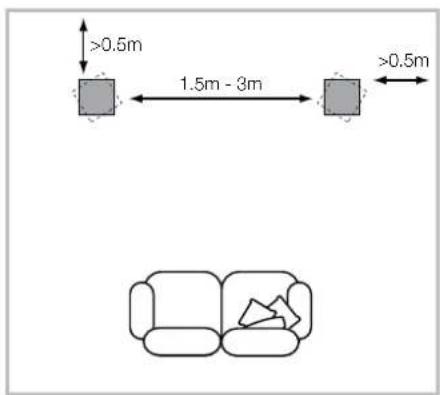
Conventional Stereo Systems
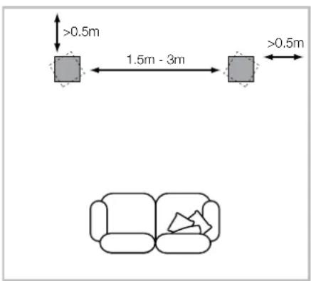
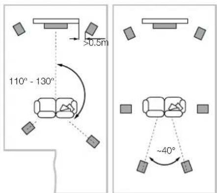
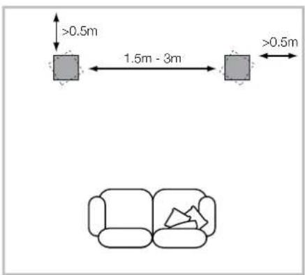
To begin with, the speakers should be positioned between 1.5m and 3m apart at two corners of an equilateral triangle completed by the listening area at the third corner. The speakers should be approximately 0.5m away from the back wall, and at least 0.5m away from any side walls (above).
5 Channels 7 Channels
Home Theatre Systems
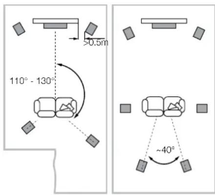
If the speakers are to be used for the front channels in a home theatre system, they should be placed closer together than for 2-channel audio, because the surround channels tend to widen the image. Positioning the speakers within approximately 0.5m of the sides of the screen will also help keep the sound image in scale with the visual image. As with conventional stereo positioning, the speakers should ideally be at least 0.5m away from any side walls.
All connections should be made with the audio equipment switched off.
The 800 D3, 802 D3 and 803 D3 speaker terminals accept a variety of cable terminations: 4mm banana plugs, 6mm and 8mm (1/4 in and 5/16 in) spades, or bare wires up to 4mm (5/32 in) diameter.

Important Safety Notice
In certain countries, notably those in Europe, the use of 4mm banana plugs is considered a safety hazard, because they may be into the holes of unshuttered mains supply. In order to comply with European CENELEC regulations, the 4mm holes in the ends of the are blocked by plastic pins. If you are using acts in any country where these conditions you should ensure that any banana plugs cannot in an unsafe manner by children or other ed persons.
Ask your dealer for advice when selecting speaker cable. Keep its total impedance below the maximum recommended in the speaker specification and use a low inductance cable to avoid attenuation of high frequencies.
- Fine Tuning
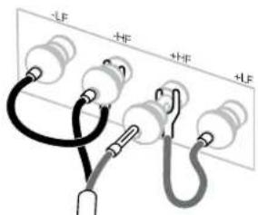
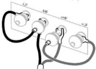
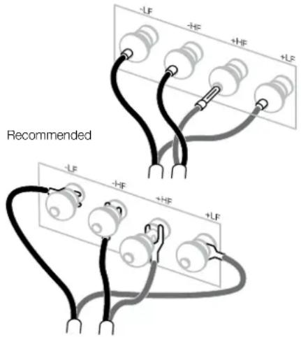
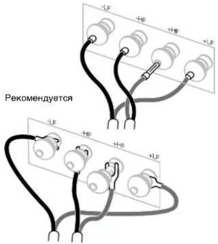
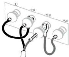
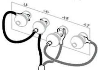
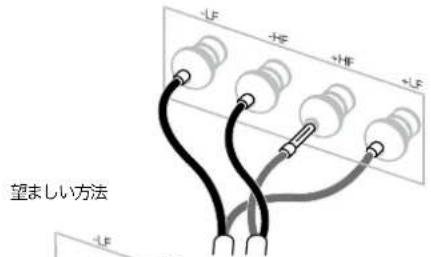
There are two pairs of terminals at the back of each speaker that enable bi-wiring (top left). For single wire connection, fit the supplied link wires to join the like polarity terminals together. Bi-wiring can improve the resolution of low-level detail.
Ensure that the positive terminals on the speaker (with red ring) are connected to the positive output terminal on the amplifier and the negative terminals on the speaker (with black ring) are always connected to the negative output terminal on the amplifier. Incorrect connection will not result in damage but will cause poor stereo imaging and loss of bass. Always screw the terminal caps down fully to prevent rattles.
Before fine tuning, make sure that all the connections in the installation are correct and secure.
Moving the speakers further from the walls will generally reduce the volume of bass. Space behind the speakers will also help to create an aural impression of depth. Conversely, moving the speakers closer to the walls will increase the volume of bass.
If the bass seems uneven with frequency this will most probably be due to resonance modes in the listening room. Even small changes in the position of the speakers or the listening position can have a profound effect on how these resonances affect the sound. Try moving the listening position or locating the speakers along a different wall. The presence and position of large pieces of furniture can also influence resonance modes.
If the central image lacks focus, try moving the speakers closer together or angling them inward so that they point at a location just in front of the listening position.
If the sound is too bright, increasing the amount of soft furnishing in the room (heavier curtains for example) may help balance the sound. Conversely, reducing the amount of soft furnishing may help brighten a dull sound.
For the most discerning listening, remove the bass/ midrange grilles by gripping around their edges and gently pulling them away from the cabinet.
-
Running In
-
Aftercare
The performance of the speaker will change subtly during the initial listening period. If the speaker has been stored in a cold environment, the damping compounds and suspension materials of the drive units will take some time to recover their correct mechanical properties. The drive unit suspensions will also loosen up during the first hours of use. The time taken for the speaker to achieve its intended performance will vary depending on previous storage conditions and how it is used. As a guide, allow up to a week for the temperature effects to stabilise and 15 hours of average use for the mechanical parts to attain their intended design characteristics.
The cabinet surfaces will usually only require dusting. We recommend you use the cloth supplied with the product. If you wish to use an aerosol or other cleaner, apply the cleaner onto the cloth, not directly onto the product and test a small area first, as some cleaning products may damage some of the surfaces. Avoid products that are abrasive, or contain acid, alkali or anti-bacterial agents. Do not use cleaning agents on the drive units. Avoid touching the drive units as damage may result.
Whenever Bowers & Wilkins speakers are finished in real wood, the finest veneers are selected and treated with an ultra-violet resistant lacquer to minimise changes in colour over time. Nevertheless, like all natural materials, the veneer will respond to its environment and a degree of colour change is to be expected. Colour differences may be rectified by exposing all the veneer surfaces equally and evenly to sunlight until the colour is uniform. This process can take several days or even weeks, but may be accelerated by careful use of an ultra-violet lamp. Wood veneered surfaces should also be kept away from direct sources of heat such as radiators and warm air vents in order to minimise the possibility of the wood veneer cracking.
- Déballage
| 2 | |
| 2 | |
| 1 | |
| 1 |
5 Channels 7 Channels
5 Channels 7 Channels
Helmkinosysteme

5 Channels 7 Channels

5 Channels 7 Channels
Sistemi Home Theatre

5 Channels 7 Channels
Home Theater Systemen
Piv an to mikpoovtroviou,beiaowte otlo ae ouvdeic nC ykataoantc evai owotc kai aoafaeic.
H anapakpvon twy nxeiw npieooTepo ano touc
toixouc yevikoc 8a meiowteynv evtaan twu maow.
O xopoc niaw oan ta nxiae th aonthei enionc
va dnoupynoe tia akouatik aoihonbaouc.
Avittheta, n metakivnon twy nxeiw naonoepepa
otouc toixouc th auenoe tnv evtaom uanaow.
Av ta naa akouyovta avoioopopa Tn auvotnta, auto kata naa mavotnta Ba oepiIeTai otc akouotikec idiotne tou watiouk aoaoanc. Akjia ka iipce aalayec otny tonoetan rav nxieiw n ttn bean akpoaanm npoov va exouv onaytki eniispaan tov tono no empezetai o hxc an tic idoiuoyvtnc. Dokipate v metakivnoote t th eon akpoanic n totoBnetote Ta xieia aac kovta ae diapopetikto lixo, av eliva duvato. H napouia kal n theon yevalaw eninawu npoei emionc va empeaoei tic akouotikec idiotnc.
Eav unapxie anwiaea eotiaoc nky kevtpiik Eikova, 8okmuote va meakivnoge ta nxieia no kovta melaou h v a touc waeet kion npoc ta eaa oate va eival opaepvna poc ma thon akipwc unpoota ano tn theon akpaoanc.
Eav o nxc evai unepoikä evtovoc, tonoetnte nepooctepa uaoata eninawonc oto domegaatio (n.x. nio bapie kouptive) via va oopponote tov xo. AvtiBETA, eav tonoetntae lyotepa uaoata eninawonc, evexetai noxoc vayivei no etovoc.
Tia nio ekkennuieyn akpoaan, aphiapeote tic ypiuee maoow/maoaic eueEaeiaac naovtac tic ano ta akpa Touc kai tpaewvtaic tia ana maekpi ano to nepiIbnja.
6.Φovtriδa kαuovtnpno
H andoon tou nxieou 0a aalace1 elaapka kata tn
diapkeia tnc apxiknc nepidook apoacn. Av to
nxieo exi anothekeutc e quxpno nepiabllov, o
ouoe anoaeoc twv kpadaopw ka ta uika
avaptnoncw vovauwobynong Cha xpeiaotouy
liyo xpovo ia va avaktnoov tio wotec muxavikec
touisiotne.Te EAqptuaatavaaptnonc ntc
movalac onbnyonco th axalapwoov enionc kata tn
diapkeia tow npaww xpwhc. Oxpoovoc nou
xpeiaetai to nxie yia va enitoxei tv andoom yia
tv noxa npoopicctai th naikalev avolova me tic
auvthekoc onou ixte anothekeutc nponyouvewc kai
tov troponxphocuTou. c kavova, va apnvte va
npaeeleewia ebaedoaia via otaepeontohov
oi empaaeic tnc thepokpaaicac kai 15 opcx nponc
kata ma oeo npokeevou ta npxavika mepn va
anoktnoov ta xapaktnpiatika oxdiaocn nou
npenei.
OeipafveieTou ppiBnmuocuvnox
Xpeiaovtaipoxoekoviaua.Suviotouva
XpnaoianoeTato nau ouvoideu npioiv.
Av bete va xnpoaionoe kantoio onepi n
aaaKabapiotko, anwote to kaBPaotiko enawv
0to navi, oxi aeueisic naev wto npioiv kai
Dokikte npata oe ma kpon npexohk, kaboceva kaBPaiotka npoiovta evexetai va
PokaiaouvNmae opiaquec antic eripaeieC
Anoepyute ta aneogtika npoiovta na Tpoivota
nou pniexov Oeigotukoc, aakaukoc n
avIbaktipiaikouc npayovtec.Mx npoionite
KaBPaTIKA otic movaec odhyonnc. Anoepuyete va
ayicete tic movaec odhyonnc, kaowc evexetai va
pnoknneziua.
Onote ta nxcia Bowers & Wilkins exovv fivipia ma an npayatiko ELO, eniEoyvat ka kalutepa EuofuAka kai unbaalovt ae eneEpyaia me evaBPVKU ov iauavekto OTNV utepwO naktioBla yva elambdaotoinBoov o alayec oTo xpuA ME TAPoSO TU XPOVou. Evoutouc, onwc Oa ta uka uAko, To EUofoopau avtippa 0to nepiBaAovTu KAI eivai avapeevoeoc evac baHOC anoxpwataou. OI diaPocxPawatoC mnpovu v AnokataaTaoBVkTeovTac EIOOU KA OMA t OTO nlaikoc fOc oLc Tc EIAPAEIEEC EuAoHauo, mepxO To xpuA va ivai OoIdojo. Aun T diaKdAIOI npoei va biApkeoi apKeTc npec n akoa kai Eboouc, aAALLvEvbExetai v emitaxuvthetai pe PooeaknXonmEvocAauntnpaa Utepiowouc WTc. OI eupaeivec eEuOFOUa thnei enionc va diatnpovui maKpi ao aaece tsyec ThepOHTAC, oWuC kALOpFepK eEAeipntpec ThepOeuap, pOKeiEvov v EaXlOtonPei nmbavota npokanq npwivw ot EuofoAlo.
- PacnaKOBka
| 2 | |
| 2 | |
| 1 | |
| 1 |
Copejahanyynakobkn
2 NapbI coeHHTenBhIX npoBOIOB
2 TopeBbIe KpbIuKn IaIcC-ronOBok
1WectnprahHbI KIOH
1 MetaJIInueckn cTePKeHb
Akyctnueckne CNTembl 800 D3,802 D3 n 803 D3 OeHb TAAKEnIbe, INoTOMy Mbl HAcTOReTbHO KEpOMeHNyEM, YTObbl Nx pacNaKOBbAnu BDoEM, PnHcBmToKOMHate, rDe OH6yDyT cToaRb.CnEyET TAKKe CHrTBcpyk BCE KOnbua y UyPkaUHe NoOpapanatbNoNIpObaHHO OTdENKyoKOHOK.
B Ta6nIe npoIIOIcTropOBaHbI DetanI, KOtOpBe lyynakOBAHbI BMeCTe C 800 D3.802 D3 n 803 D3
B MaNoBaOpTaHOM CnuAe, KOrDa Yero-NiMo He XbAaTeT, O6paAaTecB cpa3y Ke K npOdaBcY, y KOTOPORO Bbl KyTNIN NkONOHKn.
Bce 3aunTHbIe peWETKn KpENrTaH Ma HnHTax. Bonee TReKbnE 3aunTHbIe peWETKn dHa H- CuDnAMHKOB yNakOBaH B OTdNbHbIe RHeKN, YTObbl N36ExaTbX INpeMeEueHgnn PnP TaHcnpOtnpOBe.
KynolbHne dnaaparmbTBnTepeoB oeyh xpyknne n nn Kno nopeDntB.Cepnn 800 Diamond nCNOB3yOToCTaBHepepeTKn,3auuuaQoune TBnTEpOT noPBeXeHn. Ondako, npu NcTKe KOLOHOK INyUOe 3a HmH NyHXo PPOBBAITb OCTOPOXHOCTb.
Hhopmaun no 3aunne okpykaoue cpebl 3TOT npoDyKT NnHOCTbIO COOTBETCTBYET MEKdyHapOdBHM DnpekTHBaM, BKNIOUHa, HO He ORpAHNHBcB:
i. No orpaHnueHnM nCnONb3OBaHHaOn aonChbIX MaTePnAnOB (Restriction of Hazardous Substances -RoHS) B 3NeKtpuYeckOM N 3NeKtpOHmO6OpyDoBHanni
ii. No pereNCTpaun, oueHke, aTOpn3aun IN orpahnueHHIO nCNOB3OBAHH XHMnueCKHX BeueCTB - Registration, Evaluation, Authorisation and restriction of CHemicals (REACH)
iii. No yttnaun OTxOoB - Waste Electrical and Electronic Equipment - (WEEE).
IpokohcynbTpyntecbBaueMeCTHOJ
opraH3aune,KOTOPAR3aHHMaTeCyrTHnH3aunei
OTXoOB,NO BORPOcAM npabINbHO CdaNNBaEro
OobopyDabHaB yTnbl.
ДЯБЗОнACHOr TpaHcNOpTnOBKn C4-RONoBKa KpenITcR K KopnyC y NOMOuBbO DByx BOnTOB M4.3Tu6BoTb Heo6XoDmO OToBepHyb NHaTeB ToPouEByK KpbluKy NepeN cNOnb3ObaHAnMC AC, CM.NHIOCTpaMIO BbIe.
PnmuueaHne: Bybte octopoxhbl n He nopeBte OTeKy rOToBKn npN OTBNuBaHN TpAChnpTbX 60NTo8.
C NOMOsbIO npnIaraeMoro 8eCTNRpaHNOr KIOHOa TOBEPHIne O6a BonTa C3aDn rONOBK; COXPAHIne B0NTbI dNra 6dyuux npeBc0k. YdaINB BOnTbI, PNICNOHTOPueBvIO KpBIuKy K TblbHO CTPOHE C4rONOBK HEMHORo Bblte ee KOHeuHORO NOOXEHNA.Ha BHytpEnHcSTPOHE KpBIuKc Ectb Da WtntPa, KOTOpBe HxHKO CoMBeCNTb C OTBepCTHAM, rDe bbln BonTb. Tenepb KpBIuKa DOnKHBA BEPTNKAJbHo CDBHByCBn BCTaTb B HxHHe NOIXeHne.
2. Pa3meueHne
YcTaHOBka akyCTHueCKNX CnCTEm
800D3,802D3n803D3npedha3aHcHbI nHaonbHoyyCTaHOBKnOCHaEHebKOLeCNKAMnI DnOBnerEHnIXnepeBnKeHN.BaxHo y6eHTbcA, 7TO OH6yDT npOuHO cTOrbHa NOny-dnN 3TOrO nCnON3yTe pinnaraemble WnBbBCOy,rDe3TO BO3MOXHO.
PnmeHHe: EcnBbYcTahabnBaTe yCTPOCTBO HA KOBpe C rYctbM BOPCOM, PONIK MeWaiOT DNAMHK OHNpaTbC TOnbKO HA WbIP, BAM MOKeT NpTe6oBtCB CHrTB PONIK C HxKHe qactN YcTOeCTbC NMOUbO 5-MNNIMETPOBOrO WeCTmRpaHrO RKnIOA. B CBA3N C 60JIbWM BECOM DnAMHKOB CHrTHe PONIKOB DOJNXO OcyueCTBnTbC DByMa IIOdbMM: ODNH HAKNOHRe TnAMHK B CTOpOH N depjT erO, NOKA dpyroI ChnMaE pONIK.
KaK TOnbKO akCyTneCKNE CnCTeMbI 3aHaHIN npabInbHOe MeTO, uINbI, BCTPOeHHbIe B OCHOBaHNe KOLOHOK MOXHO NOYcTTb HA NON. PocSyHe naIbUbI b3a09 MEXdy NONOM OCHOBaHNEM KOLOHKn HauynaiNe TeBtepe YauKNuNIOB. EcnN BaWN akCyTneCKNE CnCTeMbI yCTaHOBHeHbI H a TepDM NOy, OCTaBeTe YauKNuNIOB Ha MeCe, YTO6bI He NobPexdAaNt. EcnN BaWN akCyTneCKNE CnCTeMbI yCTaHOBHeHbI Ha KOBpe, ydaJInte 3aunTHbIe YauKN, KOTOpBE KpenrTaC H a MarHInax, I COxPAHNTe IX dR ByduJeero nCnONbOBAHN. PoD HmN BbO6hApKHTe 5nbl, rTOBtBe K BbydBIXeHNO BHN3.
Ha pe3b6 kaqdo hna haunai Te Tn
CTONOpHbix raikn C bblctynamn Ha 06dke. Bpyhyo
OTBepHnTe CTONOpHyraKy, Ka nokka3aHo
ha pncsKHe NHexe Ha wae 2, YTO6bIOnycttB
wn/aukky do nona. Ecnn CTonOpHbie raikn
BpaiaaOTc HnXkOM Tyro, BCTABte npnanaemm
Metanlneckn CTepKeHb OBtpcTne Ha KOHe
OHOHO BbCTYNO NOBepHnTe; OCB60xJa
CTONOpHyraKy/wn (cm. INIOIOCTpauuO Bwue).
TOKNE TORO KAK WnH/chaWka KOCHETCA NONA npoDOnJXNE BpaAeHne NOODHTN KONEC C NONA. NOBTOPTE 3Ty PNOeDpy DnBCEx Yetbipex WnHOaWEK NOTPERYNIPyTe HbBCOTy TAK, YTO6bKOJONKa He KaJanaCb.
Tc0b3aФнCnpoBaTb mHn/uaWky Ha HUxHOI BbICOTe, BCTaBtpe npnIraeMbI MetaJIHnCeckM CTepKHeB bOIO n3 Ytebtpex OTBepCTm B WmNax. CTOpONIM WInn, NOBepHneCTOnOpHyo raKy, KAK NOKa3aHO BbIwe Ha WARE 5. KaK TOnbKO CTOpONHPaR aRIka OCBO6OXDeHa, BByHbTe CTepKHeN NpOdoJXnTE bpaueHne, TAK TcOblb EbpHYb rAIky B ee PfKcnpyOooee NoIOKeHBe OCHOBaHN. Tc0bTyTO 3ATaNyBt 3Ty RAky, CXTABbTe ONrTa METaJIINHeCKM CTepKHeB B ODO n3 Ytebtpex OTBepCTm B WInne. YdePknBaI CTepKHEM mHn OT npOBopAunBaHH, 3aBepHne pyKo rAIky, NOKa OH He nepeptdAHT Bpaatcb. NobTopIne 3Ty onepauINO dAn KAKDOrO n3 WInNOB.
Ecn Akyctuueckyo CNTemy Heo6xOIMO nepeBnHyb, WnblcneDyET y6paTb 6paTbNO OCHOBAHNE KOLOHN, PnJeDE YEM TPOHYB ee C MecTA. IIN 3TOBO BCTABBe MeTALINHECKN CTepKHeB b ODO h N eTbIpeX OTBepB IN WInne. YApKNBaB CTepKHeM WnIOT NPOBOPaHBAHn, BpyHyIO TBepHITe CTOnOpHyraKy, KAK NOKA3aHO HA WARE 2 NOCBOOHTe ee. 3aTEM BpaauTe raHy, NOA OH e HynPetC; TAKIM o6p3OM, Bbl cOB6OboTe raHy u NiH. Tenepb BpaauTe CTOnOpHyraKy, KAK NOKA3aHO Bblwe Ha ware 3, n WnH NaHHT eYbnpatbCB B OCHOBAHNE. Iocne TOROKa WnH 6yDet y6paH B OCHOBAHNe, BEPHTe HA MeCTO MaHINTHyO YaWKy (ecn OHa 6bIna CHATA), N TepEB KOLOHN MOXHO Bydet DBNRtBa HHOBOE METo.
3.ПодсоeДинeнe
Bb6op meTa nn KOJHOK
B cntemax domaHero Teatpa mN CTpeo CNTeMax CTapaTecb CdenaTb TAK, YTO6bl 6nJXHeE OKPxyHeNe KAKdoN KOLOHOK bIIO NOxOXM no akyCTneckm CBOYCTBAM. Hanpmeep, eann OHa DC PnMbkaet K rONbIM CTeHAM, a pyra -K MArKo MeBEN N UToPAM, TO 30 MoKET OTPaTeNbHO NOBnRt Ha 3ByaHne.
06bivhblctepeo cncTeMbbl
Дян haayana paacnojoxnte AC ha pacctoHmN ot 1,5do 3 m dpyr ot dpyra B dByx yrnx paBHOCTOPOHero TpeyrolbHMka, TeTyr nOYKOTOPORO -3TO CEHTP 30hI npocnyuBaHH. KOONKn DoXKnbl 6bTb Ha paccctoHmN no kpaHne Mepe 0,5 M OT 3aHne N 6OKOBbIX CTEN (CM.PMC.BbIe).
5 Channels 7 Channels
CnCTembl DomawHero TeaTpa
Ecnn AC nCnOlb3yIOCTaKa KpOHTaIbHbIe KaHaNbB B DOMAUMEH TEATPE, OHN DOXNHB CTOTB 6NkHe DPyr KDPyr, Yem B-2KanhaHOB HApMaHTE, T.K. TBINOBb EKAHANB paacuipraiof 06pa3. PasmeueHne AC Ha paccTcHIM npBnHtEnbHO no 0.5 M OT cTOPOH 3KpHa TaKKe NOMoTaE corNaobat MacuaTb 3ByKOBOrn 3PmTeNbHO 6p3a. KaN b Cnyae O6bHrO rCEpeo, AC dONKbI B Neane PaacnonarabcHa paCCTOHn He Mehee 0.5 M OT 3aJHn 6OKOBbIX cTH.
Bce noKIOHcHn dIaIOCTToIbKO npB bIKIOHcHOM ayDNO o6OpyOBOAHN.
KlEmMb800D3,802D3n803D3npHmHaOT 甲POKoe pa3HOo6p3Ae Ka6bIbXpa3BMeOB: 4-MM pa3bMbe“6aHahB”,nonATKN WpHIOH6MM n 8MM(1/4inn5/16 in),nnne 3aHTNHe B KOHbI Ka6BeJnDnAmETpOM Do 4 MM (5/32 in).

Baxhoe 3aMeuHHe no 6e3oNaChocTu
B HEKOTOpbix cTpaHax, B ACTHOCTN B Ebpone, INcNOb3ObaHne 4-MM pAbBeMOB
6aHHOBCHTAEcTNOTEHuaNbHOOnaChbIM,T.K.
IN NO OoM6e MOXHO BCTaBnTB ANEKTPuYeCKyO
po3eTK.DIaCOrNaOBAHn C eBPOeNCKMM
HOpMaNN6eONaCHOCTn (Evepean CENELEC),
4-MMOTBePcTHNA KOHua KNeMM 3aBNOknpoBaHb
nlaactMaccoBBm np6KaMn.ECbN bNocNo3yeTe
pOyoBKT CTOPAHe, FTe 3TN HOpMbI DeCTBYOT,
BblDOnKHb6b1bYbePeHb,HTo pa3bEmbl
6aHaHb)HE CMORYt 6b1b NpIMMeHbI DeTbMn INN
HEOCBEOMHeHBiM IIOdbMbIC OnaCHOCTbIO Dn
3dOp0Bb.
Iopocnte BaIero dInepa nopekomeHdoBaTb Ka6JIb. CtapaiTeB, TTo6BJ erO NMNEdaHC 6bln HIXe MAcMnAIBHO DOnyCTmORO B CNeUΦNkaUNa, A INHKTINBOCT ToKe 6bla Hn3KoJ, TTO6BJ He OcnA6NtB BbcOKHe TaCToBI.
- Tohka NaCTpoiKa
Ha3aHnnaHn KONOHK IMeKOTc NO DBe napbl KEMM, YTObI oBceNHTB 03MOXHOCTb NOkKnOHeHn Bn-BaePHrOM (DByXKa6beHoe, bi-wiring, CM. BBepyx CneBA). IOn b6bHOrO, ODHOKa6enbHoro NOkKnOHeHn, NOcOeHNHTe npOBoHNK K KNEHMm COOTBEcTcByOuEe NOIpaHOctn. Bn-BaePHr MOKeT yUyHtB paPaeHne HTean Hn3KO rYOpBN.
Y6eHNTcB, YTO NIOOCBAI KJIEMMA Ha KOLOHKe (C KPACHBIM KONbUOM) COEINHEHa C NIOOCBOI BbXoHOH KJIEMMO HA yCNINTe, a MNHYCOBAI HA KOJONKHe (C YEPHBM KONbUOM) COEINHEHa C MNHYCOBO BbXoHOH KJIEMMO HA yCNINTe. HeBePHOe COEINHEHe HE npBaeT K NOBpeKdENHM, HO yxyDnIT CTpeeo 0bpa3 nOcnabnt 6cabt. Bcerda 3aBmHNBaIte RoNOBKn KJIEMM Do yNOPA, YTObI h36ExaTb Bbpaui.
IpeEOKHOATeBHTOHHOHACPOKOy y6eNTecb,TOBCE NOKIOHO npabINbHO HnAEXHO.
OToBnra KOnOHKn OTCTe, BbI, Ka npabnIO, yMeHbMaTe yPoBeHb 6acOB. DcTaTOHoe pacctOAnHe N03aDn KOnOHOK No3BOaNt TaKKe co3DaTb OuYueHne rnybHb. CoOTBeTcBHeHNO, npdBnHyB KOnOHKn CTeHaM, Bbl yBeNHTe DOHO 6acOB.
HepaBHomepHoe pacnpeJeHne 6acOB 0bHNO Bb3bBaTeC TcOyHMN BONHAMN B KOMHaTe, N NO3OTOM IMeET CmBcIIN NOKcNEpIMENTHPoBAtc pacCTaHOBKO 0bOHX KOLOHOK N Bb6Opom MeCTa CNYuATEN. NpOItaTecb paONoXHTb KOLOHKN BdOJIpyrO CTeHb. Ha 3bYauHHe MOKeT NOBInrTa Daxe nepemeueHne KpyTHoM MeBen.
Ecnn 3BykoBoi 06pa3 B ueHTpe cna6oBaT, nonpo6yTe nooDBeHytb KOLOHKn 6nHexe dpY K dpyry nIe HapabNTb T TOky nepe CnyaTaENM.
Ecnn 3Byk CnHsKOM pe3Km,do6abBe MeHKoM
Me6eBn B KOHMaTe (HaNPmep, NOBcBe TaeKeBle
HTOpbl), Hn Haobopot -y6peIte nx, ecnn 3Byk
TpyXOn in 6E3xHHeHH.
IaH60eB3bckatEnbHbix CnywateNCHMMTEAaTHTBpeWETKcBCAOBOINcpeDHeAACTOHTCEKUH,B3B INx3aKpAINOCTOPOXHONotAHyB Kce6E.
5 Channels 7 Channels
家庭影院系统

5 Channels 7 Channels
家庭影院系统

5 Channels 7 Channels
S如VJWJHJU 10000000000000000000000000000000000000000000000000000000000000000000000000000000000000000000000000000
- 用
三列列列列列
S3TRELO 105
日
月 1.5m-3.0m 电 电电电电电电电电电电电电电电电电电电电电电电电电电电电电电电电电电电电电电电电电电电电电电电电电电电电电电电电电电电电电电电电电电电电电电电电电电电电电电电电电电电电电电电电电电电电电电电电电电电电电

5 Channels 7 Channels
#
EU DECLARATION OF CONFORMITY
We,
B&W Group Ltd.
whose registered office is situated at
Dale Road, Worthing, West Sussex, BN11 2BH, United Kingdom
declare under our sole responsibility that the products:
800 D3, 802 D3 and 803 D3
comply with the EU Electro-Magnetic Compatibility (EMC) Directive 89/336/EEC, in pursuance of which the following standards have been applied:
EN61000-6-1:2007
EN61000-6-3:2007
EN 55020:2007
EN 55013:2001
and comply with the EU General Product Safety 2001/95/EC, in pursuance of which the following standard has been applied:
BS EN 60065:2002 + A12:2011
This declaration attests that the manufacturing process quality control and product documentation accord with the need to assure continued compliance.
The attention of the user is drawn to any special measures regarding the use of this equipment that may be detailed in the owner's manual.

G Edwards
Executive Vice President, Operations
B&W Group Ltd.
Bowers & Wilkins
B&W Group Ltd
Dale Road
Worthing West Sussex
BN11 2BH England
T+44(0)1903221800
F+44(0)1903221801
info@bwgroup.com
www.bowers-wilkins.com
B&W Group (UK Sales)
T+44(0)1903221500
Euksales@bwgroup.com
B&W Group North America
T+19786642870
E marketing@bwgroupusa.com
B&W Group Asia Ltd
T+85234729300
Einfo@bwgroup.hk
Copyright © B&W Group Ltd. E&OE
Printed in England